Corrosion Behavior of Selectively Laser Melted CoCrFeMnNi High Entropy Alloy
by
 ,
,
Jie Ren
1,†, 
Chaitanya Mahajan
2,†,
Liang Liu
1,
David Follette
3,
Wen Chen
1,* and
Sundeep Mukherjee
2,* 1
Department of Mechanical and Industrial Engineering, University of Massachusetts, Amherst, MA 01003, USA
2
Department of Materials Science and Engineering, University of North Texas, Denton, TX 76203, USA
3
Advanced Digital Design and Fabrication Lab (ADDFab), University of Massachusetts, Amherst, MA 01003, USA
*
Authors to whom correspondence should be addressed.
†
These authors contribute equally to this work.
Metals 2019, 9(10), 1029; https://doi.org/10.3390/met9101029
Submission received: 21 August 2019
/
Revised: 16 September 2019
/
Accepted: 19 September 2019
/
Published: 23 September 2019
(This article belongs to the Special Issue Complex Concentrated Alloys (CCAs) - Current Understanding and Future Opportunities)
Abstract
:CoCrFeMnNi high entropy alloys (HEAs) were additively manufactured (AM) by laser powder bed fusion and their corrosion resistance in 3.5 wt% NaCl solution was studied by potentiodynamic polarization and electrochemical impedance spectroscopy tests. A systematic study of AM CoCrFeMnNi HEAs’ porosity under a wide range of laser processing parameters was conducted and a processing map was constructed to identify the optimal laser processing window for CoCrFeMnNi HEAs. The near fully dense AM CoCrFeMnNi HEAs exhibit a unique non-equilibrium microstructure consisting of tortuous grain boundaries, sub-grain cellular structures, columnar dendrites, associated with some processing defects such as micro-pores. Compared with conventional as-cast counterpart, the AM CoCrFeMnNi HEAs showed higher pitting resistance (ΔE) and greater polarization resistance (Rp). The superior corrosion resistance of AM CoCrFeMnNi HEAs may be attributed to the homogeneous elemental distribution and lower density of micro-pores. Our study widens the toolbox to manufacture HEAs with exceptional corrosion resistance by additive manufacturing.
1. Introduction
In recent years, high entropy alloys (HEAs) have received remarkable attention from both academia and industry due to a portfolio of unusual properties including high specific strength [1,2,3,4,5,6], high fracture resistance [7,8], and excellent corrosion and oxidation resistance [9,10]. The superior corrosion behavior has been attributed to the locally disordered chemical environment obtained from random arrangement of multi-principal elements in solid solution [9,11]. Because of the formation of protective passive films on the surface, the corrosion behavior of Cr-, Ni-, and Mo-based HEAs have been widely investigated [12,13,14,15,16]. Despite the technical potential, processing of HEAs is generally a challenge. Most HEAs suffer from inferior flowability or formability in the liquid state to be shaped into useful components by conventional manufacturing routes such as casting [17]. Recently, the rapid development of additive manufacturing (AM) has enabled precise and versatile manufacturing of geometrically complex components necessary for practical applications [18]. Here, we apply a laser powder bed fusion based AM technique, namely selective laser meting (SLM), to produce CoCrFeMnNi HEAs. Unlike the conventional manufacturing technique, SLM prints materials and components directly from a computer-aided design file and offers unique advantages of design freedom for three-dimensional complex geometry. The highly localized melting, strong temperature gradient, and high cooling rate (~106 K/s) [19] during laser melting often give rise to unique ultra-fine and non-equilibrium microstructures that deliver superior mechanical properties such as high strength and high ductility that are not accessible via conventional methods [20,21]. For example, AM CoCrFeNiMn HEA demonstrated a yield strength of 510 ± 10 MPa with a uniform elongation of 32.4%, in contrast to 205 ± 5 MPa and 50.2% for the as-cast counterpart [21].
Corrosion resistance is often an additional core performance factor for structural metals. Fundamental understanding of the microstructure-electrochemical property is therefore critical to the AM technology. The corrosion resistance of AM 316L stainless steels [22,23,24,25,26] and Ti-6Al-4V alloys [27,28] have so far been widely studied. Contradictory results have been reported for the corrosion resistance of AM 316L stainless steels [22,23,24,25,26]. For example, Sun et al. [22] and Ziętala et al. [23] showed that the corrosion behavior of AM 316L stainless steels were similar to that of conventionally manufactured counterparts and the AM samples were more susceptible to pitting corrosion. Trelewicz et al. [24] and Geenen et al. [25] reported reduced corrosion resistance of AM 316L stainless steels. In contrary, Kazemipour et al. [26] reported superior pitting resistance and reduced metastable pitting rate in SLM-fabricated samples compared to wrought alloy. While for Ti-6Al-4V alloy, the constituent phase is the dominant factor for corrosion resistance, followed by grain size and morphology. Therefore, the SLM alloy with more acicular α′ and less β–Ti phase exhibited worse corrosion resistance than Grade 5 alloy [27,28]. However, for CoCrFeMnNi, one of the most notable HEAs till date, corrosion studies have been mainly focused on as-cast bulk samples [29,30] and laser cladded coatings [31], for which elemental segregation makes Cr-depleted inter-dendrites especially vulnerable to pitting corrosion. Therefore, there is limited understanding of the effect of highly non-equilibrium microstructure obtained in AM on the corrosion resistance of this alloy.
In this study, the corrosion behavior of AM CoCrFeMnNi HEA was compared with the as-cast counterpart in 3.5 wt% NaCl solution by potentiodynamic polarization and electrochemical impedance spectroscopy measurements. The microstructures and surface morphologies of both alloys were analyzed to explain the difference in corrosion resistance. Our study reveals that the AM CoCrFeMnNi HEA with unique non-equilibrium microstructure, homogeneous elemental distribution, and smaller defect (micro-pore) density exhibit superior corrosion resistance to the as-cast counterpart.
2. Materials and Methods
The SLM as-printed samples were manufactured by M290 (EOS GmbH, Munich, Germany), which is equipped with a Yb-fiber laser with a maximum power of 400 W and a focus diameter of 100 μm. Gas atomized equiatomic CoCrFeMnNi HEA powders with the particle size ranging from 15 to 53 μm (D10 = 22.8 μm, D50 = 36.8 μm, D90 = 58.4 μm) were used. As shown in Figure 1, 36 cubes of 8 × 8 × 6 mm3 were printed with different processing parameters by bi-directional and chessboard scan strategies at a constant layer thickness of 0.04 mm and a hatching distance of 0.08 mm with varying laser powers (250–370 W) and scan speeds (500–2500 m/s). To reduce the anisotropy of mechanical properties, laser scan direction was rotated alternately 90° for successive layers. The as-cast counterpart with the same composition was prepared by arc melting constituent elements with 99.99% purity under argon atmosphere. The ingots were re-melted at least five times to assure chemical homogeneity and subsequently sucked into a water-cooled copper mold.
The relative density of the as-printed samples was measured by gas pycnometer (AccuPyc II 1340, Micromeritics, Norcross, GA, USA). Optical microscope (OM, BX53M, Olympus, Tokyo, Japan) and scanning electron microscopy (SEM, Magellan 400 XHR, FEI, Hillsboro, OR, USA) were used to examine the microstructures of the samples. The metallurgical samples were polished with SiC abrasive papers with different grits of 400, 800, and 1200 respectively, and finally with 1 μm diamond suspension. To reveal the melt pool boundaries and sub-microstructures, the samples were etched in a mixture of 50% aqua regia and 50% ethanol (vol.%).
Prior to the corrosion experiments, samples were cleaned with deionized water, acetone, and then dried in air. The specimen surface was masked with a tape exposing 0.283 cm2 area to 3.5 wt.% NaCl electrolyte solution. Electrochemical studies were performed with a potentiostat (Reference 3000, Gamry, Warminster, PA, USA) at room temperature. A graphite rod with an area of 4.9 cm2 was used as the counter electrode and saturated calomel electrode (SCE) was used as the reference electrode. Electrochemical impedance spectroscopy (EIS) was performed after the open circuit potential (OCP) stabilized after ~6000 s. EIS was started with an AC voltage amplitude of 10 mV and frequency was swept from 10 mHz to 100 kHz. The impedance data was interpreted using Gamry software and equivalent circuits followed by cyclic polarization tests which were performed starting from −0.25 mV versus OCP to the upper threshold limit of 10 mA·cm−2 for the reverse scan. The scan rate for both forward and reverse scan was 0.25 mV·s−1. The corrosion rate (CR) was calculated by [30,32]:
where, Icorr is the corrosion current density, K is a constant for use in Faraday’s penetration rate equation which equals 3.27 × 10⁻³ mm·g/(μA·cm·year), is the density, and EW is the equivalent weight which can be regarded as the mass of alloy in grams that will be oxidized by the passage of one Faraday (96489 ± 2 C) of electric charge:
where fi is the mass fraction of the ith element in the alloy, Wi is the atomic weight of the ith element in the alloy, and ni is the valence of the ith element of the alloy.
3. Results and Discussion
3.1. Porosity and Relative Density
With the bulk density of 8.05 g/cm3, the relationship of relative density of AM CoCrFeMnNi samples versus volume energy density (VED) is shown in Figure 2. When VED is in the range of 62.5–115.6 J/mm3, the relative densities of AM CoCrFeMnNi samples were all above 99.5%. When the VED was further increased, the relative density decreased dramatically due to keyhole effect [33] and partial evaporation of some constituent elements [34], particularly Mn which has higher vapor pressure and lower melting point compared to the other elements [35]. Chemical evaporation and over-penetration of laser beam in the high VED regime (>115.6 J/mm3) can cause entrapped gas and formation of micro-pores inside the melt pool. In contrast, at low VED (<62.5 J/mm3), inadequate penetration of the melt pool into the previously deposited layers may leave voids in the sample [36]. In this study, the samples with relative density of 99.5% (VED of 77.08 J/mm3, laser power of 370 W, scan speed of 1500 mm/s, and bi-directional scan strategy) were selected for microstructural characterization and electrochemical corrosion tests.
3.2. Microstructural Characterization
As shown in Figure 3, the gas-atomized CoCrFeMnNi powders are composed of irregular needle-like dendrites after etching. Some internal micro-pores were also observed, which is one root of the micro-pores (1–18 μm) in the eventual printed samples (Figure 4a,b). After etching, more pores were observed especially at the melt pool boundary (Figure 4c,d), which indicates the microstructure near the melt pool boundary has weaker chemical resistance. The purple arrows in Figure 4c display the epitaxial growth of the elongated grain with tortuous grain boundaries. Melt pools with the width and depth of about 165 μm and 124 μm, respectively, were generated during the rapid solidification.
As displayed in Figure 4d,e, the AM sample is primarily composed of columnar dendrites and equiaxed cellular sub-structures. The columnar sub-grain structures in Figure 4d display epitaxial growth across the melt pool centerlines and the boundary. The average size of the equiaxed cellular structure is in the range of 0.69–0.91 μm. Compared to the as-cast sample, the refinement of the microstructure was attributed to the high cooling rate (~106 K/s) [19] and the re-melting of the previous deposited layer. Based on solidification theory [37], the metallurgical morphology and cooling rate are dependent on the temperature gradient (G) and solid/liquid interface growth rate (R). As shown in Figure 4d,e, the cellular sub-grain structures mainly formed near the melt pool boundary where the temperature gradient (G) is higher and the solid/liquid interface growth rate (R) is relative lower. While at the melt pool center where the G/R ratio is lower than the boundary, the columnar sub-structures were observed.
3.3. Electrochemical Corrosion Behavior
The open circuit potential (OCP) for the two alloys are shown in Figure 5a. For both the alloys, the potential increased to positive (more noble) values indicating the formation of passive film in 3.5 wt.% NaCl solution [38]. Both the alloys showed multiple small spikes in open circuit potential, suggesting breakdown and re-passivation prior to the stabilization of the OCP after ~6000 s. The OCP value was very similar for the alloys prepared by the two different routes, indicating overall identical chemical composition. The passivation range and the corrosion current density were extracted from cyclic polarization tests (Figure 5b). The corrosion potential (Ecorr) for AM and as-cast HEAs were −189 mV and −179 mV, respectively. The values of corrosion current density (Icorr) were similar for both alloys. In both samples, several spikes in current density were observed indicating metastable pitting followed by re-passivation. Note that the AM HEA showed a wider passive range (ΔEresistance = Epit − Ecorr) of ~386 mV compared to the as-cast HEA (~200 mV). Figure 5b shows that both samples did not re-passivate, which suggests that no protective passive film was formed at the large active pits.
The Nyquist plots depicted in Figure 5c was obtained from electrochemical impedance spectroscopy (EIS) in steady-state condition in which the capacitive arc trend corresponds to the double layer and passive film formation on the surface. The radius of the arc is directly proportional to the polarization resistance of the material. A modified Randles circuit (Figure 5d) was fit to experimental data to calculate the electrochemical parameters which includes solution resistance (Rs), a double layer capacitor (C) to represent the double layer charge capacitance absorbed onto the sample surface, and polarization resistance (Rp). All the parameters are summarized in Table 1. The simulation showed that the polarization resistance of AM HEA alloy was higher than the as-cast alloy, while the solution resistance and double layer capacitance values were approximately similar.
3.4. Morphology of Corroded Surfaces
SEM micrographs of the alloys before and after corrosion tests are shown in Figure 6. The AM alloy exhibited tortuous grain boundaries and micro-pores (Figure 6a). The as-cast alloy showed large grains of the order of 50–100 μm in diameter and high density of micro-pores randomly distributed in the microstructure (Figure 6c). Figure 6b,d show corrosion attack by pitting mechanism in both HEAs which may be correlated with the differences in porosity in microstructure and the elemental distribution between the AM and the as-cast alloy. The AM alloy demonstrated less and smaller current fluctuations in the metastable pitting region due to the lower density of large pores which acted as active anodic sites and prevented nucleation and growth of new pits. As the potential reaches the breaking point of the passive film, the stable pitting of the surface likely initiates at the existing large pores. The as-cast alloy on the other hand showed extensive metastable pitting due to the presence of high density of micro-pores. In another study, CoCrFeMnNi was 72% cold rolled and annealed at 900 °C for 20 h resulting in a much more homogenized microstructure with equiaxed grains. This microstructure showed similar corrosion current density but much larger pitting resistance (ΔE ~420 mV) [39] compared to the AM CoCrFeMnNi in the present study.
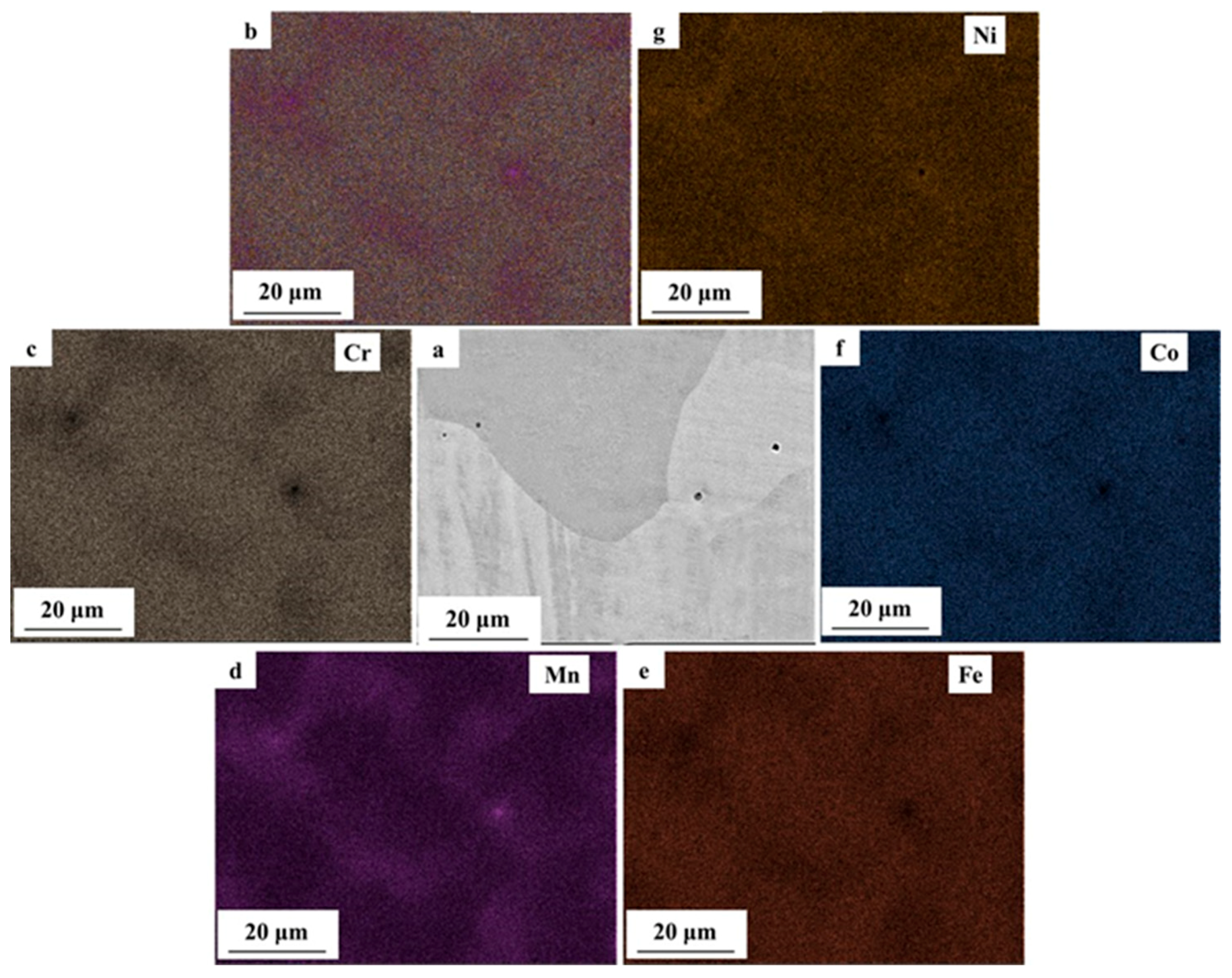
Elemental mapping was conducted by energy-dispersive spectroscopy (EDS) for both AM and as-cast HEAs. Table 2 shows the EDS quantitative analysis of the both alloys, where impurities such as C, N, and O were less than 0.1 at.%. The AM HEA showed uniform distribution of the elements throughout the surface (Figure 7) which may be due to better homogenization from repeated melting or thermal annealing of previous layers during the multi-layer deposition process. The higher pitting resistance of the AM HEA can be attributed to the lower density of large pores and the uniform distribution of Cr, which leads to the formation of a more stable passive film over the surface. In contrast, the as-cast HEA exhibited non-uniform elemental distribution with significant chemical micro-segregation (Figure 8). There were two distinct segregation regions, one with higher Cr, Co, and Fe and the other with higher Mn and Ni. Similar segregation behavior was reported for as-cast CoCrFeMn0.5Ni [40], which is typical for multi-principal element alloys that often have a wide freezing range [41]. The elemental map for the as-cast HEA revealed Cr depleted regions acting as the active sites for corrosion initiation and leading to the formation of non-uniform and less stable passive film. The EDS mapping also confirmed the presence of less Cr content at the micro-pores, which is potentially the main reason for the severe corrosion attack by pitting mechanism on as-cast HEA.
4. Conclusions
In this study, CoCrFeMnNi HEA was additively manufactured by SLM and its corrosion resistance in 3.5 wt% NaCl solution was evaluated by potentiodynamic polarization and electrochemical impedance spectroscopy measurements and compared with the as-cast counterpart. The main conclusions are as follows:
- (1)
- By varying laser power and scan speed, near fully dense CoCrFeMnNi HEA was manufactured by SLM when the VED was in the range of 62.5–115.6 J/mm3. It exhibited a unique non-equilibrium microstructure consisting of tortuous grain boundaries, sub-grain cellular structures, and some processing defects such as micro-pores.
- (2)
- With wider passive region (ΔE), higher polarization resistance (Rp) and pitting potential (Epit), the AM CoCrFeMnNi HEA showed superior corrosion resistance over the as-cast counterpart, which was attributed to the homogeneous elemental distribution at the investigated scale and lower density of micro-pores. The large micro-pores in AM CoCrFeMnNi HEA acted as active anodic sites and prevented nucleation and growth of new pits. The high density of micro-pores in the as-cast alloy resulted in extensive metastable pitting and the micro-segregation regions acted as active sites for corrosion initiation.
Author Contributions
Conceptualization, W.C. and S.M.; Methodology, W.C. and S.M.; Formal analysis, J.R. and C.M.; Investigation, J.R., C.M., L.L. and D.F.; Writing—original draft preparation, J.R. and C.M.; Writing—review and editing, L.L., W.C. and S.M.; Supervision, L.L., W.C. and S.M.; Project administration, W.C. and S.M.
Funding
This research received no external funding.
Acknowledgments
W.C. acknowledges the support by the NASA Marshall Space Flight Center Cooperative Agreement Notice (80MSFC19M0030) and UMass Amherst faculty startup.
Conflicts of Interest
The authors declare no conflict of interest.
References
- Li, Z.M.; Pradeep, K.G.; Deng, Y.; Raabe, D.; Tasan, C.C. Metastable high-entropy dual-phase alloys overcome the strength–ductility trade-off. Nature 2016, 534, 227–230. [Google Scholar] [CrossRef] [PubMed]
- Liang, Y.J.; Wang, L.J.; Wen, Y.R.; Cheng, B.Y.; Wu, Q.L.; Cao, T.Q.; Xiao, Q.; Xue, Y.F.; Sha, G.; Wang, Y.D.; et al. High-content ductile coherent nanoprecipitates achieve ultrastrong high-entropy alloys. Nat. Commun. 2018, 9, 4063. [Google Scholar] [CrossRef] [PubMed]
- Shi, P.J.; Ren, W.L.; Zheng, T.X.; Ren, Z.M.; Hou, X.L.; Peng, J.C.; Hu, P.F.; Gao, Y.F.; Zhong, Y.B.; Liaw, P.K. Enhanced strength–ductility synergy in ultrafine-grained eutectic high-entropy alloys by inheriting microstructural lamellae. Nat. Commun. 2019, 10, 489. [Google Scholar] [CrossRef] [PubMed]
- He, J.Y.; Wang, H.; Huang, H.L.; Xu, X.D.; Chen, M.W.; Wu, Y.; Liu, X.J.; Nieh, T.G.; An, K.; Lu, Z.P. A precipitation-hardened high-entropy alloy with outstanding tensile properties. Acta Mater. 2016, 102, 187–196. [Google Scholar] [CrossRef] [Green Version]
- Ye, Y.F.; Wang, Q.; Lu, J.; Liu, C.T.; Yang, Y. High-entropy alloy: Challenges and prospects. Mater. Today 2016, 19, 349–362. [Google Scholar] [CrossRef]
- Kilmametov, A.; Kulagin, R.; Mazilkin, A.; Seils, S.; Boll, T.; Heilmaier, M.; Hahn, H. High-pressure torsion driven mechanical alloying of CoCrFeMnNi high entropy alloy. Scr. Mater. 2019, 158, 29–33. [Google Scholar] [CrossRef]
- Gludovatz, B.; Hohenwarter, A.; Catoor, D.; Chang, E.H.; George, E.P.; Ritchie, R.O. A fracture-resistant high-entropy alloy for cryogenic applications. Science 2014, 345, 1153–1158. [Google Scholar] [CrossRef] [Green Version]
- Zhang, Z.J.; Mao, M.M.; Wang, J.W.; Gludovatz, B.; Zhang, Z.; Mao, S.X.; George, E.P.; Yu, Q.; Ritchie, R.O. Nanoscale origins of the damage tolerance of the high-entropy alloy CrMnFeCoNi. Nat. Commun. 2015, 6, 10143. [Google Scholar] [CrossRef] [Green Version]
- Shi, Y.Z.; Yang, B.; Liaw, P.K. Corrosion-resistant high-entropy alloys: A review. Metals 2017, 7, 43. [Google Scholar] [CrossRef]
- Tsai, M.H.; Yeh, J.W. High-entropy alloys: A critical review. Mater. Res. Lett. 2014, 2, 107–123. [Google Scholar] [CrossRef]
- Diao, H.Y.; Santodonato, L.J.; Tang, Z.; Egami, T.; Liaw, P.K. Local structures of high-entropy alloys (HEAs) on atomic scales: An overview. JOM 2015, 67, 2321–2325. [Google Scholar] [CrossRef]
- Qiu, Y.; Thomas, S.; Gibson, M.A.; Fraser, H.L.; Birbilis, N. Corrosion of high entropy alloys. NPJ Mater. Degrad. 2017, 1, 15. [Google Scholar] [CrossRef]
- Chou, Y.L.; Yeh, J.W.; Shih, H.C. The effect of molybdenum on the corrosion behaviour of the high-entropy alloys Co1.5CrFeNi1.5Ti0.5Mox in aqueous environments. Corros. Sci. 2010, 52, 2571–2581. [Google Scholar] [CrossRef]
- Kao, Y.F.; Lee, T.D.; Chen, S.K.; Chang, Y.S. Electrochemical passive properties of AlxCoCrFeNi (x = 0, 0.25, 0.50, 1.00) alloys in sulfuric acids. Corros. Sci. 2010, 52, 1026–1034. [Google Scholar] [CrossRef]
- Qiu, X.W.; Liu, C.G. Microstructure and properties of Al2CrFeCoCuTiNix high-entropy alloys prepared by laser cladding. J. Alloy. Compd. 2013, 553, 216–220. [Google Scholar] [CrossRef]
- Hsu, Y.J.; Chiang, W.C.; Wu, J.K. Corrosion behavior of FeCoNiCrCux high-entropy alloys in 3.5% sodium chloride solution. Mater. Chem. Phys. 2005, 92, 112–117. [Google Scholar] [CrossRef]
- Lu, Y.P.; Dong, Y.; Guo, S.; Jiang, L.; Kang, H.J.; Wang, T.M.; Wen, B.; Wang, Z.J.; Jie, J.C.; Cao, Z.Q.; et al. A promising new class of high-temperature alloys: Eutectic high-entropy alloys. Sci. Rep. 2014, 4, 6200. [Google Scholar] [CrossRef]
- Estrin, Y.; Beygelzimer, Y.; Kulagin, R. Design of Architectured Materials Based on Mechanically Driven Structural and Compositional Patterning. Adv. Eng. Mater. 2019, 1900487. [Google Scholar] [CrossRef]
- Thijs, L.; Kempen, K.; Kruth, J.P.; Humbeeck, J.V. Fine-structured aluminium products with controllable texture by selective laser melting of pre-alloyed AlSi10Mg powder. Acta Mater. 2013, 61, 1809–1819. [Google Scholar] [CrossRef] [Green Version]
- Wang, Y.M.; Voisin, T.; McKeown, J.T.; Ye, J.C.; Calta, N.P.; Li, Z.; Zeng, Z.; Zhang, Y.; Chen, W.; Roehling, T.T.; et al. Additively manufactured hierarchical stainless steels with high strength and ductility. Nat. Mater. 2018, 17, 63–71. [Google Scholar] [CrossRef]
- Zhu, Z.G.; Nguyen, Q.B.; Ng, F.L.; An, X.H.; Liao, X.Z.; Liaw, P.K.; Nai, S.M.L.; Wei, J. Hierarchical microstructure and strengthening mechanisms of a CoCrFeNiMn high entropy alloy additively manufactured by selective laser melting. Scr. Mater. 2018, 154, 20–24. [Google Scholar] [CrossRef]
- Sun, Y.; Moroz, A.; Alrbaey, K. Sliding wear characteristics and corrosion behaviour of selective laser melted 316L stainless steel. J. Mater. Eng. Perform. 2014, 23, 518–526. [Google Scholar] [CrossRef]
- Ziętala, M.; Durejko, T.; Polański, M.; Kunce, I.; Płociński, T.; Zieliński, W.; Łazińska, M.; Stępniowski, W.; Czujko, T.; Kurzydłowski, K.J.; et al. The microstructure, mechanical properties and corrosion resistance of 316 L stainless steel fabricated using laser engineered net shaping. Mater. Sci. Eng. A 2016, 677, 1–10. [Google Scholar] [CrossRef]
- Trelewicz, J.R.; Halada, G.P.; Donaldson, O.K.; Manogharan, G. Microstructure and corrosion resistance of laser additively manufactured 316L stainless steel. JOM 2016, 68, 850–859. [Google Scholar] [CrossRef]
- Geenen, K.; Röttger, A.; Theisen, W. Corrosion behavior of 316L austenitic steel processed by selective laser melting, hot-isostatic pressing, and casting. Mater. Corros. 2017, 68, 764–775. [Google Scholar] [CrossRef]
- Kazemipour, M.; Mohammadi, M.; Mfoumou, E.; Nasiri, A.M. Microstructure and corrosion characteristics of selective-laser melted 316L stainless steel: The impact of process-induced porosities. JOM 2019, 71, 3230–3240. [Google Scholar] [CrossRef]
- Dai, N.W.; Zhang, L.C.; Zhang, J.X.; Chen, Q.M.; Wu, M.L. Corrosion behavior of selective laser melted Ti-6Al-4 V alloy in NaCl solution. Corros. Sci. 2016, 102, 484–489. [Google Scholar] [CrossRef]
- Yang, J.J.; Yang, H.H.; Yu, H.C.; Wang, Z.M.; Zeng, X.Y. Corrosion behavior of additive manufactured Ti-6Al-4V alloy in NaCl solution. Metall. Mater. Trans. A 2017, 48, 3583–3593. [Google Scholar] [CrossRef]
- Luo, H.; Li, Z.M.; Mingers, A.M.; Raabe, D. Corrosion behavior of an equiatomic CoCrFeMnNi high-entropy alloy compared with 304 stainless steel in sulfuric acid solution. Corros. Sci. 2018, 134, 131–139. [Google Scholar] [CrossRef]
- Ayyagari, A.; Hasannaeimi, V.; Grewal, H.S.; Arora, H.; Mukherjee, S. Corrosion, erosion and wear behavior of complex concentrated alloys: A review. Metals 2018, 8, 603. [Google Scholar] [CrossRef]
- Ye, Q.F.; Feng, K.; Li, Z.G.; Lu, F.G.; Li, R.F.; Huang, J.; Wu, Y.X. Microstructure and corrosion properties of CrMnFeCoNi high entropy alloy coating. Appl. Surf. Sci. 2017, 396, 1420–1426. [Google Scholar] [CrossRef]
- ASTM International. G102-89 (2015)e1 Standard Practice for Calculation of Corrosion Rates and Related Information from Electrochemical Measurements; American Society for Testing and Materials (ASTM): West Conshohocken, PA, USA, 2015. [Google Scholar]
- Cunningham, R.; Zhao, C.; Parab, N.; Kantzos, C.; Pauza, J.; Fezzaa, K.; Sun, T.; Rollett, A.D. Keyhole threshold and morphology in laser melting revealed by ultrahigh-speed x-ray imaging. Science 2019, 363, 849–852. [Google Scholar] [CrossRef] [PubMed]
- Khairallah, S.A.; Anderson, A.T.; Rubenchik, A.; King, W.E. Laser powder-bed fusion additive manufacturing: Physics of complex melt flow and formation mechanisms of pores, spatter, and denudation zones. Acta Mater. 2016, 108, 36–45. [Google Scholar] [CrossRef] [Green Version]
- Li, R.D.; Niu, P.D.; Yuan, T.C.; Cao, P.; Chen, C.; Zhou, K.C. Selective laser melting of an equiatomic CoCrFeMnNi high-entropy alloy: Processability, non-equilibrium microstructure and mechanical property. J. Alloy. Compd. 2018, 746, 125–134. [Google Scholar] [CrossRef]
- Mukherjee, T.; Zuback, J.S.; De, A.; DebRoy, T. Printability of alloys for additive manufacturing. Sci. Rep. 2016, 6, 19717. [Google Scholar] [CrossRef] [PubMed]
- DuPont, J.N. Fundamentals of weld solidification. In ASM Handbook, Welding Fundamentals and Processes; Lienert, T., Siewert, T., Babu, S., Acoff, V., Eds.; ASM International: Materials Park, OH, USA, 2011; Volume 6A, pp. 96–114. [Google Scholar]
- Shang, X.L.; Wang, Z.J.; He, F.; Wang, J.C.; Li, J.J.; Yu, J.K. The intrinsic mechanism of corrosion resistance for FCC high entropy alloys. Sci. Chin. Technol. Sci. 2018, 61, 189–196. [Google Scholar] [CrossRef]
- Ayyagari, A.; Barthelemy, C.; Gwalani, B.; Banerjee, R.; Scharf, T.W.; Mukherjee, S. Reciprocating sliding wear behavior of high entropy alloys in dry and marine environments. Mater. Chem. Phys. 2018, 210, 162–169. [Google Scholar] [CrossRef]
- Christofidou, K.A.; Pickering, E.J.; Orsatti, P.; Mignanelli, P.M.; Slater, T.J.A.; Stone, H.J.; Jones, N.G. On the influence of Mn on the phase stability of the CrMnxFeCoNi high entropy alloys. Intermetallics 2018, 92, 84–92. [Google Scholar] [CrossRef]
- Flemings, M.C. Solidification processing. Metall. Mater. Trans. B 1974, 5, 2121–2134. [Google Scholar] [CrossRef]
Figure 1.
(a) As-printed samples with different processing parameters; (b) Schematics of scan strategies in selective laser melting process.
Figure 1.
(a) As-printed samples with different processing parameters; (b) Schematics of scan strategies in selective laser melting process.

Figure 2.
Variation of relative density of additively manufactured (AM) CoCrFeMnNi samples with different volume energy densities.
Figure 2.
Variation of relative density of additively manufactured (AM) CoCrFeMnNi samples with different volume energy densities.

Figure 3.
(a) Optical microscopic (OM) cross-section image of gas-atomized CoCrFeMnNi powders with pores inside; (b) SEM cross-section image of a single gas-atomized CoCrFeMnNi powder with needle-like dendrites (after etching) and internal pores. Micro-pores are highlighted by red circles.
Figure 3.
(a) Optical microscopic (OM) cross-section image of gas-atomized CoCrFeMnNi powders with pores inside; (b) SEM cross-section image of a single gas-atomized CoCrFeMnNi powder with needle-like dendrites (after etching) and internal pores. Micro-pores are highlighted by red circles.

Figure 4.
Non-equilibrium microstructure of AM CoCrFeMnNi as-cast sample: (a,b) OM images showing the porosity profile of the side and top surfaces of the AM sample; (c) OM image showing the microstructures of the side surface of the AM sample. The laser melting layers and elongated grains are depicted by white lines and purple arrows, respectively; (d) high magnification OM image showing the heterogeneous microstructures of the side surface of the AM sample. The melt pool boundaries, micro-pores, columnar and equiaxed cellular sub-structures are represented by orange dash lines, blue circles, red and white arrows, respectively; (e) Secondary electrons (SE) mode SEM image showing the melt pool boundaries as well as columnar and equiaxed cellular sub-structures; (f) high magnification SEM image of equiaxed cellular structures.

Figure 5.
(a) Open-circuit potential (EOCP) with respect to saturated calomel electrode (ESCE) as a function of time; (b) cyclic polarization plots at a scan rate of 0.25mV/s; (c) Nyquist plot; and (d) the equivalent circuit used for fitting is shown, where R.E. is the reference electrode, Rs is the solution resistance, Rp is the polarization resistance, C is the constant phase element and W.E. is the working electrode.

Figure 6.
Back scattered electrons(BSE) mode SEM images of CoCrFeMnNi surface before and after cyclic polarization test in 3.5 wt.% NaCl solution: (a) AM HEA (top-surface) before corrosion; (b) AM HEA (top-surface) after corrosion; (c) As-cast HEA before corrosion; (d) As-cast HEA after corrosion. The inset in (b) and (d) are high magnification images.
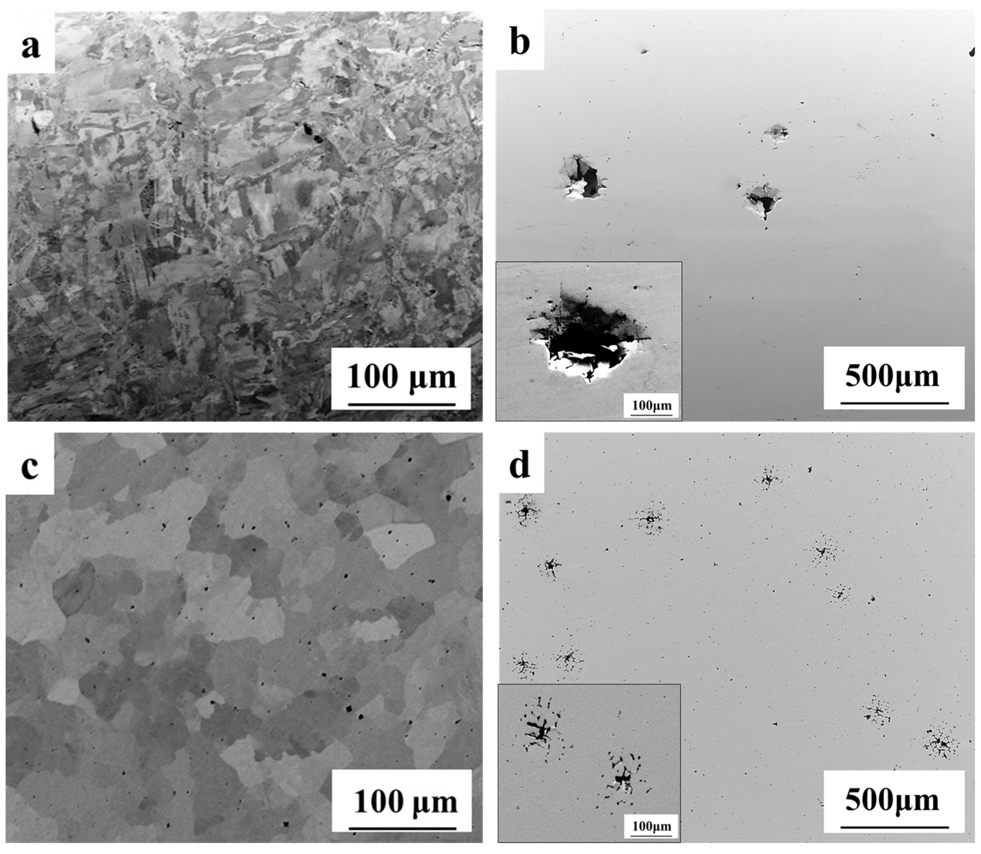
Figure 7.
Energy-dispersive spectroscopy (EDS) map of additive manufactured CoCrFeMnNi HEA surface.

Figure 8.
EDS map of as-cast CoCrFeMnNi HEA surface.


Table 1.
Electrochemical and equivalent circuit parameters for AM and as-cast CoCrFeMnNi alloys in 3.5 wt% NaCl solution.
Table 1.
Electrochemical and equivalent circuit parameters for AM and as-cast CoCrFeMnNi alloys in 3.5 wt% NaCl solution.
| Corrosion Parameter | AM CoCrFeMnNi | As-cast CoCrFeMnNi |
|---|---|---|
| Ecorr (mV) | −189 | −179 |
| Icorr (μA/cm2) | 0.09 | 0.11 |
| Epit (mV) | 197 | 37 |
| ΔEresistance (mV) | 386 | 216 |
| Corrosion Rate (μm/yr) | 0.7304 | 0.909 |
| Polarization resistance, Rp (kilo ohm/cm2) | 278 | 186 |
| Solution resistance, Rs (ohm/cm2) | 5.4 | 5.2 |
| Double Layer Capacitance, C (μF/cm2) | 16.8 | 26 |
Table 2.
EDS quantitative analysis of AM and as-cast CoCrFeMnNi alloy.
| Composition (at. %) | Cr | Mn | Fe | Co | Ni |
|---|---|---|---|---|---|
| AM top surface | 20.61 ± 2.61 | 18.84 ± 2.58 | 20.25 ± 2.8 | 20.52 ± 2.89 | 19.78 ± 3.12 |
| AM side surface | 20.26 ± 2.63 | 18.35 ± 2.59 | 20.41 ± 2.76 | 20.93 ± 2.88 | 20.06 ± 3.13 |
| As-cast | 19.32 ± 2.2 | 19.89 ± 2.03 | 20.74 ± 2.2 | 20.22 ± 2.29 | 19.83 ± 2.47 |
© 2019 by the authors. Licensee MDPI, Basel, Switzerland. This article is an open access article distributed under the terms and conditions of the Creative Commons Attribution (CC BY) license (http://creativecommons.org/licenses/by/4.0/).
Share and Cite
MDPI and ACS Style
Ren, J.; Mahajan, C.; Liu, L.; Follette, D.; Chen, W.; Mukherjee, S. Corrosion Behavior of Selectively Laser Melted CoCrFeMnNi High Entropy Alloy. Metals 2019, 9, 1029. https://doi.org/10.3390/met9101029
AMA Style
Ren J, Mahajan C, Liu L, Follette D, Chen W, Mukherjee S. Corrosion Behavior of Selectively Laser Melted CoCrFeMnNi High Entropy Alloy. Metals. 2019; 9(10):1029. https://doi.org/10.3390/met9101029
Chicago/Turabian StyleRen, Jie, Chaitanya Mahajan, Liang Liu, David Follette, Wen Chen, and Sundeep Mukherjee. 2019. "Corrosion Behavior of Selectively Laser Melted CoCrFeMnNi High Entropy Alloy" Metals 9, no. 10: 1029. https://doi.org/10.3390/met9101029
Note that from the first issue of 2016, this journal uses article numbers instead of page numbers. See further details here.