Chemical Stability of Zirconolite for Proliferation Resistance under Conditions Typically Required for the Leaching of Highly Refractory Uranium Minerals

Abstract
:1. Introduction
2. Materials and Methods
2.1. Sample Preparation
2.2. Sample Characterisation
2.3. Leaching Study
3. Results and Discussion
3.1. Feed Characterisation
3.1.1. Feed Assays
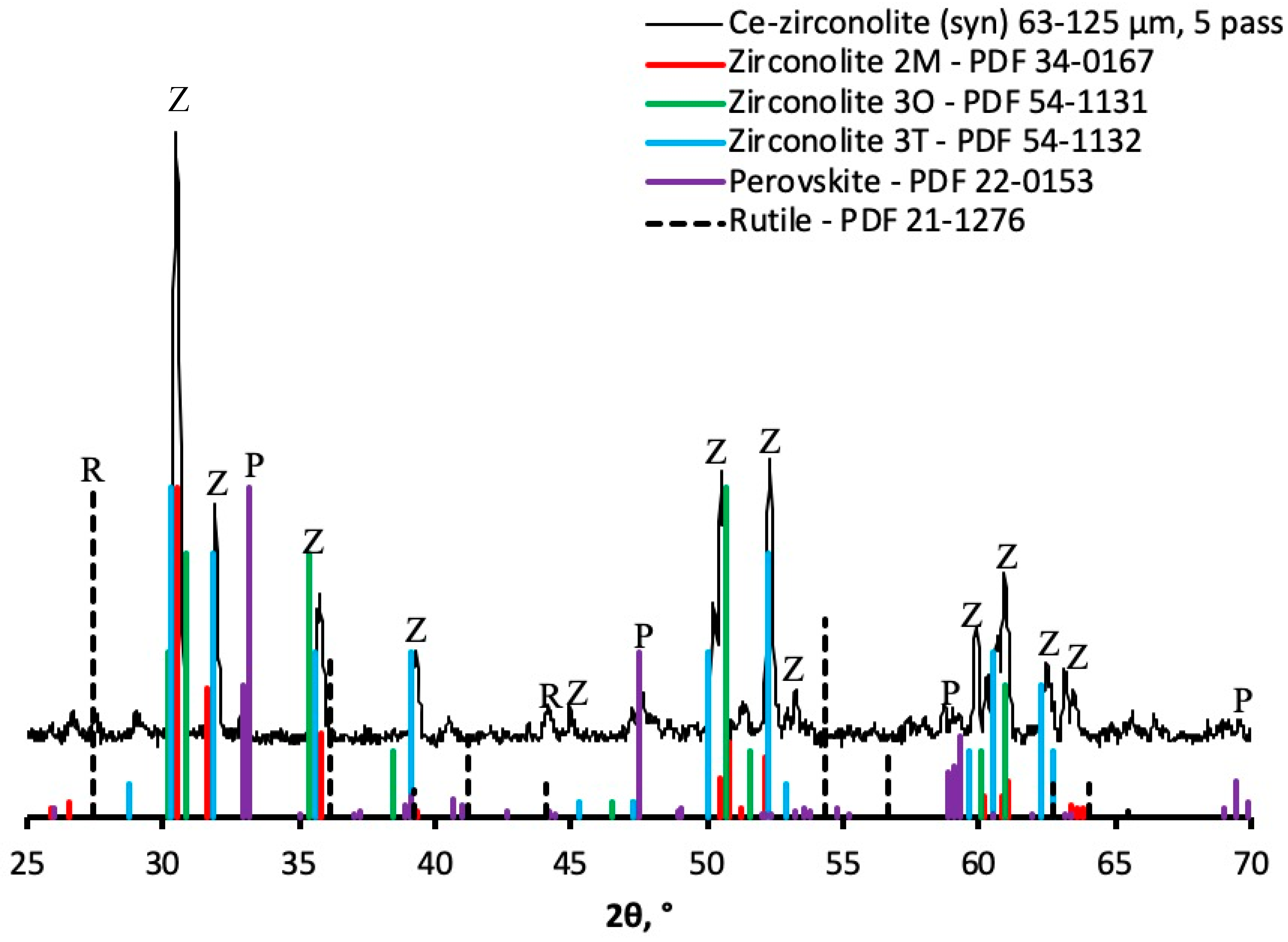
3.1.2. XRD
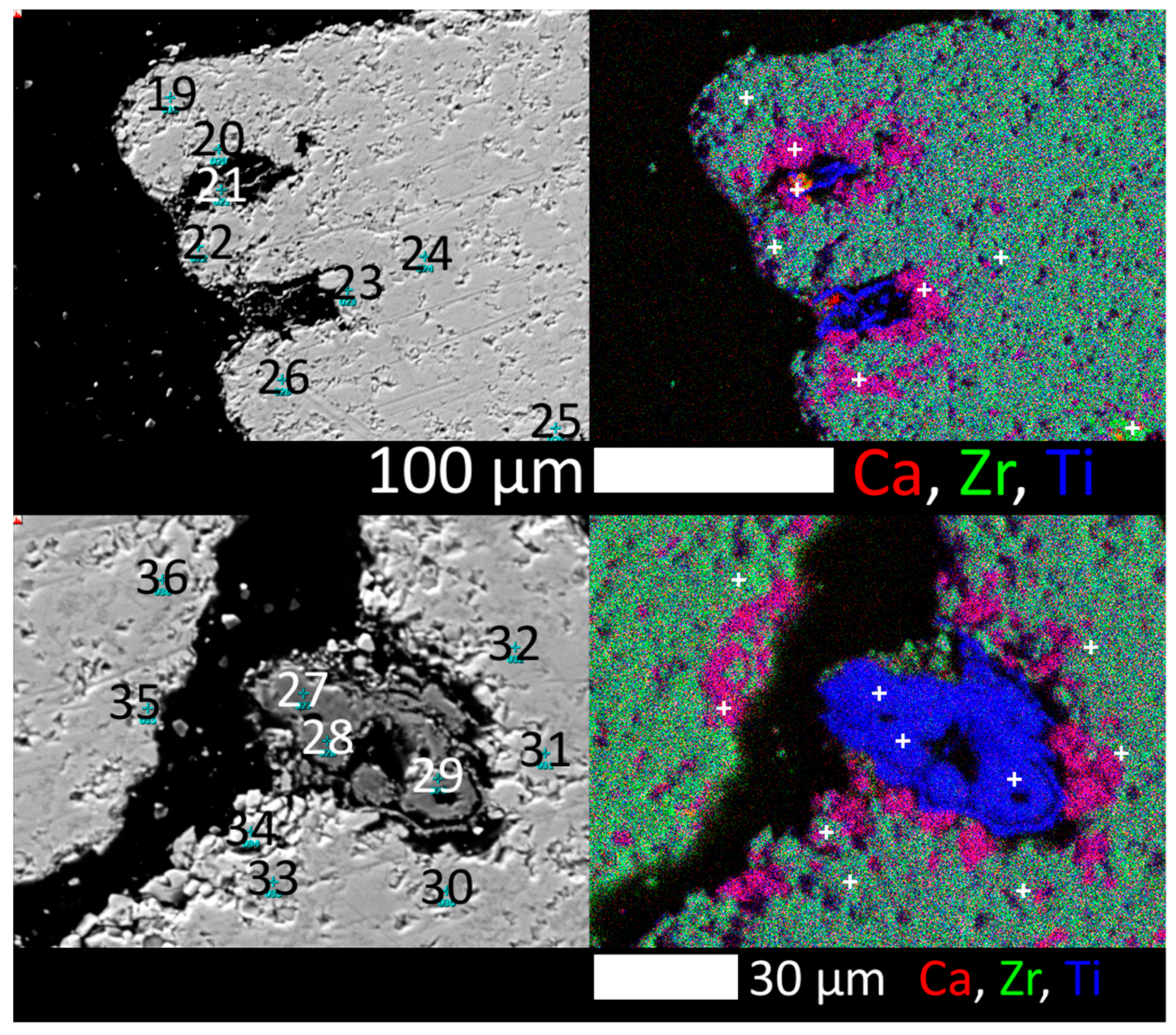
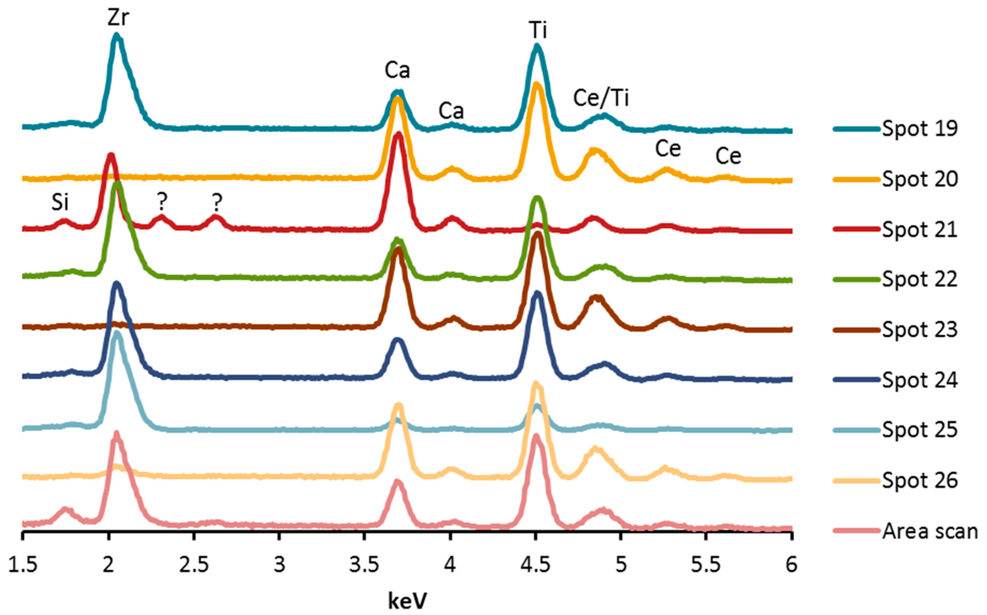
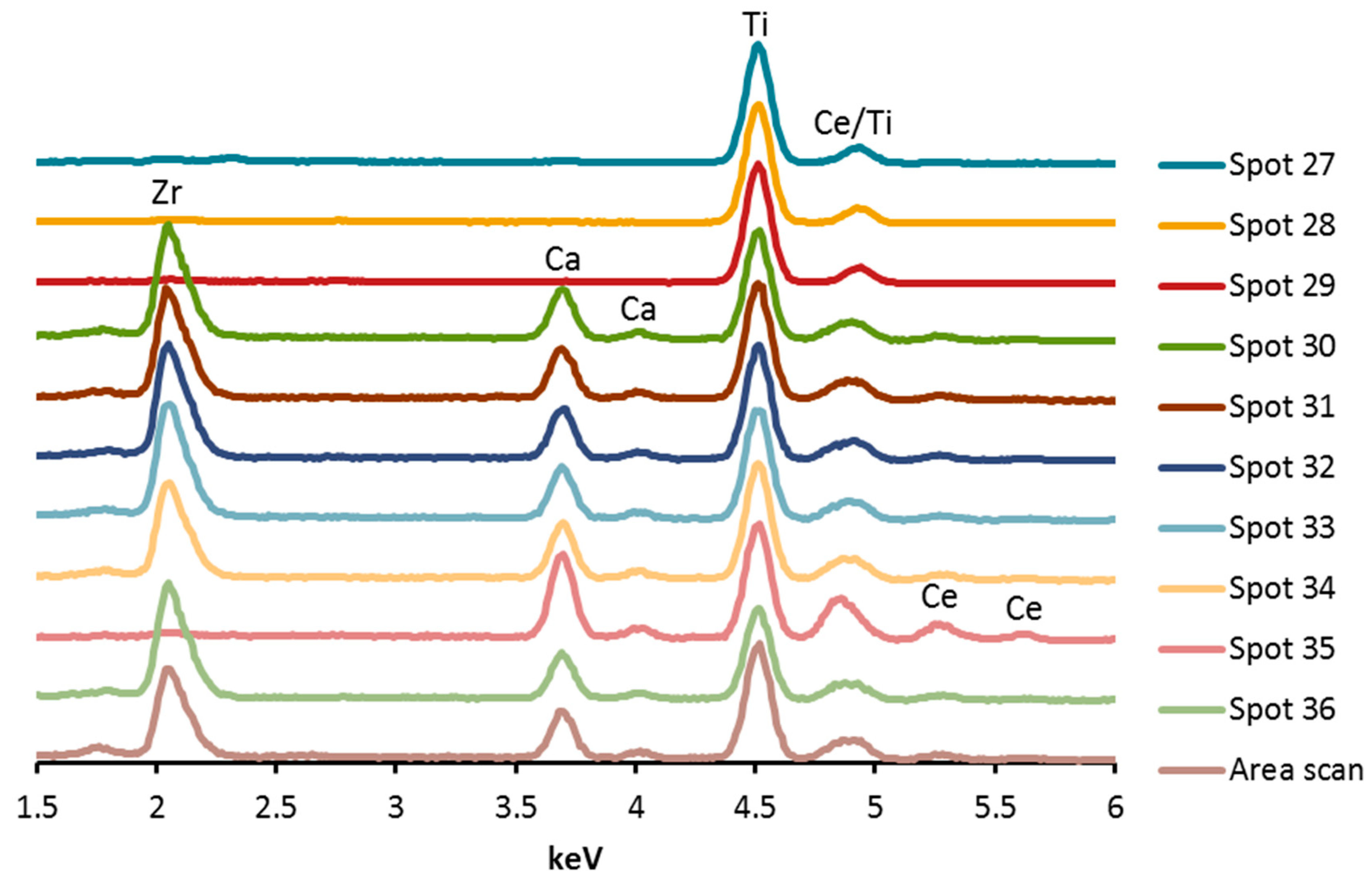
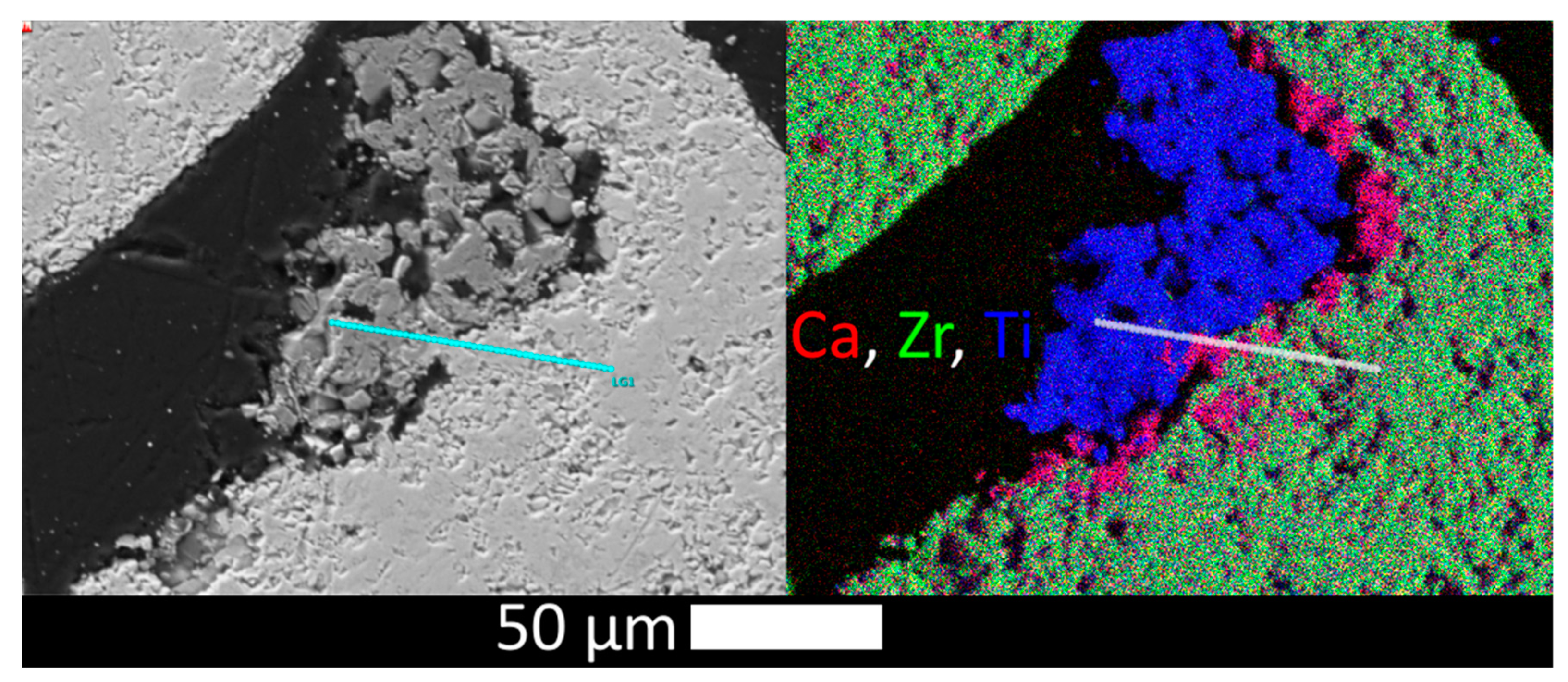
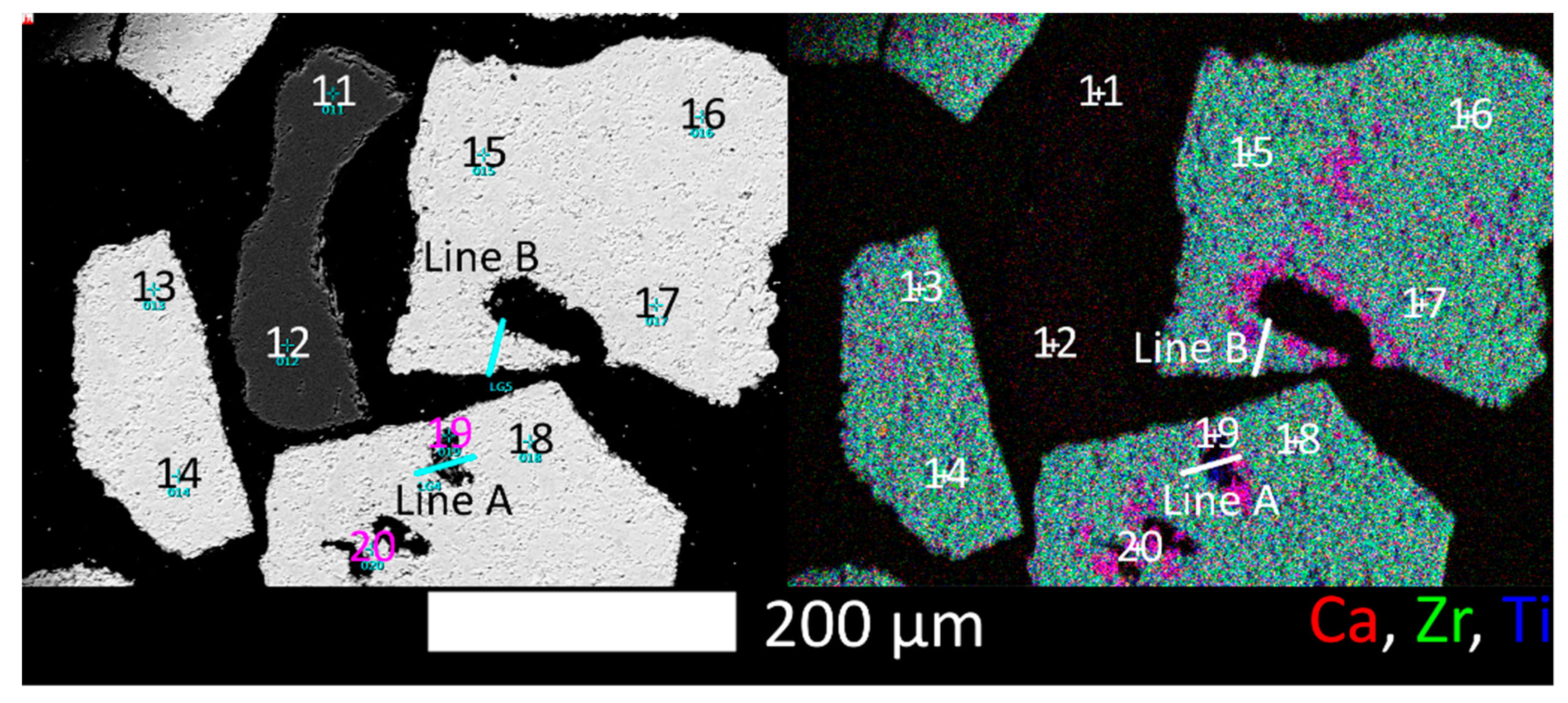
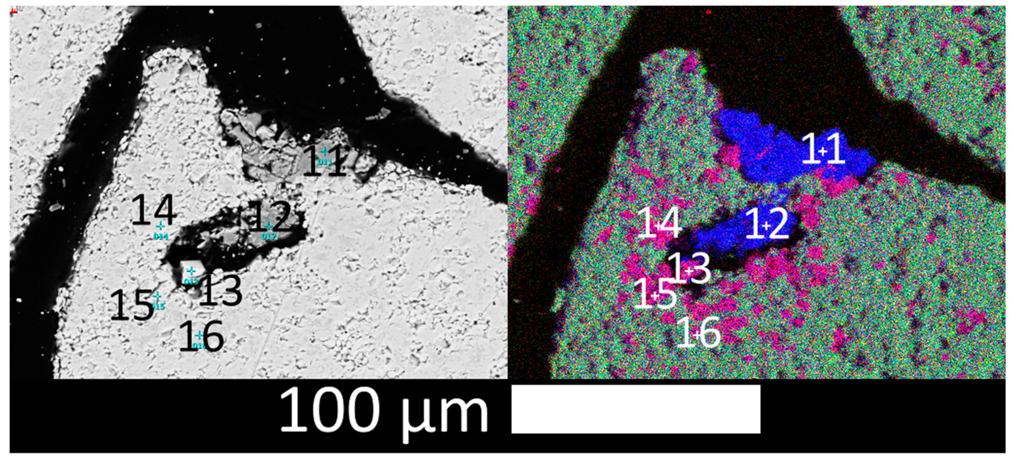
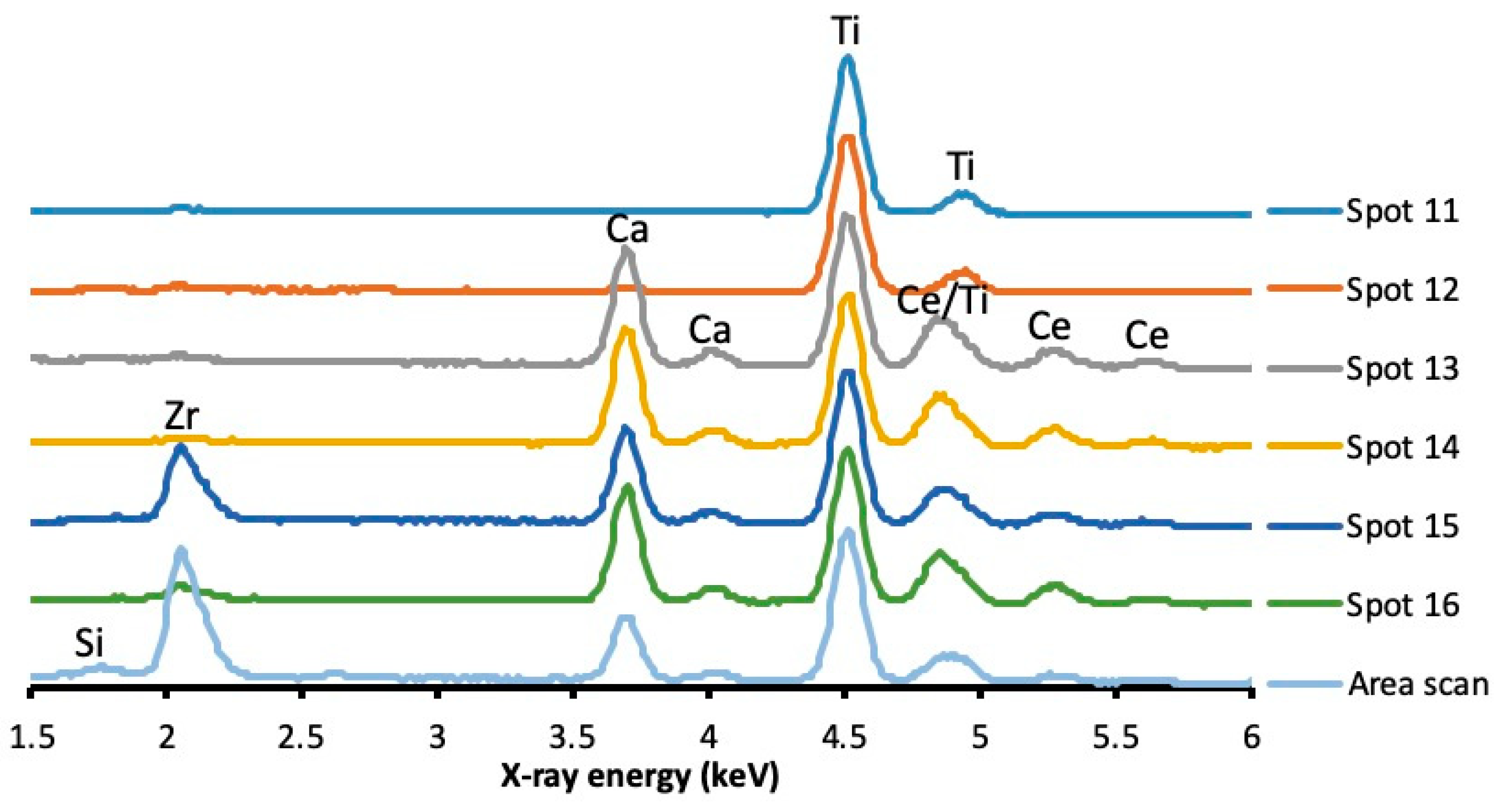
3.1.3. SEM, EDX
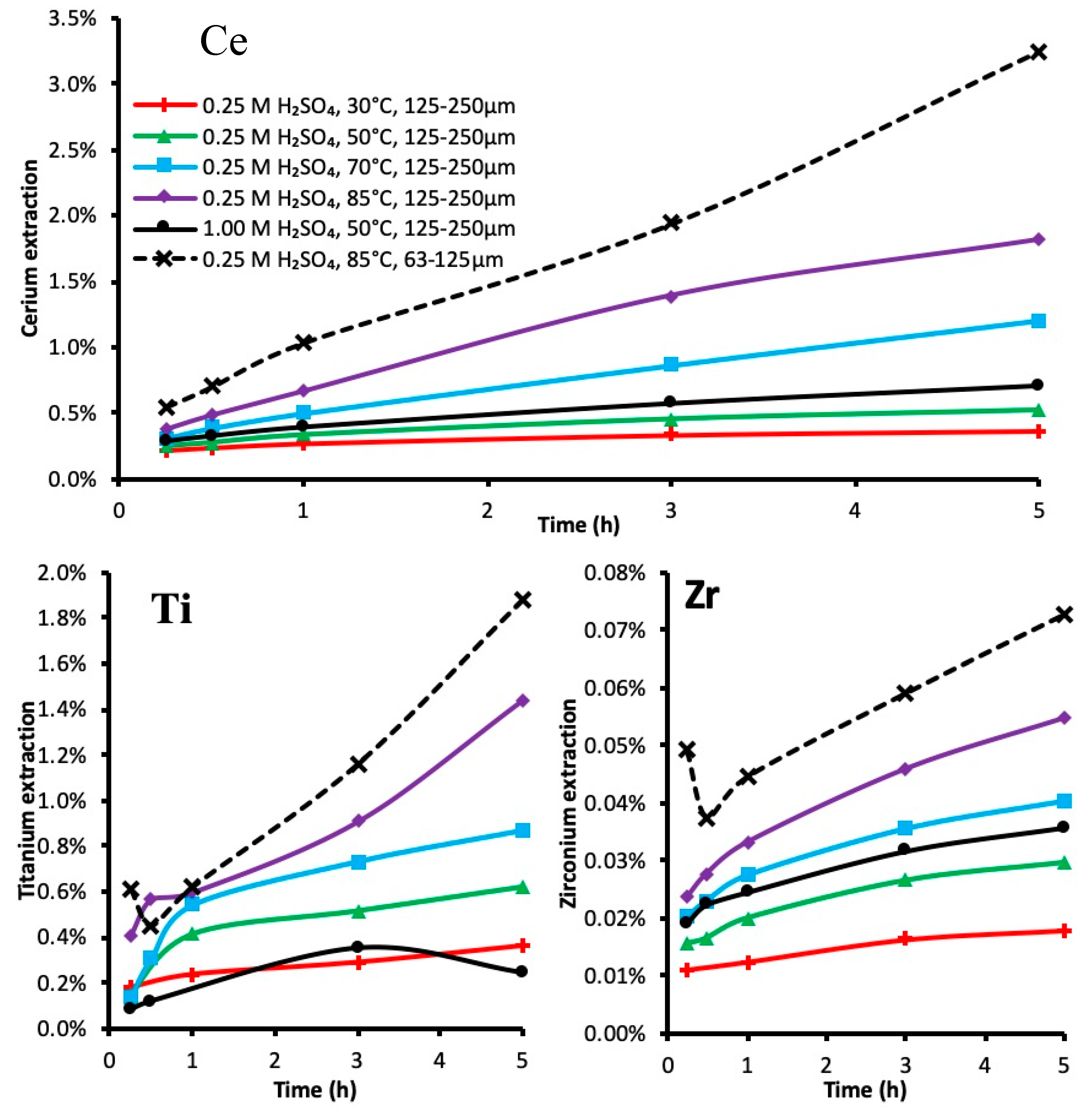
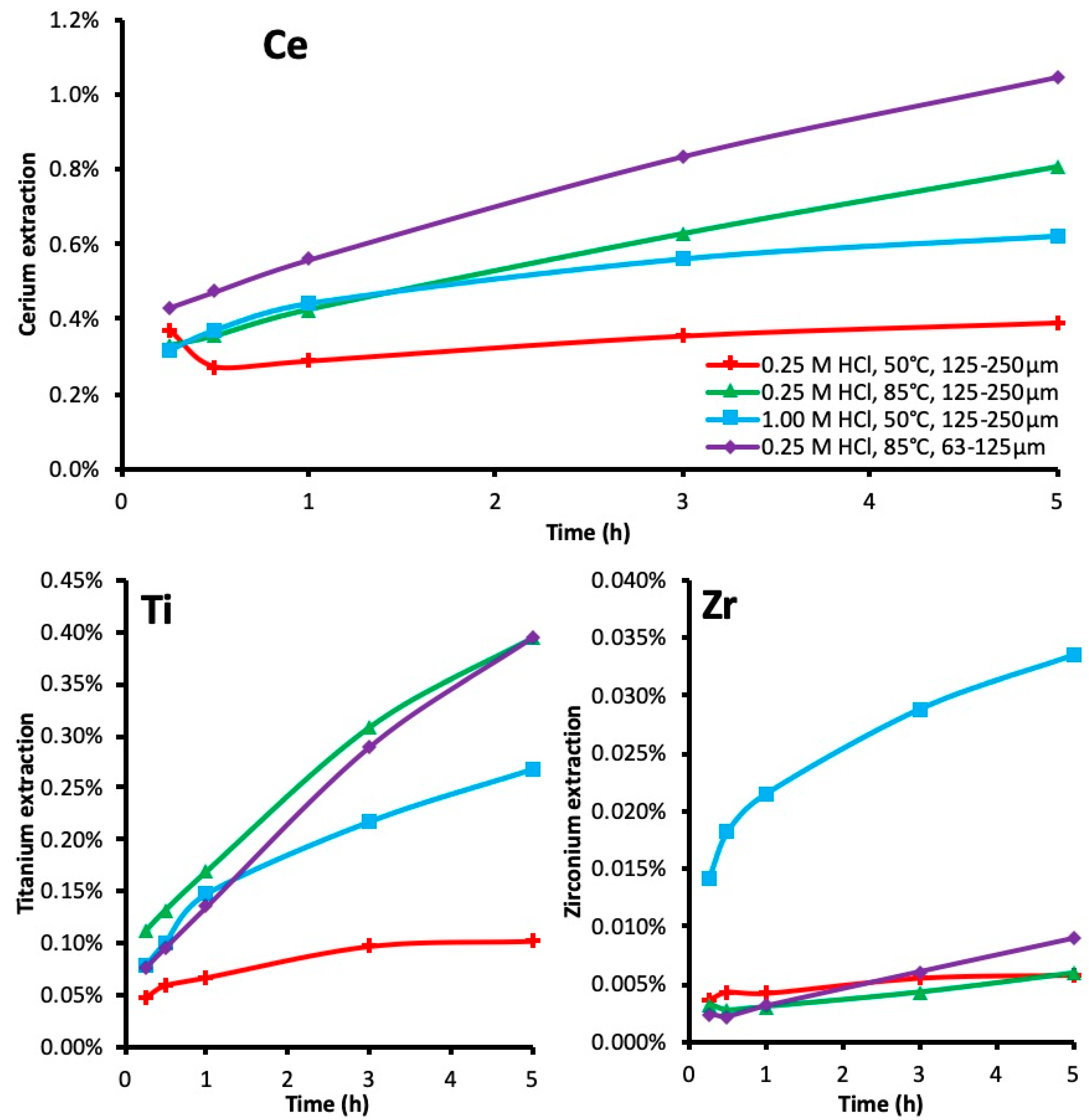
3.2. Leaching Kinetics
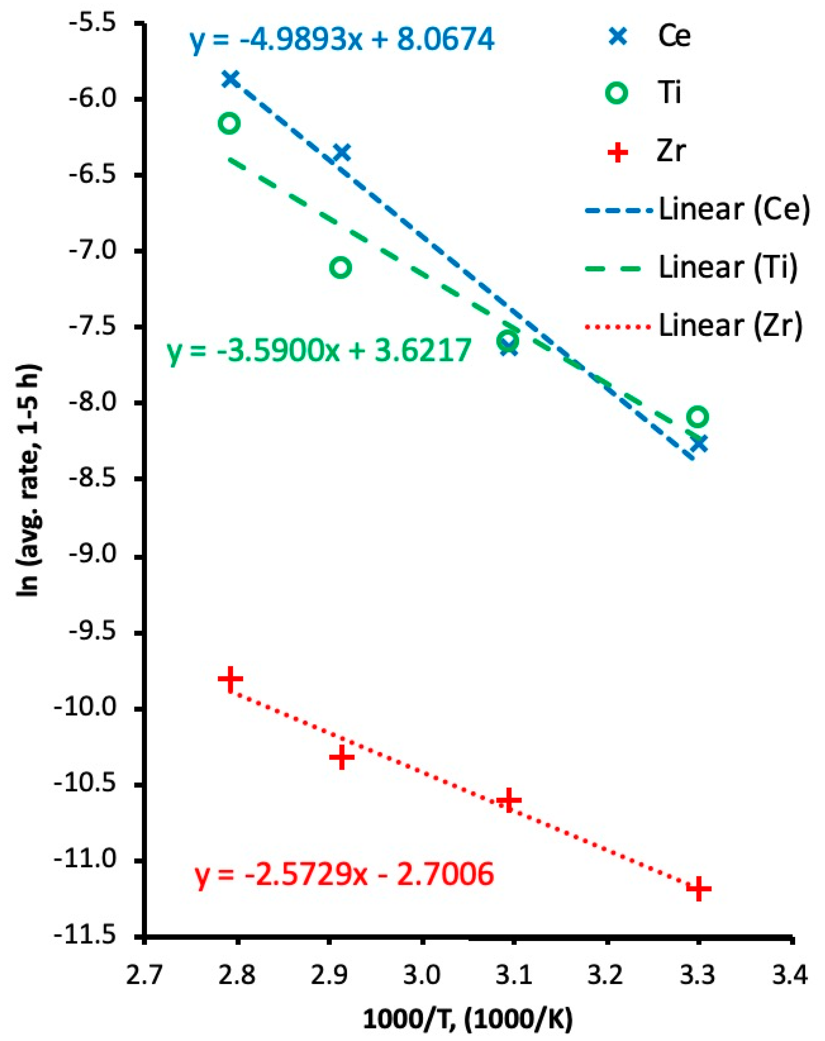
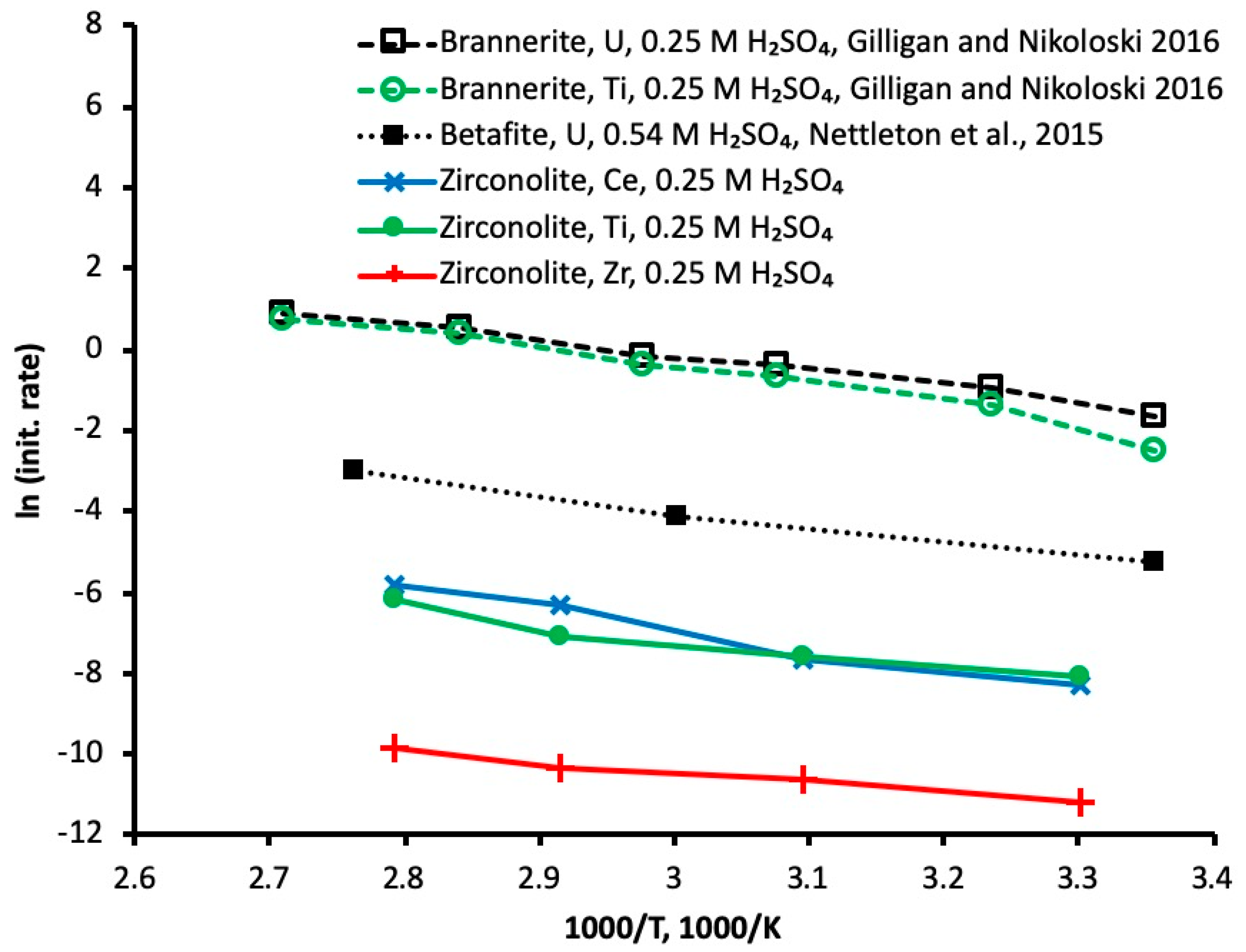
3.3. Activation Energy
3.4. Leached Residue Characterisation
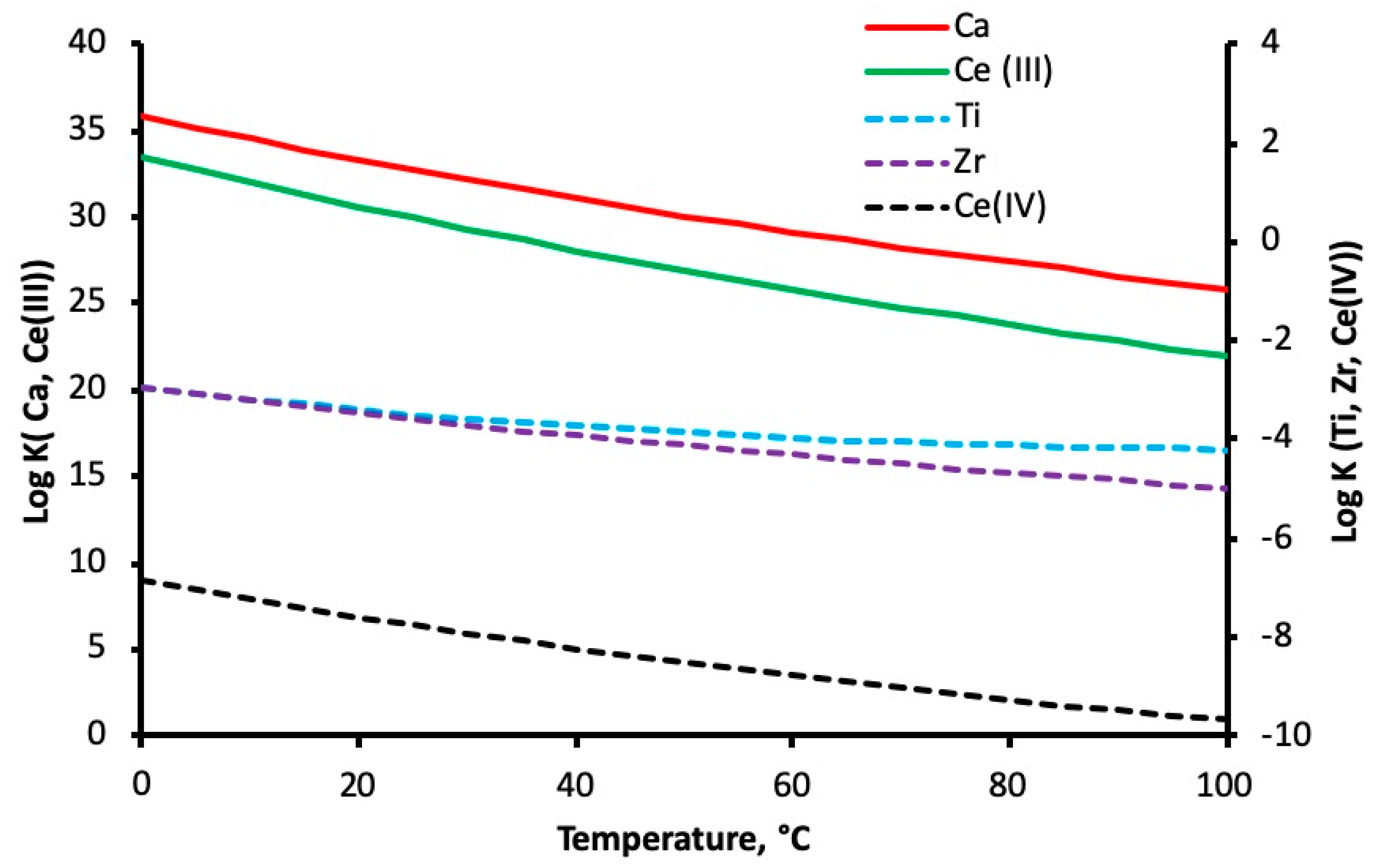
3.5. Reaction Mechanisms
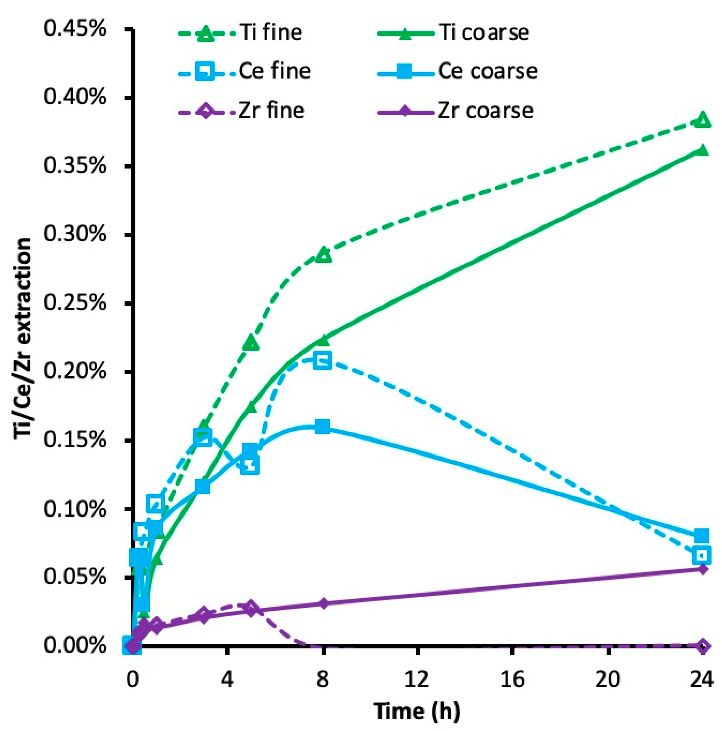
3.6. Crystallinity and Leachability
4. Conclusions
Author Contributions
Funding
Acknowledgments
Conflicts of Interest
References
- Lumpkin, G.R. Ceramic waste forms for actinides. Elements 2006, 2, 365–372. [Google Scholar] [CrossRef]
- Lumpkin, G.R. Alpha-decay damage and aqueous durability of actinide host phases in natural systems. J. Nucl. Mater. 2001, 289, 136–166. [Google Scholar] [CrossRef]
- Gieré, R.; Williams, C.T. REE-bearing minerals in a Ti-rich vein from the Adamello contact aureole (Italy). Contrib. Min. Pet. 1992, 112, 83–100. [Google Scholar]
- De Hoog, J.C.M.; van Bergen, M.J. Notes on the chemical composition of zirconolite with thorutite inclusions from Walaweduwa, Sri Lanka. Mineral. Mag. 1997, 61, 721–725. [Google Scholar] [CrossRef]
- Rasmussen, B.; Fletcher, I.R. Zirconolite: A new U-Pb chronometer for mafic igneous rocks. Geology 2004, 32, 785–788. [Google Scholar] [CrossRef]
- Seddio, S.M.; Jolliff, B.L.; Korotev, R.L.; Zeigler, R.A. Petrology and geochemistry of lunar granite 12032, 366–19 and implications for lunar granite petrogenesis. Am. Mineral. 2013, 98, 1697–1713. [Google Scholar] [CrossRef]
- Gieré, R.; Williams, C.T.; Lumpkin, G.R. Chemical characteristics of natural zirconolite. Schweiz. Miner. Petrogr. Mitt. 1998, 78, 433–459. [Google Scholar]
- Helean, K.B.; Navrotsky, A.; Vance, E.R.; Carter, B.; Ebbinghaus, B.; Krikorian, O.; Lian, J.; Wang, L.M.; Catalano, J.G. Enthalpies of formation of Ce-pyrochlore, Ca0.93Ce1.00Ti2.035O7.00, U-pyrochlore, Ca1.46U4+0.23U6+0.46Ti1.85O7.00 and Gd-pyrochlore, Gd2Ti2O7: Three materials relevant to the proposed waste form for excess weapons plutonium. J. Nucl. Mater. 2002, 303, 226–239. [Google Scholar] [CrossRef]
- Gilligan, R.; Nikoloski, A.N. Leaching of brannerite in the ferric sulphate system. Part 1: Kinetics and reaction mechanism. Hydrometallurgy 2015, 156, 71–80. [Google Scholar] [CrossRef]
- Gilligan, R.; Nikoloski, A.N. Leaching of brannerite in the ferric chloride system. Hydrometallurgy 2018, 180, 104–112. [Google Scholar] [CrossRef]
- Nettleton, K.C.A.; Nikoloski, A.N.; Da Costa, M. The leaching of uranium from betafite. Hydrometallurgy 2015, 157, 270–279. [Google Scholar] [CrossRef] [Green Version]
- Gilligan, R.; Nikoloski, A.N. Alkaline leaching of brannerite. Part 1: Kinetics, reaction mechanisms and mineralogical transformations. Hydrometallurgy 2017, 169, 399–410. [Google Scholar] [CrossRef]
- Williams, C.T. The occurrence of niobian zirconolite, pyrochlore and baddeleyite in the Kovdor carbonatite complex, Kola Peninsula, Russia. Mineral. Mag. 1996, 60, 639–646. [Google Scholar] [CrossRef]
- Pöml, P.; Geisler, T.; Cobos-Sabaté, J.; Wiss, T.; Raison, P.E.; Schmid-Beurmann, P.; Deschanels, X.; Jégou, C.; Heimink, J.; Putnis, A. The mechanism of the hydrothermal alteration of cerium- and plutonium-doped zirconolite. J. Nucl. Mater. 2011, 410, 10–23. [Google Scholar] [CrossRef]
- Bellatreccia, F.; Della Ventura, G.; Williams, C.T.; Lumpkin, G.R.; Smith, K.L.; Colella, M. Non-metamict zirconolite polytypes from the feldspathoid-bearing alkalisyenitic ejecta of the Vico volcanic complex (Latium, Italy). Eur. J. Mineral. 2002, 14, 809–820. [Google Scholar] [CrossRef]
- Bellatreccia, F.; Della Ventura, G.; Caprilli, E.; Williams, C.T.; Parodi, G.C. Crystal-chemistry of zirconolite and calzirtite from Jacupiranga, São Paulo (Brazil). Mineral. Mag. 1999, 63, 649–660. [Google Scholar] [CrossRef]
- White, T.J.; Segall, R.L.; Hutchison, J.L.; Barry, J.C. Polytypic behaviour of zirconolite. Proc. R. Soc. Lond. A 1984, 392, 343–358. [Google Scholar] [CrossRef]
- Reed, S.J.N. Electron Microprobe Analysis and Scanning Electron Microscopy in Geology, 2nd ed.; Cambridge University: Cambridge, UK, 2008. [Google Scholar]
- Chang, L.L.; Howie, R.A.; Zussman, J. Rock-Forming Minerals: Volume 5. Non-Silicates; Deer, W.A., Howie, R.A., Zussman, J., Eds.; Longman: London, UK, 1975. [Google Scholar]
- Wenk, H.R.; Bulakh, A.G. Minerals, Their Constitution and Origin; Cambridge University Press: Cambridge, UK, 2004. [Google Scholar]
- Lumpkin, G.R.; Smith, K.L.; Blackford, M.G. Partitioning of uranium and rare earth elements in Synroc: Effect of impurities, metal additive, and waste loading. J. Nucl. Mater. 1995, 224, 31–42. [Google Scholar] [CrossRef]
- Gilligan, R.; Deditius, A.P.; Nikoloski, A.N. Leaching of brannerite in the ferric sulphate system. Part 2: Mineralogical transformations during leaching. Hydrometallurgy 2016, 159, 95–106. [Google Scholar] [CrossRef] [Green Version]
- Charalambous, F.A.; Ram, R.; Pownceby, M.I.; Tardio, J.; Bhargava, S.K. Chemical and microstructural characterisation studies on natural and heat treated brannerite samples. Miner. Eng. 2012, 39, 276–288. [Google Scholar] [CrossRef]
- McMaster, S.A.; Ram, R.; Pownceby, M.I.; Tardio, J.; Bhargava, S.K. Characterisation and leaching studies on the uranium mineral betafite [(U,Ca)2(Nb,Ti,Ta)2O7]. Miner. Eng. 2015, 81, 58–70. [Google Scholar] [CrossRef]
- McMaster, S.A.; Ram, R.; Faris, N.; Pownceby, M.I.; Tardio, J.; Bhargava, S.K. Uranium leaching from synthetic betafite: [(Ca,U)2(Ti,Nb,Ta)2O7]. Int. J. Miner. Process. 2017, 160, 58–67. [Google Scholar] [CrossRef]
- Strachan, D.M.; Scheele, R.D.; Icenhower, J.P.; Buck, E.C.; Kozelisky, A.E.; Sell, R.L.; Elovich, R.J.; Buchmiller, W.C. Radiation Damage Effects in Candidate Ceramics for Plutonium Immobilization; Final Report, PNNL-14588; Pacific Northwest National Laboratory: Richland, WA, USA, 2004.
- Roinne, A. SC Chemistry Software, version 7.1.1; Chemical Reaction and Equilibrium Modules. Outotec Research: Pori, Finland, 2012. [Google Scholar]
- Gilligan, R.; Nikoloski, A.N. Alkaline leaching of brannerite. Part 2: Leaching of a high-carbonate refractory uranium ore. Hydrometallurgy 2017, 173, 224–231. [Google Scholar] [CrossRef]
- Knauss, K.G.; Dibley, M.J.; Bourcier, W.L.; Shaw, H.F. Ti(IV) hydrolysis constants derived from rutile solubility measurements made from 100 to 300 °C. Appl. Geochem. 2001, 16, 1115–1128. [Google Scholar] [CrossRef]
- Schmidt, J.; Vogelsberger, W. Aqueous Long-Term Solubility of Titania Nanoparticles and Titanium (IV) Hydrolysis in a Sodium Chloride System Studied by Adsorptive Stripping Voltammetry. J. Solut. Chem. 2009, 38, 1267–1282. [Google Scholar] [CrossRef]
- Thompson, J.V. Titanium pigments from Colorado perovskite. In Proceedings of the SME Annual Meeting, Salt Lake City, UT, USA, 26 February–1 March 1990. [Google Scholar]
- Gupta, C.K. Chemical Metallurgy: Principles and Practice; John Wiley & Sons: Weinheim, Germany, 2003. [Google Scholar]
- Zhang, Y.; Hart, K.P.; Bourcier, W.L.; Day, R.A.; Colella, M.; Thomas, B.; Aly, Z.; Jostsons, A. Kinetics of uranium release from Synroc phases. J. Nucl. Mater. 2001, 289, 254–262. [Google Scholar] [CrossRef]
- Gilligan, R. The Extractive Metallurgy of Brannerite: Leaching Kinetics, Reaction Mechanisms and Mineralogical Transformations. Ph.D. thesis, Murdoch University, Perth, Australia, 2017. [Google Scholar]
- Langmuir, D. Aqueous Environmental Geochemistry; Prentice Hall: Portland, ME, USA, 1997. [Google Scholar]
- Pabst, A. The metamict state. Am. Mineral. 1952, 37, 137–157. [Google Scholar]
- Ebbinghaus, B.B.; Armantrout, G.A.; Gray, L.; Herman, C.C.; Shaw, H.F.; Van Konynenburg, R.A. Plutonium Immobilization Project Baseline Formulation; Lawrence Livermore National Laboratory: Livermore, CA, USA, 2000; UCRL-ID-133089, rev. 1. PIP-00-141.


| Lixiviant | Temperature (°C) | Lixiviant Concentration (mol/L) | Size Range (μm) | Duration (h) |
|---|---|---|---|---|
| HCl | 50 | 0.25 | 125–250 | 5 |
| HCl | 85 | 0.25 | 125–250 | 5 |
| HCl | 50 | 1.00 | 125–250 | 5 |
| HCl | 85 | 0.25 | 63–125 | 5 |
| H2SO4 | 30 | 0.25 | 125–250 | 5 |
| H2SO4 | 50 | 0.25 | 125–250 | 5 |
| H2SO4 | 70 | 0.25 | 125–250 | 5 |
| H2SO4 | 85 | 0.25 | 125–250 | 5 |
| H2SO4 | 50 | 1.00 | 125–250 | 5 |
| H2SO4 | 85 | 0.25 | 63–125 | 5 |
| NaHCO3, Na2CO3 | 70 | 0.67, 0.33 | 125–250 | 24 |
| NaHCO3, Na2CO3 | 70 | 0.67, 0.33 | 63–125 | 24 |
| Element | Coarse Zirconolite | Fine Zirconolite |
|---|---|---|
| Zr | 25.88% | 25.54% |
| Ti | 25.75% | 25.68% |
| Ce | 8.20% | 8.12% |
| Ca | 7.83% | 7.88% |
| Hf | 0.63% | 0.63% |
| Si | 0.19% | 0.25% |
| Element | Coarse Zirconolite | Fine Zirconolite |
|---|---|---|
| Na | 800 | 900 |
| Ag | 707 | 849 |
| Nb | 650 | 620 |
| Fe | 475 | 645 |
| Mg | 355 | 420 |
| S | 350 | 400 |
| Al | 280 | 430 |
| P | 245 | 240 |
| Ga | 240 | 275 |
| K | 200 | 300 |
| Element | H2SO4 | HCl |
|---|---|---|
| Ce | 41.5 | 35.5 |
| Ti | 29.8 | 50.2 |
| Zr | 21.4 | 15.4 |
© 2019 by the authors. Licensee MDPI, Basel, Switzerland. This article is an open access article distributed under the terms and conditions of the Creative Commons Attribution (CC BY) license (http://creativecommons.org/licenses/by/4.0/).
Share and Cite
Nikoloski, A.N.; Gilligan, R.; Squire, J.; Maddrell, E.R. Chemical Stability of Zirconolite for Proliferation Resistance under Conditions Typically Required for the Leaching of Highly Refractory Uranium Minerals. Metals 2019, 9, 1070. https://doi.org/10.3390/met9101070
Nikoloski AN, Gilligan R, Squire J, Maddrell ER. Chemical Stability of Zirconolite for Proliferation Resistance under Conditions Typically Required for the Leaching of Highly Refractory Uranium Minerals. Metals. 2019; 9(10):1070. https://doi.org/10.3390/met9101070
Chicago/Turabian StyleNikoloski, Aleksandar N., Rorie Gilligan, Jonathan Squire, and Ewan R. Maddrell. 2019. "Chemical Stability of Zirconolite for Proliferation Resistance under Conditions Typically Required for the Leaching of Highly Refractory Uranium Minerals" Metals 9, no. 10: 1070. https://doi.org/10.3390/met9101070