Article

Effects of Al2O3 Addition on the Microstructure and Properties of CoCr Alloys

College of Materials Science and Engineering, North University of China, Taiyuan 030051, China
*
Author to whom correspondence should be addressed.
Metals 2019, 9(10), 1074; https://doi.org/10.3390/met9101074
Submission received: 1 September 2019 / Revised: 17 September 2019 / Accepted: 24 September 2019 / Published: 2 October 2019

Abstract

:
Aluminum oxide (Al2O3) powder can be added to typical cobalt-chromium (CoCr) alloy powders. In the present study, we successfully prepared alloyed samples of various powder ratios by laser cladding and analyzed their microstructure and carbide structural characteristics, including the microhardness, biological properties, morphology (using scanning electron microscopy), and crystal structure (using X-ray powder diffraction). The elemental distribution was also determined by energy-dispersive X-ray spectroscopy. The results showed that an Al2O3 addition caused the alloy microstructure to change from slender columnar crystals to columnar grains that were similar in shape to equiaxed grains. In addition, Al2O3 agglomeration zones appeared, and carbide structures were altered. The mechanism of the observed performance changes was also analyzed.

1. Introduction

The development of dental restoration has always been closely related to the progress of oral materials. Finding the most suitable materials and manufacturing techniques has always been the interest of dentists. In recent years, the use of all-ceramic restorations has been increasing in terms of oral repair materials, but their application has been impaired due to their high melting point and hardness, which impedes machining in terms of cutting and plasticity [1]. Therefore, metal-based medical materials are currently the first choice of dental prosthetic materials [2]. Cobalt-chromium (CoCr) alloys are cost-effective and demonstrate good physical and mechanical properties and good biocompatibility [3,4,5,6]. They are therefore used in a wide range of applications in the oral repair field and remain one of the most commonly used materials in clinical practice.
CoCr alloys have been the focus of many studies. For example, Quante [7,8,9] et al. studied the effect of different manufacturing methods on the metal-ceramic bond strength. They found that the metal-ceramic bond strength of metal liners produced by 3D printing was effectively improved and that the alloy properties were better than those of alloys produced by casting [7,8,9]. Hedberg [10] et al. found that the rapid cooling during the selective laser melting (SLM) technique led to the formation of a molybdenum (Mo)-rich phase in medical cobalt-chromium (CoCr) Mo alloys. A large proportion of hexagonal close-packed Cr23C6 particle phases were formed on the surface, effectively reducing the ion release of the alloy, and the special texture of the molten pool changed the corrosion resistance of these materials. Second-phase particles with a size of <10 μm were found to effectively improve CoCrMo alloy mechanical properties [11,12].
In addition, in the processing of CoCr alloys, their microstructure and properties under different processes have been extensively studied [2,13,14,15,16,17,18], including a large number of studies on heat treatment processes and surface modification of CoCr alloys [19,20,21,22,23]. Cast CoCr alloys with coarse microstructures and solidification defects have been reported [24]. One of the major advantages of SLM, compared to those of foundry approaches, is that the grain size of CoCr alloys prepared with this technique is small. To date, there have been few studies on the preparation of CoCr alloys by laser cladding.
In recent years, an increasing number of studies have been performed on the preparation of metallic materials by laser cladding, and it has been found that the manufacturing accuracy is basically the same as that of SLM [25]. Our present study uses laser cladding to make alloy materials and provide additional methods for denture production because of the small dentures that laser cladding provides.
Microalloying has always been a hot topic in material research. Allowing microalloyed elements to fully exert their strengthening effects is a function of the alloy and the elemental additions. Few studies have focused on the use of carbides for the modification of CoCr alloy powders. Al2O3 is the main material commonly used for blasting CoCr alloys [26,27]. Hagihara [28] et al. found that Al2O3 addition results in a significant change in the structure of single crystals during directional solidification of CoCr alloys, ultimately increasing the alloy strength. The main goal of the present study was to further examine the modification of CoCr powder by the addition of Al2O3 powder. Original and modified powders were processed by single laser cladding forming, and their phases and microstructures were characterized by scanning electron microscopy (SEM) and X-ray powder diffraction (XRD). The mechanical properties of the two samples were also tested and compared to those of a traditional CoCr alloy carbide in terms of the alloy morphology and mechanical properties. This study provides a theoretical and technical reference for the modification of existing CoCr powder materials.

2. Materials and Methods

The CoCr alloy used in this experiment was a CoCr-0404 alloy powder produced by Renishaw Co, Inc. (Gloucestershire, UK). The mass fractions of Cr, Mo, Si, Mn, Fe, and C were 29.5%, 5.3%, 0.7%, 0.5%, 0.4%, and 1.2%, respectively. The powder had particle sizes that ranged from 10.3 to 31.2 µm, a density of 8.3 g/cm3, and a melting point of 1380 °C.

2.1. Preparation of Sintered Powder

Six groups of mixed powders were prepared by adding 2.5%, 5%, 7.5%, and 10% Al2O3 to the CoCr alloy powder. The CoCr alloy powder was placed in a Al2O3 crucible with a thickness of 10 mm. The crucible was placed in an oven at 90 °C for 3 h and then removed for use. The powder was prepared by gas atomization technology. CoCr alloy powder and Al2O3 powder were melted in a medium frequency induction melting furnace in proportion to the atomization temperature. When the atomization temperature was reached, the molten metal liquid flowed through nozzles of different inner diameters into the atomization zone, and the molten metal liquid was dispersed and condensed into alloy powder under the breakdown of a certain high pressure inert gas (gaseous argon). The powder particle size was measured using a Mastersizer 2000 laser particle size analyzer (Malvern Instruments Ltd., Worcestershire, UK). The surface morphology of the powder particles was observed using scanning electron microscopy (SEM) with a KYKY-EM6200 instrument (KYKY Technology Co., Ltd., Beijing, China) that used a tungsten filament. The powder was measured for powder liquidity (time) and bulk density in accordance with the standard methodology of GB/T 1482-2010 “Determination of metal powder fluidity of the funnel method (Hall flowmeter)” and GB/T 1479.1-2011 “Determination of bulk metal powder density Part 1: funnel method”.

2.2. Sample Preparation

The experiment was carried out on a 4.0 KW LDF4000-100 fiber semiconductor laser (Laserline GmbH, Mülheim-Kärlich, Germany). A previous series of experiments determined the best process parameters to be the following: laser output power P ≤ 1000 W, scanning speed V ≤ 4 mm/s, spot diameter R ≤ 2 mm, and laser scanning time 3 s. CoCr alloy test parts were obtained after scanning the horizontal cross section parallel to the scanning direction of the line cutting and the mosaic.

2.3. Microstructural Analysis

For metallographic analysis, the samples were ground, polished, and etched with Murakami’s reagent (10 g potassium ferricyanide, 10 g sodium hydroxide, and 100 mL deionized water) and heated. The specific method involved soaking a sample in 20 mL of nitric acid plus three drops of hydrofluoric acid solution for 10 to 80 h then etching the sample in Murakami’s reagent at 90 °C for 20 min. The samples were observed with optical microscopy using an AXIO ScopeA1 instrument (Carl Zeiss Microscopy GmbH, Göttingen, Germany). The microstructure of the specimen was observed using a Hitachi SU5000 thermal field emission scanning electron microscope. (Hitachi high-tech co., Tokyo, Japan) The sample phase composition was analyzed using a D/max-Rb XRD apparatus (Rigaku Corp., Tokyo, Japan).

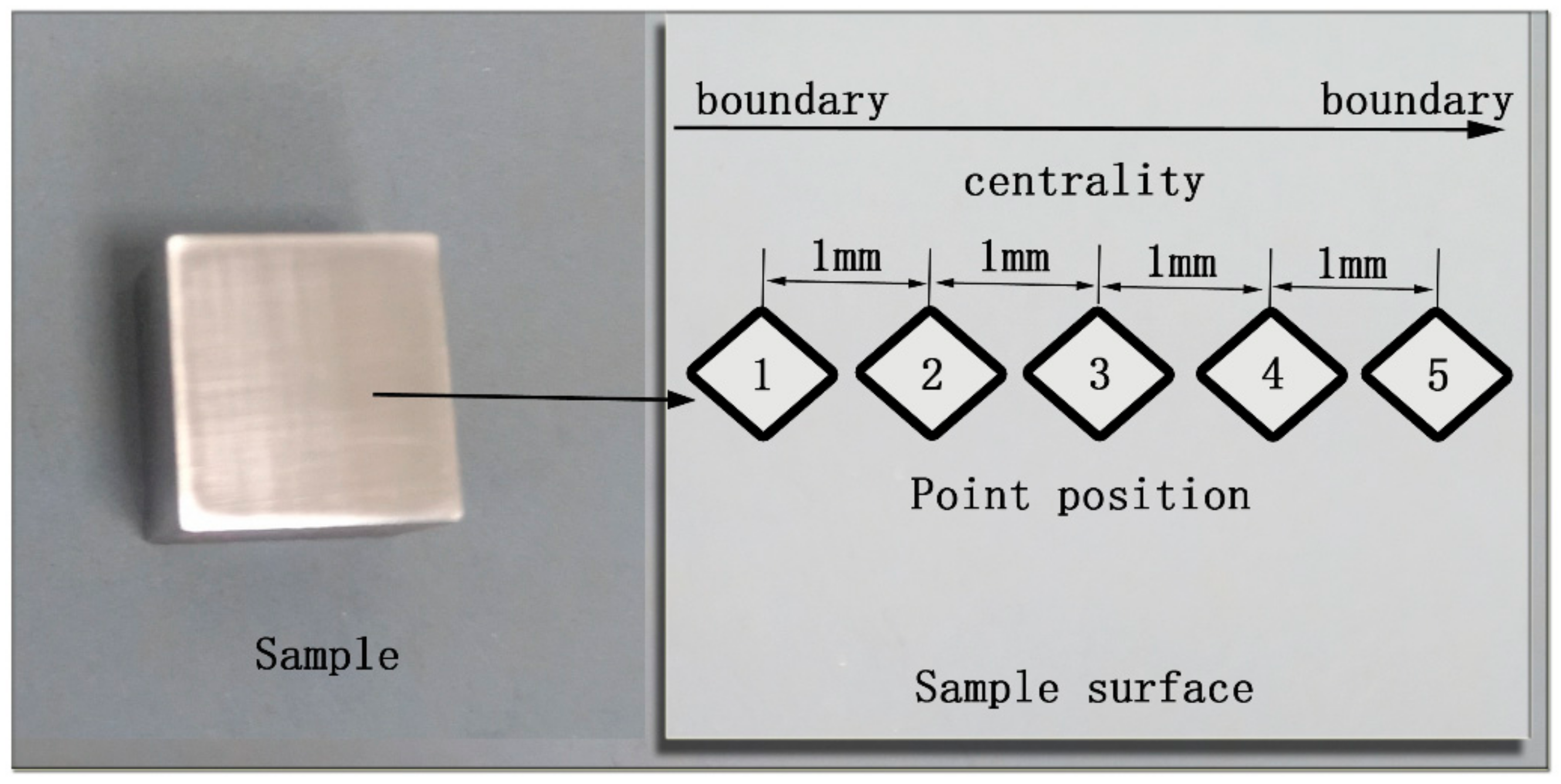
2.4. Mechanical Properties

In this experiment, the microhardness of several samples was tested on a Vickers hardness tester (DHV-1000, Shanghai Shangcai Testing Machine Co., Ltd., Shanghai, China) with a load of 0.98 N and a dwell time of 15 s. The measurement was performed every 1 mm in the vertical direction of the cross section.
According to the GB/T228.1-2010 standard methodology, the tensile properties of the specimens were tested on an E43.504 electronic universal testing machine (MTS Systems Corp., Eden Prairie, MN, USA). The tensile strength test was carried out at room temperature at a rate of 0.5 mm/min.

3. Results and Discussion

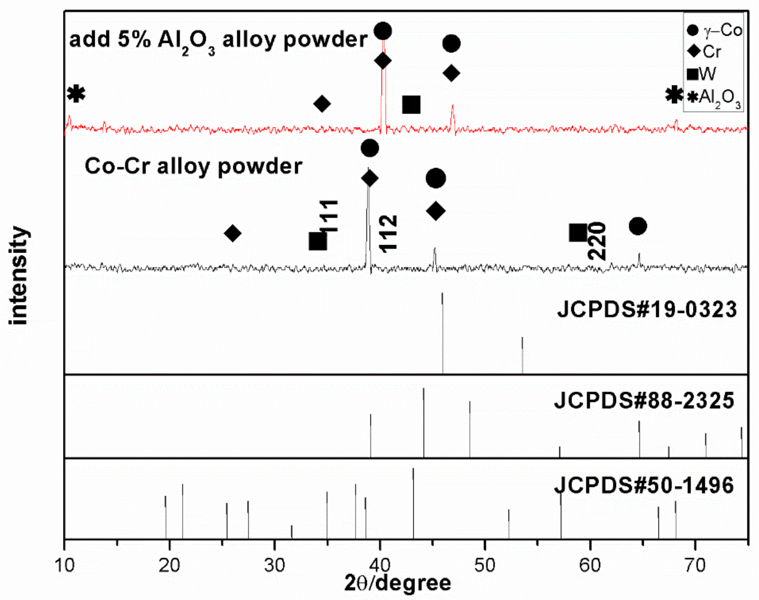
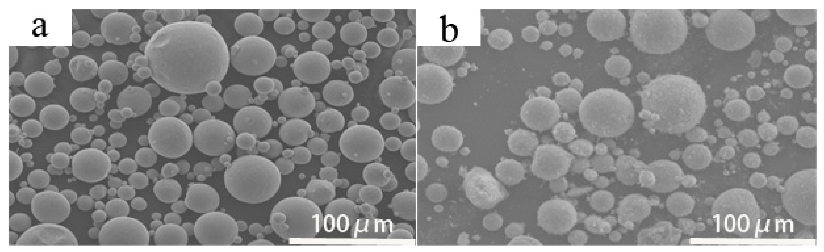
3.1. Alloy Powder Microstructure and Phase Analysis

The analysis of XRD peaks from the CoCr alloy powder showed that the main peak appeared at 38–39° and that the main phase was the face-centered cubic (fcc) γ-Co phase (Figure 1). The standard cell parameter for the fcc γ-Co phase is a = 0.35447 ± 0.0002 (ICDD card #15-806), and the surface indices for the γ (111), γ (112), and γ (220) matched. After adding Al2O3, the main peak of the composite powder appeared at 40–42°.
The XRD data were further analyzed, and it was observed that the main phase did not change substantially after Al2O3 addition, but the Al2O3 phase was identified. The main peak in the γ-Co diffraction spectrum shifted upon the addition of Al2O3, which, according to Bragg’s Law, is attributed to structural changes in the unit cell that cause a change in the diffraction peak positions. This shows that the interplanar spacing and lattice constant decreased, which would affect the deformation performance of the powder.
The particle morphology of the powder remained almost spherical without Al2O3 addition, while smaller particles appeared with Al2O3 addition than those that were present when Al2O3 was not added (Figure 2). The small particles had an elevated specific surface energy and melting enthalpy, and they melted rapidly under laser action. There was also good filling of the gaps between the large particles such that the bulk density of the powder increased. This reduced the void defects inside the formed parts and improved the mechanical properties and surface quality.
Further analysis of the powder properties showed that the Al2O3 powder had a particle size distribution between 9.2 and 33.5 μm, a flowability of 22.10 s/50 g, and a bulk density > 4.2 g/cm3, which satisfied the general requirements of the laser cladding forming process.

3.2. Microstructural and Phase Analysis of Pure CoCr Alloy Powder for Forming Sample Parts

The sample surface and grain structures after molding were observed by SEM. The crystal structure appeared relatively uniform and compact after molding (Figure 3a). However, there were also visible flaws under 1000× magnification, like the local area uplift phenomenon seen in Figure 3b. The reason for this was that during the forming process, impurities were present in the powder, which rendered the powder being non-uniform or led to the formation of very small masses, resulting in local volumes that lacked sufficient density. The microstructural orientation of the CoCr alloy showed no obvious macro-defects such as pores and cracks on the surface of the sample (Figure 3c). This showed that densification of the formed part or piece under this method was high.
At temperatures above 417 °C, the matrix of the Co-based alloy formed the γ-phase (also called austenite) with an fcc structure, and this phase was converted to the γ-phase with its allotrope the ε-phase. As the γ-phase was thermodynamically unstable, the γ → ε phase transformation occurred during laser melting of the selected area. In this study, SLM, such as single-pass scanning of the CoCr alloy powder, resulted in a rapid melting and rapid solidification process.
The Co-based alloy was rapidly melted by the laser heating, did not undergo phase transformation, and remained in the γ-Co phase. This was because the rapid cooling of the substrate to room temperature caused the γ-Co phase to be retained due to the phase change. There are generally two types of carbide structures in CoCr alloys, namely M23C6 and M6C, in which the M6C carbide is rich in Mo, while the M23C6 is rich in Cr [29]. This observation, combined with XRD analysis, indicated that the CoCr alloy produced γ-Co and carbide phases (Formula (1)). The formation of carbides is due to the formation of fine columnar γ-Co grains composed of cellular dendrites in the dendrites of Cr and Mo during rapid solidification, so that carbon segregates between dendrites and grain boundaries, and carbides are precipitated [29].
γ Co γ + + M 23 C 6 + M 6 C
Further analysis of the microstructure of the alloys revealed that the metallographic structure of a single-channel scanned CoCr alloy specimen was composed of austenite and a carbide-like structure (Figure 4a). Its crystal structure was crystalline and columnar, with carbides distributed in the grain boundaries, and agglomeration occurred in the internal structure of the material (Figure 4b). The microstructures consisted of a Co-based solid solution and an agglomerated second phase, which was shown by XRD analysis to be a carbide phase. Based on the energy-dispersive X-ray spectroscopy (EDS) results, it was speculated that one area was a Mo-rich M6C carbide and reticular in shape, while another area was a Cr-rich M23C6-type carbide (mainly Cr23C6 as shown in Figure 4b, points 1 and 2).
The correct amount of carbon can form carbides with the corresponding elements in Co-based alloys. These carbides have long been considered important strengthening phases in Co-based alloys [30,31,32]. The existence of these carbides affects the mechanical properties, wear resistance, corrosion resistance, and biocompatibility of the associated materials [29,33].

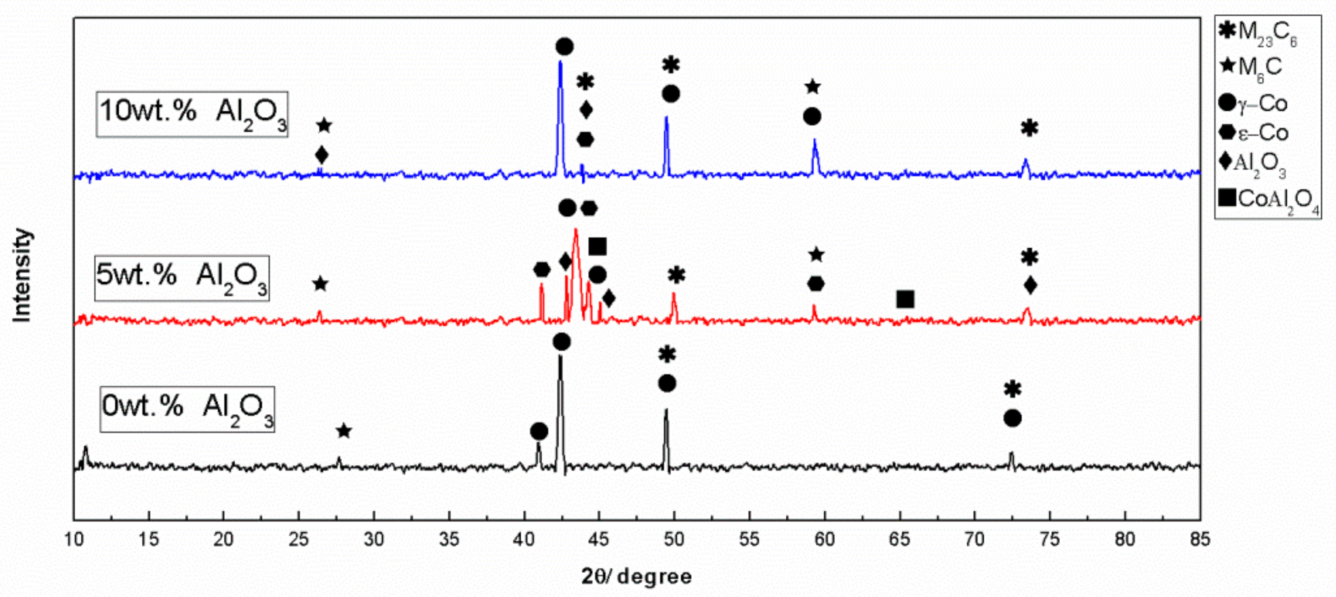
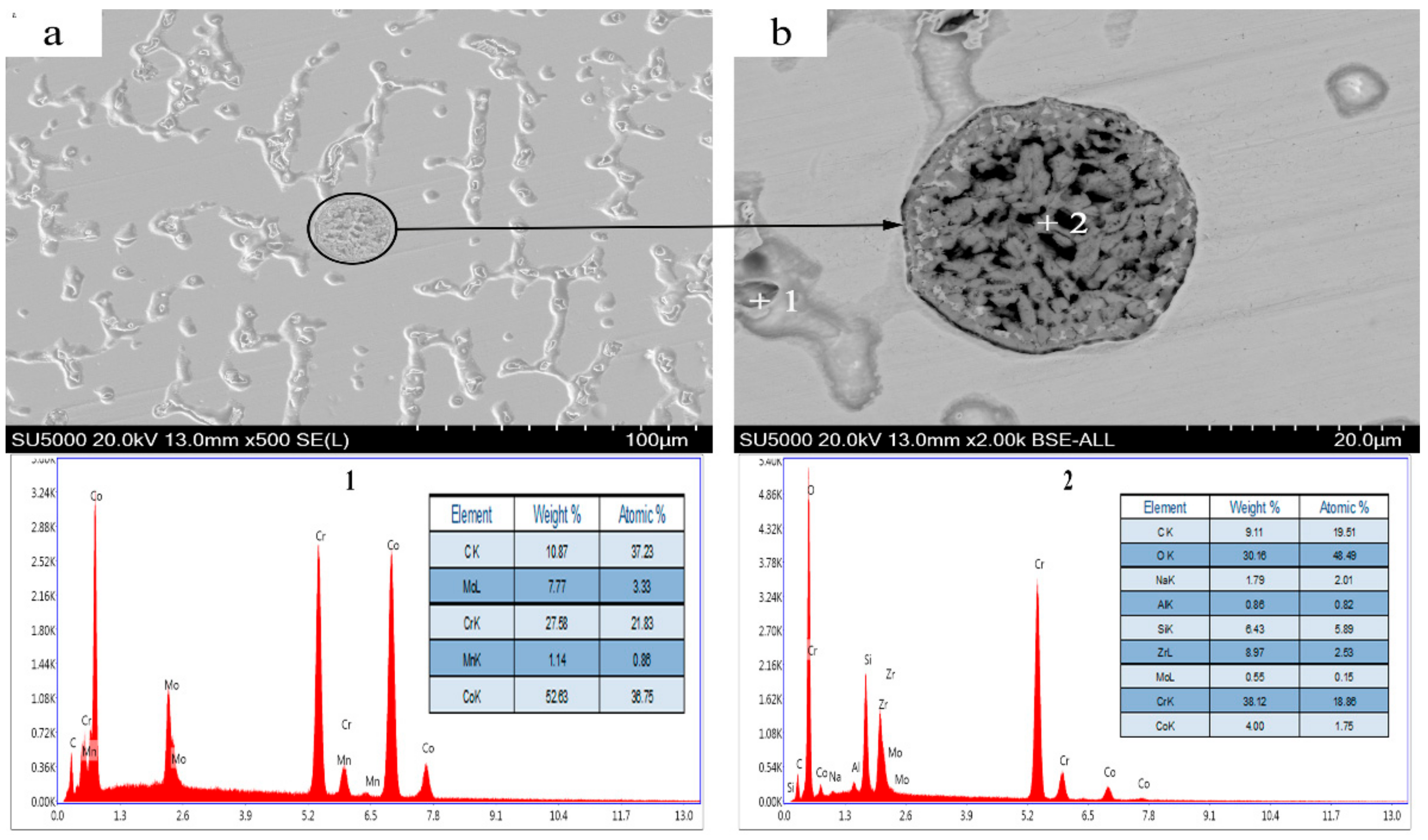
3.3. Microstructural and Phase Analysis of Alloy Powder Molded Parts After Al2O3 Addition

XRD analysis revealed that the alloy phases that were present after the addition of Al2O3 were γ-CO, ε-Co, M23C6, M6C, Al2O3, and CoAl2O4 (Figure 5). Compared to that of the pure CoCr alloy, the XRD diffraction pattern of the alloy with an Al2O3 content of 5% showed that the main phase peak weakened, its angle shifted to the right, the carbide peaks changed, and the intensity of the M6C peaks increased, indicating that the amount of the M6C phase increased. At this time, ε-Co appeared in contrast to the γ phase that is present without Al2O3, because of the low thermal conductivity of Al2O3 (10.022 W∙m−1∙K−1 at 1200 °C). During the melting-cooling process, the large amounts of fine Al2O3 particles contained in the crystals and crystal fronts (Figure 6) hindered heat transfer not only from the liquid but also from the solid part of the solidifying material, eventually causing a portion of the γ-Co to convert to ε-Co particles at a decreased cooling rate. The main phase of the reaction is shown in Formula (2):
γ Co γ + ε + M 23 C 6 + M 6 C + Al 2 O 3 + CoAl 2 O 4
Comparing Figure 3d and Figure 7, it can clearly be seen that the alloy structure was still columnar and crystalline after Al2O3 addition, but the columnar grains decreased in size and were even smaller than those in the alloy without Al2O3 addition. Additionally, a large amount of carbide disappeared, and Al2O3 agglomeration areas appeared.
When the Al2O3 content was 5%, the grain boundaries were the most visible in the microstructure, and the columnar grains were small in size and similar in appearance to equiaxed grains (Figure 7a–d). Carbide accumulation areas were almost undetectable, and the microstructure and properties of the parts characterized herein were therefore judged to be the best when the Al2O3 content was 5%. Further analysis was carried out on characterized parts and grain boundaries were observed under magnification, which revealed that local areas had an appearance similar to that of a cellular structure and the columnar grains disappeared (Figure 8a, point 1). In the deep regions of the material with Al2O3 particles (Figure 8a, point 3), it was observed from the backscatter plot in Figure 8b that the black areas were Al2O3 precipitates, whereas the bright white areas were composed of carbides. According to the EDS results, in Figure 8a, point 1 was Mo-rich M6C and point 2 was Cr-rich M23C6. When compared with that of a non-Al2O3 alloy, the carbon content in these two points was significantly reduced, the carbide grain size was small, and the position where it occurred changed; it also did not take the form of a mesh or sheet but became granular instead. The conclusion here was that the addition of Al2O3 to the alloy reduced the final carbide content of the molded part. This is because in CoCr alloys, γ-Co grains themselves have a substantial amount of stacking faults, which creates nucleation centers for carbides in CoCr alloys [34]. In this study, adding Al2O3 caused the final morphology of the γ-Co grains to change during the nucleation process. Due to the fine structure, it was inferred that the stacking faults in the γ-Co grains were reduced along with the carbide nucleation, which changed the time and amount of carbides produced.
In Figure 8a, point 3 and area A were examined using EDS, and Al and O were detected. Considering these results in combination with those from XRD analysis (Figure 5), we concluded that the amount of carbides was further reduced. Al was a solid solution in the Co-based solid solution, the peak from the main phase slowly weakened, its angle shifted to the right, the carbide peaks changed, and the intensity of the peaks from the M6C phase increased, indicating that the amount of M6C phase increased. M6C carbides have been reported to have good thermal stability, and M23C6 carbides were shown to convert to M6C at a solution temperature of 1165 °C [35]. During the laser cladding process, there was a heat-effected zone that led to the conversion of the M23C6 carbide to the M6C type. Furthermore, the addition of Al2O3 reduced the nucleation sites for the M23C6 carbides, creating the appropriate conditions for the conversion of M23C6 to M6C.
When the Al2O3 content was 7.5%, the number of columnar crystals increased (Figure 7c), but the arrangement was chaotic, and the overall structural properties were not as good as those with 5% Al2O3. When the Al2O3 content was further increased to 10%, the microstructure remained columnar (Figure 9a). Per the XRD analysis results (Figure 5), we see that the main peak increased in intensity and decreased in width when additional carbides were present. There were still deep areas similar to those found in the previous alloy (Figure 9b), where carbides were present in a manner similar to those without Al2O3 (Figure 9, point 1). The elemental distributions at points 1 and 2 were determined by EDS scanning that showed that in deep regions, the elements were different from the previous alloy (Figure 8) because the Al disappeared and the C content increased. The C content also significantly increased at other points. The analysis of the elemental distributions at points 1 and 2 in Figure 9 revealed that the elements at these points were essentially the same as those in the pure CoCr alloy.
The existence of Al2O3 particles clearly changed the microstructure of the CoCr alloy. The reason for these results is that Al2O3 has a small particle size, large surface energy, and high melting point. When Al2O3 particles were added in small amounts, they were uniformly distributed in the liquid metal (Figure 6), which not only increased the degree of super-cooling but also promoted spontaneous nucleation at the front of the columnar solidification and hindered dendrite growth. During rapid solidification and crystallization, a portion of Al2O3 particles was in the solid solution, and nucleation occurred spontaneously at the solid-liquid interface (Figure 10). Because of the large surface effects of Al2O3 particles, they accessed atoms from the surrounding metal liquid and grew after nucleation. As observed in Figure 8b, part of the Al2O3 particle agglomeration resided in the columnar stem, and part of the columnar front obstructed the crystal growth. The reason for the observed agglomeration was that Al2O3 was larger in area than the surface area and was absorbed very easily onto the material surfaces.
When the Al2O3 content was increased to 10% and the Al2O3 particles increased, the solid solution rapidly contacted additional Al2O3 particles, which grew as nuclei. The contacted particles were not in the form of solid nuclei but were solid solution particles. These large and elongated particles had different orientations in the columnar crystal structure and were interlocked with each other. Since it was very easy to induce cracks in these interlocking regions during processing, the mechanical properties were significantly reduced. In several samples with 10% Al2O3 content, the comprehensive analysis of the microstructural properties was the worst among the samples studied herein. In summary, the microstructure and properties of the alloy were the best among the samples studied herein when 5% Al2O3 was added.

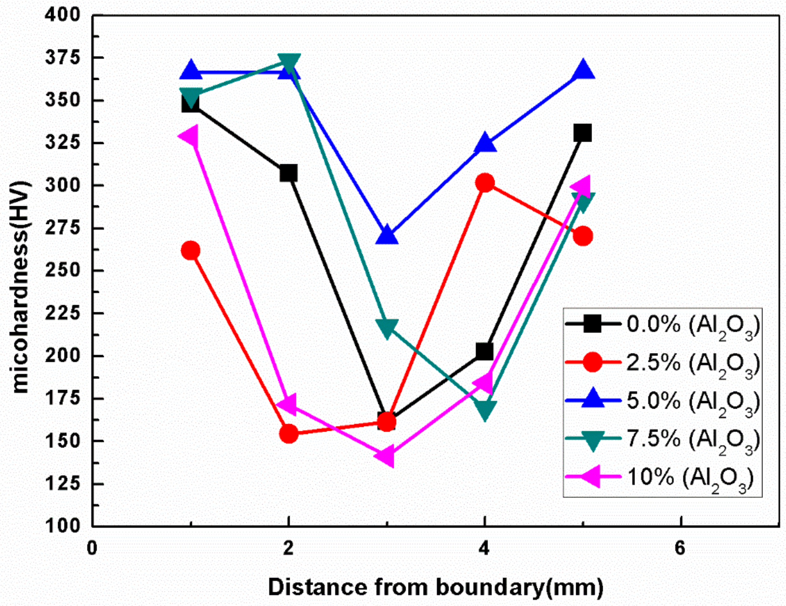
3.4. Mechanical Properties

Figure 11 is a schematic diagram of the microhardness measurement of the sample, and Figure 12 is the microhardness curve of the alloy components of the selected laser. It can be seen that the microhardness of the boundary is significantly higher than the central region, and the hardness tends to decrease from the boundary to the center. This is mainly because the boundary part is in direct contact with the powder during the solidification process, the temperature gradient is large, the heat is transmitted to the outside through the powder, the cooling rate is high, and fine-grain strengthening is performed so that the grain size of this part is small. As the transition to the central region was gradually reduced, the temperature gradient was gradually reduced, the crystal grains were sufficiently grown, and the microhardness was correspondingly reduced.
As shown in Figure 12, among the several components, the microhardness of the 5% oxidized Al2O3 alloy was relatively small from the boundary to the center, with an average Vickers hardness of 338.775 HV, which corresponded to 335 HV of the CoCr alloy tooth standard and was therefore slightly above the standard specification (Figure 12).
Combined with the previous analysis, the microstructure of the alloy under this component was better (Figure 7), the crystallites were finer, and the microhardness was consistent with the observed microstructure. Therefore, it can be judged that the microhardness of the alloy was the best at this time.
It can be seen from Figure 13 that when the content of Al2O3 was 5%, the microstructure of CoCr alloy was dense and there was no obvious stomatal defect, but in the case of other additions, the microstructure of cobalt-chromium alloy will be affected by Al2O3 powder to produce different defects, which also explains why the mechanical properties of modified cobalt-chromium alloy were the best when the content of Al2O3 was 5%.
The representative stress–strain curves of the CoCr alloy doped with different percentages of Al2O3 show that the tensile properties of CoCr alloy were the best among the samples herein when the content of Al2O3 was 5% and reached a value of 856 MPa, which was markedly higher than the minimum value (665 MPa) recommended in ISO5832-4 and GB17100 (Figure 14). Furthermore, the specimen also exhibited a high elongation-to-failure percentage of 12.79%, while ISO5832-4 specifies that the minimum requirement for elongation is 8%.
Since CoCr alloy is widely used in dental restoration, it has an important role in improving its mechanical properties. Studies have shown that the high yield strength of the alloy prevents permanent deformation of the prosthesis, especially in fixed partial denture stents [36]. In addition, a yield strength of more than 300 MPa is sufficient to resist permanent deformation.
It can be seen from Table 1 that the Al2O3 content of 5% not only satisfies the above requirements, but also has the best mechanical properties and microstructure compared to other groups. The reason for the analysis is as follows: SLM technology can complete local melting and, at the same time, accelerate the solidification due to the presence of Al2O3 particles, minimizing defects and pores (Figure 13), resulting in dense and uniform grains.
It is well known that the grain size is closely related to the nucleation rate, and the presence of Al2O3 particles accelerates the nucleation rate and refines the grains [37]. Not only can grain refinement significantly strengthen the alloy, it also improves the ductility and toughness of the alloy, which is an important reason for the improvement of the mechanical properties of the 5% Al2O3 content alloy. In addition, rapid solidification increases the solid solution limit of solute elements, reduces dendrite segregation, and affects performance improvement in two ways.
The tensile strength of alloy specimens with 5% Al2O3 was tested, and the fracture surfaces examined at different magnifications showed that the former interface between the powder particles could not be distinguished, indicating that the alloy achieved full metallurgical bonding (Figure 15a). In addition, a mixture of smooth and rough zones was observable, with the presence of a high portion of rough regions that are indicative of predominantly ductile fracture [38]. The fracture surfaces of the alloy had parabolic tearing edges and dimple-like structures (Figure 14b and Figure 15a), suggesting ductile quasi-cleavage fractures [27]. It appeared that the alloy ductility was improved when the local plastic zone appeared during fracture.
Yamanaka [24] studied high-entropy alloys and found that the carbides (M23C6 and M6C) were much harder than the surrounding γ-phase substrates and tended to strengthen the alloy. In this study, when the Al2O3 content was 5%, the alloy microstructure and carbide morphology changed on one hand, and the carbide morphology changed on the other, which enhanced the microhardness and elongation of the alloy. In addition, the microstructures were mainly fine columnar crystals that improved the ultimate tensile strength. The carbide content increased with increasing content, but the grain size was coarse, which resulted in deterioration in the mechanical properties of the CoCr alloy.
We found that after adding 5% Al2O3, the microstructure of the alloy became fine and enabled grain strengthening. It is precisely due to this effect that the mechanical properties of the alloy improved remarkably. Additionally, the γ-Co grain boundary might have provided a rapid diffusion path for Cr and Mo. Due to enhanced diffusion, the carbide eutectic structure was very hard, and the carbides dispersed in the eutectic phase existed at the interface, which improved the strength and hardness of the alloy. Therefore, the introduction of 5% Al2O3 was an effective way of improving the mechanical properties of the CoCr alloy. Thus, this study provided insight for improving the wear properties and biocompatibility of CoCr alloys.

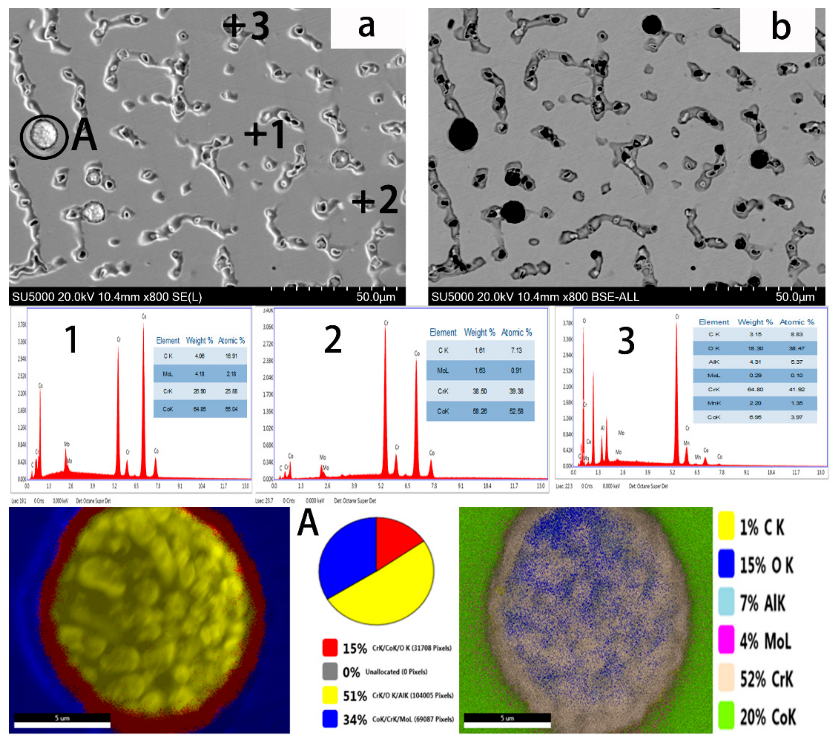
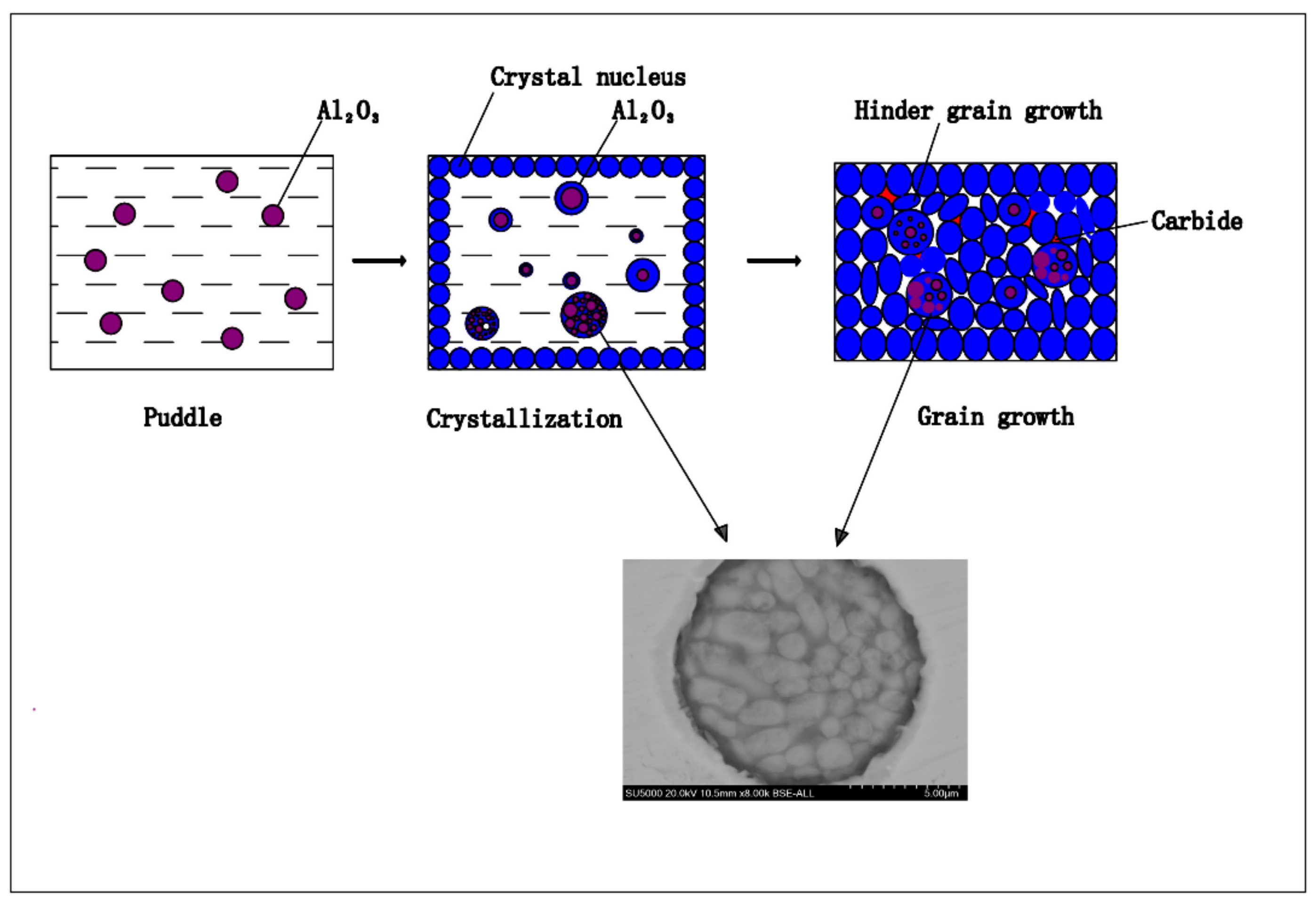
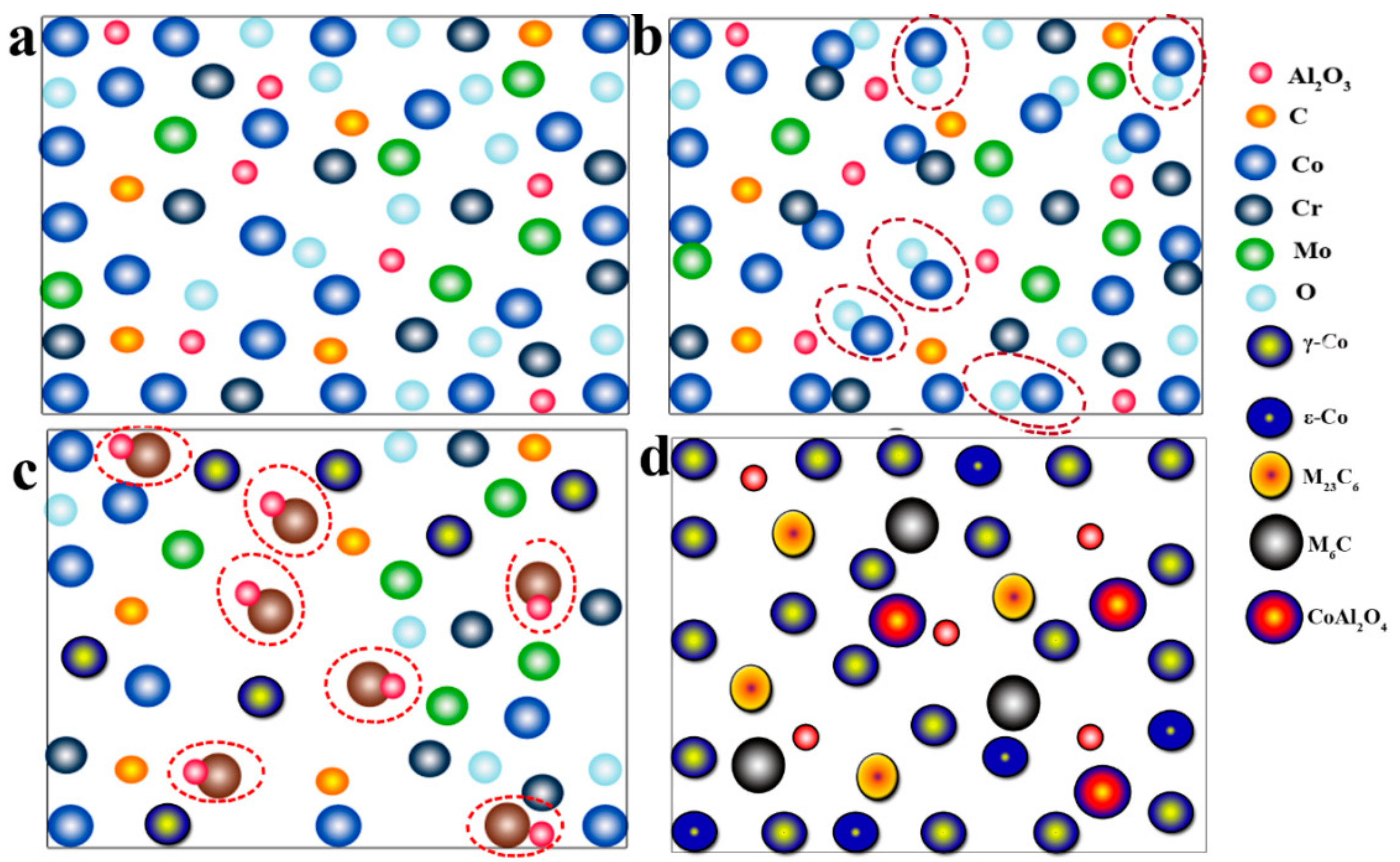
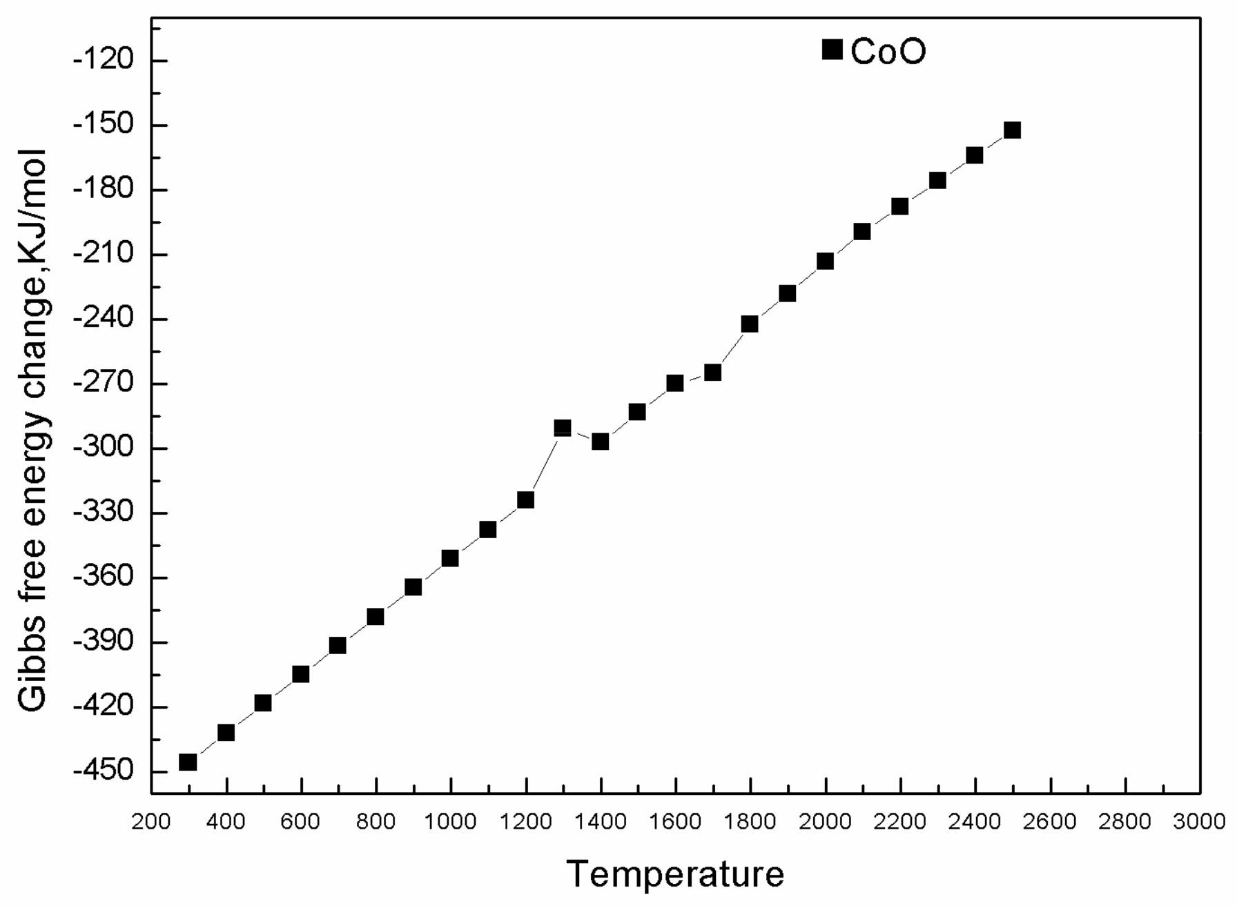
3.5. Formation Mechanism of the CoAl2O4 Phase

The formation of an alloy from mixed powders after the addition of Al2O3 showed that the mixture was melted (Figure 16a). As the temperature increased, Co and O reacted to form CoO while the diffusion of Cr and Mo began to occur (Figure 16b). Then, the previously formed CoO and Al2O3 reacted to form CoAl2O4 (Figure 15d and Figure 16c).
The appearance of the CoAl2O4 phase might also have been because Al2O3 particle bonds were not saturated, and new nucleation centers in the molten pool were growing. As the nucleation centers grew, the O and Co in the alloying material were adsorbed and combined during the growth process.
The following reactions were inferred to occur during laser cladding:
Co + O CoO
CoO + Al 2 O 3 CoAl 2 O 4
We calculated the Gibbs free energy of Reaction (3) at 298~2000 K by referring to the Thermochemical Data of Pure Substances [39]. The results show that Reaction (3) can be carried out spontaneously, which indicates that the reaction proceeds readily (Figure 17). Due to the strong interactions between Co and Al2O3, a cobalt acicular spinel compound was easily produced and was difficult to reduce [40], meaning that Reaction (4) occurred readily as well and that the resulting CoAl2O4 enabled the final morphology to assume the fine microstructure observed in the present study.

4. Conclusions

This work mainly studied the powder and molding properties of CoCr alloy upon the addition of different proportions of Al2O3. The results were compared with those of a pure CoCr alloy, and the following conclusions were drawn:
(1)
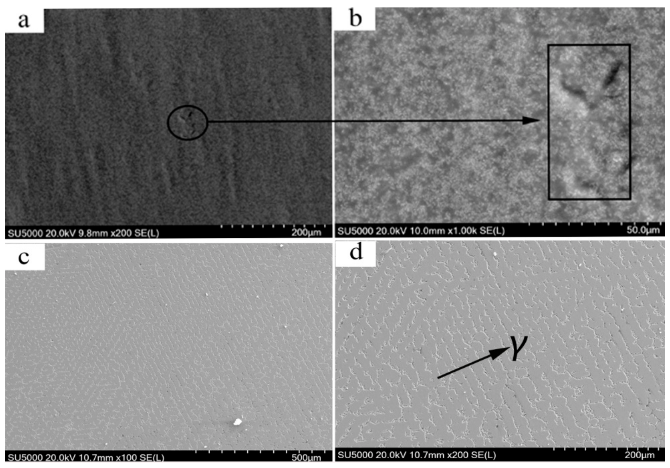
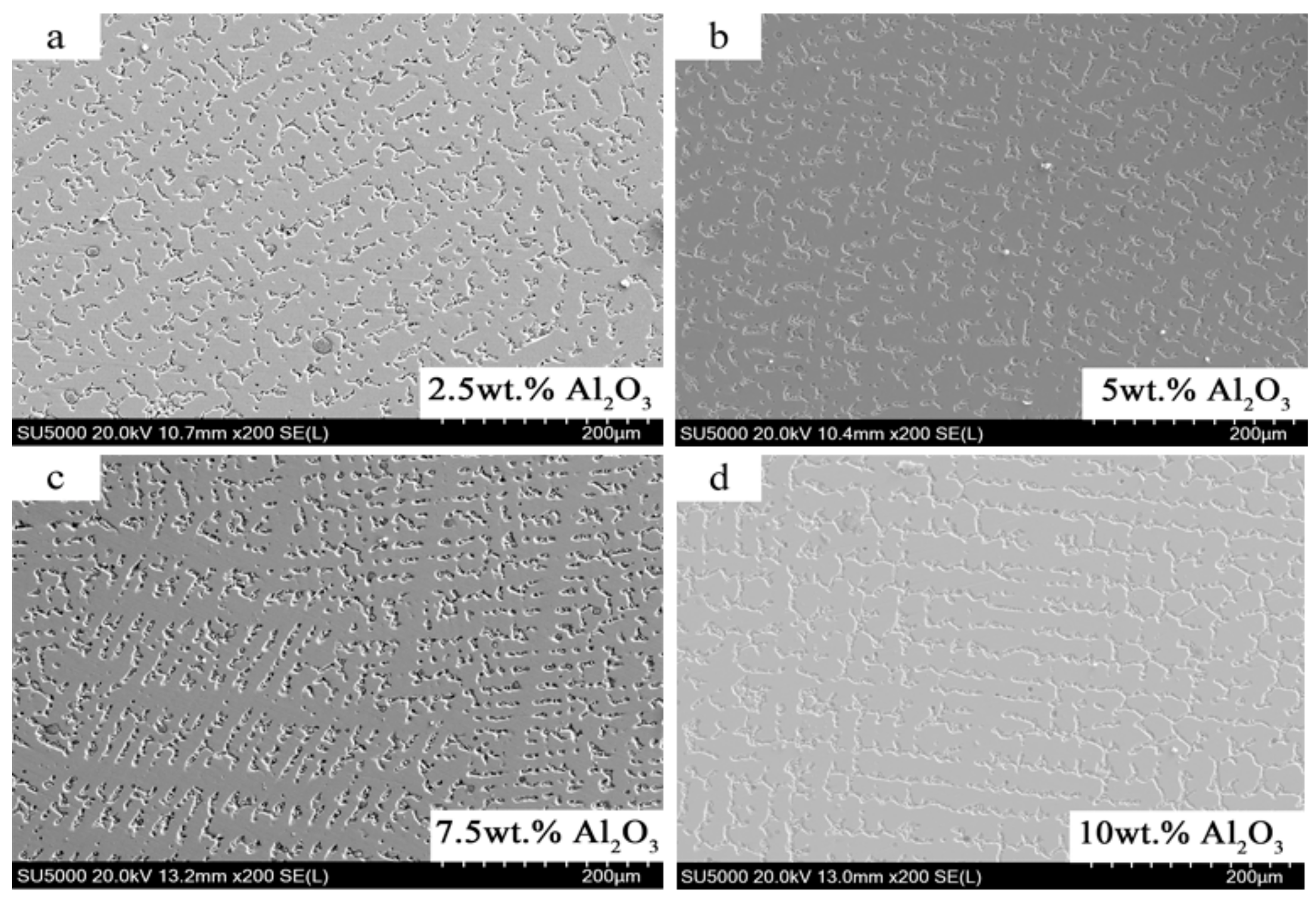
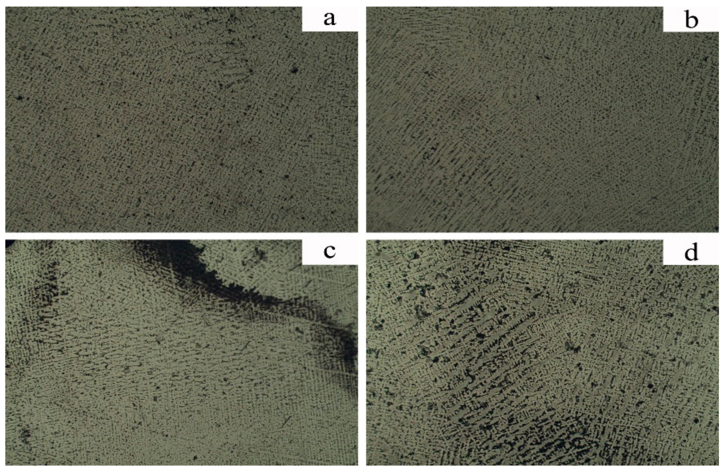
Among all the ratios, the microstructure and mechanical properties of the alloy were the best when the content of Al2O3 was 5%. At that time, the deep region of the Al2O3 particles appeared in the microstructure of the alloy, which hindered the growth of dendrites. These results showed that the columnar grain size of the alloy with Al2O3 was obviously smaller than that of the alloy without adding Al2O3.
(2)
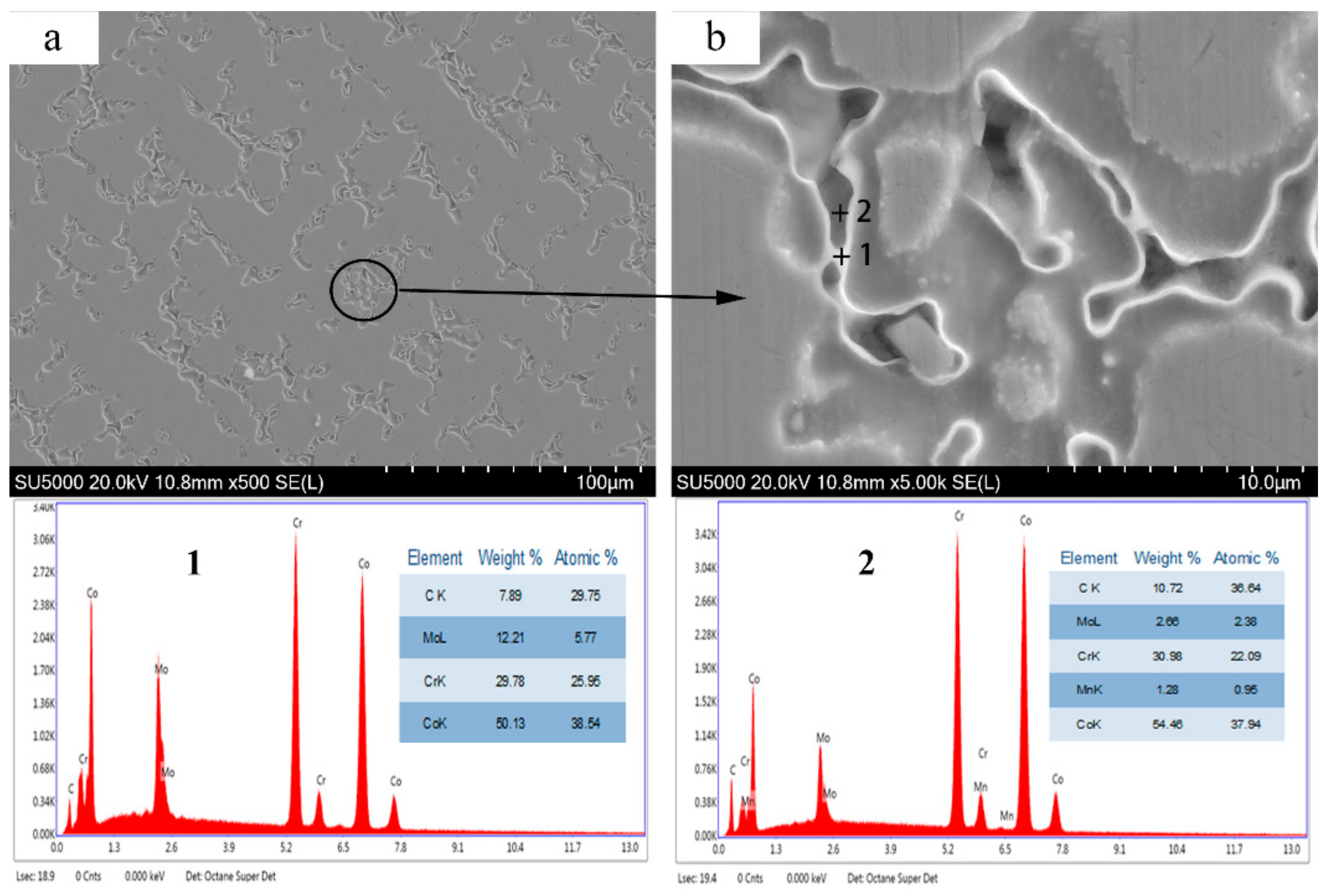
With the addition of Al2O3, the accumulation area of carbides in the microstructure of the alloy almost disappeared, and the M6C phase increased, which indicated a change in the microstructure and morphology of the CoCr alloy.
(3)
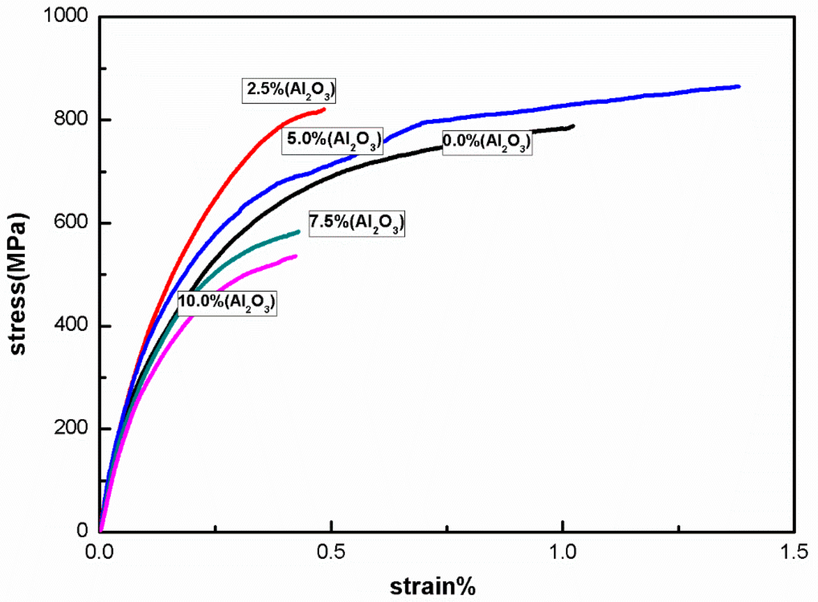
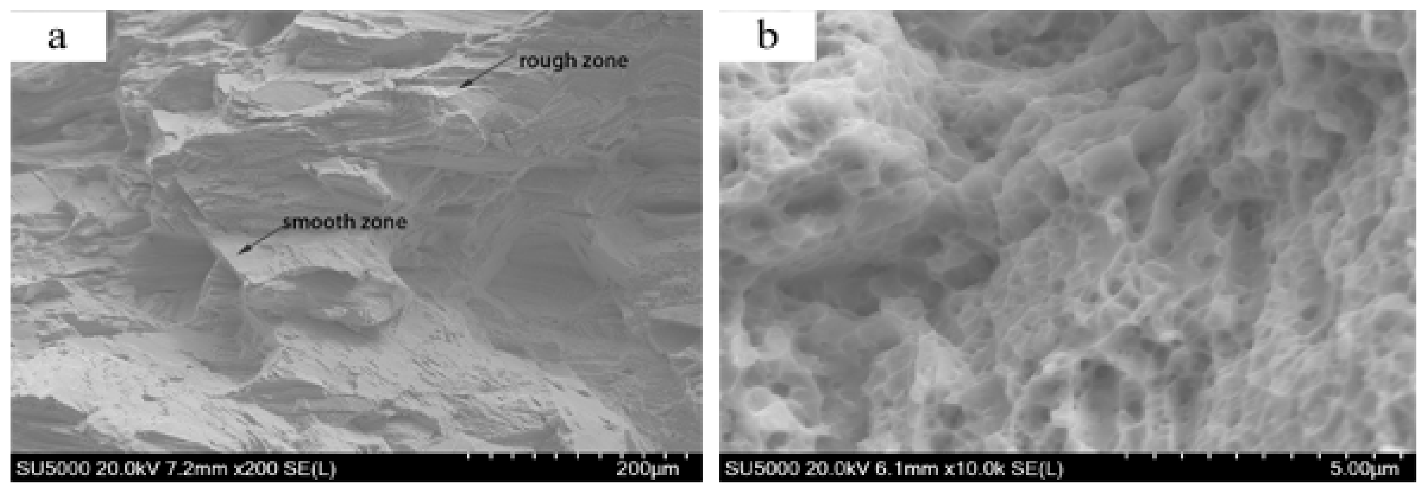
The average Vickers hardness of the alloy mixed with 5% Al2O3 was 338.775 HV, and the tensile strength was 856 MPa. From the fracture morphology analysis of the alloy, it was concluded that the local plastic zone appears during the fracture of the alloy. This suggests that the mechanical properties of the alloy were improved.

Author Contributions

Conceptualization, Q.H. and J.W.; methodology, P.B.; validation, Q.H., J.W. and P.W.; formal analysis, Q.H.; investigation, Q.H.; resources, J.W. and P.W.; data curation, Q.H.; writing—original draft preparation, Q.H.; writing—review and editing, J.W.; visualization, Q.H.; supervision, P.B.; project administration, J.W.; funding acquisition, J.W., P.B.

Funding

This research work was funded by Primary Research and Development Plan of Shanxi Province (Grant No. 201603D121020-1).

Acknowledgments

This research work was supported by Primary Research and Development Plan of Shanxi Province (Grant No. 201603D121020-1). The authors are grateful for these grants.

Conflicts of Interest

The authors declare no conflict of interest.

References

  1. Davis, J.R. Handbook of Materials for Medical Devices. Available online: https://www.researchgate.net/publication/313151336_Handbook_of_Materials_for_Medical_Devices (accessed on 1 January 2018).
  2. Li, J.; Chen, C.; Liao, J.; Liu, L.; Ye, X.; Lin, S.; Ye, J. Bond strengths of porcelain to cobalt-chromium alloys made by casting, milling, and selective laser melting. J. Prosthet. Dent. 2017, 118, 69–75. [Google Scholar] [CrossRef] [PubMed]
  3. Svanborg, P. A 5-Year Retrospective Study of Cobalt-Chromium–Based Fixed Dental Prostheses. Int. J. Prosthodont. 2013, 26, 343–349. [Google Scholar] [CrossRef] [PubMed]
  4. Al Jabbari, Y.S.; Koutsoukis, T.; Barmpagadaki, X.; Zinelis, S. Metallurgical and interfacial characterization of PFM Co-Cr dental alloys fabricated via casting, milling or selective laser melting. Dent. Mater. 2014, 30, e79–e88. [Google Scholar] [CrossRef] [PubMed]
  5. Malayoglu, U.; Neville, A. Mo and W as alloying elements in Co-based alloys—Their effects on erosion–Corrosion resistance. Wear 2005, 259, 219–229. [Google Scholar] [CrossRef]
  6. Qin, L.; Sun, H.; Hafezi, M.; Zhang, Y. Polydopamine-Assisted Immobilization of Chitosan Brushes on a Textured CoCrMo Alloy to Improve its Tribology and Biocompatibility. Materials 2019, 12, 3014. [Google Scholar] [CrossRef] [PubMed]
  7. Quante, K.; Ludwig, K.; Kern, M. Marginal and internal fit of metal-ceramic crowns fabricated with a new laser melting technology. Dent. Mater. 2008, 24, 1311–1315. [Google Scholar] [CrossRef] [PubMed]
  8. Traini, T.; Mangano, C.; Sammons, R.L.; Mangano, F.; Macchi, A.; Piattelli, A. Direct laser metal sintering as a new approach to fabrication of an isoelastic functionally graded material for manufacture of porous titanium dental implants. Dent. Mater. 2008, 24, 1525–1533. [Google Scholar] [CrossRef]
  9. Alt, V.; Hannig, M.; Wostmann, B.; Balkenhol, M. Fracture strength of temporary fixed partial dentures: CAD/CAM versus directly fabricated restorations. Dent. Mater. 2011, 27, 339–347. [Google Scholar] [CrossRef] [PubMed]
  10. Hedberg, Y.S.; Qian, B.; Shen, Z.; Virtanen, S.; Wallinder, I.O. In vitro biocompatibility of CoCrMo dental alloys fabricated by selective laser melting. Dent. Mater. 2014, 30, 525–534. [Google Scholar] [CrossRef]
  11. Qian, B.; Saeidi, K.; Kvetkova, L.; Lofaj, F.; Xiao, C.; Shen, Z. Defects-tolerant Co-Cr-Mo dental alloys prepared by selective laser melting. Dent. Mater. 2015, 31, 1435–1444. [Google Scholar] [CrossRef]
  12. Cassar, J.; Mallia, B.; Mazzonello, A.; Karl, A.; Buhagiar, J. Improved Tribocorrosion Resistance of a CoCrMo Implant Material by Carburising. Lubricants 2018, 6, 76. [Google Scholar] [CrossRef]
  13. Poolphol, N.; Sakkaew, T.; Kachin, K.; Jantaratana, P.; Vittayakorn, W. Physical, mechanical and magnetic properties of cobalt-chromium alloys prepared by conventional processing. Mater. Today Proc. 2017, 4, 6358–6364. [Google Scholar] [CrossRef]
  14. Li, K.C.; Prior, D.J.; Waddell, J.N.; Swain, M.V. Comparison of the microstructure and phase stability of as-cast, CAD/CAM and powder metallurgy manufactured Co-Cr dental alloys. Dent. Mater. 2015, 31, e306–e315. [Google Scholar] [CrossRef] [PubMed]
  15. Yager, S.; Ma, J.; Ozcan, H.; Kilinc, H.I.; Elwany, A.H.; Karaman, I. Mechanical properties and microstructure of removable partial denture clasps manufactured using selective laser melting. Addit. Manuf. 2015, 8, 117–123. [Google Scholar] [CrossRef]
  16. Bezzon, O.L.; De Mattos, M.D.G.; Ribeiro, R.F.; De Almeida Rollo, J.M. Effect of beryllium on the castability and resistance of ceramometal bonds in nickel-chromium alloys. J. Prosthet. Dent. 1998, 80, 570–574. [Google Scholar] [CrossRef]
  17. Jang, S.-H.; Min, B.; Hong, M.-H.; Kwon, T.-Y. Effect of Different Post-Sintering Temperatures on the Microstructures and Mechanical Properties of a Pre-Sintered Co–Cr Alloy. Metals 2018, 8, 1036. [Google Scholar] [CrossRef]
  18. Wang, J.H.; Ren, J.; Liu, W.; Wu, X.Y.; Gao, M.X.; Bai, P.K. Effect of Selective Laser Melting Process Parameters on Microstructure and Properties of Co-Cr Alloy. Materials 2018, 11, 1546. [Google Scholar] [CrossRef]
  19. Ayu, H.M.; Izman, S.; Daud, R.; Krishnamurithy, G.; Shah, A.; Tomadi, S.H.; Salwani, M.S. Surface Modification on CoCrMo Alloy to Improve the Adhesion Strength of Hydroxyapatite Coating. Procedia Eng. 2017, 184, 399–408. [Google Scholar] [CrossRef] [Green Version]
  20. Asri, R.I.M.; Harun, W.S.W.; Samykano, M.; Lah, N.A.C.; Ghani, S.A.C.; Tarlochan, F.; Raza, M.R. Corrosion and surface modification on biocompatible metals: A review. Mater. Sci. Eng. C Mater. Biol. Appl. 2017, 77, 1261–1274. [Google Scholar] [CrossRef] [Green Version]
  21. Mori, M.; Sato, N.; Yamanaka, K.; Yoshida, K.; Kuramoto, K.; Chiba, A. Development of microstructure and mechanical properties during annealing of a cold-swaged Co-Cr-Mo alloy rod. J. Mech. Behav. Biomed. Mater. 2016, 64, 187–198. [Google Scholar] [CrossRef]
  22. Mengucci, P.; Barucca, G.; Gatto, A.; Bassoli, E.; Denti, L.; Fiori, F.; Girardin, E.; Bastianoni, P.; Rutkowski, B.; Czyrska-Filemonowicz, A. Effects of thermal treatments on microstructure and mechanical properties of a Co-Cr-Mo-W biomedical alloy produced by laser sintering. J. Mech. Behav. Biomed. Mater. 2016, 60, 106–117. [Google Scholar] [CrossRef] [PubMed]
  23. Hernandez-Rodriguez, M.A.L.; Mercado-Solis, R.D.; Presbitero, G.; Lozano, D.E.; Martinez-Cazares, G.M.; Bedolla-Gil, Y. Influence of Boron Additions and Heat Treatments on the Fatigue Resistance of CoCrMo Alloys. Materials 2019, 12, 1076. [Google Scholar] [CrossRef] [PubMed]
  24. Yamanaka, K.; Mori, M.; Chiba, A. Nanoarchitectured Co-Cr-Mo orthopedic implant alloys: Nitrogen-enhanced nanostructural evolution and its effect on phase stability. Acta Biomater. 2013, 9, 6259–6267. [Google Scholar] [CrossRef] [PubMed]
  25. Kotoban, D.; Nazarov, A.; Shishkovsky, I. Comparative Study of Selective Laser Melting and Direct Laser Metal Deposition of Ni 3 Al Intermetallic Alloy. Procedia IUTAM 2017, 23, 138–146. [Google Scholar] [CrossRef]
  26. Cai, J.; Nordin, G.P.; Kim, S.; Jiang, J. Surface properties and corrosion behavior of Co-Cr alloy fabricated with selective laser melting technique. Cell Biochem. Biophys. 2013, 67, 983–990. [Google Scholar]
  27. Takaichi, A.; Nakamoto, T.; Joko, N.; Nomura, N.; Tsutsumi, Y.; Migita, S.; Doi, H.; Kurosu, S.; Chiba, A.; Wakabayashi, N.; et al. Microstructures and mechanical properties of Co-29Cr-6Mo alloy fabricated by selective laser melting process for dental applications. J. Mech. Behav. Biomed. Mater. 2013, 21, 67–76. [Google Scholar] [CrossRef]
  28. Hagihara, K.; Nakano, T.; Sasaki, K. Anomalous strengthening behavior of Co–Cr–Mo alloy single crystals for biomedical applications. Scr. Mater. 2016, 123, 149–153. [Google Scholar] [CrossRef]
  29. Bettini, E.; Eriksson, T.; Boström, M.; Leygraf, C.; Pan, J. Influence of metal carbides on dissolution behavior of biomedical CoCrMo alloy: SEM, TEM and AFM studies. Electrochim. Acta 2011, 56, 9413–9419. [Google Scholar] [CrossRef]
  30. Huang, K.; Marthinsen, K.; Zhao, Q.; Logé, R.E. The double-edge effect of second-phase particles on the recrystallization behaviour and associated mechanical properties of metallic materials. Prog. Mater. Sci. 2018, 92, 284–359. [Google Scholar] [CrossRef]
  31. Liao, Y.; Pourzal, R.; Stemmer, P.; Wimmer, M.A.; Jacobs, J.J.; Fischer, A.; Marks, L.D. New insights into hard phases of CoCrMo metal-on-metal hip replacements. J. Mech. Behav. Biomed. Mater. 2012, 12, 39–49. [Google Scholar] [CrossRef] [Green Version]
  32. Chiba, A.; Kumagai, K.; Nomura, N.; Miyakawa, S. Pin-on-disk wear behavior in a like-on-like configuration in a biological environment of high carbon cast and low carbon forged Co–29Cr–6Mo alloys. Acta Mater. 2007, 55, 1309–1318. [Google Scholar] [CrossRef]
  33. Song, C.; Zhang, M.; Yang, Y.; Wang, D.; Jia-kuo, Y. Morphology and properties of CoCrMo parts fabricated by selective laser melting. Mater. Sci. Eng. A 2018, 713, 206–213. [Google Scholar] [CrossRef]
  34. Leinfelder, K.F. Porcelain esthetics for the 21st century. J. Am. Dent. Assoc. 2000, 131, 47S–51S. [Google Scholar] [CrossRef]
  35. Rao, C. Effect of heat treatment on corrosion behavior of weld deposited Co-Cr-Mo alloy. ARPN J. Eng. Appl. Sci. 2016, 11, 12188–12191. [Google Scholar]
  36. Zhou, Y.; Li, N.; Yan, J.; Zeng, Q. Comparative analysis of the microstructures and mechanical properties of Co-Cr dental alloys fabricated by different methods. J. Prosthet. Dent. 2018, 120, 617–623. [Google Scholar] [CrossRef]
  37. Cantor, B. Fundamentals of Rapid Solidification. In Science and Technology of the Undercooled Melt; Springer: Dordrecht, The Netherlands, 1986. [Google Scholar]
  38. Xian, X.; Zhong, Z.; Zhang, B.; Song, K.; Chen, C.; Wang, S.; Cheng, J.; Wu, Y. A high-entropy V 35 Ti 35 Fe 15 Cr 10 Zr 5 alloy with excellent high-temperature strength. Mater. Des. 2017, 121, 229–236. [Google Scholar] [CrossRef]
  39. Barin, I.; Platzki, G. Thermochemical Data of Pure Substances; VCH: Weinheim, NY, USA, 1995. [Google Scholar]
  40. Tavasoli, A.; Karimi, S.; Taghavi, S.; Zolfaghari, Z.; Amirfirouzkouhi, H. Comparing the deactivation behaviour of Co/CNT and Co/γ-Al2O3 nano catalysts in Fischer-Tropsch synthesis. J. Nat. Gas. Chem. 2012, 21, 605–613. [Google Scholar] [CrossRef]
Figure 1. X-ray powder diffraction (XRD) patterns of original and modified powders.
Metals 09 01074 g001
Figure 2. Powder particle morphology: (a) cobalt chromium alloy powder morphology and (b) morphology of the same powder with 5% Al2O3.
Metals 09 01074 g002
Figure 3. Scanning election microscopy (SEM) micrograph of pure CoCr alloy powder molding. (a) Surface morphology of the sample; (b) the surface of the sample is magnified 1000 times; (c) sample grain results; (d) sample grain structure magnified 1000 times.
Metals 09 01074 g003
Figure 4. Microstructure of 0% added Al2O3 samples and X-ray spectroscopy (EDS) analysis. (a) Microstructure of cobalt-chromium alloy; (b) partially magnified tissue morphology.
Metals 09 01074 g004
Figure 5. XRD patterns of the CoCr alloy sample with 0, 5, and 10% Al2O3.
Metals 09 01074 g005
Figure 6. Diagram of laser melting apparatus.
Metals 09 01074 g006
Figure 7. SEM micrographs of Al2O3 molded parts. (a) Microstructure of 2.5% Al2O3 alloy; (b) microstructure of 5% Al2O3 alloy; (c) microstructure of 7.5% Al2O3 alloy; (d) microstructure of 10% Al2O3 alloy.
Metals 09 01074 g007
Figure 8. Microstructural analysis of 5% Al2O3 sample. (a) Microstructure of 5% alloy with Al2O3 content; (b) backscatter scanning imaging reconstruction.
Metals 09 01074 g008
Figure 9. Microstructural analysis of 10% Al2O3 sample. (a) Microstructure of Al2O3 alloy with 10% Al2O3 content; (b) partial enlargement of microstructure.
Metals 09 01074 g009
Figure 10. Modified sample crystallization process diagram (5% wt. Al2O3).
Metals 09 01074 g010
Figure 11. Schematic diagram of Vickers hardness.
Metals 09 01074 g011
Figure 12. Microhardness distribution of CoCr alloy doped with different percentages of Al2O3.
Metals 09 01074 g012
Figure 13. Effect of different proportions of Al2O3 on the microstructure of cobalt-chromium alloy. (a) Metallographic diagram of alloy mixed with 2.5% Al2O3; (b) metallographic diagram of alloy mixed with 5% Al2O3; (c) metallographic diagram of alloy mixed with 7.5% Al2O3; (d) metallographic diagram of alloy mixed with 10% Al2O3.
Metals 09 01074 g013
Figure 14. Stress–strain curves of CoCr alloy doped with different percentages of Al2O3.
Metals 09 01074 g014
Figure 15. Micrographs of fracture surfaces of tensile specimens containing 5% Al2O3: (a) fracture surface of tensile specimens and (b) the magnified fracture surface in Figure 15a.
Metals 09 01074 g015
Figure 16. Compound formation process. (a) The initial state of melting of the alloy; (b) the process of reacting to form CoO ; (c) the process of forming CoAl 2 O 4 ; (d) the final state of the alloy
Metals 09 01074 g016
Figure 17. Gibbs free energy of the reaction at different temperatures.
Metals 09 01074 g017
Table 1. Mechanical properties of each group of test pieces.
GroupYield Strength (MPa)Ultimate Tensile Strength (MPa)Elongation (%)Microhardness (HV)
Al2O3 (0.0%)686.8788.711.0270.1
Al2O3 (2.5%)789.1820.96.5230.0
Al2O3 (5.0%)822.3865.113.6338.7
Al2O3 (7.5%)565.9583.98.6281.0
Al2O3 (10%)521.6535.98.0225.3

