Effect of Intermetallic Compound Layer on Peel Strength and Crack Propagation Behavior in Cu/Al/Cu Clad Composites


Department of Materials Science and Engineering, Chungnam National University, Daejeon 305-764, Korea
*
Author to whom correspondence should be addressed.
Metals 2019, 9(11), 1155; https://doi.org/10.3390/met9111155
Submission received: 8 October 2019
/
Revised: 24 October 2019
/
Accepted: 25 October 2019
/
Published: 27 October 2019
(This article belongs to the Special Issue Clad Metals: Fabrication, Properties and Applications)
Abstract
:The effects of interfacial modification in tri-layered Cu/Al/Cu composites by heat treatment on interface stability and crack propagation were investigated. In order to investigate the crack path during the peel test, the intermetallic compound layer with the propagating crack was examined using electron backscatter diffraction (EBSD) analyses. The increase of peel strength from 7.8 to 9.1 N/mm in the tri-layered Cu/Al/Cu composite in the presence of thin discontinuous intermetallic compounds with heat treatment at 200–300 °C was accompanied by the increase of electrical conductivity from 65.3% IACS (International Annealed Copper Standard) to 66.8% IACS. Continuous intermetallic layers consisting of Al2Cu, AlCu, and Al4Cu9 were found in Cu/Al/Cu heat-treated at temperatures above 350 °C and its thickness increased rapidly and reached up to 35.2 μm at 500 °C. The peel strength drastically decreased to 5.75 N/mm after heat treatment at 400 °C, and it gradually increased as the heat treatment temperature was increased to 450 °C (5.91 N/mm) and 500 °C (6.16 N/mm). The increased peel strengths after heat treatment at 450 and 500 °C were accompanied by pronounced serrations of the peel strength–displacement curves. The amplitude of serration increased substantially with increasing annealing temperature from 400 to 500 °C. The major crack along the interface propagated, mostly along the Al2Cu/AlCu boundary with some inclined cracks, propagated through the AlCu and Al4Cu9 intermetallic compound layers. The repetition of crack propagation along the interface and crack deflection through the intermetallic layer as an inclined crack induced the serrated surface on the peeled-off Cu plate, enhancing the interface toughening.
1. Introduction
A large body of research has recently been conducted to develop ways to reduce the vehicle weight in automobile industry [1,2]. The closely aligned electronics and communications industries also share the common goal of weight lightening and are focused on developing light products with high performance. Reducing weight can be accomplished either by replacing conventional materials with new ones or by improving the properties of conventional materials. Many recent studies have been devoted to cladding, which involves joining different materials through mechanical or thermomechanical processing [3,4]. Cladding by joining various metals allows for combination of new properties that may not be possible in monolithic metals and alloys, such as combination of corrosion resistance, specific strength [5], surface properties, and reduced weight. Clad composites can be selected or designed based on the properties required for application. Representative cladding matrix materials include titanium [6,7], stainless steel [8,9], carbon steel, magnesium [10,11], aluminum (Al) [12,13,14], and copper (Cu) [15,16,17]. Al and Cu, nonferrous metals with excellent electric conductivity and corrosion resistance as well as attractive surfaces, are widely employed in various fields, including electric and electronic industries, automobile industry, aerospace industry, and architecture.
The material properties of Cu-based alloys [18] used for electrical or electronic applications are controlled by heat treatment, resulting in both high electrical and thermal conductivities and tensile strength [19]. However, Cu and Cu alloys are more expensive and have a higher specific weight than Al and Al alloys with lower conductivity. This increases maintenance or transportation costs, and the risk of failure increased due to their self-loading when they are in service for ground power lines or bus bars [16]. Al has excellent corrosion resistance, wear resistance, formability, good electrical conductivity (63% IACS), and light weight. However, the applications of Al in electrical cables and bus bars, which require better conductivity and strength, are still limited. Given the individual advantages and limitations of the Cu and Al, demand for Cu/Al clad composites [14,20,21], which exhibit excellent electrical properties and specific strength, is steadily increasing. Once the stability and reliability of the clad composites and interfaces between these two metals have been secured, they may replace Cu because of advantages associated with weight and price competitiveness.
Among methods of fabricating clad composites include rolling [22,23], extrusion [24,25], explosive welding [26], laser cladding [27], and drawing, roll-cladding is most frequently employed, because it is easy, efficient, and less expensive in comparison with other cladding methods. In clad composites, insufficient interfacial bonding strength between joining metals may cause interfacial debonding and failure. Because the bonding strength of a clad composite is dependent on interfacial shear and surface deformation, which is influenced by the reduction ratio in the rolling process, a large reduction ratio higher than 50% is required to fabricate clad composites with high bond strength. Although Al and Cu metals have high formability, the fabrication of Al/Cu clad composites with reliable electrical and mechanical properties is not easy because of the difference of deformation properties of two metals and the probable formation of brittle interfacial intermetallic compounds (IMCs). Clad composites bonded at low temperature can have incomplete bonding and exhibit a higher risk of interface debonding [15,16]. In contrast, processing clad composites at an elevated temperature produces brittle IMCs AlxCuy [25,28], which have an adverse effect on mechanical integrity and electrical performance.
Particularly in the presence of bonding defects and intermetallic layers/particles at the interface, electrical resistivity and accordingly electrical resistance heating may rise locally in electrical applications of Cu/Al clad composites. This may cause a severe risk to stability and integrity of Cu/Al composite parts and compartments because heat and sparks may result from bonding defects and intermetallic layers/particles. Therefore, increase of processing and service temperatures in Cu/Al clad composites should be avoided. The objective of this work is to investigate the effects of IMC formation at the interfaces of roll-bonded Cu/Al/Cu clad composites by annealing up to 500 °C on the mechanical integrity and failure mechanism. The Cu/Al bonding strengths before and after intermetallic formation were also measured by peel tests, and influence of intermetallic layer thickness on the bonding stress and peel strength were analyzed.
2. Experimental Details
The Cu/Al/Cu clad composites used for this study were fabricated by rolling stacked layers of an oxygen-free high-conductivity (OFHC) copper (99.9% purity with 0.002% Zn) plate and a 1060 Al plate of commercial purity (99.5% purity with 0.05% Cu, 0.20% Si, and 0.25% Fe). Stacked plates were rolled at a 65% reduction in thickness at room temperature in a single pass. The final thickness of Cu/Al/Cu clad composite was 2.0 mm with those of Al and Cu layers being 1.6 mm and 0.2 mm, respectively. Cu/Al/Cu clad plates were annealed at temperatures from 200 to 500 °C for 3 h after cold roll-bonding. The Al/Cu bonding strength at room temperature was measured by peel tests [12,20] using a Universal Mechanical Testing System (US/SSTM, Fullerton, CA, USA). Peel tests were carried out at a crosshead speed of 1 mm/min and 3 different experiments were conducted for each condition. The microstructures and integrity of interfaces of Cu/Al/Cu clad plates were examined by a stereoscopic microscope (SM, DAMISYSTEM, DS-Z-151, Daejon, Korea) and a scanning electron microscope (SEM, JEOL, JSM-7000F, Tokyo, Japan) equipped with electron backscatter diffraction (EBSD). In order to examine the structure and composition of thin interfacial intermetallic layers, energy-dispersive X-ray spectroscopy (EDS) and X-ray diffraction (BRUKERS, D8 DISCOVER, Coventry, UK) analyses were performed on the separated interfaces of peeled-off Al and Cu plates. The interfacial intermetallic regions with cracks were also observed using EBSD to investigate the crack path in the intermetallic layers.
3. Results and Discussion
3.1. Characterization of Interface Layers
Figure 1 displays backscattered electron (BSE) images of the interface layers of the Cu/Al/Cu clad composites heat-treated at 300 °C (Figure 1a), 400 °C (Figure 1b), 450 °C (Figure 1c), and 500 °C (Figure 1d) for 3 hours and EDS spectra (Figure 1e–g) at the positions marked with “E”, “F”, and “G” in Figure 1d. No visible defect such as interface cracking or debonding were observed in the as-roll-bonded Cu/Al/Cu composite (not shown in Figure 1) and the heat-treated specimens (Figure 1a–d). The thickness of thin and discontinuous IMCs (indicate by the box marked with white dotted lines) was found to be 1.42 ± 0.3 μm at the Cu/Al interface of the clad composite heat-treated at 300 °C (Figure 1a). A continuous reaction layer formed at the Al/Cu interface was found in the specimens heat-treated at a temperature of 400 °C (Figure 1b) and higher (Figure 1c,d). The SEM image in Figure 1d shows that IMC layers consist of three phases. The atomic percentage of Al in the layer marked with “E” (in contact with Al) was approximately twice as high as that of Cu (Figure 1e). The atomic percentage of Al was similar to that of Cu in the layer marked with “F” (Figure 1f) and the atomic percentage of Cu in the layer marked with “G” (in contact with Cu) was twice as high as that of Al (Figure 1g).
The XRD patterns from the bonding interfaces of Al (Figure 2a) and Cu (Figure 2b) plates after being detached from each other by a peel test, shown in Figure 2, were analyzed by referring to the Al–Cu phase diagram [29]. Figure 2a,b shows the XRD patterns of the as-roll-bonded specimen and specimens annealed at temperatures between 200 and 500 °C. In addition to Al peaks from the Al surface and Cu peaks from the Cu surface shown in Figure 2a,b, peaks from Al2Cu, AlCu, and Al4Cu9 were observed, supporting that the E, F, and G IMC layers in Figure 1 are indeed Al2Cu, AlCu, and Al4Cu9, respectively. As shown in Figure 2a, at the Al surface, the intensity of the Al peak (2θ: 38.4°) decreased and that of the Al2Cu peak (2θ: 42.64°) increased as the temperature increased from 400 to 500 °C. At the detached Cu surface shown in Figure 2b, the intensity of the Cu peak (2θ: 50.46° and 74.12°) decreased and that of the Al4Cu9 peak (2θ: 44.12°) increased as the temperature increased, suggesting the thickening of IMCs with increase of annealing temperature.
Figure 3a shows the variation of the intermetallic layer thickness as a function of annealing temperature for Cu/Al/Cu clad specimens, and Figure 3b shows the thickness ratios of the individual Al2Cu, AlCu, and Al4Cu9 intermetallic layers. In Figure 3a, the entire IMC layer thickness increased as the annealing temperature increased. Al2Cu and AlCu compound layers grew gradually with increasing heat treatment temperature. The Al4Cu9 layer thickness was smaller than that of Al2Cu at temperatures up to 400 °C, but it increased rapidly as the temperature increased from 400 to 500 °C. The ratios of the individual layers, shown in Figure 3b, indicated that the thickness ratio of the Al2Cu layer was the highest after heat treatment at 400 °C, but its thickness ratio decreased and the thickness ratio of Al4Cu9 increased rapidly with increase of temperature above 400 °C. The higher heat release involved in Al4Cu9 formation suggests that Al4Cu9 is more stable than Al2Cu and AlCu. However, the activation energies of growth of Al4Cu9 (89.8 kJ/mol) and AlCu (84.6 kJ/mol) intermetallics are appreciably higher than those of Al2Cu (60.7 kJ/mol) [30]. The higher activation energy of growth for Al4Cu9 suggests a higher energy barrier of nucleation and growth of Al4Cu9, making the growth rate lower at low temperatures. However, the fraction of Al4Cu9 would increase rapidly with temperature because of its higher driving force (i.e., its higher heat release). The formation of Al2Cu is, therefore, favored at lower temperatures and the fraction of Al2Cu is higher than those of Al4Cu9, as shown in Figure 3b. The fraction of Al4Cu9 increased with the increase of temperature as the formation of Al4Cu9 became easier with increase of temperature because of its higher driving force.
Figure 4 shows the variations of the electrical conductivity and the total intermetallic layer as a function of annealing temperature. As stated, discontinuous IMC layers were observed at the Cu/Al interface after heat treatment at a temperature range of 200–300 °C. On the other hand, a continuous compound layer was formed at the Cu/Al interface after heat treatment at 400, 450, and 500 °C, as shown in Figure 1. Kim and Hong [12] reported that the interface layer of the as-roll-bonded Cu/Al/Cu composite consists of a metallurgically bonded region, a mechanochemically reacted thin IMC region, and a weakly bonded region. They further suggested that the area fractions of metallurgically bonded region, intermetallic region, and weakly bonded region are 59.6%, 14.8%, and 25.6%, respectively, just after roll-bonding. The increase of the conductivity after heat treatment from 200 to 300 °C was thought to be due to the enhanced interface diffusion bonding of the weakly bonded region. Since the thickness of intermetallic layer increased with temperature, the conductivity decreased gradually after heat treatment at temperatures above 300 °C and dropped rapidly because of the rapid growth of intermetallic layer at temperatures above 400 °C.
3.2. Peel Strength during Crack Propagation along Intermetallic Layers
Figure 5a shows the peel strength–displacement curve of the as-rolled specimen and those heat-treated at a temperature range from 200 to 500 °C. It is noted that peel strengths of the Cu/Al/Cu clad annealed at 200 and 300 °C were higher than that of the as-rolled specimen. Annealing at 200 and 300 °C apparently increased the interfacial bonding strength, despite the presence of discontinuous IMC particles/layers at the interface. The thin IMC layer formed at Cu/Al interfaces did not aggravate the interface strength, but it strengthened the interface strength substantially. This observation is compatible with the report that IMC layer with a thickness less than 5 μm is not detrimental to the interface strength [6,12]. Figure 5b shows an expanded view of peel strength–displacement curves along the y-axis for the Cu/Al/Cu clad composites heat-treated at 400, 450, and 500 °C. The peel strength decreased noticeably after annealing at 400 °C because of the thick brittle intermetallic layers. One of the most interesting observations is that stress levels of the curves increased as the heat treatment annealing temperature further increased from 400 to 500 °C. The increased peel strength levels of Cu/Al/Cu clad composites annealed at 450 and 500 °C, compared to that of specimens heat-treated at 400 °C, were accompanied by pronounced serrations of the curves. The amplitude of serration increased substantially with increase of annealing temperature from 400 to 500 °C. Figure 5c exhibits the variation of the average peel strength as a function of annealing temperature. It is apparent that the average peel strength increased from that of the as-roll-bonded Cu/Al/Cu composite (7.8 N/mm) to 9.0–9.2 N/mm after heat-treatment at a temperature increased from 200 to 300 °C. Figure 5c clearly shows that the peel strength drastically decreased to 5.75 N/mm in the specimen heat-treated at 400 °C, and it gradually increased as the heat treatment temperature was increased to 450 °C (5.91 N/mm) and 500 °C (6.16 N/mm).
3.3. Crack Propagation and Crack Deflection in Intermetallic Layers
Figure 6 shows the stereoscopic microscopic images obtained during the peel testing at displacements of 0.1 mm (Figure 6a1–d1), 0.2 mm (Figure 6a2–d2), and 0.3 mm (Figure 6a3–d3), in the order of the as-rolled specimen (Figure 6a–a3) and the specimens that were heat-treated at 400 °C (Figure 6b–b3), 450 °C (Figure 6c–c3), and 500 °C (Figure 6d–d3). The images of the as-rolled Cu/Al/Cu clad composite (Figure 6a–a3) show cracking and peeling along the Cu/Al interface. It appears that the plastically deformed zone developed in the near-interface regions of the thinner Cu plate and the thicker Al base plate in the process of interface separation during the peel test. The plastically deformed zone suggests the excellent bonding between Cu and Al and the development of the plastic deformation zone also contributes to the increase of the peel strength.
The images of Cu/Al/Cu clad composite heat-treated at 400 °C (Figure 6b1,b2) show that the vertical cracks were formed within the thin interface IMC layer in the direction perpendicular to the bonding surface with a length about 200 μm (indicatd by a box marked with red dotted lines) in front of the tip of the propagating interface crack. The images of the specimen that was heat-treated at 450 °C (Figure 6c1,c2) show that vertical cracks formed in the direction perpendicular to the intermetallic layer (indicated by a circle marked with red dotted lines) as in the specimen that was heat-treated at 450 °C. Figure 6c3 shows that the separated intermetallic layer with the vertical cracks was attached to the separated Cu layer. It appears that the vertical crack was formed because of the bending stress developed along the peeled-off Cu plate and the separated layer surface appeared to be serrated because of vertical cracks. On the other hand, in the thin intermetallic layer consisting of mostly Al2Cu that is attached to Al layer, no vertical cracks developed. Images of the specimen that was heat-treated at 500 °C show the thicker IMC layer (Figure 6d–d3). Figure 6d2,d3 also exhibits the separated intermetallic layer with the larger vertical cracks were attached to the separated Cu layer and the separated surface appeared jaggy because of more pronounced and deep vertical cracks. Videos showing the interface cracking behaviors during the peel tests of as-roll-bonded Cu/Al/Cu composite clad and those heat-treated at 400, 450, and 500 °C are provided as supplementary videos S1–S4 (Supplementary Materials).
Figure 7 shows SEM images of the Cu/Al interface region with a major interface crack propagating along the interface for the as-rolled specimen (Figure 7a) and in the specimens that were heat-treated at a temperature range from 400 to 500 °C for 3 h (Figure 7b–d). The SEM image of Cu/Al interface region for the as-roll-bonded clad composite in Figure 7a does not show any noticeable serrated surface on the separated Al and Cu plate, suggesting the rather smooth separation during peeling as supported by the smooth peel strength–displacement curve in Figure 5a. The SEM image of the clad composite annealed at 400 °C (Figure 7b) shows a thin layer of the cracked IMC layer attached to the surface of separated Al and Cu plates. Vertical cracks perpendicular to the intermetallic layer were formed (indicate by a box marked with red dashed lines) ahead of the crack front of the major crack propagating along the interface line. The SEM images of the clad composite heat-treated at 450 °C (Figure 6c) and 500 °C (Figure 6d) exhibit the more pronounced serrations of the cracked IMC layer on the separated Cu plate due to the thicker intermetallic layer than that at 400 °C. The depth of the serrated surface on the separated Cu plate increased with increase of heat treatment temperature. It is noted that the amplitude of serration in the peel strength–displacement curve in Figure 5b increased with increase of heat treatment temperature.
In order to investigate the crack path during the peel tests, the IMC layer with the propagating crack was examined using EBSD analyses. Figure 8, Figure 9 and Figure 10 exhibit SEM (a) and EBSD (b-g) images of the interface region in the vicinity of the tip of the propagating crack along the intermetallic layer for the Cu/Al/Cu composite plate heat-treated at 400 °C (Figure 8), 450 °C (Figure 9), and 500 °C (Figure 10). One interesting observation is the presence of thin Cu layer with fine-grained (1.5–2 μm) structure above the Cu matrix with large grains (Figure 8d, Figure 9d and Figure 10d). The thin Cu layer with fine-grained (1.5–2 μm) structure was suggested to be caused by diffusion-induced recrystallization (DIR) [28,31]. Generation or emission of dislocations caused by the lattice distortion due to the diffusion of Al into Cu [28] and/or by violent mass from Al to Cu due to concentration gradient [31] is known to induce dynamic recrystallization in the thin interface region.
It is apparent that the major crack parallel to the interface propagated through the IMC layer, mostly along the Al2Cu/AlCu boundary. Note that vertical cracks (enclosed by white circles) also developed through the intermetallic layer. The intermetallic layers of Al2Cu and Al4Cu9 grew thicker than that of AlCu in the specimen heat-treated at 450 °C, as shown in Figure 9. The cracks parallel to the interface propagated along the Al2Cu/AlCu boundary or partly through the Al2Cu layer. Vertical or inclined cracks propagated through the AlCu and Al4Cu9 intermetallic layers. In the Cu/Al/Cu clad composite heat-treated at 500 °C (Figure 10b–g), inclined cracks roughly perpendicular to the intermetallic layer propagated through Al2Cu, AlCu, and Al4Cu9 in front of the major crack propagating along the Al2Cu/AlCu boundary and often through the Al4Cu9 layer, because the Al4Cu9 intermetallic layer was thicker and more brittle after heat treatment at 500 °C. The inclined or vertical cracks stopped propagating when the crack front reached Cu, developing slip lines and crack blunting in the ductile Cu plate.
3.4. Effect of Intermetallic Layer on Interface Toughening
Figure 11a–l shows the stereoscopic microscopic images (Figure 11a–f) and schematic illustration (Figure 11g–l) of the interface region at the tip of the major crack propagating along the interface during the peel test of Cu/Al/Cu clad composite heat-treated at 500 °C for 3 h. It displays the crack generation and growth processes. The areas where the changes of crack morphology were observed are marked with white circles, and newly generated cracks are marked with thin black dotted lines in Figure 11g–l. It is apparent that the major crack propagated along the interface of Al2Cu/AlCu intermetallic boundary. In Figure 11b, 11c, 11h, and 11i, an inclined crack (roughly perpendicular to the intermetallic layer) propagated through the Al4Cu9 layer and slip lines (marked with red lines) developed in the ductile Cu plate as the bending of Cu plate continued. It should be noted that another inclined crack started to develop as the slip lines developed in the Cu plate. The same process continued as the major crack propagated along the Al2Cu/AlCu intermetallic boundary until complete separation.
As shown in Figure 4 and Figure 5 the peel strength increased with heat treatment temperatures up to 300 °C, but it decreased drastically after heat treatment at temperatures above 400 °C. It should be noted that the intermetallic layer increased rapidly at temperatures above 300 °C. The increase of peel strength after heat treatment at 200 and 300 °C (Figure 5) is accompanied by the increase of electrical conductivity (Figure 4). As stated, the increase of the conductivity after heat treatment at 200 and 300 °C was suggested to be caused by the enhanced interface diffusion bonding of the weakly bonded region. The enhanced bonding during heat treatment at 200 and 300 °C would also contribute to the increase of peel strength. One of the most interesting observation is that the peel strength increased with increasing annealing temperature above 400 °C after it dropped sharply after heat treatment at 400 °C. Since the amplitude and wavelength of serration on the peeled-off Cu plate increased with increasing IMC layer thickness as shown in Figure 7 and the peel strength increased with increase of stress serrations in the peel strength–displacement curves at temperatures above 400 °C as shown in Figure 5, the variations of IMC layer thickness, inter-crack spacing (spacing between inclined cracks on the serrated surface of peeled-off Cu plate), and the peel strength are plotted against the heat treatment temperature in Figure 12. As shown in Figure 12, IMC thickness, inter-crack spacing of serrated surface of peeled-off Cu plate, and the peel strength all increased in parallel with increase of heat treatment temperature, supporting the correlations between these three.
The repetition of crack propagation along the interface and crack deflection through the intermetallic layer to the surface of Cu plate as an inclined crack induces the serrated surface on the peeled-off Cu plate. The interruption of continuous crack propagation and deviation of propagating crack away from the Al2Cu/AlCu boundary toward the inclined crack would require more energy and contribute to interface toughening. Since the severity of crack deflection and total crack travel path due to crack path serration increases with increasing intermetallic layer thickness, the amplitude of peel strength serration in the peel strength–displacement relationship would increase. The repetitive crack deviation would increase the energy required for crack propagation, resulting in the general increase of the peel strength with increasing IMC layer thickness.
4. Conclusions
The influence of IMC layer thickness on the peel strength and crack propagation behaviors in the Cu/Al/Cu clad composite with modifications of interface structure were studied and the conclusions were obtained as follows:
- The peel strengths of the Cu/Al/Cu clad annealed at 200 °C (9.05 N/mm) and 300 °C (9.01 N/mm) were higher than that of the as-rolled specimen (7.8 N/mm). Interface toughening of Cu/Al/Cu was achieved by forming thin discontinuous intermetallic layers through enhanced the interface diffusion bonding of a weakly roll-bonded region by lower-temperature heat treatment at 200–300 °C.
- The increase of peel strength in the Cu/Al/Cu composite in the presence of thin discontinuous IMCs with heat treatment at 200–300 °C was accompanied by the increase of electrical conductivity from 65.3% IACS (International Annealed Copper Standard) to 66.8% IACS. The increase of the conductivity after heat treatment at 200 and 300 °C is thought to be due to the enhanced interface diffusion bonding of the weakly bonded region. As the IMC layer thickness increased with temperatures above 400 °C, the conductivity dropped rapidly because of the rapid growth of intermetallic layer.
- The peel strength decreased noticeably after annealing at 400 °C (5.75 N/mm) because of the thick brittle intermetallic layers and stress levels of the curves increased as the annealing temperature further increased from 400 to 500 °C. The increased peel strength levels of Cu/Al/Cu clad heat-treated at 450 °C (5.91 N/mm) and 500 °C (6.16 N/mm) compared to that heat-treated at 400 °C were accompanied by pronounced serrations of the peel strength–displacement curves.
- The major crack along the interface propagated through the IMC layer, mostly along the Al2Cu/AlCu boundary with some inclined cracks, propagated through the AlCu and Al4Cu9 intermetallic layers. The interruption of continuous crack propagation and deflection of propagating crack away from Al2Cu/AlCu boundary toward the inclined crack would require more energy and contribute to interface toughening.
- Peel strength, intermetallic layer thickness, and inter-crack spacing of the IMC layer on the peeled-off Cu plate increased in parallel with increase of heat treatment temperature, supporting the correlations between peel strength and the intermetallic layer in the presence of thick continuous IMC layers after heat treatment between 400 and 500 °C.
Supplementary Materials
The following are available online at https://www.mdpi.com/2075-4701/9/11/1155/s1, Video S1: Interface cracking during the peel test of as-roll-bonded Cu/Al/Cu, Video S2: Interface cracking during the peel test of Cu/Al/Cu heat-treated at 400 °C, Video S3: Interface cracking during the peel test of Cu/Al/Cu heat-treated at 450 °C, Video S4: Interface cracking during the peel test of Cu/Al/Cu heat-treated at 500 °C.
Author Contributions
Conceptualization, S.I.H.; methodology, Y.K.K.; investigation, Y.K.K.; writing and editing, Y.K.K. and S.I.H; visualization, Y.K.K.; supervision, S.I.H.
Funding
This research was funded through the 3rd phase of the Fundamental R&D Programs for Core Technology of Materials (K_G011005095105) from by the Ministry of Trade, industry and Energy (MOTIE), South Korea (2018–2019).
Conflicts of Interest
The authors declare no conflicts of interest.
References
- Burger, G.; Gupta, A.; Jeffrey, P.; Lloyd, D. Microstructural control of aluminum sheet used in automotive applications. Mater. Charact. 1995, 35, 23–39. [Google Scholar] [CrossRef]
- Cole, G.; Sherman, A. Light weight materials for automotive applications. Mater. Charact. 1995, 35, 3–9. [Google Scholar] [CrossRef]
- Moisy, F.; Gueydan, A.; Sauvage, X.; Guillet, A.; Keller, C.; Guilmeau, E.; Hug, E. Influence of intermetallic compounds on the electrical resistivity of architectured copper clad aluminum composites elaborated by a restacking drawing method. Mater. Des. 2018, 155, 366–374. [Google Scholar] [CrossRef]
- Duan, J.Q.; Quadir, M.Z.; Xu, W.; Kong, C.; Ferry, M. Texture balancing in a fcc/bcc multilayered composite produced by accumulative roll bonding. Acta Mater. 2017, 123, 11–23. [Google Scholar] [CrossRef]
- Manesh, H.D.; Taheri, A.K. Bond strength and formability of an aluminum-clad steel sheet. J. Alloys Compd. 2003, 361, 138–143. [Google Scholar] [CrossRef]
- Ha, J.S.; Hong, S.I. Deformation and fracture of Ti/439 stainless steel clad composite at intermediate temperatures. Mater. Sci. Eng. A 2016, 651, 805–809. [Google Scholar] [CrossRef]
- Xiao, H.; Qi, Z.; Yu, C.; Xu, C. Preparation and properties for Ti/Al clad plates generated by differential temperature rolling. J. Mater. Process. Technol. 2017, 249, 285–290. [Google Scholar] [CrossRef]
- Kim, Y.K.; Hong, S.I. Influence of interface structure and stress distribution on fracture and mechanical performance of STS439/Al1050/STS304 clad composite. Mater. Sci. Eng. A 2019, 749, 35–47. [Google Scholar] [CrossRef]
- Wang, S.; Liu, B.X.; Chen, C.X.; Feng, J.H.; Yin, F.X. Microstructure, mechanical properties and interface bonding mechanism of hot-rolled stainless steel clad plates at different rolling reduction ratios. J. Alloys Compd. 2018, 766, 517–526. [Google Scholar] [CrossRef]
- Kim, I.-K.; Hong, S.I. Effect of component layer thickness on the bending behaviors of roll-bonded tri-layered Mg/Al/STS clad composites. Mater. Des. 2013, 49, 935–944. [Google Scholar] [CrossRef]
- Kim, I.-K.; Hong, S.I. Roll-bonded tri-layered Mg/Al/stainless steel clad composites and their deformation and fracture behavior. Metall. Mater. Trans. A 2013, 44, 3890–3900. [Google Scholar] [CrossRef]
- Kim, I.-K.; Hong, S.I. Mechanochemical joining in cold roll-cladding of tri-layered Cu/Al/Cu composite and the interface cracking behavior. Mater. Des. 2014, 57, 625–631. [Google Scholar] [CrossRef]
- Jin, J.Y.; Hong, S.I. Effect of heat treatment on tensile deformation characteristics and properties of Al3003/STS439 clad composite. Mater. Sci. Eng. A 2014, 596, 1–8. [Google Scholar] [CrossRef]
- Kocich, R.; Kunčická, L.; Král, P.; Strunz, P. Characterization of innovative rotary swaged Cu-Al clad composite wire conductors. Mater. Des. 2018, 160, 828–835. [Google Scholar] [CrossRef]
- Kim, W.N.; Hong, S.I. Interactive deformation and enhanced ductility of tri-layered Cu/Al/Cu clad composite. Mater. Sci. Eng. A 2016, 651, 976–986. [Google Scholar] [CrossRef]
- Kim, I.-K.; Hong, S.I. Effect of heat treatment on the bending behavior of tri-layered Cu/Al/Cu composite plates. Mater. Des. 2013, 47, 590–598. [Google Scholar] [CrossRef]
- Kocich, R.; Macháčková, A.; Kunčická, L.; Fojtík, F. Fabrication and characterization of cold-swaged multilayered Al–Cu clad composites. Mater. Des. 2015, 71, 36–47. [Google Scholar] [CrossRef]
- Kim, H.; Kang, G.T.; Hong, S.I. Thermomechanical processing and roll bonding of tri-layered Cu-Ni-Zn/Cu-Cr/Cu-Ni-Zn composite. Metall. Mater. Trans. A 2016, 47, 2267–2276. [Google Scholar] [CrossRef]
- Hong, S.I.; Hill, M.A. Mechanical stability and electrical conductivity of Cu–Ag filamentary microcomposites. Mater. Sci. Eng. A 1999, 264, 151–158. [Google Scholar] [CrossRef]
- Wang, Y.; Song, R.; Yanagimoto, J.; Li, H. Effect of heat treatment on bonding mechanism and mechanical properties of high strength Cu/Al/Cu clad composite. J. Alloys Compd. 2019, 801, 573–580. [Google Scholar] [CrossRef]
- Gueydan, A.; Domengès, B.; Hug, E. Study of the intermetallic growth in copper-clad aluminum wires after thermal aging. Intermetallics 2014, 50, 34–42. [Google Scholar] [CrossRef]
- Mathew, R.T.; Mule, D.; Balasubramaniam, K.R.; Prasad, M.J.N.V. Microstructure and tensile behavior of Cu/Sn/Zn trimetallic claddings produced by roll bonding process. J. Alloys Compd. 2017, 725, 818–823. [Google Scholar] [CrossRef]
- Abedi, R.; Akbarzadeh, A. Bond strength and mechanical properties of three-layered St/AZ31/St composite fabricated by roll bonding. Mater. Des. 2015, 88, 880–888. [Google Scholar] [CrossRef]
- Tolaminejad, B.; Hoseini Athar, M.M.; Arabi, H.; Karimi Taheri, A. Enhanced grain refinement of commercial pure copper using the ECAE of Al–Cu–Al tri-layer composite. Eng. Sci. Tech. Int. J. 2016, 19, 254–259. [Google Scholar] [CrossRef]
- Eslami, P.; Karimi Taheri, A.; Zebardast, M. A comparison between cold-welded and diffusion-bonded Al/Cu bimetallic rods produced by ECAE process. J. Mater. Eng. Perform. 2013, 22, 3014–3023. [Google Scholar] [CrossRef]
- Shiran, M.K.G.; Khalaj, G.; Pouraliakbar, H.; Jandaghi, M.R.; Dehnavi, A.S.; Bakhtiari, H. Multilayer Cu/Al/Cu explosive welded joints: Characterizing heat treatment effect on the interface microstructure and mechanical properties. J. Manuf. Processes 2018, 35, 657–663. [Google Scholar] [CrossRef]
- Xu, X.; Mi, G.; Chen, L.; Xiong, L.; Jiang, P.; Shao, X.; Wang, C. Research on microstructures and properties of Inconel 625 coatings obtained by laser cladding with wire. J. Alloys Compd. 2017, 715, 362–373. [Google Scholar] [CrossRef]
- Gueydan, A.; Hug, E. Secondary creep stage behavior of copper-clad aluminum thin wires submitted to a moderate temperature level. Mater. Sci. Eng. A 2018, 709, 134–138. [Google Scholar] [CrossRef]
- Okamoto, H.; Schlesinger, M.; Mueller, E. ASM handbook volume 3: Alloy phase diagrams; ASM International: Materials Park, OH, USA, 2016; p. 285. [Google Scholar]
- Xu, H.; Liu, C.; Silberschmidt, V.V.; Pramana, S.S.; White, T.J.; Chen, Z.; Acoff, V.L. Behavior of aluminum oxide, intermetallics and voids in Cu–Al wire bonds. Acta Mater. 2011, 59, 5661–5673. [Google Scholar] [CrossRef]
- den Broeder, F.J.A. Diffusion-induced grain boundary migration and recrystallization, exemplified by the system Cu-Zn. Thin Solid Films 1985, 124, 135–148. [Google Scholar] [CrossRef]
Figure 1.
Backscattered electron (BSE) images of the interface layers of the Cu/Al/Cu clad composites heat-treated at 300 °C (a), 400 °C (b), 450 °C (c), and 500 °C (d) for 3 hours; and EDS spectra (e–g) at the positions marked with “E”, “F”, and “G” in (d), respectively.
Figure 1.
Backscattered electron (BSE) images of the interface layers of the Cu/Al/Cu clad composites heat-treated at 300 °C (a), 400 °C (b), 450 °C (c), and 500 °C (d) for 3 hours; and EDS spectra (e–g) at the positions marked with “E”, “F”, and “G” in (d), respectively.

Figure 2.
XRD patterns from separated interfaces of Al (a) and Cu (b) plates from as-rolled clad composites and those heat-treated at temperatures from 200 to 500 °C.
Figure 2.
XRD patterns from separated interfaces of Al (a) and Cu (b) plates from as-rolled clad composites and those heat-treated at temperatures from 200 to 500 °C.

Figure 3.
(a) Intermetallic compound (IMC) layer thickness of Cu/Al/Cu clad specimens as a function of heat treatment temperature; and (b) thickness ratios of Al2Cu, AlCu, and Al4Cu9 intermetallic layers as a function of heat treatment temperature.
Figure 3.
(a) Intermetallic compound (IMC) layer thickness of Cu/Al/Cu clad specimens as a function of heat treatment temperature; and (b) thickness ratios of Al2Cu, AlCu, and Al4Cu9 intermetallic layers as a function of heat treatment temperature.

Figure 4.
Electrical conductivity and total intermetallic layer thickness as a function of heat treatment temperature.
Figure 4.
Electrical conductivity and total intermetallic layer thickness as a function of heat treatment temperature.

Figure 5.
(a) Peel strength–displacement relationship of the as-rolled specimen and those heat-treated at a temperature range from 200 to 500 °C; (b) magnified view of curves enclosed with a square marked with red dotted lines in (a); and (c) average peel strength as a function of heat treatment temperature.

Figure 6.
(a–a3) Stereoscopic microscopic images of the as-rolled specimen obtained during the peel testing at displacements of 0, 0.1, 0.2, and 0.3 mm, respectively. (b–b3) Stereoscopic microscopic images of the as-rolled specimen heat-treated at 400 °C at displacements of 0, 0.1, 0.2, and 0.3 mm, respectively. (c–c3) Stereoscopic microscopic images of the as-rolled specimen heat-treated at 450 °C at displacements of 0, 0.1, 0.2, and 0.3 mm, respectively. (d–d3) Stereoscopic microscopic images of the as-rolled specimen heat-treated at 500 °C at displacements of 0, 0.1, 0.2, and 0.3 mm, respectively.

Figure 7.
SEM images of the Cu/Al interface region with a major interface crack propagating along the interface for the as-rolled specimen (a), and those heat-treated at 400 °C (b), 450 °C (c), and 500 °C (d) for 3 h.
Figure 7.
SEM images of the Cu/Al interface region with a major interface crack propagating along the interface for the as-rolled specimen (a), and those heat-treated at 400 °C (b), 450 °C (c), and 500 °C (d) for 3 h.

Figure 8.
SEM (a) and electron backscatter diffraction (EBSD) (b–g) images of the interface region in the vicinity of the tip of the propagating crack along the intermetallic layer for the Cu/Al/Cu composite plate heat-treated at 400 °C: (a) image quality map, (b) orientation map of all phases, (c–g) orientation maps of individual phases in the order of Al, Cu, Al2Cu, AlCu, and Al4Cu9.
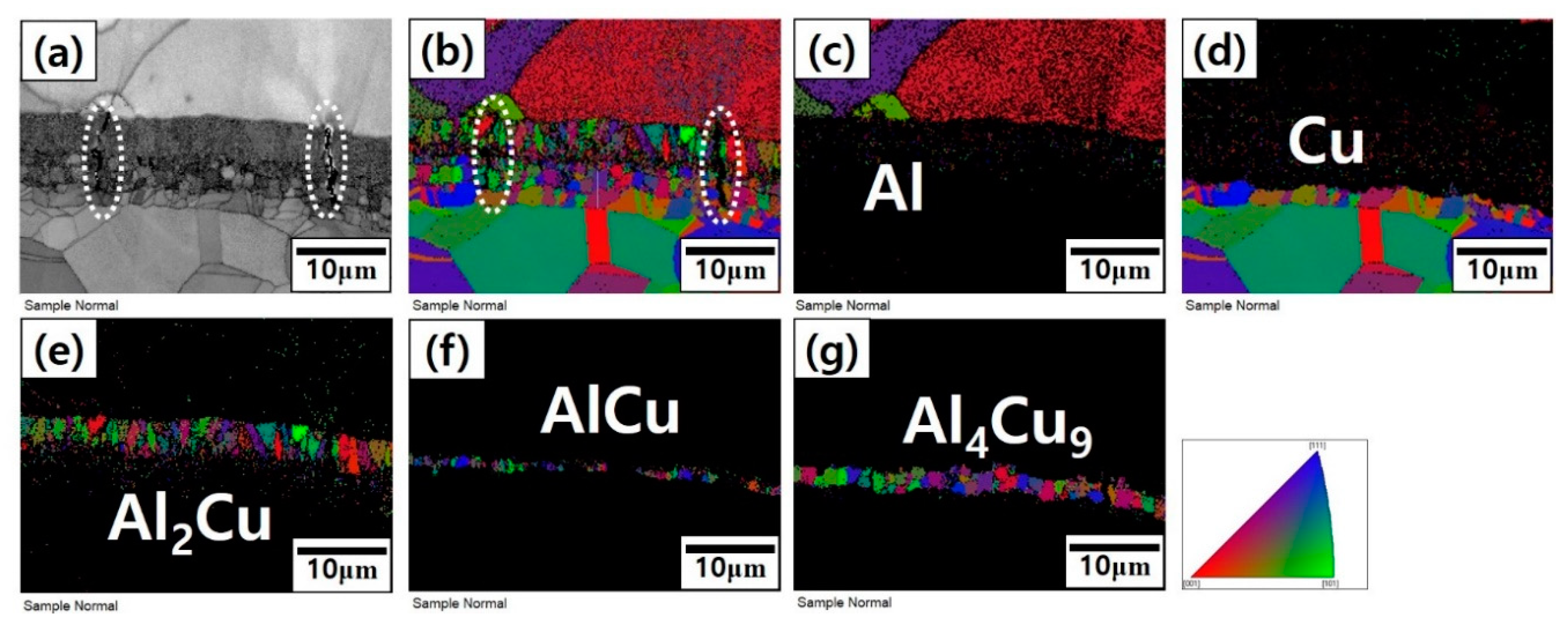
Figure 9.
SEM (a) and EBSD (b–g) images of the interface region in the vicinity of the tip of the propagating crack along the intermetallic layer for the Cu/Al/Cu composite plate heat-treated at 450 °C: (a) image quality map; (b) orientation map of all phases; (c–g) orientation maps of individual phases in the order of Al, Cu, Al2Cu, AlCu, and Al4Cu9.

Figure 10.
SEM (a) and EBSD (b–g) images of the interface region in the vicinity of the tip of the propagating crack along the intermetallic layer for the Cu/Al/Cu composite plate heat-treated at 500 °C: (a) image quality map; (b) orientation map of all phases; (c–g) orientation maps of individual phases in the order of Al, Cu, Al2Cu, AlCu, and Al4Cu9.

Figure 11.
Stereoscopic microscopic images (a–f) and schematic illustration (g–l) of the interface region at the tip of the major crack propagating along the interface during the peel test of Cu/Al/Cu clad composite heat-treated at 500 °C for 3 h.
Figure 11.
Stereoscopic microscopic images (a–f) and schematic illustration (g–l) of the interface region at the tip of the major crack propagating along the interface during the peel test of Cu/Al/Cu clad composite heat-treated at 500 °C for 3 h.

Figure 12.
Variations of intermetallic compound (IMC) layer thickness, inter-crack spacing, and the peel strength as a function of heat treatment temperature.
Figure 12.
Variations of intermetallic compound (IMC) layer thickness, inter-crack spacing, and the peel strength as a function of heat treatment temperature.

© 2019 by the authors. Licensee MDPI, Basel, Switzerland. This article is an open access article distributed under the terms and conditions of the Creative Commons Attribution (CC BY) license (http://creativecommons.org/licenses/by/4.0/).
Share and Cite
MDPI and ACS Style
Kim, Y.K.; Hong, S.I. Effect of Intermetallic Compound Layer on Peel Strength and Crack Propagation Behavior in Cu/Al/Cu Clad Composites. Metals 2019, 9, 1155. https://doi.org/10.3390/met9111155
AMA Style
Kim YK, Hong SI. Effect of Intermetallic Compound Layer on Peel Strength and Crack Propagation Behavior in Cu/Al/Cu Clad Composites. Metals. 2019; 9(11):1155. https://doi.org/10.3390/met9111155
Chicago/Turabian StyleKim, Yong Keun, and Sun Ig Hong. 2019. "Effect of Intermetallic Compound Layer on Peel Strength and Crack Propagation Behavior in Cu/Al/Cu Clad Composites" Metals 9, no. 11: 1155. https://doi.org/10.3390/met9111155
Note that from the first issue of 2016, this journal uses article numbers instead of page numbers. See further details here.