Copper Clad Steel Strips Produced by a Modified Twin-Roll Casting Process

Institute of Metal Forming, RWTH Aachen University, 52072 Aachen, Germany
*
Author to whom correspondence should be addressed.
Metals 2019, 9(11), 1156; https://doi.org/10.3390/met9111156
Submission received: 12 September 2019
/
Revised: 21 October 2019
/
Accepted: 22 October 2019
/
Published: 28 October 2019
(This article belongs to the Special Issue Clad Metals: Fabrication, Properties and Applications)
Abstract
:Twin-roll strip casting of steel provides a resource and energy efficient way to produce thin hot strips directly from the liquid phase. Clad metals offer less costly alternatives to monolithic alloys for a wide range of applications, but their various production routes are extensive, expensive, or slow. In order to exploit the strengths of twin-roll strip casting to provide a possibly more cost and energy efficient production route for clad thin strips, research into the expansion of twin-roll strip casting process is conducted. The aim of the current research is the combination of steel with copper. For this purpose, a prefabricated cladding strip of commercially pure copper is inserted into the twin-roll strip casting process. Bonding between the copper strip and the cast steel strip (DC01) is realized by exploiting the process heat. The bonding zone of the clad strip is subsequently analyzed under the optical microscope and in the electron micro probe analyzer. The imagery shows an irregular bonding interface with straight and locally altered regions alternating. These irregularities can be classified into four groups based on their morphology and suspected forming mechanism. Bond strength and formability of the clad strips is qualitatively examined in rolling and bending tests. Rolling was possible without delamination and a total height reduction of approx. 40% while defect-free bending of 2 mm and 3 mm thick specimens was possible up to a bending angle of 90° for a bending radius of 5 mm.
1. Introduction
Clad metals are composites with a layered structure and offer a simple way to combine the properties of different metals and alloys. Individual properties, e.g., ultimate tensile strength or fracture resistance, of certain clad metal combinations can even surpass the ones of their respective base materials [1]. Hence, typical applications for clad metals are lightweight applications, corrosion protection, and as substitutes for more expensive materials. Thin flat products are mainly clad by roll bonding where possible material combinations are limited by the differences in flow behavior of materials [2]. Additionally, for cold roll bonding, a high reduction of thickness is imperative [3], which results in high process forces and therefore cold roll bonding is often limited to narrow strip widths.
By combining casting and rolling into a single process step, twin-roll strip casting (TRC) eliminates many intermediate process steps and offers a short, fast, and economical production route for flat products [4]. Basically, melt is poured between two counter-rotating casting rolls, which act as moving mould. On the casting roll surfaces, the melt solidifies to two shells which are subsequently rolled together in the roll nip. The solidification can be divided into four stages which correspond to four areas within the melt pool according to Kopp et al. [5]: In Area I, where melt is in direct contact with the casting rolls; Area II, shell growth region; Area III, hydrodynamic rolling of the mushy zone; Area IV, fully solidified strip. A schematic depiction is shown in Figure 1a. Using twin-roll casting to create clad strip offers huge potentials in process shortening while simultaneously addressing the short comings of roll and explosive bonding, and laser cladding [6,7]. The driving idea hereby is to exploit the process heat to create bonding between the individual layers.
Clad strips consisting of different aluminium alloys made by twin-roll casting have been examined by Haga et al. [8,9,10]. They demonstrated the feasibility of several caster designs using different two melt feeding systems, a split melt pool, and a tandem set-up. Grydin et al. [11,12] used a different approach. Here, a prefabricated steel strip was inserted laterally into the melt pool. Subsequently, the solidifying cast aluminium strip is welded under high pressure onto the steel strip within the roll gap.
The combination of different steel alloys in a modified twin-roll casting process has been investigated before. Here, cladding was successfully realized by laterally inserting a prefabricated strip via the casting roll surface into the melt pool, see schematic in Figure 1b, and exploiting the process heat to create the bond [13,14]. The aim of current research is the expansion of this process to the combination of non-ferrous metals with a cast steel strip.
Thin copper clad steel strips are often used for electric parts and in heat exchangers, and are usually produced by cold roll bonding [15]. Usually, commercially demanded thickness dimensions range between 0.5 mm to 3.0 mm. Therefore, this combination is well suited to be adapted to the clad casting process route. However, because copper strips have a high thermal capacity and conductivity and at the same time a low melting point compared to steel, using these strips is technically challenging. Thus, the objective of this work is to adapt the twin-roll strip casting process to create a copper-steel composite strip and investigate the bonding interface of the clad strip.
2. Materials and Methods
2.1. Caster and Casting Experiments
Casting experiments were conducted on a laboratory scale vertical twin-roll caster comprising of two internally water-cooled casting rolls made out of copper with a diameter of 580 mm and a width of 150 mm. These casting rolls are nickel-coated and possess a shot-blasted surface. This stochastically structured surface ensures homogeneous solidification of the melt during the process [4]. Melt is fed via a submerged entry nozzle (SEN) between the casting rolls and forms the melt pool in this gap. This pool is contained in axial direction by ceramic side dams. An induction furnace with a capacity of up to 180 kg of steel melt supplies the whole system. This set-up allows casting of 0.8 mm to 3.5 mm thick strips up to a length of 100 m on the caster.
The cladding strip is inserted with the help of a feeding system. The system has three main functions. First, it provides a continuous feeding of the cladding strip. Second, it guides the cladding strip into the pool, ensuring the strip does not collide with the side dams to prevent leaking. In addition, third, it keeps the strip tension thereby maintaining the contact between cladding strip and casting roll surface constant to ensure stable process conditions and also compensates the unwinding coil. The feeding system is shown in Figure 2a. A force measurement is installed in the support of the second pulley, which records the vertical load on the support. The defined angles at the second pulley allow for the calculation of the strip tension. The brake is activated pneumatically, and, by changing air pressure, braking torque, and, therefore, strip tension can be adjusted.
Process parameters were determined and the cladding strip thickness was selected on the basis of finite element (FE) simulations using a one-dimensional heat transfer model. Details on the model and the simulations can be found in previous works [14,16]. Contact time is the first important parameter derived from simulation results. This can be achieved with help of the shell growth (Figure 3a) by simply taking the time the solidifying shell needs to grow to approx. half the roll gap. However, here the first challenge arises. Since a strip narrower than the casting roll width was selected for easier alignment and positioning, the roll gap in the performed casting experiments possessed two different thicknesses, as schematically depicted in Figure 2b. Additionally, shell growth on the copper strip is much faster than shell growth on the casting rolls (Figure 3a) because the heat flow into the strip is much higher due to a better contact between melt and strip because of the smooth strip surface and the much higher heat transfer of copper compared with the nickel-coating of the casting rolls. This results in an unequal degree of solidification across the strip width. Furthermore, a higher degree of solidification in contact with the cladding strip leads to a higher deflection of the casting rolls; the effective roll gap widens, amplifying the effect of the unequal roll gaps and thereby affecting process stability. Therefore, a thin cladding strip thickness would be favorable in order to keep the gap difference small.
During the process, the cladding strip absorbs a part of the process heat and heats up because heat transfer from the strip into the casting roll is much lower than heat transfer from the melt into the strip. The aim is to reach a strip temperature similar to hot rolling to achieve good element diffusion to create a bond but lower than melting temperature to maintain the strip’s geometry. The temperature to which the cladding strip heats up to during the process depends on several influencing factors, e.g., contact time, contact conditions between strip and casting roll, etc. One that is easy to change and has a noticeable effect is the heat capacity of the strip since it is proportional to its mass. This can be done under the assumption of a nearly constant density for a constant strip width by changing its thickness. Therefore, the temperature development of the cladding strip surface in contact with the melt for several different strip thicknesses has been determined in the simulation (Figure 3b).
Taking shell growth, roll gap geometry, and cladding strip temperature development into account, the following process window was chosen. A cold-rolled, unalloyed copper strip (Cu-ETP) with a thickness of 1.2 mm and a width of 80 mm for easier strip positioning was used for the casting experiments. Contact time is varied between 0.3 s and 0.5 s, while the roll gap is varied between 1.8 mm and 3.0 mm resulting in theoretical possible thickness ratios between cladding and cast strip of 0.5:1 to 1.5:1. Strip tension was set to 100 N and the steel melt had a chemical composition of 0.12 mass-% C, 0.6 mass-% Mn, and 0.02 mass-% Si, well within the specification for DC01.
2.2. Strip Characterization
For the microscopic analysis of the bonding area, the cross-section of the strip in and perpendicular to the casting direction was examined with the optical microscope Leica DM2500 M (Wetzlar, Germany). The samples were cut out of the strip, prepared, and polished. The specimens were examined in their polished state and etched with 2% Nital.
Electron probe microanalysis (EPMA) was performed by a Schottky field emitter micro probe equipped with five wavelength-dispersive spectrometers. For the elemental distribution images and the line-scan measurements, the following conditions were applied: 100 nA beam current and 15 keV beam energy. Since carbon was quantified, special anticontamination devices, i.e., oxygen jet and nitrogen cooling plate, were used to reduce contamination effects. Characteristic X-ray intensities were detected and calibrated by the ones of standards. Using a matrix correction procedure elemental concentrations were calculated from the measured intensities.
The formability of the clad strip has been qualitatively analyzed in rolling and bending tests. Rolling tests were executed on a rolling mill for slit strips of up to 20 mm width. Using a four-high configuration with a work roll diameter of 45 mm, five as-cast strips samples with a length of 60 mm and a width of 12 mm were reduced to a target thickness of 2 mm.
Bending tests have been executed on a Trumpf Trumabend V 50 bending press (Ditzingen, Germany) in accordance with ISO 7438 [17]. Bending samples have the same size as the rolling samples, and the bending tool used has a radius of 5 mm. All samples were positioned with the steel side facing the bending tool.
3. Results
3.1. The Casting Process
As expected, the inhomogeneous cooling conditions within the melt pool led to a very narrow operating window with a contact time of approx. 0.5 s. Clad strip with a thickness ratio between steel and copper layer of approx. 1.5:1 and a final strip thickness of about 3 mm to 3.3 mm was produced. In case of a longer contact time, the cladding strip would, despite its contact with the casting roll, absorb too much energy and melt, which would end the cladding process. On the other hand, if the contact time was too short, the non-clad edges would not fully solidify. In this case, bleeding would occur, meaning the hot strip core would remelt the already solidified shell once it leaves the roll nip and therefore the contact with the cooling casting rolls. The process can be continued, but bleeding might lead to defective bonding or a defective clad strip by dripping or running over the clad part of the strip; see Figure 4. In the end, all clad strip sections were trimmed and for all following examinations only the clad fillet was used.
The surface of the cast side of the clad strip showed the typical as-cast appearance as a non-clad strip: matte grey surface with the casting roll surface texture partially embossed. Occasionally, hot cracks were found at the transition between clad and non-clad strip sections across the strip width. These are typical defects resulting from internal stress due to vastly inhomogeneous local heat flux during casting [4], in this case caused by the presence of the copper strip. On the cladding strip side too, the casting roll surface structure is partially embossed into the copper surface while the copper shows various tempering colors and oxidation.
The general feasibility of cladding steel strips with copper by the modified twin-roll casting process has been shown in casting experiments although the main challenge of controlling the disturbance of heat flux in the process created by the insertion of the copper strip has not fully been solved. To counter the effects of the difference in the roll gap, a custom-fit casting roll with a groove similar to the ones used to cast strips with tailored cross-sections [18] could be used. This could also prove beneficially concerning the aforementioned difficulties in solidification because of the altered heat flux.
3.2. Bonding Interface
Since the cladding process itself is not directly observable, the morphology of the bonding interface helps to draw conclusions about the bonding process. Imagery taken with an optical microscope is used to describe and classify the bonding interface and with the qualitative and quantitative information about the local chemical composition from the EPMA, material exchange across the interface can be made visible.
At first glance, the cross-section of the strip shows an irregular and non-uniform bonding interface, even to the naked eye, see Figure 5. Large parts of the interface present themselves as a sharp border between the two metals, a flat interface similar to the interface found in clad metals made by hot rolling [19,20]. However, in between are numerous different irregularities detectable. These irregularities can be grouped into four categories: cracks, local meltings, folds and intermixed regions.
3.2.1. Flat Interface
Starting with the flat interface, neither the polished nor the etched specimens show any remarkable features when inspected with the optical microscope; see Figure 6. Although in Figure 6a the asymmetric shell growth of the cast steel strip is well visible, the columnar grains are easily distinguishable from the equiaxed center that appears darker after etching.
The line-scans from the EPMA support the impression of the micrograph. Here, too, a sharp separation between the two metals is visible. An approx. 5 µm wide transition zone for the elements iron and copper at the interface can be seen in the line-scans (Figure 7a). This looks identical to the observations made on steel-steel pairings produced by the same method, where the main elements of those alloys formed a diffusion zone of roughly the same size [13].
The line-scan of the carbon concentration across the interface (Figure 7b) shows a penetration depth into the copper strip of about 70–80 µm. Clearly visible is an enrichment of carbon around the bonding interface of around 50 µm in both directions. These observations are also very similar to previous studies [13] and to those made on hot roll bonded clad strips [19,20]. The manganese concentration (not depicted) seems to not be affected at all by the cladding process.
3.2.2. Cracks
The first type or irregularities observed are little copper filled cracks along the grain boundaries in the cast strip as shown in Figure 8. They appear in irregular frequency and spacing. There are two possible explanations to their formation, and maybe both superimpose each other. First, surface cracks are a known defect in TRC-strips [4]. It is a problem that is predominant with smooth casting roll surfaces, or, in this case, the surface of the cladding strip. Liquid copper can enter these cracks and solidify inside. The second possible mechanism for their formation has been observed by Ishida [21]. He examined the influence of copper melt in contact with solid iron, the state presumably present at the interface, and these cracks are the result of grain-boundary penetration. The temperature at the interface had to be between 1100 °C and 1200 °C for grain-boundary penetration to occur. However, for both explanations, the copper strip has to melt at least locally at the interface, which is seemingly in contradiction with the simulation results. However, the simulation only takes the temperature development within the process until the cast strip leaves the roll nip into account. Once the clad strip leaves the roll nip, the cast layer possesses a core temperature higher than its edge temperature. Furthermore, the strip loses forced cooling by the casting rolls. Cooling via convection and radiation is much lower so that the heat trapped in the middle of the cast layer reheats the cooler edges. This can cause the copper layer to melt at the interface.
3.2.3. Localized Melting
The next irregularity observed are localized meltings. Here, both metals seem to have been in the liquid phase simultaneously. The outline of the interface in the microscopic imagery (Figure 9) resembles that of the flat interface suggesting no significant shear forces were present during this state. This can lead to the assumption the formation of these kind of irregularities took place in the melt pool. Two conditions have to be met for this to happen.
First, the copper strip has to melt locally. According to the simulation results, this should not happen. However, simulations assume constant and uniform contact conditions between the copper strip with the casting roll across width and along casting direction and time. Backward slip in the rolling stage of the process can cause the solidified shell, and, in this case, the copper strip, to lift and lose contact with the casting roll, resulting in a hot spot. This effect causes process oscillations and ripples through the solidified shell [22]. This can be enough to melt the surface of the copper strip. Furthermore, these are high-frequency oscillations, which the feeding device cannot compensate.
Second, the solidification of the steel melt cannot have been advanced too far. There still had do be a liquid fraction with which the copper melt could mix. This is supported by the fact of the absence of shear forces during mixing. Therefore, the formation of this irregularity has to occur very early in the strip casting process, somewhere in areas I and II.
3.2.4. Folds
An example of a fold is shown in Figure 10. A part of the steel shell is folded over as shown in the highlighted image on the right side of Figure 10. Clearly, significant shear forces were at work, which leads to the assumption the creation of these folds must occur in the melt pool close to the roll nip where shear forces are high [5].
The cause for this behavior lies probably in backward slip in the forming stage of the process as described in the previous paragraph. The main difference is that the shell has already fully solidified but does not possess much strength yet. Through shear forces, it is then pushed against the following cooler and harder strip and shell section creating the overlap of the shell and a pile up of copper. This is also the reason the copper layer can locally possess a thickness greater than the original thickness of the cladding strip.
3.2.5. Intermixed Region
At higher magnification, a roughly 25 µm to 30 µm wide interspersed zone along the interface can be occasionally observed, see Figure 11a—here, very obviously, copper and steel mixed. Once etched (Figure 11b), a strong and sharp separation between steel and the interspersed zone is visible, suggesting that the steel melt had fully solidified and both phases were not liquid at the same time. Another indication to support this is that no copper inclusions can be found in the steel layer. The wavy character of the mixture within this zone suggests that copper had liquefied at some point during the process.
The imagery and measurements from the electron microprobe analyzer (Figure 12 and Figure 13) is examined in purpose to gain a better understanding about the formation of the intermixed region. In the image taken by the scanning electron microscope (SEM) (Figure 12a), the intermixed region is clearly distinguishable. Looking more closely, two conspicuous features can be seen. The first one are spherical inclusions in the copper. This is the form in which iron typically segregates in a copper-rich phase [23]. This corresponds with the element mapping for copper and iron (Figure 12b,c) and the images from the microscopy (Figure 11). Second, directly at the edge between steel layer and intermixed region, a narrow band of a different color than the grey of steel and of copper is visible (marked in Figure 12a). This band widens towards the right side of the image into a vortex. This seems like an iron-rich phase (Figure 12c) in which carbon agglomerates noticeably (Figure 12d).
The copper and iron concentration across the interface are shown in Figure 13a. In the measured line, three iron precipitations are visible in the copper-rich intermixed region. The average iron content outside these precipitations is about 5 mass-%. On the steel facing side of the intermixed region, the iron-rich phase is visible. Over the distance of 3 µm, the element concentration stays constant, forming a step in the diagram, highlighted in Figure 13. Measured concentration for copper is approx. 16 mass-% and 83 mass-% for iron.
The carbon distribution (Figure 13b) looks similar to the one of the flat interface. Carbon diffused into the copper layer, although its penetration depth is with approx. 150 µm roughly twice as deep. However, its concentration is with 0.1 mass-% about half of the concentration at the flat interface. On the steel side for both interfaces, an enrichment of carbon about 0.2 mass-% at the interface can be found. The main difference is the intermixed zone. Here, the carbon concentration is about 0.3 mass-% except for the iron-rich band, highlighted in Figure 13, with a concentration of approx. 0.7 mass-%.
The exact formation of the intermixed region can still not be sufficiently explained by these observations. According to Ishida [21], interaction between the two metals takes place instantaneously and simultaneously. Atoms of the liquid copper diffuse into the grains of the iron via lattice diffusion. This is visible in the micrograph as a dark edge of the steel phase, which can be seen in Figure 9 and Figure 10 but is not present at the intermixed region. Parallel iron dissolution, as described by Yoshida [24] and also observed by Ishida [21], takes place. However, this usually includes a degeneration of the interface and in opposition to their findings a sharp interface between steel and intermixed region with no visible degradation is present in the microscopic imagery (Figure 11). Therefore, further research is needed.
The penetration depth of the process heat into the cladding strip can also be derived from micrograph. In Figure 14, the grains within the copper strip are identifiable. The fine grains of the formerly cold rolled copper strip are still visible at the edge. Going towards the bonding interface, the grain size changes quite abruptly to coarser ones. A significant grain growth from the interface up to a distance of approx. 500 µm in the copper strip is observed due to the heat.
3.3. Rolling and Bending Tests
All five specimens were cold-rolled in four to five passes to a final thickness of 2 mm resulting in a height reduction of approx. 35% to 40%. None of them showed any signs of delamination. The surface texture embossed by the casting rolls (Figure 15a) was completely eliminated, and the steel layer like the copper layer had a smooth cold rolled surface texture but oxides were still visible, compare with Figure 15b. Therefore, after rolling, the copper surface was pickled with 5% sulphuric acid for 30 s resulting in a shiny metallic surface (Figure 15c). Still defects are visible in the surface after pickling. The surface is laced with little craters. These are imprints of the oxides rolled into the material during cold rolling and dissolved by the pickling. A second pickling before cold rolling should eliminate these defects.
Looking at the micrograph of the rolled specimens, the morphology of the interface did not change (Figure 16a). Although macroscopically no delamination was detectable, occasionally defects could be found at the interface. Under the influence of the shear stresses during rolling, little holes emerge from the overlapping folds, see Figure 16b. It is visible that still a bit of copper is left in the fold and acts like a predetermined breaking point. They do not cause the bond to fail but are unwanted weak spots in the bond. On the other hand, neither cracks nor the intermixed zone were greatly influenced by the rolling operation (Figure 16c).
All bending samples, both as-cast and cold-rolled, were bent to an angle of 90° for a bending radius of 5 mm without delamination, see Figure 17a,b. In the bending area, a local thinning of the copper layer is visible. In Figure 17c, one can see a crack opening in the copper layer, which might be the result of work hardening. However, still the bond did not fail. These results support the impression of the rolling experiments of a good and moldable material bond.
4. Discussion
The bonding interface is the most important part of clad metals. Understanding its characteristics and formation is imperative to control the properties and quality of the final product. In case of the clad strips from the modified twin-roll casting process, the interface comprises of characteristics found in clad metals made by different production routes. Large parts of the interface appear flat and with a sharp boundary between the two layers in the micrograph. This is similar to the interface created by hot rolling. This flat interface is regularly interrupted by sections with a visible diffusion zone similar to the interface produced by laser cladding and welding. In both cases, diffusion of elements across the interface is the main bonding mechanism. Hereby, the element carbon with its high diffusion velocity at high temperatures is of major importance. By diffusing into the copper layer and agglomerating at the interface, it influences the bond creation. This corresponds with previously examined combinations produced by clad casting [13,14]. Thus, clad strips from the modified twin-roll casting process are a suitable alternative to clad strips produced by rolling, which was shown.
For the examined material pairing stable casting conditions could, as explained, for various reasons not be kept during the process. Therefore, the interface possesses manifold different characteristics. Despite the inhomogeneities in the bonding surface, the material bond showed good performance in the carried out forming tests. Neither the samples that have been cold rolled nor those that have been bent showed any signs of delamination. This shows that the bond possesses sufficient adhesion between the two cladding partners in spite of the occasional formation of defects at the interface. These defects form from folds at the interface, which are a result of process oscillations, which are generally an undesirable phenomenon. However, for a comprehensive evaluation of bond quality and strength quantitative testing, in the form of shear strength tests, has to be conducted besides the already performed qualitative testing. These tests are still pending.
In laser cladding, a minimal intermixed layer is needed to create a bond but a too big intermixed zone can be disadvantageous [25]. The same observation has been made in steel–steel pairings produced by the modified twin-roll casting process [26]. An option to create a more uniform bond across the strip could be by texturing the cladding strip before it comes into contact with the melt. This should evoke an effect similar to the one of the shot-blasted surface of the casting rolls. A conceivable technical solution could be in-line brushing with a steel brush to create microscopic bruising of the surface. The desired effects would be:
- A stochastically structured surface leading to a more homogeneous solidification of the melt and a cast strip with less defects. This should also help to form a more uniform bonding interface.
- Defined peaks in roughness to melt and mix with the steel phase and therefore creating a defined intermixed region between the two cladding partners.
5. Conclusions
The results from the current research can be summarized as follows:
- It was shown that it is possible to create copper clad steel strips via the modified twin-roll casting route. Strips with a thickness ratio between cast and cladding strip of roughly 1.5:1 and a final thickness between 3.0 mm and 3.3 mm were produced this way.
- Due to copper’s thermal properties and their influence on the process, it was not possible to keep stable casting conditions for longer time periods. To achieve this, constructional adaptation of the experimental set-up and maybe a change in process control are needed to counter process oscillations.
- The unstable bonding conditions lead to a multitude of different characteristics within the bonding interface. However, for all different characteristics, bonding was achieved by element diffusion, and any mechanical locking was of minor importance to the bond. Especially important hereby was the diffusion of carbon, which agglomerated at the bonding interface.
- Despite the resulting irregular morphology of the bonding interface, the bond performed well in rolling and bending tests.
Author Contributions
Supervision, G.H.; writing – original draft, D.M.
Funding
This research was funded by Deutsche Forschungsgemeinschaft (DFG, German Research Foundation)-project-ID 258 106 764.
Acknowledgments
The authors would like to thank Silvia Richter of the Central Facility for Electron Microscopy (GfE) at the RWTH Aachen University for her support with the EPMA.
Conflicts of Interest
The authors declare no conflict of interest.
Abbreviations
The following abbreviations are used in this manuscript:
| TRC | Twin-roll (strip) casting |
| Cu | Copper |
| Fe | Iron |
| C | Carbon |
| FE | Finite Element |
| SEN | Submerged entry nozzle |
| EPMA | Electron probe microanalysis |
| SEM | Scanning electron microscope |
References
- Lesuer, D.R.; Syn, C.K.; Sherby, O.D.; Wadsworth, J.; Lewandowski, J.J.; Hunt, W.H. Mechanical behavior of laminated metal composites. Int. Mater. Rev. 1996, 41, 169–197. [Google Scholar] [CrossRef]
- Bambach, M.; Pietryga, M.; Mikloweit, A.; Hirt, G. A finite element framework for the evolution of bond strength in joining-by-forming processes. J. Mater. Process. Technol. 2014, 214, 2156–2168. [Google Scholar] [CrossRef]
- Jamaati, R.; Toroghinejad, M.R. Cold roll bonding bond strengths: Review. Mater. Sci. Technol. 2013, 27, 1101–1108. [Google Scholar] [CrossRef]
- Ferry, M. Direct Strip Casting of Metals and Alloys: Processing, Microstructure and Properties; Woodhead Publishing in Materials, Woodhead Pub. and Maney Pub. on Behalf of The Institute of Materials, Minerals & Mining: Cambridge, UK, 2006; ISBN 9781845690496. [Google Scholar]
- Kopp, R.; Hagemann, F.; Hentschel, L.; Schmitz, J.; Senk, D. Thin-strip casting—Modelling of the combined casting/metal-forming process. J. Mater. Process. Technol. 1998, 80–81, 458–462. [Google Scholar] [CrossRef]
- Li, L.; Yin, F.X.; Nagai, K. Progress of Laminated Materials and Clad Steels Production. Mater. Sci. Forum 2011, 675–677, 439–447. [Google Scholar] [CrossRef]
- Santo, L. Laser cladding of metals: A review. Int. J. Surf. Sci. Eng. 2008, 2, 327. [Google Scholar] [CrossRef]
- Haga, T.; Nakamura, R.; Kumai, S.; Watari, H. Clad strip casting by a twin roll caster. Arch. Mater. Sci. Eng. 2009, 37, 117–124. [Google Scholar]
- Haga, T.; Watari, H. Casting of Clad Strip by a Vertical Type Twin Roll Caster. Manuf. Sci. Technol. 2015, 3, 197–203. [Google Scholar]
- Nakamura, R.; Yamabayashi, T.; Haga, T.; Kumai, S.; Watari, H. Roll caster for the three-layer clad-strip. Arch. Mater. Sci. Eng. 2010, 41, 112–120. [Google Scholar]
- Grydin, O.; Gerstein, G.; Nürnberger, F.; Schaper, M.; Danchenko, V. Twin-roll casting of aluminum–steel clad strips. J. Manuf. Process. 2013, 15, 501–507. [Google Scholar] [CrossRef]
- Grydin, O.; Stolbchenko, M.; Schaper, M. Impact of steel substrate preheating on microstructure and properties of twin-roll cast aluminium-steel clad strips. Procedia Eng. 2017, 207, 1695–1700. [Google Scholar] [CrossRef]
- Vidoni, M.; Ackermann, R.; Richter, S.; Hirt, G. Production of Clad Steel Strips by Twin-Roll Strip Casting. Adv. Eng. Mater. 2015, 17, 1588–1597. [Google Scholar] [CrossRef]
- Münster, D.; Vidoni, M.; Hirt, G. Effects of Process Parameter Variation on the Bonding Strength in Clad Steel Strips by Twin-Roll Strip Casting. Mater. Sci. Forum 2016, 854, 124–130. [Google Scholar] [CrossRef] [Green Version]
- Köhler, M. Merkblatt 383—Plattiertes Stahlblech. Available online: https://www.stahl-online.de/wp-content/uploads/2019/04/MB383_Plattiertes_Stahlbech.pdf (accessed on 24 October 2019).
- Vidoni, M.; Daamen, M.; Hirt, G. Numerical and Experimental Investigation of a Modified Twin Roll Strip Casting Process for the Production of Clad Steel Strips. Key Eng. Mater. 2015, 651–653, 689–694. [Google Scholar] [CrossRef]
- DIN Deutsches Institut für Normung e. V. Metallische Werkstoffe - Biegeversuch; Beuth Verlag GmbH: Berlin, Germany, 2016; 77.040.10 (DIN EN ISO 7438). [Google Scholar]
- Vidoni, M.; Mendel, A.; Hirt, G. Profile Strip Casting with Inline Hot Rolling: Numerical Simulations for the Process Chain Design. Key Eng. Mater. 2014, 611–612, 1568–1575. [Google Scholar] [CrossRef]
- Wang, S.; Liu, B.X.; Chen, C.X.; Feng, J.H.; Yin, F.X. Microstructure, mechanical properties and interface bonding mechanism of hot-rolled stainless steel clad plates at different rolling reduction ratios. J. Alloy Compd. 2018, 766, 517–526. [Google Scholar] [CrossRef]
- Liu, B.X.; An, Q.; Yin, F.X.; Wang, S.; Chen, C.X. Interface formation and bonding mechanisms of hot-rolled stainless steel clad plate. J. Mater. Sci. 2019, 54, 11357–11377. [Google Scholar] [CrossRef]
- Ishida, T. The interaction of molten copper with solid iron. J. Mater. Sci. 1986, 21, 1171–1179. [Google Scholar] [CrossRef]
- Badowski, M.; Hentschel, L.; Kopp, R.; Schmitz, W.; Senk, D. Strip formation and process stability in twin roll strip casting. Steel Res. 2001, 72, 484–489. [Google Scholar] [CrossRef]
- Lu, X.; Cao, C.; Wei, B. Microstructure evolution of undercooled iron–copper hypoperitectic alloy. Mater. Sci. Eng. A 2001, 313, 198–206. [Google Scholar] [CrossRef]
- Yoshida, T.; Ohmura, H. Dissolution and Deposit of Base Metal in Dissimilar Metal Brazing. Weld. J. 1985, 64, 1–12. [Google Scholar]
- Hofman, J.T.; de Lange, D.F.; Pathiraj, B.; Meijer, J. FEM modeling and experimental verification for dilution control in laser cladding. J. Mater. Process. Technol. 2011, 211, 187–196. [Google Scholar] [CrossRef]
- Münster, D.; Zhang, B.; Hirt, G. Processing of Clad Steel Strips Consisting of a High Manganese and Stainless Steel Pairing Produced by Twin-Roll Casting. Steel Res. Int. 2017, 88, 1600285. [Google Scholar] [CrossRef]
Figure 1.
(a) Schematic depiction of the TRC (twin-roll strip casting) process and solidification within the melt pool, taken from [5]; (b) schematic depiction of clad casting.
Figure 1.
(a) Schematic depiction of the TRC (twin-roll strip casting) process and solidification within the melt pool, taken from [5]; (b) schematic depiction of clad casting.

Figure 2.
(a) Feeding system for the cladding strip before the casting experiment; (b) schematic depiction of the casting roll gap of the modified twin-roll casting process.
Figure 2.
(a) Feeding system for the cladding strip before the casting experiment; (b) schematic depiction of the casting roll gap of the modified twin-roll casting process.

Figure 3.
Simulated results: (a) shell growth of the solidifying melt in contact with the cladding strip and in contact with the casting rolls; (b) temperature development of the cladding strip surface in contact with the melt during casting.
Figure 3.
Simulated results: (a) shell growth of the solidifying melt in contact with the cladding strip and in contact with the casting rolls; (b) temperature development of the cladding strip surface in contact with the melt during casting.
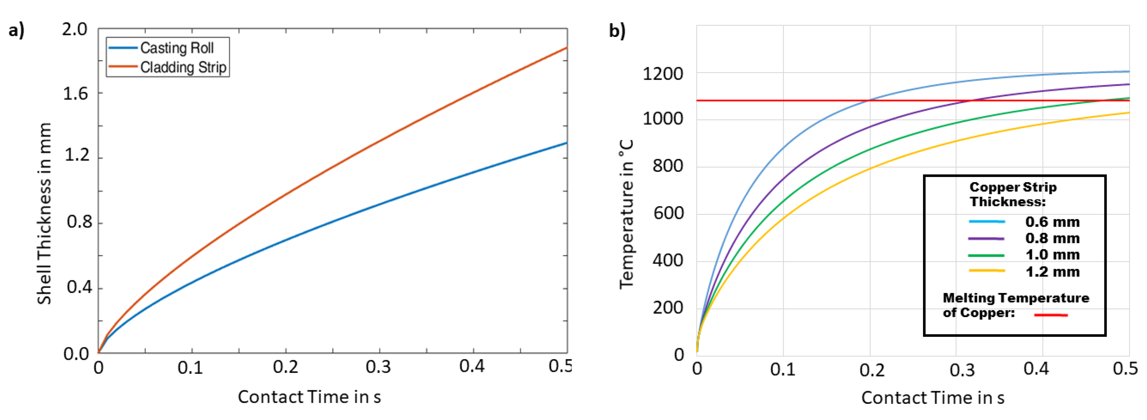
Figure 4.
Strip section of copper clad steel showing defect-free clad section between the dashed lines and different defects. 1: edge defects through bleeding and bulging; 2: hot cracks at the transition between clad strip and non-clad edges; 3: partially melted copper surface after steel melt bled over it; 4: Steel melt droplets.

Figure 5.
Polished cross-section of an as-cast copper clad steel strip showing the bonding interface.
Figure 5.
Polished cross-section of an as-cast copper clad steel strip showing the bonding interface.

Figure 6.
Microscopic images of the flat interface after etching: (a) at 25× magnification (b) at 200× magnification, each with DC01 at the top and copper at the bottom.
Figure 6.
Microscopic images of the flat interface after etching: (a) at 25× magnification (b) at 200× magnification, each with DC01 at the top and copper at the bottom.

Figure 7.
Line-scans from the EPMA of the flat interface: (a) iron and copper concentration across the interface and enlargement of the transition at the interface; (b) carbon concentration across the interface.
Figure 7.
Line-scans from the EPMA of the flat interface: (a) iron and copper concentration across the interface and enlargement of the transition at the interface; (b) carbon concentration across the interface.

Figure 8.
Bonding interface with copper filled crack at 100× magnification.
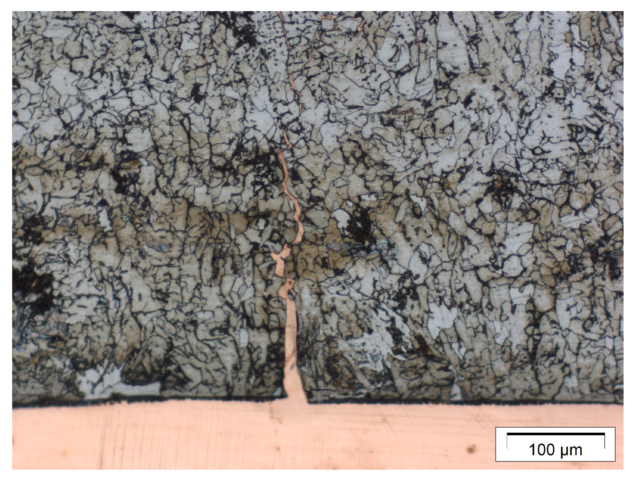
Figure 9.
Images of the bonding interface showing localized melting and mixing of the two cladding partners.
Figure 9.
Images of the bonding interface showing localized melting and mixing of the two cladding partners.
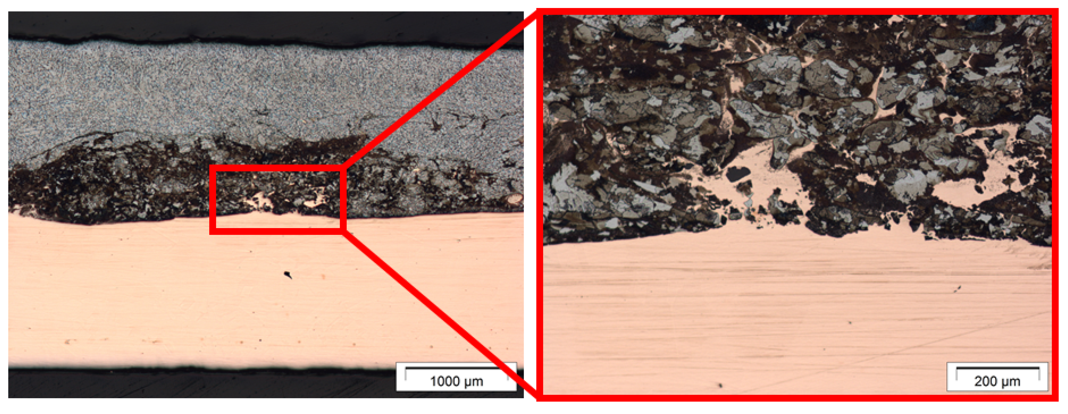
Figure 10.
Images from the microscopy of a fold in the bonding interface.
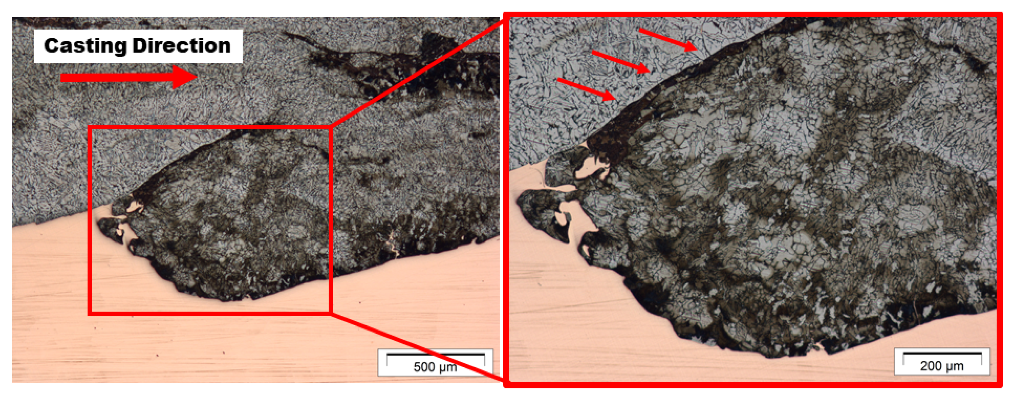
Figure 11.
Micrograph of an intermixed region at 100× magnification: (a) polished; (b) etched—both showing steel at the top and copper at the bottom.
Figure 11.
Micrograph of an intermixed region at 100× magnification: (a) polished; (b) etched—both showing steel at the top and copper at the bottom.

Figure 12.
(a) SEM image of an intermixed interface; (b) corresponding element mapping of copper; (c) corresponding element mapping of iron; (d) corresponding element mapping of carbon.
Figure 12.
(a) SEM image of an intermixed interface; (b) corresponding element mapping of copper; (c) corresponding element mapping of iron; (d) corresponding element mapping of carbon.

Figure 13.
Line-scans of the intermixed interface: (a) iron and copper (b) carbon.
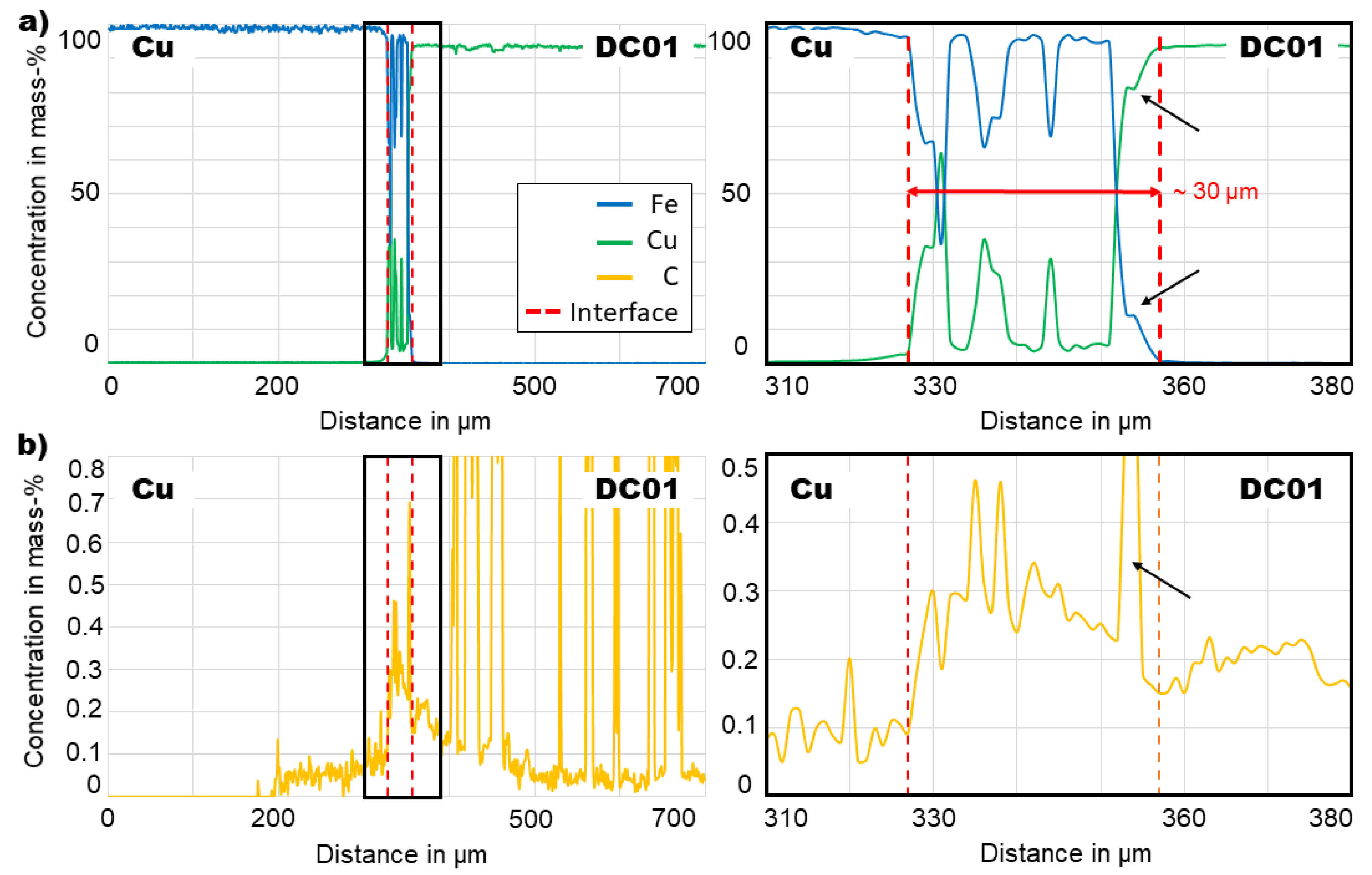
Figure 14.
Grain structure within the copper layer of the clad strip. Bonding interface is found towards the top.
Figure 14.
Grain structure within the copper layer of the clad strip. Bonding interface is found towards the top.

Figure 15.
Copper surface of the clad strip: (a) after casting; (b) after rolling; (c) after pickling.
Figure 15.
Copper surface of the clad strip: (a) after casting; (b) after rolling; (c) after pickling.

Figure 16.
(a) Micrograph of a cold-rolled specimen; (b) holes in the interface at 200× magnification; (c) intermixed zone and crack at 100× magnification.
Figure 16.
(a) Micrograph of a cold-rolled specimen; (b) holes in the interface at 200× magnification; (c) intermixed zone and crack at 100× magnification.
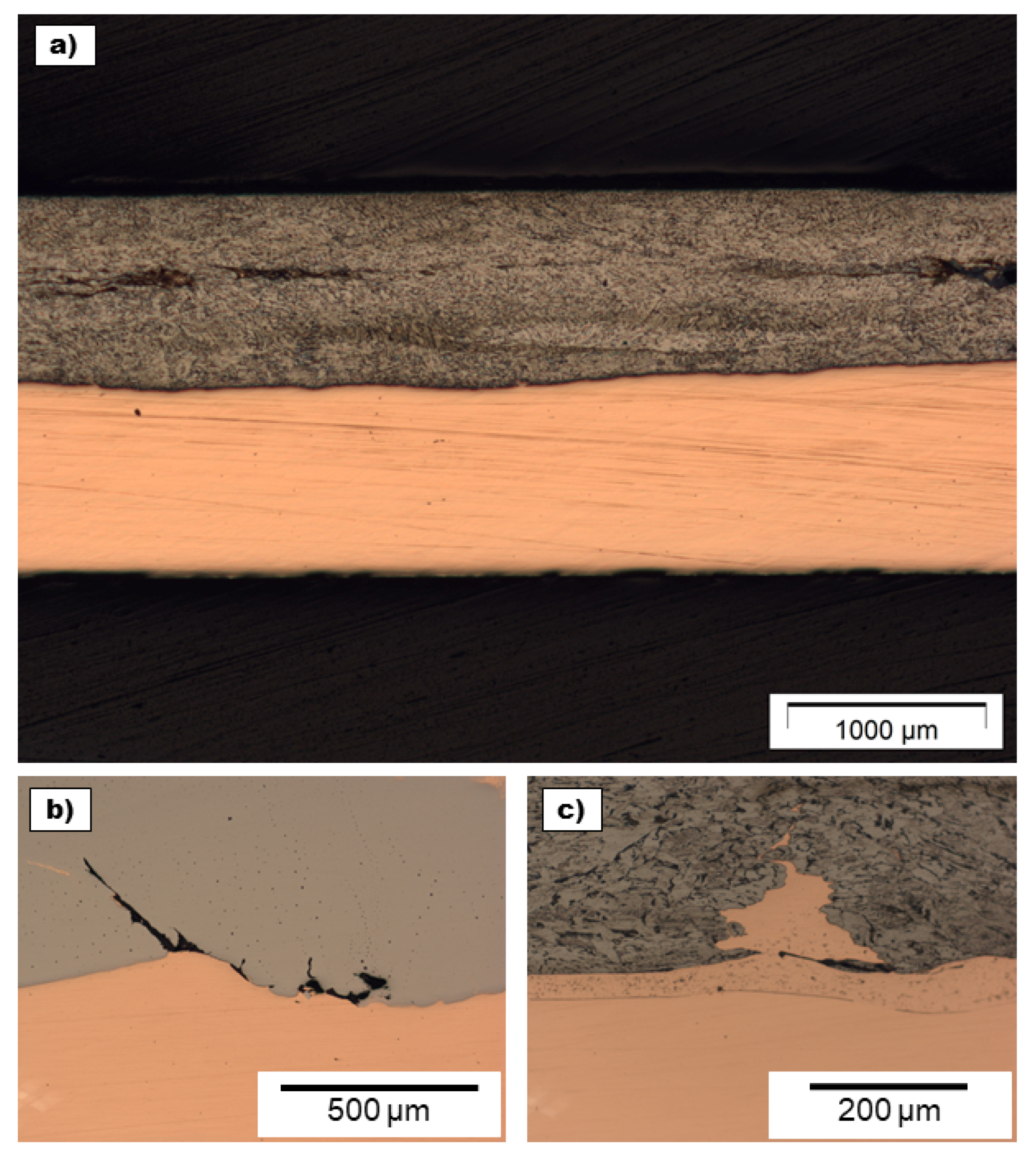
Figure 17.
(a) Microscopic image of the bending area; (b) side view onto a bend specimen; (c) front view onto a bend specimen.
Figure 17.
(a) Microscopic image of the bending area; (b) side view onto a bend specimen; (c) front view onto a bend specimen.

© 2019 by the authors. Licensee MDPI, Basel, Switzerland. This article is an open access article distributed under the terms and conditions of the Creative Commons Attribution (CC BY) license (http://creativecommons.org/licenses/by/4.0/).
Share and Cite
MDPI and ACS Style
Münster, D.; Hirt, G. Copper Clad Steel Strips Produced by a Modified Twin-Roll Casting Process. Metals 2019, 9, 1156. https://doi.org/10.3390/met9111156
AMA Style
Münster D, Hirt G. Copper Clad Steel Strips Produced by a Modified Twin-Roll Casting Process. Metals. 2019; 9(11):1156. https://doi.org/10.3390/met9111156
Chicago/Turabian StyleMünster, Dennis, and Gerhard Hirt. 2019. "Copper Clad Steel Strips Produced by a Modified Twin-Roll Casting Process" Metals 9, no. 11: 1156. https://doi.org/10.3390/met9111156
Note that from the first issue of 2016, this journal uses article numbers instead of page numbers. See further details here.