Shear Punching of Amorphous Alloys under High-Frequency Vibrations

College of Mechatronics and Control Engineering, Shenzhen University, Shenzhen 518060, China
*
Author to whom correspondence should be addressed.
Metals 2019, 9(11), 1158; https://doi.org/10.3390/met9111158
Submission received: 6 September 2019
/
Revised: 21 October 2019
/
Accepted: 24 October 2019
/
Published: 28 October 2019
(This article belongs to the Special Issue Amorphous Alloys — Properties, Modeling and Applications)
Abstract
:Although amorphous alloys possess many excellent properties, their practical application is limited due to the difficulty of plastic forming. In this work, an effective shear punching of amorphous alloys under high-frequency vibrations was proposed. Under the high-frequency vibration of the punch, the plastic powder was melted into a flexible punch due to the frictional heat generation effect and the viscoelastic heat effect and continued to flow downward under the extrusion of the ultrasonic head to plastically deform the amorphous alloy ribbon. The disordered structure of the amorphous alloys helps them get soft in a localized region during high-frequency vibrations, which can result in low-stress deformations that are different from amorphous alloys in the conventional state. We manufactured various shapes with area of 5 mm2 using high-frequency vibrations and a molten plastic viscous medium. The molds were shaped into the letters “B”, “M”, and “G” and the Chinese characters “工” and “大”. The shapes were made from Fe-based, Al-based, La-based, and Cu-based amorphous alloys. Our results show that shear punching of amorphous alloys under high-frequency vibrations is an effective and low-cost production method of amorphous alloy, which also provides a basis for the wide application of amorphous alloy.
1. Introduction
Metallic glass is a new type of material discovered by American scientists through ultra-fast cooling nearly 70 years ago [1]. Because of its excellent properties, such as corrosion resistance, high strength, and high hardness [2,3,4,5], it rapidly attracted extensive attention in the material science field [6,7,8,9]. However, like every material, metallic glass has its weaknesses. The disordered arrangement of internal atoms gives it a high hardness, but also a metastable state. Moreover, its fracture behavior is different from the traditional fracture criterion [10]. In amorphous alloys without grain boundary and crystal structure, the local shear band is prone to shear where the stress exceeds its yield strength, and the crack propagation of the shear band will cause it to break. Due to this flaw, amorphous alloys are difficult to manufacture through conventional plastic forming such as shear punching, forging, etc. [11,12,13].
Ultrasound refers to sound waves with a vibration frequency above 20 kHz. Introducing ultrasonic vibration into the traditional metal-plastic forming process has the following advantages: Reducing the friction between the workpiece and the mold, improving the plastic forming ability of the metal material, and obtaining better surface quality and high-dimensional accuracy of the product [14,15,16]. Therefore, local and foreign scholars have carried out extensive research and have applied ultrasonic vibration technology to the processes of drawing, punching, extrusion, and rolling. Shear punching is the process of separating and forming a product using a mold in a specific area [17]. Due to its convenience, low cost, and availability, it is widely used in manufacturing processes, and many materials have been manufactured by shear punching, such as Al and Cu [18,19]. In the field of manufacturing amorphous alloys, shear punching is mainly concentrated in the manufacturing process of macroscopic scale [20]. Due to the high strength and high hardness characteristics of amorphous alloys, large force is required [21], causing energy waste and low precision. Further processing may also be required, which leads to cost increase, while the shape of the molded product remains relatively simple.
In this paper, a new effective amorphous alloy shearing method was proposed. The method mainly uses ultrasonic vibration with molten plastic. During the experiment, the energy of ultrasonic vibration was used to melt the viscous medium of the molten plastic and soften the contact area of the amorphous alloy during the punching process, which achieved relatively small pressure and formed a complexly shaped product. Fe-based, Al-based, La-based, and Cu-based amorphous alloys of various shapes of letters and symbols were obtained in a region of 5 mm2 by shear punching using an amorphous alloy under high-frequency vibration. Molds were shaped to form the letters “B”, “M”, and “G” and Chinese characters “工” and “大”. The results show that shear punching of amorphous alloy under high-frequency vibration is an effective and low-cost method for producing amorphous alloy parts [22].
2. Experimental Procedure
2.1. Experimental Setup
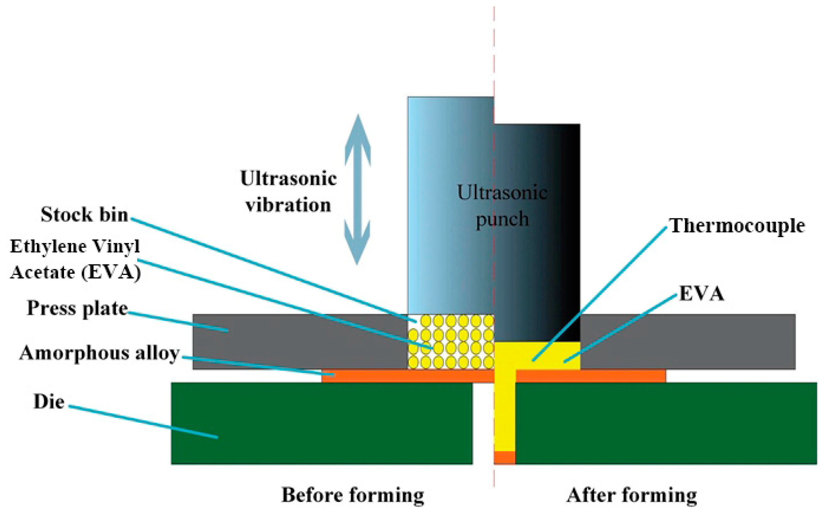
The punching method proposed here is suitable for various amorphous alloys. The schematic of shear punching of amorphous alloy under high-frequency vibration is shown in Figure 1. First, we placed an amorphous alloy ribbon with size of 10 × 10 mm2 above the mold. The pressure plate with a bin was located above the amorphous alloy. Then, we filled the stock bin hole with a spherical powder (ethylene vinyl acetate; EVA), which had an average diameter of 0.3 mm, or about 50 mm3. Ultrasonic waves were applied when the punch was lowered to the specified height. Under ultrasonic vibrations, the plastic powder rapidly rose to a high temperature and melted into fluid, which acted as a pressure transfer medium to induce the amorphous alloy shear forming and, finally, to obtain the expected product. In this experiment, the 2020 ultrasonic plastic welding machine produced by Shenzhen Hongri Ultrasonic Equipment Co., Ltd. (Shenzhen, China) was used. The ultrasonic amplitude and frequency used in the experiment were 40 um and 20 kHz, respectively, ultrasonic vibration duration was 1 s, air pressure was 0.6–0.7 MPa, and holding pressure was 2–4 s. The clearance between ultrasonic punch and pressing plate was 0.15 mm, which ensured good sealing to EVA. Measurements showed that the size of the silo was 5.3 mm and the height of the silo was 5 mm. The weight of EVA powder, which filled in the silo, was about 15 mg. After the experiment, the thickness of gelatinous EVA changed from 5 mm to 2 mm. EVA easily forms a flexible punch because it has a relatively low melting point, is easily melted into a gel form under the heat generated by high-frequency vibration, and has good viscosity. In addition, the gel-like EVA is easily dropped from the amorphous alloy sample, and the EVA which is not dropped can be gently removed by the tweezers. Previous studies have shown that when the powder enters a fluid state, it can not only act as a pressure transfer medium, but can also transmit ultrasonic waves to amorphous alloys, resulting in the softening of specific regions, which follows a different punching mechanism from conventional materials [23].
2.2. Materials
In this work, we used La55Al25Ni5Cu10Co5, Al86Ni9La5, La60Al20Ni20, Fe78Si9B13, and Cu50Zr50 (at.%) amorphous alloy ribbons with an average thickness of 80, 60, 50, 30, and 50 μm, respectively, manufactured using the belt-throwing machine. Their glass transition temperature (Tg) and crystallization temperature (Tx) were measured by differential scanning calorimetry (DSC) images, respectively, as shown in Table 1. Due to different glass transition temperatures, supercooled liquid region properties, amorphous alloy strips of each matrix properties, and viscosity, the thickness of the amorphous alloy strips will vary while manufacturing. It is difficult to process amorphous alloys through conventional plastic processing at room temperature because they possesses high hardness and lack of plasticity [24]. In this experiment, the used amorphous alloy ribbons were cut into square sheets with a side length of 10 mm.
2.3. Characterizations
As shown in Figure 2, the microscopic appearance of samples after shear punching of amorphous alloys under high-frequency vibration was tested on a scanning electron microscope (SEM; QUANTA FEG 450, FEI, Hillsboro, OR, USA) instrument. The length and width of the mold “B”, “M”, “G”, and two other Chinese characters, “工” and “大”, were almost 5 mm. As shown in Figure 3, thermocouples (TC-TT-K-36-36, OMEGA, Biel, Switzerland) and data acquisition modules from NI (USB 9213, National Instruments, Austin, TX, USA) were used to measure the temperature of the powder in the stock bin. The glassy nature of amorphous alloys plates before and after the shear punching of the amorphous alloy under high-frequency vibration was tested using standard X-ray diffraction (XRD; MiniFlex600, Rigaku, Tokyo, Japan) with Cu Kα radiation and differential scanning calorimetry (DSC; DSC-8000, Perkin-Elmer, Waltham, MA, USA) at a heating rate of 20 K/min.
3. Results and Discussions
3.1. SEM Image of the Samples
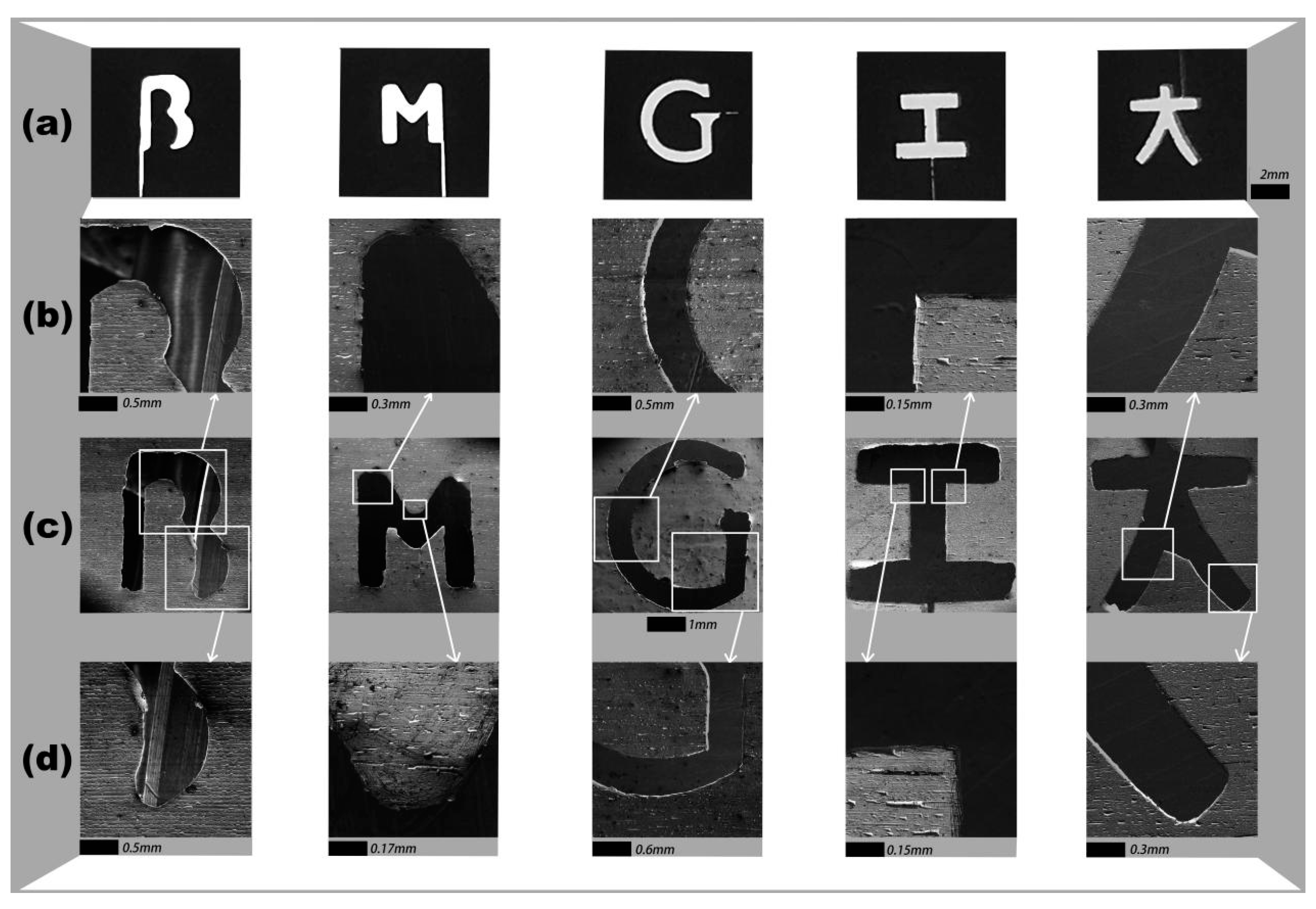
The proposed shear punching of amorphous alloys under high-frequency vibration is a low-cost plastic forming method suitable for a series of amorphous alloys. In order to see the surface material fracture characteristics more intuitively, the formed Fe-based, Al-based, La-based, and Cu-based products were scanned by SEM to show “B”, “M”, “G”, and two other Chinese characters, “工” and “大”. In Figure 2a, the mold prepared by low-speed wire electric discharge machining are shown, while Figure 2c shows an SEM image of an amorphous alloy product manufactured using this method. Using the same scale, Figure 2b,c shows a partial magnified SEM image of the products. The area of the die was Sm and the area of the sample was Sx (x represents the sample of each matrix amorphous alloy, such as Fe78Si9B13), which was substituted into the formula
Through calculation, the results show that the similarity between the amorphous alloy sample and the die is mostly 95%. The results show that this method can be used alloy fine products.
3.2. Experiment Mechanism
Amorphous alloys differ from conventional metals in their structures and properties, which are considered to be a combination of elastic matrix and dispersed sites. Due to this unique structure, a specific liquid-like region was coupled to the high-frequency hammer energy during the experiment, and the hammer energy was absorbed as the hammering progresses to activate the α relaxation [25]. Previously, it has been proven that the ultrasonic assisted micro-punching of amorphous alloys follows a different mechanism compared to that for traditional metals, and the punching force required for forming is much smaller than that of the conventional method. The required punching force can be described by the following formula [26]:
where P, T, t, and d are the required punching pressure, workpiece thickness, action time of ultrasonic, and hole diameter, respectively. It should be noted that the η in the formula represents the viscosity of the amorphous alloy when it enters the viscous state by ultrasonic hammering. In this work, the blanking dies used are both special-shaped holes, and the equivalent diameter should be calculated. The following formula can be used for reference [27]:
where A and g are the area and circumference of the shaped hole, respectively. As an example of calculation, the Chinese character ‘工’ was illustrated. According to the actual size of the mold, A = 2.40 mm2, g = 7.60 mm, the equivalent diameter of the die De = 1.26 mm was obtained. In the present research, the actual punching pressure of La55Al25Ni5Cu10Co5, Al86Ni9La5, La60Al20Ni20, Fe78Si9B13, and Cu50Zr50 was 51 MPa, 45 MPa, 40 MPa, 27 MPa, and 49 MPa, respectively. In addition, t = 0.05 s, the thickness T of the workpieces was 50 μm, 80 μm, 60 μm, 50 μm, and 30 μm. Substituting in formula (1),we found that the viscosity η1 = 3.3 × 10⁶, η2= 3.9 × 10⁶, η3 = 4.2 × 10⁶, η4 = 5.2 × 10⁶ and η5 = 5.7 × 10⁶ Pas, which were in the supercooled liquid region of amorphous alloys.
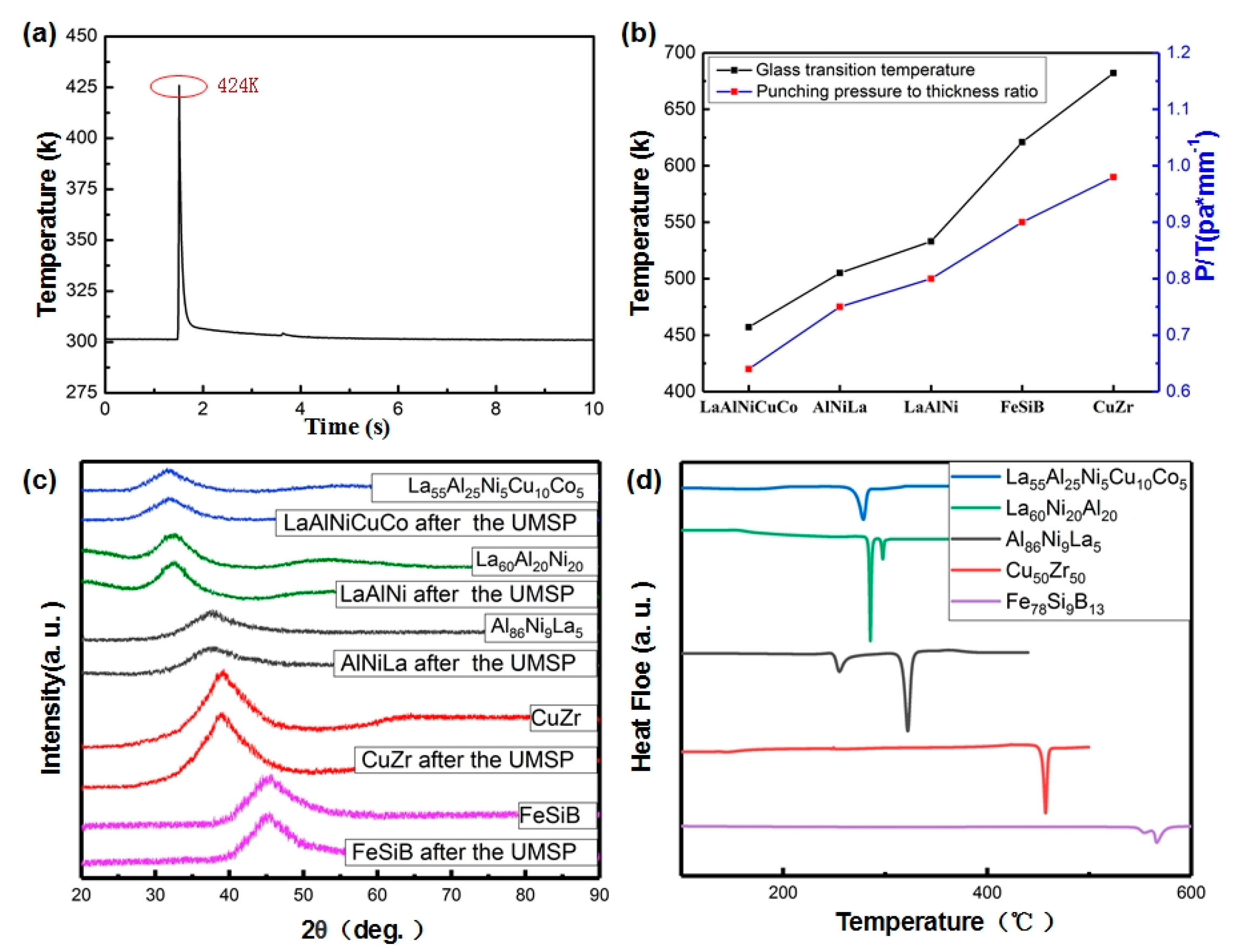
For an amorphous alloy, it is reasonable for the plastic powder to melt to form a flexible medium that can transmit vibration and pressure to the amorphous ribbon when the ultrasonic starts. Figure 3a shows the real-time temperature of the powder during ultrasonic loading. From the highlight in the figure, we can see that the maximum temperature was 424 K, which was lower than the glass transition temperature of the above-mentioned amorphous alloys. The amorphous alloy was only softened during the experiment, so EVA was not doped into the amorphous alloy ribbons, and the comparison of XRD images of samples before and after experiment also proves this point. Figure 3b shows the difficulty of forming several matrix amorphous alloys under shear punching of amorphous alloys under high frequency vibration. The thickness T of several amorphous materials in the experiment was different, so the pressure P was divided by the thickness T to indicate the difficulty of successful stamping. The larger the value, the more difficult it was to form. Figure 3c shows the XRD pattern of the amorphous alloy before and after the experiment. We found that the sample remained amorphous after the experiment. Figure 3d shows the DSC curve of amorphous alloys. It can be found from Figure 3 that the temperature of the powder sharply increased when ultrasonic waves occurred. However, the temperature was lower than the crystallization temperature of the amorphous alloy and the duration was very short, so the material was able to keep its original structure.
Figure 4a shows a schematic diagram of the principle of the experimental process. When ultrasonic loaded, the flexible medium can transmit not only pressure, but also high-frequency vibration of the ultrasonic wave to the amorphous alloy. Figure 4b,c shows that during the experiment, the central portion of the ribbon was suspended, and the high-frequency vibration energy dissipated through the elastic vibration of the amorphous alloy. For this reason, the elastic vibration was restricted from the corner contact of the mold to avoid energy loss, thereby activating the viscous flow of the amorphous strip at the corner of the mold, resulting in an amorphous low-stress punching.
3.3. Photographs of the Product after Shear Punching of Amorphous Alloys under High Frequency Vibration
To verify the applicability of the shear punching of amorphous alloys under high-frequency vibration in the plastic forming of amorphous alloys, several punching molds with two Chinese characters, “工” and “大”, and three capital letters, “B”, “M”, and “G”, representing amorphous alloys, were manufactured respectively. Pictures of the mold and the product of method are shown in Figure 5. The products obtained using this method matched almost perfectly to the mold both in size and in shape. In addition, there were slight differences in the “大” of the five samples in Figure 5. Due to the thickness difference of amorphous alloy ribbons with five substrates, there were differences in intrinsic properties and viscosities between amorphous alloys, and there were some differences between samples. We will continue to study the reasons for the differences and why they occur. It is worth noting that there was some special geometry, such as right angle and arc, which were well-formed here and are very difficult to create using a conventional method at room temperature. Compared with the thermoplastic forming method, the actual forming period of this shear punching of amorphous alloys under high-frequency vibration method is extremely short (50 ms) and does not need heating, which avoids the risk of oxidation and crystallization. Because of the excellent performance of the method on the above five amorphous alloys, it can be said that the method has wide applicability in the normal temperature plastic forming for amorphous alloys.
4. Conclusions
This paper presents a plastic forming method suitable for a variety of amorphous alloys. Different from the traditional method, shear punching of amorphous alloys under high-frequency vibration introduces ultrasonic assisted shaping innovatively. Moreover, the method is not limited by the punch profile, and more target products with various shapes can be manufactured. This method has the advantages of low cost, a short forming period, and good product quality in the process of forming amorphous alloys, making it an energy-saving and economic forming method with wide application prospects.
Author Contributions
J.M. and H.L. conduct the experiments, Y.Y., K.L. and H.L. designed the molds for forming, J.M., F.S., F.L. and H.L. wrote the manuscript.
Funding
The work was supported by the National Key Research and Development Program of China (Grant No. 2018YFA0703604), the National Science Foundation of China (Grant No. 51871157, 51971150), the Science and Technology Innovation Commission Shenzhen (Grants No. JCYJ20170412111216258).
Conflicts of Interest
The authors declare no conflict of interest.
References
- Klement, W.; Willens, R.H.; Duwez, P. Non-crystalline Structure in Solidified Gold-Silicon Alloys. Nature 1960, 187, 869–870. [Google Scholar] [CrossRef]
- Chen, H.S. Glassy metals. Rep. Prog. Phys. 1980, 43, 353. [Google Scholar] [CrossRef]
- Wang, W.H.; Dong, C.; Shek, C. Bulk metallic glasses. Mater. Sci. Eng. R Rep. 2004, 44, 45–89. [Google Scholar] [CrossRef]
- Schuh, C.A.; Hufnagel, T.C.; Ramamurty, U. Mechanical behavior of amorphous alloys. Acta Mater. 2007, 55, 4067–4109. [Google Scholar] [CrossRef]
- Zhang, J.J.; Estévez, D.; Zhao, Y.Y.; Huo, L.S.; Chang, C.T.; Wang, X.M.; Li, R.W. Flexural Strength and Weibull Analysis of Bulk Metallic Glasses. J. Mater. Sci. Technol. 2016, 32, 129–133. [Google Scholar] [CrossRef]
- Jan, S. Processing of bulk metallic glass. Adv. Mater. 2010, 22, 1566–1597. [Google Scholar]
- Ma, J.; Zhang, X.Y.; Wang, D.P.; Zhao, D.Q.; Ding, D.W.; Liu, K.; Wang, W.H. Superhydrophobic metallic glass surface with superior mechanical stability and corrosion resistance. Appl. Phys. Lett. 2014, 104, 387. [Google Scholar] [CrossRef]
- Pauly, S.; Gorantla, S.; Wang, G.; Kühn, U.; Eckert, J. Transformation-mediated ductility in CuZr-based bulk metallic glasses. Nat. Mater. 2010, 9, 473. [Google Scholar] [CrossRef]
- Liang, X.; Ma, J.; Wu, X.Y.; Xu, B.; Gong, F.; Lei, J.G.; Peng, T.J.; Cheng, R. Micro injection of metallic glasses parts under ultrasonic vibration. J. Mater. Sci. Technol. 2017, 33, 703–707. [Google Scholar] [CrossRef]
- Sung, T.J.; Jung, T.K.; Kim, M.S.; Yi, S. Processing and Properties of Al Based Amorphous/Crystalline Alloy Composites. Mater. Sci. Forum 2007, 544–545, 431–434. [Google Scholar] [CrossRef]
- Greer, A.L. Metallic glasses. Curr. Opin. Solid State Mater. Sci. 1995, 267, 1947–1953. [Google Scholar] [CrossRef] [PubMed]
- Pampillo, C.A. Flow and fracture in amorphous alloys. J. Mater. Sci. 1975, 10, 1194–1227. [Google Scholar] [CrossRef]
- Argon, A.S. Plastic deformation in metallic glasses. Acta Metall. 1979, 27, 47–58. [Google Scholar] [CrossRef]
- Seo, Y.H.; Chan, J.P.; Kim, B.H.; Lee, H.J.; Lee, N.K. Development of audio frequency vibration microforming system. Int. J. Precis. Eng. Manuf. 2012, 13, 789–794. [Google Scholar] [CrossRef]
- Pasierb, A.; Wojnar, A. An experimental investigation of deep drawing and drawing processes of thin - walled products with utilization of ultrasonic vibrations. J. Mater. Process. Technol. 1992, 34, 489–494. [Google Scholar] [CrossRef]
- Hung, J.C.; Lin, C.C. Investigations on the material property changes of ultrasonic-vibration assisted aluminum alloy upsetting. Mater. Des. 2013, 45, 412–420. [Google Scholar] [CrossRef]
- Lee, T.C.; Chan, L.C.; Wu, B.J. Straining behaviour in blanking process - fine blanking vs. conventional blanking. J. Mater. Process. Technol. 1995, 48, 105–111. [Google Scholar] [CrossRef]
- Kals, T.A.; Eckstein, R. Miniaturization in sheet metal working. J. Mater. Process. Technol. 2000, 103, 95–101. [Google Scholar] [CrossRef]
- Krautkramer, J.; Krautkramer, H. Ultrasonic Testing of Materials; Springer-Verlag: Berlin, Germany, 1977. [Google Scholar]
- Huang, Y.; Wang, D.; Fan, H.; Sun, J.; Shen, J.; Mi, J. Shear punching of a Ti-based bulk metallic glass. Mater. Sci. Eng. A 2013, 561, 220–225. [Google Scholar] [CrossRef]
- Takahashi, F.; Nishimura, T.; Suzuki, I.; Kudo, H. A Method of Blanking from Amorphous Alloy Foils Using Rubber Tool. CIRP Ann. Manuf. Technol. 1991, 40, 315–318. [Google Scholar] [CrossRef]
- Luo, F.; Sun, F.; Li, K.S.; Gong, F.; Liang, X.; Wu, X.Y.; Ma, J. Ultrasonic assisted micro-shear punching of amorphous alloy. Mater. Res. Lett. 2018, 6, 545–551. [Google Scholar] [CrossRef] [Green Version]
- Basu, J.; Nagendra, N.; Li, Y.; Ramamurty, U. Microstructure and mechanical properties of a partially crystallized La-based bulk metallic glass. Philos. Mag. 2003, 83, 1747–1760. [Google Scholar] [CrossRef]
- Nieh, T.G.; Wadsworth, J.; Liu, C.T.; Ohkubo, T.; Hirotsu, Y. Plasticity and structural instability in a bulk metallic glass deformed in the supercooled liquid region. Acta Mater. 2001, 49, 2887–2896. [Google Scholar] [CrossRef]
- Ma, J.; Liang, X.; Wu, X.Y.; Liu, Z.Y.; Gong, F. Sub-second thermoplastic forming of bulk metallic glasses by ultrasonic beating. Sci. Rep. 2015, 5, 17844. [Google Scholar] [CrossRef] [PubMed]
- Kundu, P.K.; Cohen, I.M. Fluid Mechanics, 4th ed.; Elsevier: London, UK, 2008. [Google Scholar]
- Ma, J.; Huo, L.S.; Zhao, D.Q.; Wang, W.H. Micro mold filling kinetics of metallic glasses in supercooled liquid state. J. Appl. Phys. 2013, 113, 104505. [Google Scholar] [CrossRef]
Figure 1.
Schematic diagram of shear punching of amorphous alloys under high-frequency vibrations.

Figure 2.
(a) Low-speed wire electric discharge machining mold cavity. (b,d) The partial magnified SEM image of the products. (c) SEM image of a product of amorphous alloy formed after shear punching of amorphous alloys under high-frequency vibrations. The proportions are all 1 mm.
Figure 2.
(a) Low-speed wire electric discharge machining mold cavity. (b,d) The partial magnified SEM image of the products. (c) SEM image of a product of amorphous alloy formed after shear punching of amorphous alloys under high-frequency vibrations. The proportions are all 1 mm.

Figure 3.
(a) The real-time temperature of plastic powder. (b) The difficulty of punching successfully of several matrix amorphous alloys in shear punching of amorphous alloys under high-frequency vibration (c) The X-ray diffraction (XRD) pattern of amorphous alloys before and after shear punching of amorphous alloys under high frequency vibration. (d) The differential scanning calorimetry (DSC) curve of amorphous alloys.

Figure 4.
(a) Schematic diagram of shear punching of amorphous alloys under high-frequency vibration principle. (b) Schematic diagram of soft zone separation of amorphous alloy strips in shear punching of amorphous alloys under high-frequency vibrations process. (c) Amorphous alloy strip soft zone seen from a top view during shear punching of amorphous alloys under high-frequency vibrations.

Figure 5.
The photographs of amorphous alloys after shear punching of amorphous alloys under high-frequency vibration.
Figure 5.
The photographs of amorphous alloys after shear punching of amorphous alloys under high-frequency vibration.


Table 1.
The glass transition temperature (Tg) and crystallization temperature (Tx) of amorphous alloys.
Table 1.
The glass transition temperature (Tg) and crystallization temperature (Tx) of amorphous alloys.
| Materials | Tg (k) | Tx (k) | Thickness (μm) |
|---|---|---|---|
| La55Al25Ni5Cu10Co5 | 457 | 538 | 80 ± 3 |
| Al86Ni9La5 | 505 | 520 | 60 ± 3 |
| La60Al20Ni20 | 533 | 554 | 50 ± 3 |
| Fe78Si9B13 | 621 | 811 | 30 ± 3 |
| Cu50Zr50 | 682 | 725 | 50 ± 3 |
© 2019 by the authors. Licensee MDPI, Basel, Switzerland. This article is an open access article distributed under the terms and conditions of the Creative Commons Attribution (CC BY) license (http://creativecommons.org/licenses/by/4.0/).
Share and Cite
MDPI and ACS Style
Li, H.; Yan, Y.; Sun, F.; Li, K.; Luo, F.; Ma, J. Shear Punching of Amorphous Alloys under High-Frequency Vibrations. Metals 2019, 9, 1158. https://doi.org/10.3390/met9111158
AMA Style
Li H, Yan Y, Sun F, Li K, Luo F, Ma J. Shear Punching of Amorphous Alloys under High-Frequency Vibrations. Metals. 2019; 9(11):1158. https://doi.org/10.3390/met9111158
Chicago/Turabian StyleLi, Hongzhen, Yuqiang Yan, Fei Sun, Kangsen Li, Feng Luo, and Jiang Ma. 2019. "Shear Punching of Amorphous Alloys under High-Frequency Vibrations" Metals 9, no. 11: 1158. https://doi.org/10.3390/met9111158
Note that from the first issue of 2016, this journal uses article numbers instead of page numbers. See further details here.