Article

A Comparative Investigation on Conventional and Stationary Shoulder Friction Stir Welding of Al-7075 Butt-Lap Structure

1
School of Mechanical Engineering and Automation, Northeastern University, Shenyang 110819, China
2
School of Materials Science and Engineering, Taiyuan University of Science and Technology, Taiyuan 030024, China
3
School of Materials Science and Engineering, Northeastern University, Shenyang 110819, China
*
Authors to whom correspondence should be addressed.
Metals 2019, 9(12), 1264; https://doi.org/10.3390/met9121264
Submission received: 3 November 2019 / Revised: 21 November 2019 / Accepted: 22 November 2019 / Published: 26 November 2019

Abstract

:
Both conventional friction stir welding (C-FSW) and stationary shoulder friction stir welding (S-FSW) were employed to join the Al-7075 butt-lap structure, then the microstructural evolution and mechanical characterization of all FSW joints were systematically studied. The C-FSW joint exhibited a rough surface with flashes and arc corrugations, while the surface of the S-FSW joint became smooth. Moreover, for the S-FSW joint, the shoulder-affected zone got eliminated and the material flow mode during FSW was changed owning to the application of stationary shoulder. Furthermore, in comparison to C-FSW, the lower welding heat input of S-FSW decreased the average grain size in the nugget zone and inhibited the coarsening of strengthening precipitates in the heat-affected zone, elevating the overall hardness for the S-FSW joint. In addition, the tensile strength of the S-FSW joint became higher compared to the C-FSW joint, and all the FSW joints failed inside the nugget zone attributing to the existence of hook defect. The sharp-angled hook defect deteriorated the plasticity of the C-FSW joint further, which was only 70% that of the S-FSW joint.

1. Introduction

As a new solid-state joining/welding technology, friction stir welding (FSW) has proved to be very suitable for joining aluminum alloys [1], moreover, after decades of development, some variant FSW techniques (such as stationary shoulder FSW, pinless FSW, and bobbin tool FSW) have also been proposed and applied for the industry [2,3,4]. In conventional FSW (C-FSW), a nonconsumable rotational tool plunges into the workpieces and advances along the welding direction, creating the C-FSW joint [5]. And it is believed that the rotational shoulder generates more frictional heat at the top of workpieces, resulting in both the thermal and microstructural gradients across the thickness of workpieces [6]. Besides, the rotational shoulder gives rise to the formation of arc corrugations on the surface of workpieces, influencing the fatigue property of the C-FSW joint [7].
Recently, stationary shoulder FSW (S-FSW) was proposed by The Welding Institute (TWI) to solve the above problems [8]. The tool of S-FSW consists of a nonrotational shoulder (namely stationary shoulder) and a rotational pin, almost no frictional heat input is produced by the stationary shoulder, and meanwhile, the frictional heat input of rotational pin is nearly linear, as a result, the gradients in the temperature and microstructures across the thickness can be significantly reduced [9]. Furthermore, the smooth joint surface can also be obtained due to the scraping effect of the stationary shoulder [10].
Up to now, a number of researchers have conducted S-FSW on aluminum alloys and investigated the microstructural and mechanical characterizations of the S-FSW joint. For instance, Ahmed et al. [11] butt-joined Al-6082 using S-FSW and then analyzed the crystallographic texture of the nugget zone (NZ), and they reported that the shoulder-affected zone (SAZ) disappeared and the whole NZ was mainly occupied by the shear texture arisen from the pin. Wu et al. [12] stated that, for the butt joint of Al-7075, the welding heat input of C-FSW was about 30% higher in comparison to S-FSW, moreover, the heat-affected zone (HAZ) in the S-FSW joint was narrowed. Li et al. [13] friction stir lap welded Al-2024 with a stationary shoulder tool, and found that the application of stationary shoulder not only eliminated the defects in the NZ but also enhanced the lap shear failure strength of the lap joint. Ji et al. [14] also joined the lap structure of Al-2024 using conventional and stationary shoulder tools, and observed that the distortion of lap joint produced by the stationary shoulder tool was much smaller.
As mentioned above, both the butt and lap structure of aluminum alloys could be successfully joined by S-FSW, furthermore, the performances (such as the welding formability, strength, and microstructures) of the S-FSW joint were better than those of the C-FSW joint, and thus it becomes necessary to broaden the application range of S-FSW. For the train industry, C-FSW is mainly employed to join the butt-lap structure, and S-FSW may be also suitable for joining this welding structure. However, to our knowledge, the welding behavior of S-FSW on the butt-lap structure has not been studied so far. Therefore, the Al-7050 butt-lap structure was welded by C-FSW and S-FSW in the present work, aiming at comparing the different effects of above two techniques on the mechanical properties and microstructures of the butt-lap structure.

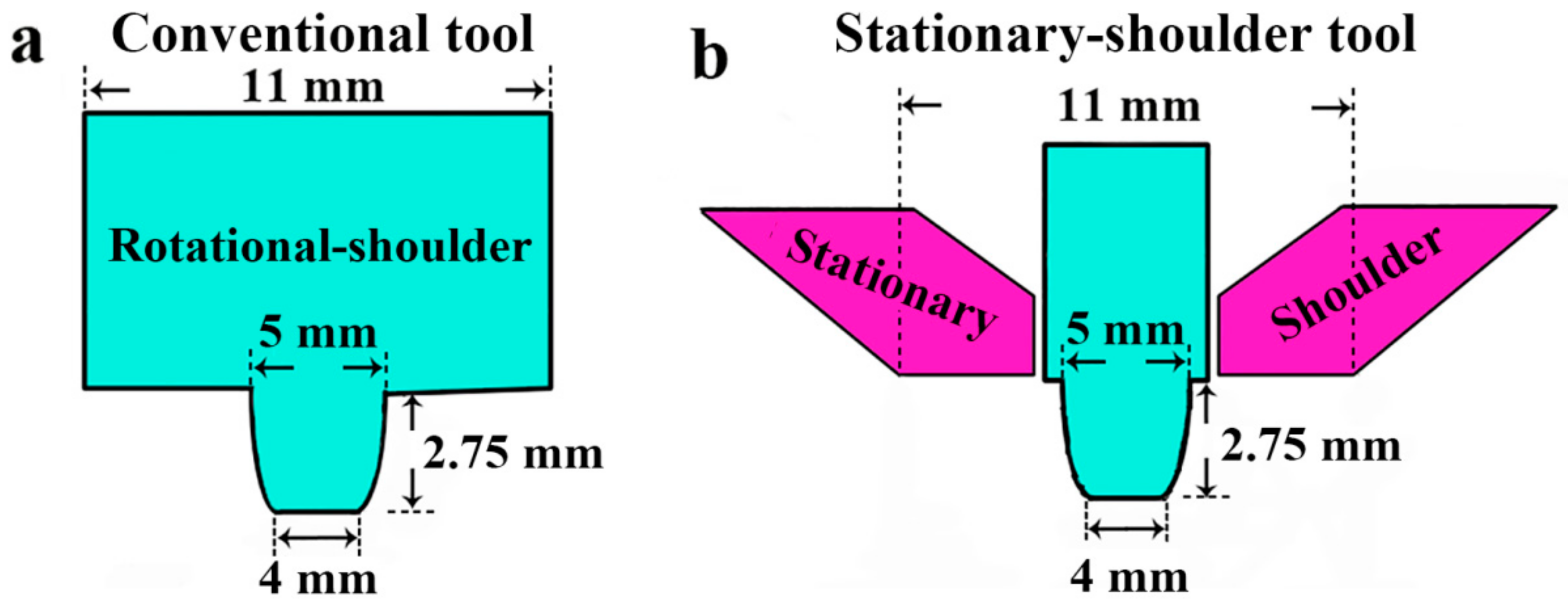
2. Materials and Methods

Rolled Al-7075 sheet in T651 temper (namely artificial aging) was chosen as the base metal (BM), moreover, Table 1 listed its nominal chemical compositions. As shown in Figure 1, the dimensions of conventional and stationary shoulder tools are the same: a flat shoulder (diameter: 11 mm) combined with a tapered pin (length: 2.75 mm, pin-root diameter: 5 mm, pin-root diameter: 4 mm). C-FSW/S-FSW was conducted with 1200 rpm rotational speed and 200 mm/min welding speed, besides, the tool tilt was 2° and the tool plunge depth was 0.25 mm. The schematic diagram of butt-lap structure is shown in Figure 2a, in order to limit the distortion of workpieces during FSW, the thin sheet (3 mm in thickness) was placed at retreating side (RS) and the thick one (5 mm in thickness) was at advancing side (AS).
The microstructures of the FSW joints were observed by the optical microscopy (OM, Olympus-DSX, Olympus, Tokyo, Japan), electron backscattered diffraction (EBSD, FEI Quanta 600, FEI, Portland, OR, USA), and transmission electron microscopy (TEM, Technai G220, FEI, Portland, OR, USA). The samples of OM were processed by mechanical grinding and polishing and then etching by Keller’s reagent. The samples for EBSD analysis were prepared by mechanical grinding and electron polishing (10% perchloric acid and 90% ethanol), furthermore, 0.14 μm was selected as the EBSD scanning step. The twinjet electron polishing was conducted to produce the TEM samples (temperature: −30 °C; voltage: 18 V), the electron polishing solution was composed of 30% nitric acid and 70% methanol. In addition, the differential scanning calorimeter (DSC, Setaram DSC-131, Setaram, Lyons, France) was applied for examining the precipitates evolution, and the samples of DSC (weight: 25 mg, diameter: 4.5 mm) were heated from the ambient temperature (25 °C) to 500 °C using a 10 °C /min heating rate.
The profiles of hardness were measured along the cross-section of the FSW joints (1.5 mm below the top surface) with a FM-700 hardness tester, the distance between neighboring measured points was 0.5 mm, and the test load and the dwelling time was 50 gf and 5 s, respectively. The schematic diagram of the hardness measurement is shown in Figure 3. Three hardness specimens for each FSW joint were prepared and the average values were used for analysis. Room temperature tensile test was carried out using a universal testing machine, and the strain rate for tensile test is 1 × 10⁻³ s−1. The tensile specimens (gauge length: 25 mm, gauge width: 4 mm) were processed perpendicular to the welding direction. Three tensile specimens for each joint were tested to obtain the average values. After tensile test, the fracture morphologies of tensile specimens were analyzed with the scanning electron microscopy (SEM, FEI-Quanta 600, FEI, Portland, OR, USA). It should be noted that, in order to avoid the post-welded natural aging, both the hardness and the room temperature tensile test were conducted within two weeks after FSW.

3. Results

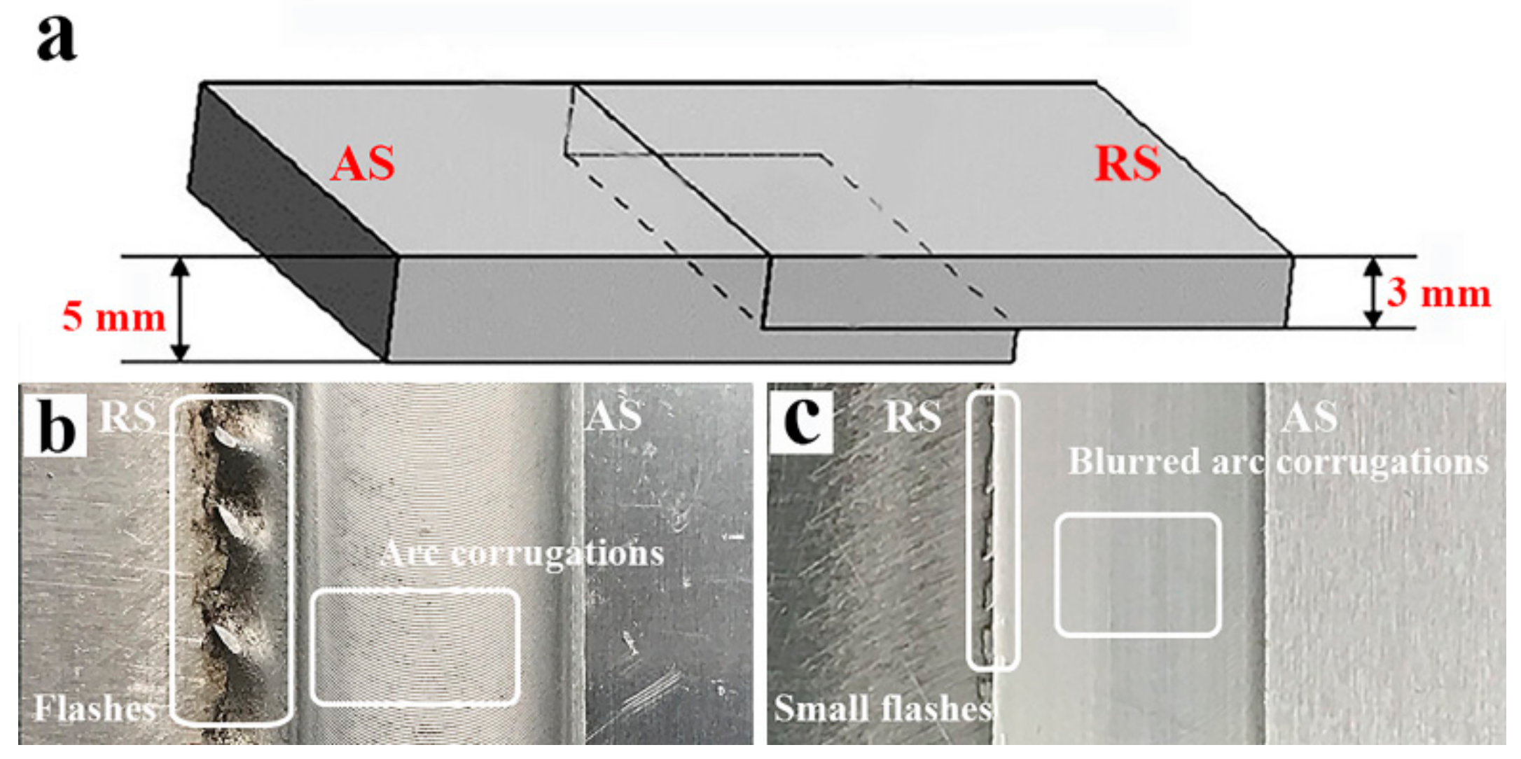
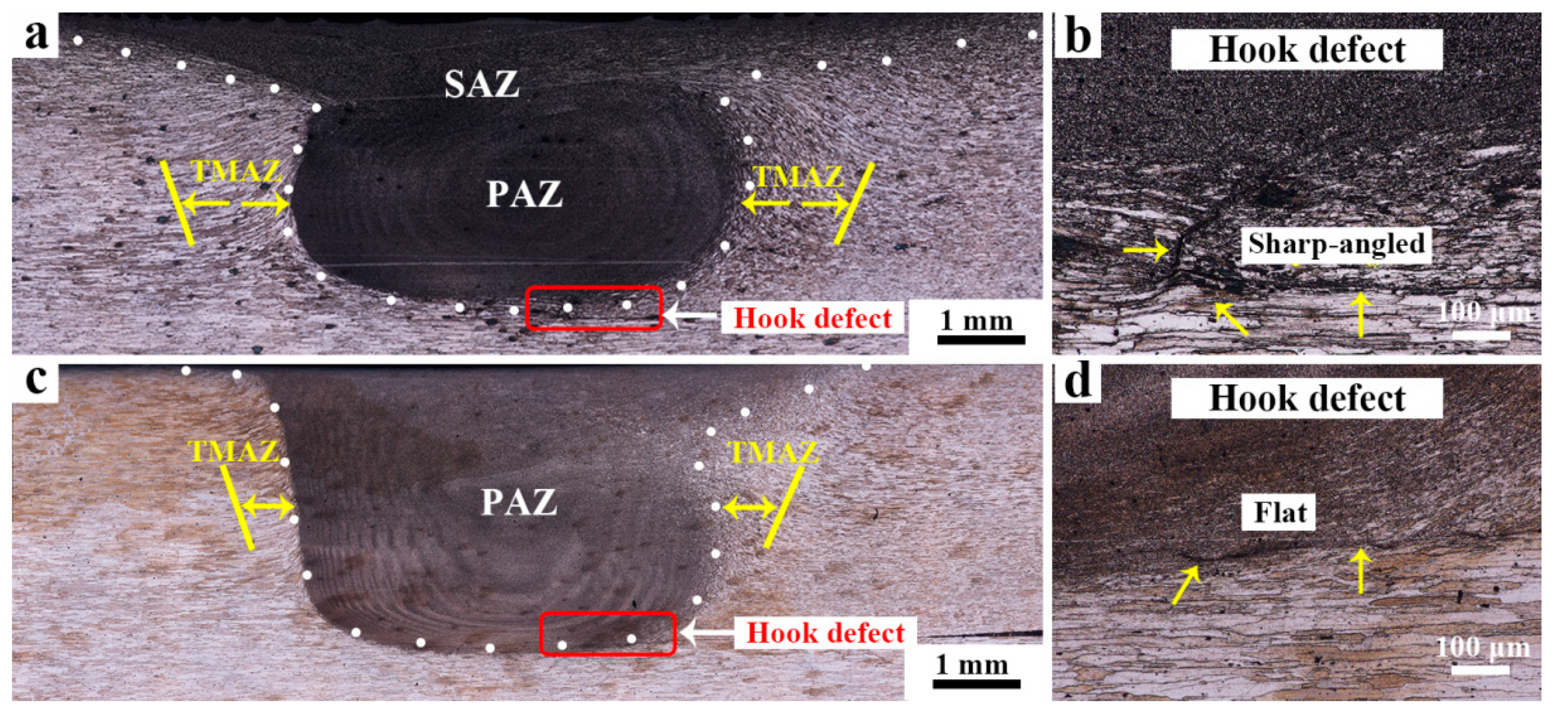
3.1. The Macrostructures of FSW Joints

The top surface topographies of the C-FSW/S-FSW joints are shown in Figure 2; large flashes generate at RS and obvious arc corrugations can be detected on the top surface of NZ (Figure 2b). By contrast, the surface of S-FSW is relatively smooth (Figure 2c), the arc corrugations become blur and only very small flashes appear at RS. Due to no rotation, the stationary shoulder slides over the surface of the S-FSW joint, which is beneficial for scraping the arc corrugations. And meanwhile, the stationary shoulder prevents the plastic materials escaping from the NZ, restraining the formation of flashes [15]. As a result, the surface roughness of the S-FSW joint significantly decreases in comparison to that of the C-FSW joint.
The cross-sections of the C-FSW/S-FSW joints are shown in Figure 4. As to the C-FSW joint (Figure 4a), the NZ is comprised of the shoulder-affected zone (SAZ) and pin-affected zone (PAZ) [16], moreover, a wide thermo-mechanical-affected zone (TMAZ) can be observed. Similar to the results of [11,12,13,14], the application of stationary shoulder contributes to the elimination of SAZ (Figure 4c), and the width of TMAZ is also narrowed. In addition, for both FSW joints, the hook defect can be found in the bottom of NZ, which originates from the lap intersection at RS and then extends into the NZ. The features of the hook defect are different: For the C-FSW joint, the hook defect is sharp-angled (Figure 4b), which firstly flows upward into the NZ and then bends toward the TMAZ. By contrast, the morphology of the hook becomes flat as to the S-FSW joint (Figure 4d), where the upward bending of the hook defect is slight.
During welding, the welding heat input softens the materials and the rotational tool gives rise to the material flow [17]. The material flow modes of C-FSW and S-FSW in the present work can be illustrated by Figure 5. As to C-FSW (Figure 5a), the material flow is divided into two parts: (I) The materials in the SAZ are firstly rotated by the rotational shoulder and then flow downward around the pin, extruding the materials in the PAZ; (II) driven by the extruding force from both the pin and the SAZ, the materials in the PAZ are transferred downward and concentrates at the bottom of NZ, as the welding processing goes on, the amount of concentrated materials becomes larger, presses and forces the materials of lower sheet to flow. Compared with the rigid back-plate, the adjacent TMAZ is much softer, and thus the materials of lower sheet tend to flow upward and then bend toward the TMAZ, resulting in the formation of the sharp-angled hook defect. As to S-FSW (Figure 5b), both the heat input and driving force provided by the stationary shoulder are insufficient, thus the amount of softened materials in the SAZ decreases and the material flow of SAZ is also restrained. As a result, the extruding force from SAZ reduces significantly, and the reduced extruding force cannot transfer enough materials of PAZ downward, suppressing the upward bending of the hook defect. Furthermore, the stationary shoulder also provides a very huge vertical forging force on the materials [14], which is beneficial for straightening the hook defect. Consequently, the shape of the hook defect in the NZ is changed from sharp-angled to flat by using S-FSW.

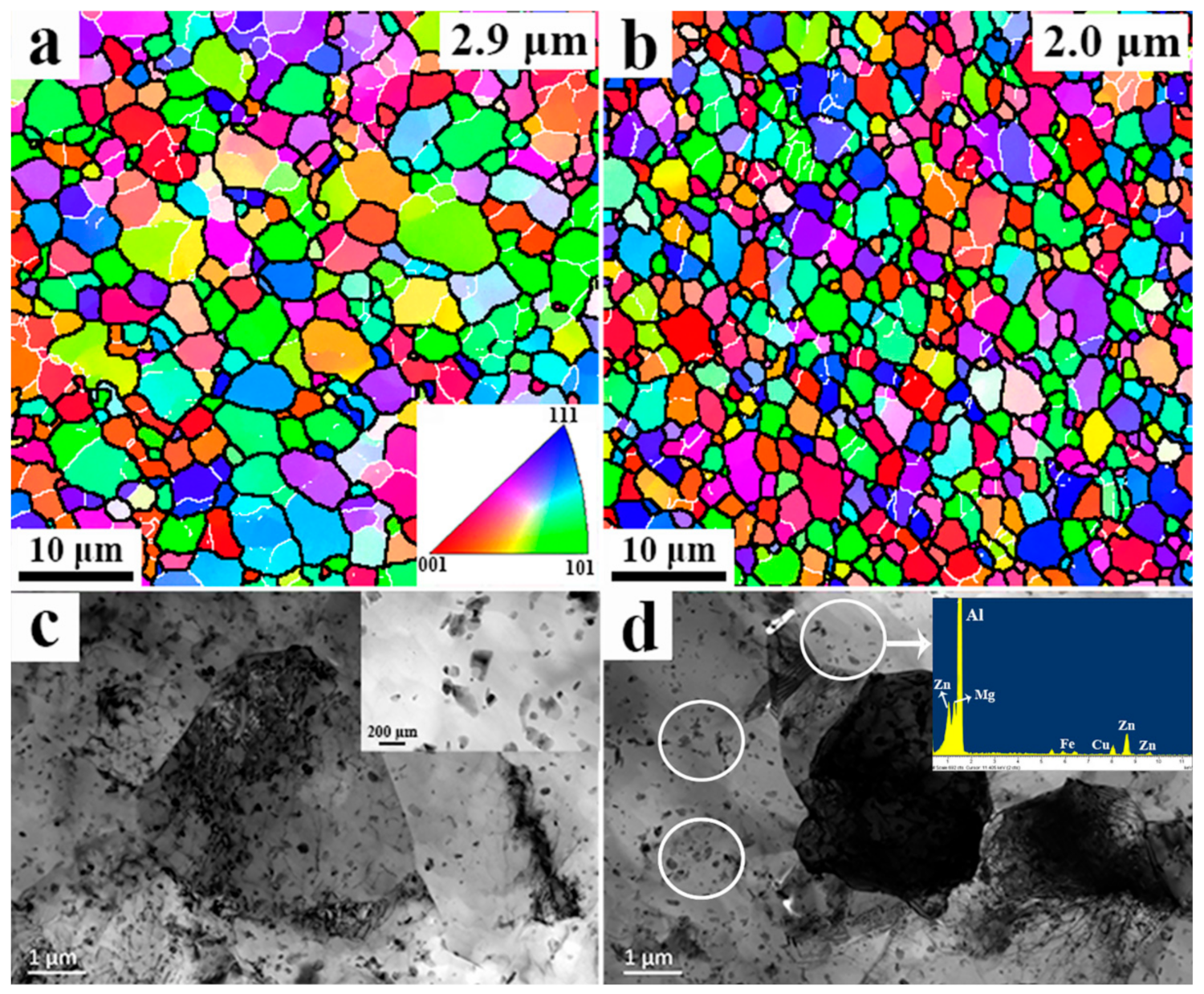
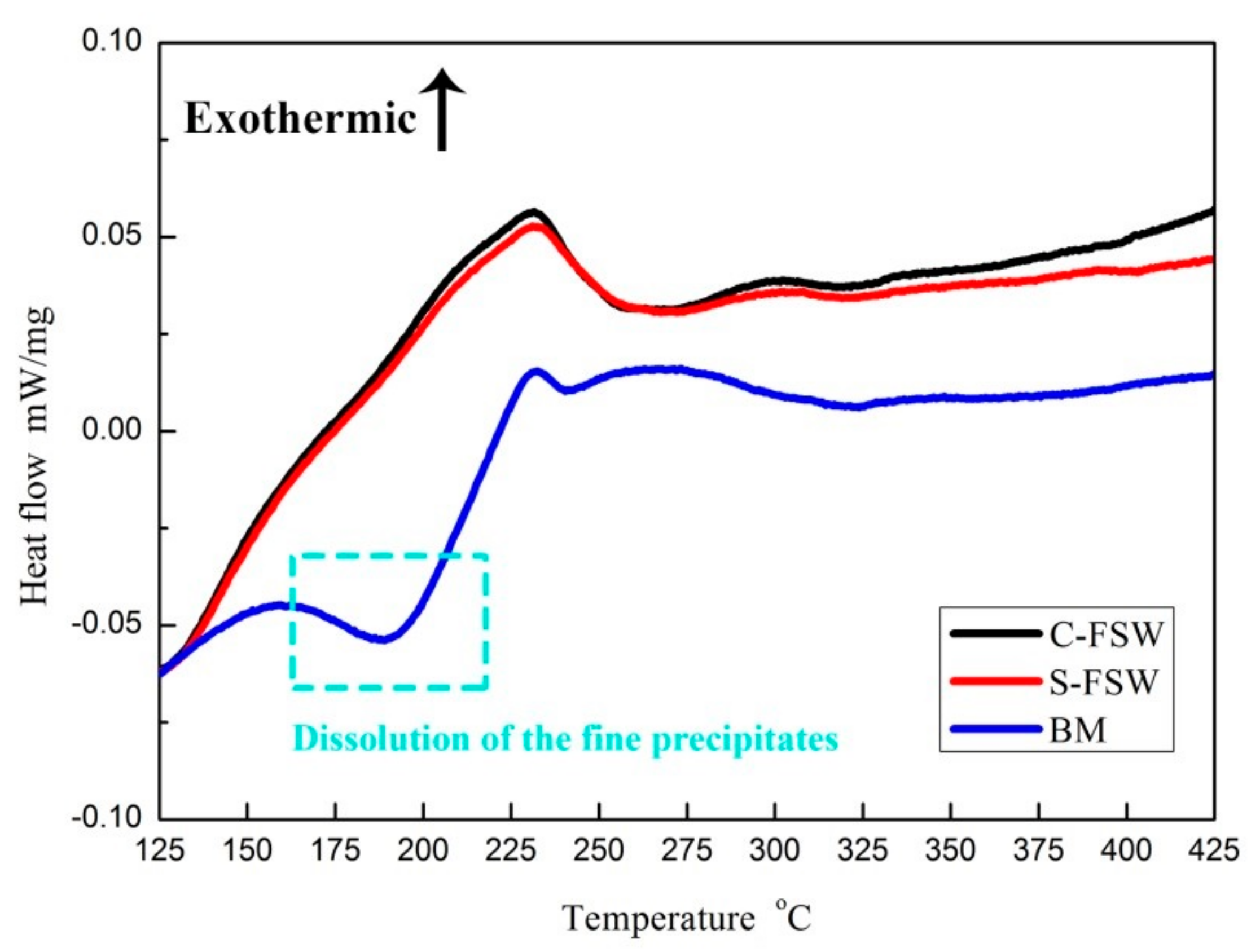
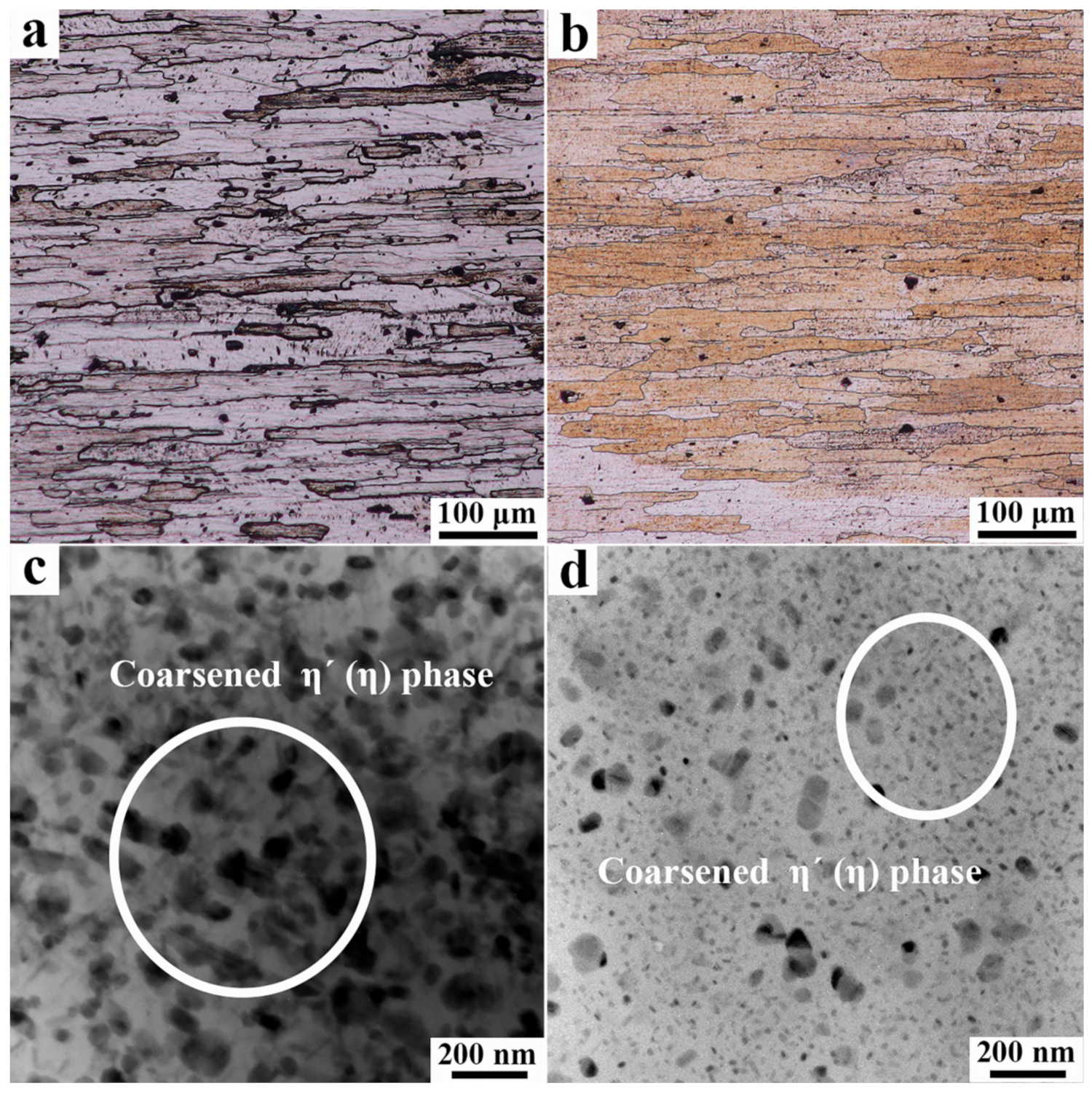
3.2. The Microstructures of FSW Foints

The BM is characterized by the elongated grains on account of the rolling process (Figure 6a), the average width and length of grains are ~20 and ~150 μm, respectively. Furthermore, numerous fine strengthening precipitates on the order of 2–5 nm can be found in the Al-matrix (Figure 6b), which are regarded as the η (η’)-MgZn2 phase. The precipitates sequence in the Al-7075 alloy is solid solution→GP zones→η (η’)-MgZn2, the fine η (η’) forms during the artificial aging and plays the key role in strengthening the BM. The η′-phase was regarded as slight strained version in comparison to the η-phase [18], and thus η- and η′-phase will not be distinguished here.
During FSW, the materials in the NZ undergo intense deformation and welding thermal cycle, resulting in the occurrence of dynamic recrystallization (DRX). In the NZ, fine and equiaxed recrystallized grains take the place of initial elongated grains, and no obvious textures can be detected (Figure 7a,b). The average grain size of NZ for the C-FSW joint is 2.9 μm, and it decreases to about 2 μm for the S-FSW joint. It is known that the size of DRX grains increases as the welding heat input elevates [19], the welding heat input of S-FSW is lower than that of C-FSW [12], contributing to the finer grains of the S-FSW joint. Except for the grain refinement, the density of dislocations is relatively low due to the DRX (Figure 7c,d), and the initial fine η (η’) dissolves into the matrix because of FSW heating [20]. Only coarse Fe–Cu-rich particles remain in the NZ, and these coarse particles are mainly the constitute phase Al7Cu2Fe [21,22], which owns high dissolution point.
Figure 8 shows the results of DSC analysis: An endothermic peak is found around 200 °C in the DSC curve of BM, while no endothermic peak can be found in the DSC curves of C-FSW and S-FSW joints. In general, the endothermic peaks of the DSC curve indicate the occurrence of dissolution reaction and the exothermic peaks indicate the occurrence of precipitation reaction. As to the BM, the initial precipitates are fine η (η’), which owns relatively low dissolution reaction point (160–300 °C [23]). During DSC heating, these fine precipitates dissolve and results in an endothermic peak. By contrast, the heat input of FSW leads to the dissolution of precipitates, and thus the endothermic peak becomes smaller or less obvious for the FSW samples. In the present work, the difference in the DSC curves between C-FSW and S-FSW samples is slight, which indicates that the heat input provided by either C-FSW or S-FSW is sufficient enough for dissolving whole the fine η (η’) in the NZ.
The grain morphologies of TMAZ are different at AS and RS, the TMAZ at AS is featured by the elongated and bended grains (Figure 9a,c), while it is dominated by the coarse and equiaxed grains in the TMAZ at RS (Figure 9b,d). The above differences might be caused by the asymmetric welding temperature distribution and material flow between AS and RS [24]. Furthermore, compared with C-FSW, the lower welding heat input of S-FSW results in finer grains in the TMAZ.
Different from the NZ and TMAZ, the HAZ merely undergoes thermal cycle during FSW, and thus the grains of HAZ keep elongated while a bit coarser in comparison to BM (as shown in Figure 10a,b). Apart from the grain growth, significant coarsening of η (η’) can also be found in the HAZ, the mean size of η (η’) increases to ~75 nm for the C-FSW joint (Figure 10c) and ~20 nm for the S-FSW joint (Figure 10d). The welding temperature of HAZ is not high enough for dissolving the strengthening precipitates [21,25], and the initial fine η (η’) gets coarsened owing to the FSW heating. However, the final morphology of η (η’) in the HAZ mainly depends on the cooling rate during FSW, and increasing the cooling rate is beneficial for restraining the coarsening of η (η’) [23]. In comparison to C-FSW, the lower heat input of S-FSW is beneficial for increasing the cooling rate [26], and meanwhile, the relatively cold stationary shoulder is thought to heat sink [27], which also enhances the cooling rate of S-FSW. As a result, the faster cooling rate shortens the time for the coarsening of η (η’), leading to finer microstructures of HAZ for the S-FSW joint.

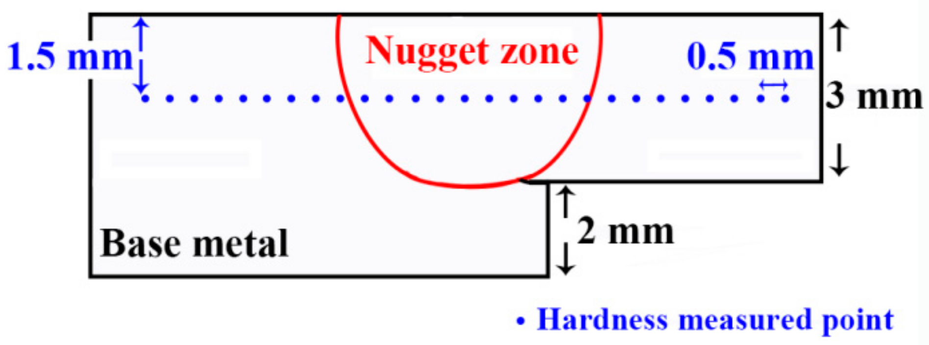
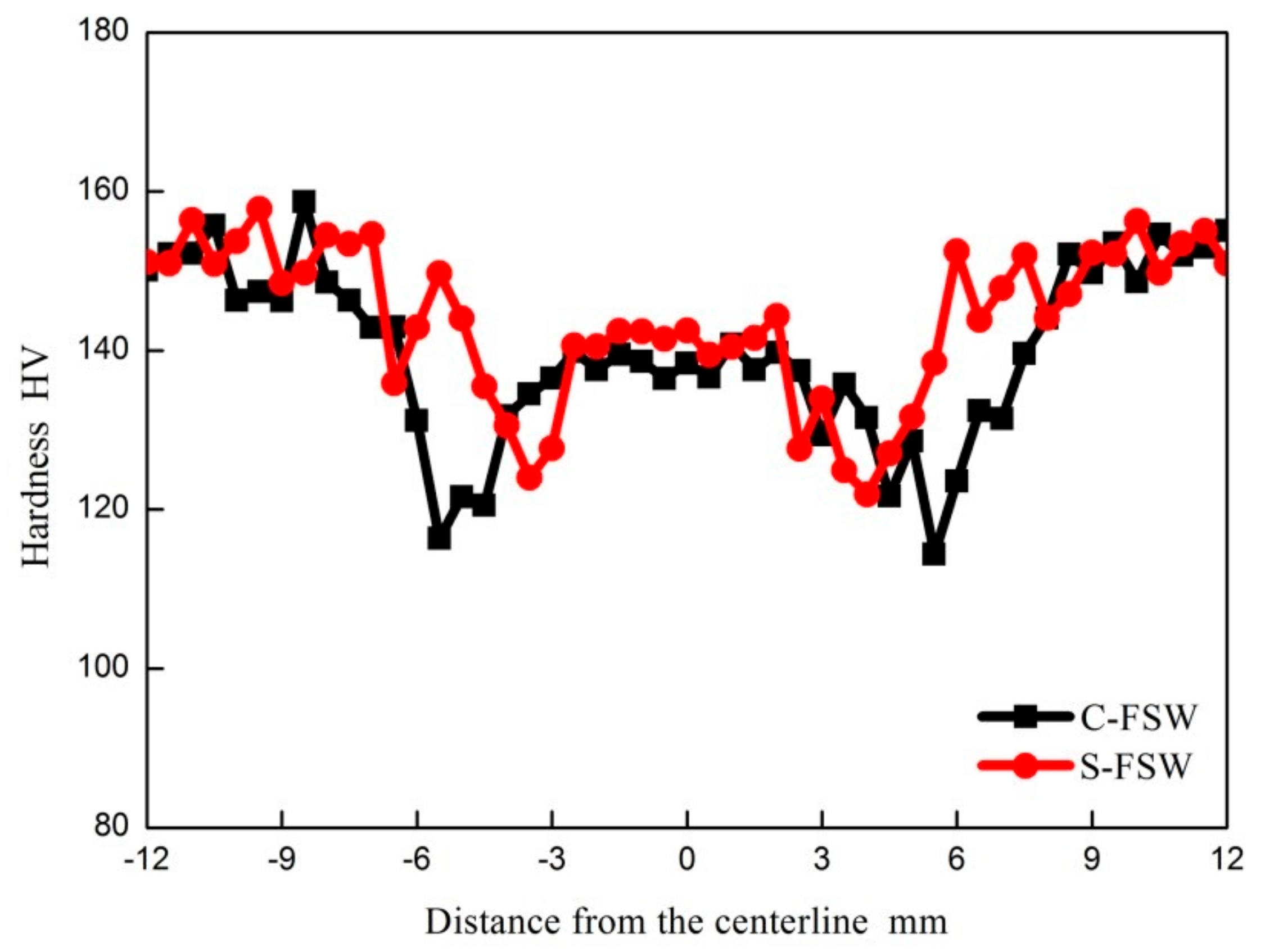
3.3. The Mechanical Characterizations of FSW Joints

Figure 11 exhibits the profiles of hardness for the C-FSW/S-FSW joints, both hardness curves are “W” shape. Compared with BM, the dissolution of fine η (η’) significantly decreases the precipitation strengthening [28], reducing the hardness of NZ. As to the C-FSW joint, the average hardness in the NZ is 137 HV, which is 15 HV lower than BM. In comparison, the NZ of the S-FSW joint gets strengthened because of the decreased grain size, and the average hardness is increased to 142 HV. The softening in the HAZ/TMAZ is mainly caused by the coarsening of strengthening precipitates [29], and the HAZ becomes the lowest hardness zone (LHZ) in this work. The coarsened η (η’) could not strengthen the HAZ effectively, and therefore, the average hardness in the HAZ is merely 115 HV for the C-FSW joint. By contrast, the faster cooling rate of S-FSW strengthens the HAZ, the average hardness is increased to 124 HV. In a word, compared with the C-FSW joint, the overall hardness for the S-FSW joint is higher, moreover, the width of the soft region in the S-FSW joint becomes narrower.
Similar to the results of hardness, the tensile properties of the S-FSW joint are enhanced compared with the C-FSW joint (Table 2). The yield strength increases from 264 MPa for the C-FSW joint to 302 MPa for the S-FSW joint, and meanwhile, a 40 MPa increase in the ultimate tensile strength can be also obtained by utilizing S-FSW. And the joint strength efficiency of C-FSW and S-FSW are 60% and 80%, respectively.
Generally speaking, the fracture tends to occur in the LHZ [30], however, all the FSW joints fail inside the NZ at this time. Figure 12 shows the typical failure morphologies of FSW joints, and it seems that the unusual failure is related to the hook defect. The crack propagates along the hook defect into the NZ, and hence the failure feature of the FSW joint is similar to the shape of the hook defect (Figure 12a): sharp-angled feature for the C-FSW joint and flat feature for the S-FSW joint. The shape of the hook defect can influence the effective sheet thickness (EST), which refers to the minimum distance from the hook tip to the top surface of the upper sheet [31]. As to the C-FSW joint, the EST is small due to the upward bending of the hook defect, decreasing the tensile strength of the joint. By contrast, the flat hook defect increases the EST, enhancing the tensile strength of the S-FSW joint. Furthermore, the morphology of the hook defect also affects the plasticity of the joint: both the tear-ridges and dimples can be detected in the fracture surface of the C-FSW joint, (Figure 12b), thus the mixed fracture occurs during the tensile test [32]. In comparison, the fracture surface of the S-FSW joint is characterized by numerous fine dimples, which indicates that the mode of failure is ductile [33]. In short, compared with the flat hook defect, the sharp-angled hook defect is easy to cause the stress concentration, changing the mode of failure and deteriorating the total elongation of the FSW joint (8%/5% for the S-FSW/C-FSW joints).

4. Conclusions

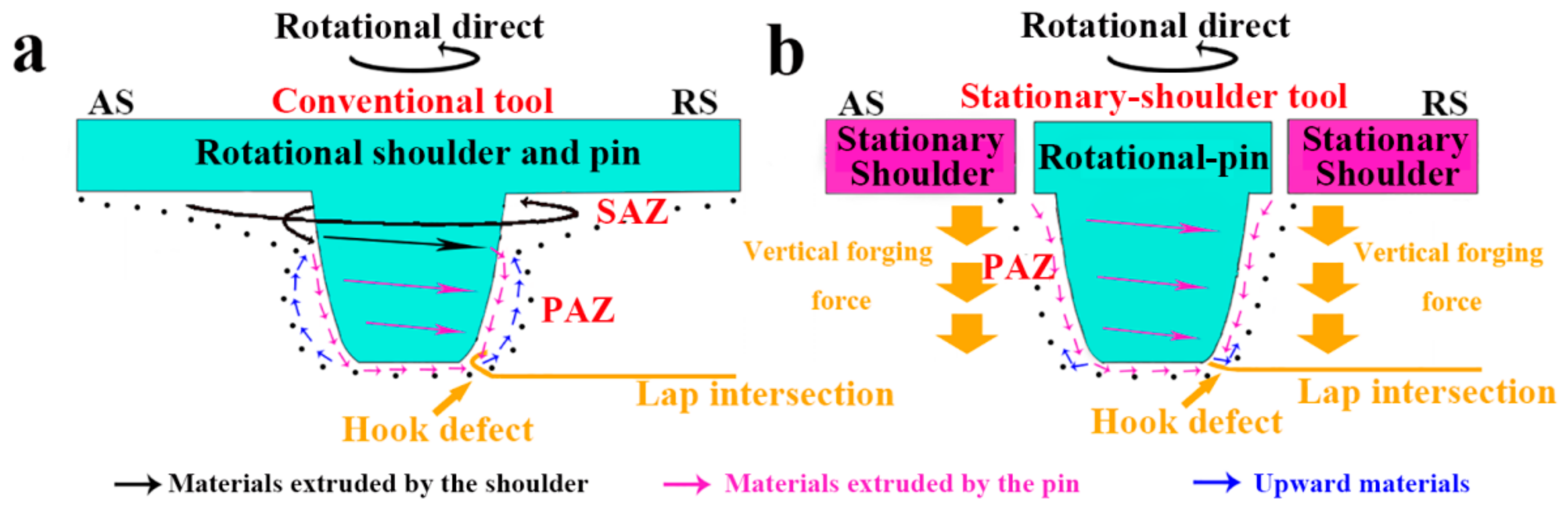
  • The surface of the joint became smooth by using S-FSW, and moreover, the SAZ of the S-FSW joint was eliminated. The material flow mode was changed by the application of stationary shoulder, resulting in the formation of the flat hook defect.
  • Compared with C-FSW, the grain size in the NZ decreased and the coarsening of strengthening precipitates in the HAZ was inhibited owning to the lower welding heat input of S-FSW. And both the hardness and tensile strength of the S-FSW joint were enhanced in comparison to the C-FSW joint due to the finer microstructures.
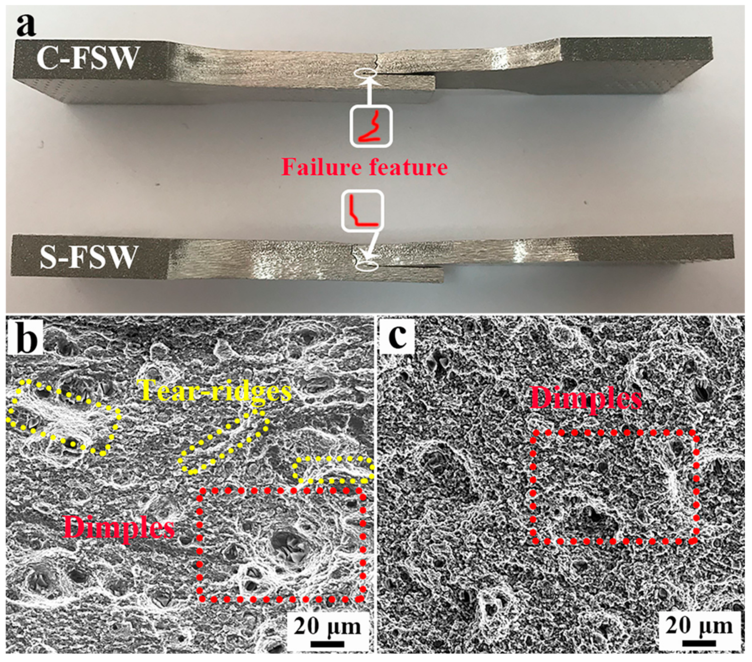
  • All the FSW joints got fractured inside the NZ because of hook defect, and the plasticity of the FSW joints was controlled by the shape of the hook defect. In comparison to the flat hook defect of the S-FSW joint, the sharp-angled hook defect decreased the total elongation of the C-FSW joint further.

Author Contributions

Conceptualization, Y.C.; methodology, Y.C. and H.L.; software, Y.C., H.D., and F.Z.; formal analysis, Y.C., X.W. and F.Z.; investigation, Y.C.; resources, Y.C.; data curation, Y.C.; writing—original draft preparation, Y.C.; writing—review and editing, H.L., H.D., X.W. and F.Z.; project administration, Y.C.; funding acquisition, Y.C.

Funding

This research was funded by the Nature Science Foundation of Liaoning Province, No. 20180550058 and the Fundamental Research Funds for the Central Universities of China, No. N180303029.

Conflicts of Interest

The authors declare no conflict of interest.

References

  1. Mishra, R.S.; Ma, Z.Y. Friction stir welding and processing. Mater. Sci. Eng. R 2005, 50, 1–78. [Google Scholar] [CrossRef]
  2. Ji, S.D.; Meng, X.C.; Ma, L.; Gao, S.S. Vertical compensation friction stir welding assisted by external stationary shoulder. Mater. Des. 2015, 68, 72–79. [Google Scholar] [CrossRef]
  3. Ni, Y.; Fu, L.; Chen, H.Y. Effects of travel speed on mechanical properties of AA7075-T6 ultra-thin sheet joints fabricated by high rotational speed micro pinless friction stir welding. J. Mater. Process. Technol. 2019, 265, 63–70. [Google Scholar] [CrossRef]
  4. Wang, F.F.; Li, W.Y.; Shen, J.; Hu, S.Y.; Santos, J.F.D. Effect of tool rotational speed on the microstructure and mechanical properties of bobbin tool friction stir welding of Al-Li alloy. Mater. Des. 2015, 86, 933–940. [Google Scholar] [CrossRef]
  5. Chen, Y.; Ding, H.; Cai, Z.H.; Zhao, J.W.; Li, J.Z. Microstructural and mechanical characterization of a dissimilar friction stir-welded AA5083-AA7B04 butt joint. J. Mater. Eng. Perform. 2017, 26, 530–539. [Google Scholar] [CrossRef]
  6. Liu, H.J.; Li, J.Q.; Duan, W.J. Friction stir welding characteristics of 2219-T6 aluminum alloy assisted by external non-rotational shoulder. Int. J. Adv. Manuf. Technol. 2013, 64, 1685–1694. [Google Scholar] [CrossRef]
  7. Li, D.X.; Yang, X.Q.; Cui, L.; He, F.Z.; Shen, H. Effect of welding parameters on microstructure and mechanical properties of AA6061-T6 butt welded joints by stationary shoulder friction stir welding. Mater. Des. 2014, 64, 251–260. [Google Scholar] [CrossRef]
  8. Ji, S.D.; Meng, X.C.; Liu, J.G.; Zhang, L.G.; Gao, S.S. Formation and mechanical properties of stationary shoulder friction stir welded 6005A-T6 aluminum alloy. Mater. Des. 2014, 62, 113–117. [Google Scholar] [CrossRef]
  9. Wen, Q.; Li, W.Y.; Wang, W.B.; Wang, F.F.; Gao, Y.J.; Patel, V. Experimental and numerical investigations of bonding inferface behavior in stationary shoulder friction stir lap welding. J. Mater. Sci. Technol. 2019, 35, 192–200. [Google Scholar] [CrossRef]
  10. Ji, S.D.; Li, Z.W.; Zhang, L.G.; Zhou, Z.L.; Chai, P. Effect of lap configuration on magnesium to aluminum friction stir lap welding assisted by external stationary shoulder. Mater. Des. 2016, 103, 160–170. [Google Scholar] [CrossRef]
  11. Ahmed, M.M.Z.; Wynne, B.P.; Rainforth, W.M.; Threadgill, P.L. Through-thickness crystallographic texture of stationary shoulder friction stir welded aluminum. Scr. Mater. 2011, 64, 45–48. [Google Scholar] [CrossRef]
  12. Wu, H.; Chen, Y.C.; Strong, D.; Prangnell, P. Stationary shoulder FSW for joining high strength aluminum alloys. J. Mater. Process. Technol. 2015, 221, 187–196. [Google Scholar] [CrossRef]
  13. Li, Z.W.; Yue, Y.M.; Ji, S.D.; Chai, P.; Zhou, Z.L. Joint features and mechanical properties of friction stir lap welded alclad 2024 aluminum alloy assisted by external stationary shoulder. Mater. Des. 2016, 90, 238–247. [Google Scholar] [CrossRef]
  14. Ji, S.D.; Li, Z.W.; Zhou, Z.L.; Zhang, L.G. Microstructure and mechanical property differences between friction stir lap welded joints using rotating and stationary shoulders. Int. J. Adv. Manuf. Technol. 2017, 90, 3045–3053. [Google Scholar] [CrossRef]
  15. Patel, V.; Li, W.Y.; Liu, X.C.; Wen, Q.; Su, Y. Through-thickness microstructure and mechanical properties in stationary shoulder friction stir processed AA7075. Mater. Sci. Technol. 2019, 35, 1762–1769. [Google Scholar] [CrossRef]
  16. Liu, X.C.; Wu, C.S. Elimination of tunnel defect in ultrasonic vibration enhanced friction stir welding. Mater. Des. 2016, 90, 350–358. [Google Scholar] [CrossRef]
  17. Li, J.Q.; Liu, H.J. Design of tool system for the external nonrotational shoulder assisted friction stir welding and its experimental validations on 2219-T6 aluminum alloy. Int. J. Adv. Manuf. Technol. 2013, 66, 623–634. [Google Scholar] [CrossRef]
  18. Chen, Y.; Ding, H.; Cai, Z.H.; Zhao, J.W.; Li, J.Z. Effect of initial base metal temper on microstructure and mechanical properties of friction stir processed Al-7B04 alloy. Mater. Sci. Eng. A 2016, 650, 396–403. [Google Scholar] [CrossRef]
  19. Azimzadegan, T.; Serajzadeh, S. An investigation into microstructures and mechanical properties of AA7075-T6 during friction stir welding at relatively high rotational speeds. J. Mater. Eng. Perform. 2010, 19, 1256–1263. [Google Scholar] [CrossRef]
  20. Fuller, C.B.; Mahoney, M.W.; Calabrese, M.; Micona, L. Evolution of microstructure and mechanical properties in naturally aged 7050 and 7075 Al friction stir welds. Mater. Sci. Eng. A 2010, 527, 2233–2240. [Google Scholar] [CrossRef]
  21. Su, J.Q.; Nelson, T.W.; Mishra, R.; Mahoney, M. Microstructural investigation of friction stir welded 7050-T651 aluminum. Acta Mater. 2003, 51, 713–729. [Google Scholar] [CrossRef]
  22. Yang, W.J.; Ding, H.; Mu, Y.L.; Li, J.Z.; Zhang, W.J. Achieving high strength and ductility in double-sided friction stir processing 7050-T7451 aluminum alloy. Mater. Sci. Eng. A 2017, 707, 193–198. [Google Scholar] [CrossRef]
  23. Fu, R.D.; Sun, Z.Q.; Sun, R.C.; Li, Y.; Liu, H.J.; Liu, L. Improvement of weld temperature distribution and mechanical properties of 7050 aluminum alloy butt joints by submerged friction stir welding. Mater. Des. 2011, 32, 4825–4831. [Google Scholar]
  24. Chen, Y.; Wang, H.; Li, H.Y.; Wang, X.Y.; Ding, H.; Zhao, J.W.; Zhang, F.H. Investigation into the dissimilar friction stir welding of AA5052 and AA6061 aluminum alloys using pin-eccentric stir tool. Metals 2019, 9, 718. [Google Scholar] [CrossRef]
  25. Sato, Y.S.; Urata, M.; Kokawa, H. Parameters controlling microstructure and hardness during friction-stir welding of precipitation-hardenable aluminum alloy 6063. Metall. Mater. Trans A 2002, 33, 625–635. [Google Scholar] [CrossRef]
  26. Yang, C.; Ni, D.R.; Xue, P.; Xiao, B.L.; Wang, W.; Wang, K.S.; Ma, Z.Y. A comparative research on bobbin tool and conventional friction stir welding of Al-Mg-Si alloy plates. Mater. Charact. 2018, 145, 20–28. [Google Scholar] [CrossRef]
  27. Ji, S.D.; Meng, X.C.; Li, Z.W.; Ma, L.; Gao, S.S. Experimental study of stationary shoulder friction stir welded 7N01-T4 aluminum alloy. J. Mater. Eng. Perform. 2016, 25, 1228–1236. [Google Scholar] [CrossRef]
  28. Chen, Y.; Jiang, Y.F.; Ding, H.; Zhao, J.W.; Li, J.Z. Effects of friction-stir processing with water cooling on the properties of an Al-Zn-Mg-Cu alloy. Mater. Sci. Technol. 2018, 34, 153–160. [Google Scholar] [CrossRef]
  29. Sharma, C.; Dwivedi, D.K.; Kumar, P. Influence of pre-weld temper conditions of base metal on microstructure and mechanical properties of friction stir weld joints of Al-Zn-Mg alloy 7039. Mater. Sci. Eng. A 2015, 620, 107–119. [Google Scholar] [CrossRef]
  30. Chen, Y.; Wang, H.; Ding, H.; Zhao, J.W.; Zhang, F.H.; Ren, Z.H. Effect of tool pin eccentricity on the microstructure and mechanical properties of friction stir processed Al-6061 alloy. J. Mater. Eng. Perform. 2019, 28, 2845–2852. [Google Scholar] [CrossRef]
  31. Song, Y.B.; Yang, X.Q.; Cui, L.; Hou, X.P.; Shen, Z.K.; Xu, Y. Defect features and mechanical properties of friction stir lap welded dissimilar AA2027-AA7075 aluminum alloy sheets. Mater. Des. 2014, 55, 9–18. [Google Scholar] [CrossRef]
  32. Grag, A.; Bhattacharya, A. Influence of Cu powder on strength, failure and metallurgical characterization of single, double pass friction stir welded AA6061-AA7075 joints. Mater. Sci. Eng. A 2019, 759, 661–679. [Google Scholar] [CrossRef]
  33. Hao, H.L.; Ni, D.R.; Huang, H.; Wang, D.; Xiao, B.L.; Nie, Z.R.; Ma, Z.Y. Effect of welding parameters on microstructure and mechanical properties of friction stir welded Al-Mg-Er alloy. Mater. Sci. Eng. A 2013, 559, 889–896. [Google Scholar] [CrossRef]
Figure 1. The detailed dimensions of (a) conventional and (b) stationary shoulder tool used in the present work.
Metals 09 01264 g001
Figure 2. (a) Schematic diagram of butt-lap structure, the surface topographies of (b) conventional FSW (C-FSW) and (c) stationary shoulder FSW (S-FSW) joints.
Metals 09 01264 g002
Figure 3. The schematic diagram of hardness measurement.
Metals 09 01264 g003
Figure 4. Low-magnification optical microscopy (OM) of cross-sections of (a) C-FSW and (c) S-FSW joints, the detected hook defects in the (b) C-FSW and (d) S-FSW joints.
Metals 09 01264 g004
Figure 5. The material flow modes and the corresponding hook defects of (a) C-FSW and (b) S-FSW joints.
Metals 09 01264 g005
Figure 6. The morphologies of (a) grains and (b) strengthening precipitates in the base metal (BM).
Metals 09 01264 g006
Figure 7. The electron backscattered diffraction (EBSD) mapping in the NZ of (a) C-FSW and (b) S-FSW joints, the TEM observation in the NZ of (c) C-FSW and (d) S-FSW joints.
Metals 09 01264 g007
Figure 8. The curves of differential scanning calorimeter (DSC) analysis for the FSW joints and BM.
Metals 09 01264 g008
Figure 9. The grain morphologies in the thermo-mechanical-affected zone (TMAZ) of (a,b) C-FSW and (c,d) S-FSW joints.
Metals 09 01264 g009
Figure 10. The grains of (a) C-FSW and (b) S-FSW joints and the strengthening precipitates of (c) C-FSW and (d) S-FSW joints in the heat-affected zone (HAZ).
Metals 09 01264 g010
Figure 11. The hardness profiles of C-FSW and S-FSW joints.
Metals 09 01264 g011
Figure 12. (a) The failure feature of tensile specimens and the fracture morphologies of (b) C-FSW and (c) S-FSW joints.
Metals 09 01264 g012
Table 1. Nominal chemical compositions (wt. %) of Al-7075 aluminum alloy.
ZnMgCuCrFeSiMnAl
5.1–6.12.1–2.91.2–2.00.2–0.3<0.5<0.4<0.3Bal.
Table 2. Tensile properties of BM and FSW joints.
SamplesYield Strength, YS (MPa)Ultimate Tensile Strength, UTS (MPa)Total Elongation, TE (%)
BM498 ± 5556 ± 518.2 ± 0.8
C-FSW264 ± 8404 ± 115.1 ± 0.4
S-FSW302 ± 3445 ± 77.6 ± 0.6

