Article

Experiments and Modeling of Fatigue Behavior of Friction Stir Welded Aluminum Lithium Alloy

1
Department of Mechanical Engineering, The University of Alabama, Tuscaloosa, AL 35487, USA
2
U.S. Army Engineer Research & Development Center, Geotechnical and Structures Lab, Vicksburg, MS 39180, USA
3
Department of Metallurgical and Materials Engineering, The University of Alabama, Tuscaloosa, AL 35487, USA
4
Center for Advanced Vehicular Systems (CAVS), Mississippi State University, Mississippi State, MS 39762, USA
*
Author to whom correspondence should be addressed.
Metals 2019, 9(3), 293; https://doi.org/10.3390/met9030293
Submission received: 3 February 2019 / Revised: 21 February 2019 / Accepted: 23 February 2019 / Published: 5 March 2019

Abstract

:
An extensive experimental and computational investigation of the fatigue behavior of friction stir welding (FSW) of aluminum–lithium alloy (AA2099) is presented. In this study, friction stir butt welds were created by joining AA2099 using two different welding parameter sets. After FSW, microstructure characterization was carried out using microhardness testing, scanning electron microscopy, and transmission electron microscopy techniques. In particular, the metastable strengthening precipitates T1 (Al2CuLi) and δ’(Al3Li) seen in the base metal were observed to coarsen and dissolve due to the FSW process. In order to evaluate the static and fatigue behavior of the FSW of the AA2099, monotonic tensile and fully-reversed strain-controlled fatigue testing were performed. Mechanical testing of the FSW specimens found a decrease in the ultimate tensile strength and fatigue life compared to the base metal. While the process parameters had an effect on the monotonic properties, no significant difference was observed in the number of cycles to failure between the FSW parameters explored in this study. Furthermore, post-mortem fractography analysis of the FSW specimens displayed crack deflection, transgranular fracture, and delamination failure features commonly observed in other parent Al–Li alloys. Lastly, a microstructurally-sensitive fatigue model was used to elucidate the influence of the FSW process on fatigue life based on variations in grain size, microhardness, and particle size in the AA2099 FSW.

1. Introduction

Aluminum–lithium (Al–Li) alloys are attractive lightweight alloys due to their lower density and higher strength compared to conventional aluminum alloys. Al–Li alloys offer enhanced fatigue crack growth resistance, greater specific strength, high fracture toughness, density reduction, stiffness increase, and superior corrosion resistance in comparison to traditional aerospace alloys [1,2]. Significant challenges arise when using 2xxx and 7xxx aluminum alloys during the joining and assembly methods. The susceptibility to the formation of secondary and brittle phases, solidification cracking, high distortion, and residual stress during conventional fusion welding make these alloys difficult to join [3,4].
Friction stir welding (FSW) is a solid-state process in which a rotating tool with a shoulder and pin is plunged into the material(s) generating frictional heat that raises the temperature of the material above the recrystallization temperature yet below the melting temperature. Localized heating softens the material and enables the material to flow plastically around the pin and join the interfaces together [5,6,7]. Friction stir welding technology has successfully shown the ability to join multiple materials, including high-strength aluminum alloys not capable of being joined through conventional welding [8,9,10,11,12,13,14,15,16]. Although aluminum–lithium alloys have shown some success in electron beam welding [17], laser beam welding [18], and fiber laser welding [19], FSW has exhibited better microstructural and mechanical properties without the inefficiencies seen with other welding techniques [20,21,22,23].
While the mechanical properties [24,25,26,27,28] and fatigue life [20,29,30] of FSW Al–Li alloys have been quantified in limited studies, a lack of information exists concerning the fatigue behavior of aluminum lithium 2099 (AA2099) joined via FSW. As such, to best of the authors’ knowledge, this is first study to investigate the structure–property–fatigue performance relationship of FSW of AA2099.

2. Materials and Methods

Rolled 5-mm-thick AA2099-T83 plates with a width and length of 88.9 mm and 457.2 mm, respectively, were used to fabricate friction stir butt welds. The nominal composition of AA2099 is listed in Table 1.
Welds were produced using the following two parameter sets: Parameter Set I (400 rpm and 100 mm/min) and Parameter Set II (700 rpm and 500 mm/min). A tilt angle of −1.5 degrees and a maximum plunge force of 15 kN were kept constant through both parameter sets. Samples were taken perpendicular to the welding direction in the longitudinal direction. A schematic of the plate setup is shown in Figure 1a. A cylindrical threaded tool used in this study consisting of a pin and shoulder with diameters of 5 mm and 12.4 mm, respectively, is shown in Figure 1b. Dog-bone-shaped fatigue specimens were machined in accordance with the American Society for Testing and Materials (ASTM) E606 standard with a gage length of 25.4 mm and a gage width of 6.35mm, as shown in Figure 1c.
To characterize the mechanical properties of AA2099, uniaxial monotonic tensile tests and fully reversed strain-controlled fatigue tests were conducted using an MTS (Eden Prairie, MN, USA) servo-hydraulic load frame. All tests were performed in ambient laboratory conditions. Uniaxial monotonic tensile tests were performed at a strain rate of 0.001/s. Fully reversed (R = −1) strain-controlled fatigue testing was measured and controlled using a 25.4-mm gage length axial extensometer attached to the gage section of the fatigue specimens. A sinusoidal cyclic loading curve was applied using a frequency of 5 Hz for the first 20,000 cycles. If a specimen did not fail by 20,000 cycles, the test was stopped and performed in load control at 20 Hz until final fracture. A minimum of three replicates were conducted at each loading amplitude.
Microstructural characterization was performed using optical microscopy (OM), scanning electron microscopy (SEM), and transmission electron microscopy (TEM). Transverse, longitudinal, and top sections of the FSW plate were mounted in cold curing epoxy resin and mechanically ground with SiC papers to 4000 grit and polished to 0.05 μm with diamond suspensions and colloidal silica. Metallographic samples were chemically etched with Keller’s reagent (95 mL H2O, 2.5 mL HNO3, 1.5 mL HCl, 1 mL HF). Deionized water was used to remove the etching solution. The etched samples were analyzed with a Keyence VHX100 digital optical microscope and a Tescan LYRA3 FE-SEM (Tescan USA, Warrendale, PA, USA). Hardness measurements were made on welded cross-sections using a Clemex MMT-X7B microhardness tester (Clemex, Longueuil, QC, Canada) where the spacing between each indent was 0.45 mm.
Cross-sections of AA2099 specimens were lifted out for TEM study using an FEI Quanta 3D Dual Beam, focused ion beam (FIB) instrument. The lift-out cross-sections were about 15 µm in length, 1 µm in width, and 5 µm in depth. Then the lift-out cross-sections were thinned to electron transparency using a gallium ion beam at 30 kV and finally polished using a gallium ion beam at 5 kV with a Tescan Lyra FIB-FESEM instrument. The TEM study was performed on these thin foils using an FEI Tecnai F-20 scanning/transmission electron microscope ((S)TEM) operated at 200 kV, equipped with a CCD camera, high angle annular dark field (HAADF) detector, and EDAX energy dispersive X-ray system (Thermo Fisher Scientific, Hillsboro, OR, USA).
Fractured specimen surfaces were cut and mounted for observation by using the SEM with secondary electron imaging and backscattered electron imaging to quantify the crack nucleation and crack growth mechanisms. Striation spacing and microscopic fracture features were used to analyze small crack growth.

2.1. Multistage Fatigue Model

In order to aid in understanding the role of microstructure influence on the fatigue behavior of the FSW AA2099, the multistage fatigue (MSF) model was employed in this study. The MSF model uses a microstructure-sensitive and multi-stage approach to predict fatigue damage in metals. The MSF model separates the fatigue damage process into the following four stages: incubation (INC), microstructurally small crack (MSC) growth, physical small crack (PSC) growth, and long crack (LC) growth. The MSC and the PSC growth stages are condensed into one crack stage for simplicity. The breakdown of fatigue life is summarized by Equation (1):
N T o t a l = N i n c + N M S C P S C + N L C
where Ntotal is the total fatigue life, or the total number of cycles until failure. The incubation life, Ninc, is the initial stage of the formation of fatigue cracks. The condensed small crack growth stage, N M S C P S C , represents the number of cycles necessary for the propagation of a microstructurally small, physical crack to reach a critical length. The last stage, NLC, is the number of cycles required for the advancement of a long crack to ultimate fracture. The MSF model has been modified and extended for a variety of materials and applications since its development [31,32,33,34,35,36,37,38,39,40].

2.1.1. Incubation

The crack incubation stage encompasses the nucleation and propagation through the root of a microscopic inclusion. For the initial phase of crack growth, Ninc represents the number of cycles until the establishment of a fatigue crack, which is characterized by the occurrence of microscopic damage. The MSF model employs a revised Coffin–Manson law for crack incubation for enhanced micro-scale relationships:
C i n c N i n c α = Δ γ m a x p * 2 = β = ϖ ψ Y ¯ [ ε a ε t h ] q
where β is a non-local parameter that describes the damage at an inclusion, Cinc is the linear coefficient, q is a material dependent constant, Ninc is the incubation life, α is the exponential coefficient, Δ γ m a x p * 2 is the local average maximum plastic shear strain amplitude, εa is the remote applied strain amplitude, and εth is the micro-plasticity strain threshold. The expression ψ = [ ( M P S 2 ) ( N N D ) ( G S ) ] γ is a function of the maximum particle size (MPS), nearest neighbor distance (NND), grain size (GS), and the sensitivity exponent ( γ ). The term ψ is a relationship that integrates experimentally observed microstructure characteristics to enhance model receptiveness to microstructure variation.
In this work, the MSF model was modified to include the effect of competing mechanisms of grain size and hardness in fatigue life of FSW:
ϖ = ( H V G S H V o G S o ) j
where HVo and GSo are the hardness and grain size of the reference material, respectively. HV and GS are the hardness and grain size of the weakest zone generated by the friction stir welding process and the parameter j is dependent on the material properties. The localization multiplier, z which is non-zero above the microplasticity limit and shifts to unity as plastic shear strain increases, is given as
z = l D η l i m 1 η l i m
where D is the size of the inclusion that is most favorable to initiate a fatigue crack, l is the size of the non-linear plastic zone in front of the inclusion, and η l i m is the limiting factor. The ratio l/D is defined as the square root of the ratio of the area of the developed plastic zone to the total area of the suspended inclusion, which represents the localized plastic region developed around an inclusion. The conversion from constrained to unconstrained plasticity at the micronotch root is defined as ηlim, which is dictated by the ratio of the size of the plastic zone to the size of the inclusion as a function of the applied strain amplitude.
The final section of the incubation of the MSF model concentrates on the evolution of the strain field around the inclusion. To show the relationship between the growth of local plastic strain and local plastic shear, the parameter Y is used:
Y ¯ = Y = y 1 + ( 1 + R ) × y 2
where y1 and y2 are model constants associated with the remote applied strain translation and local plastic shear strain, and R is the load ratio. Y = y1 under fully reversed strain controlled loading. Additionally, when the previously discussed parameter l / D reaches its limit ( η l i m < l D 1 ) , the parameter Y ¯ is enhanced to include geometric effects:
Y ¯ = ( 1 + ζ × l D ) Y
where ζ is geometric factor in the micromechanics study. The cyclic non-local plastic shear strain as function of remote loading strain amplitude is used to calculate the cyclic plastic zone size:
l D = η l i m ε a ε t h ε p e r ε t h ,   l D η l i m
l D = 1 ( 1 η l i m ) ( ε p e r ε a ) r ,   l D > η l i m
where r is the shape constant for the evolution to partial microplasticity, εth is the strain threshold, and εper is the percolation limit. Through micromechanical simulations, the microplasticity constants εth, εper, and ε a were established. The values can also be calculated by using the standard endurance limit calculations, ε t h = 0.29 S u l t E   and   ε p e r = 0.7 σ y c y c l i c E S u l t is the ultimate strength, σ y c y c l i c is the cyclic yield stress, and E is the elastic modulus. The fatigue crack transitions into the next phase of fatigue damage when the localized plastic zone has been saturated.

2.1.2. Small Crack Growth

For both microstructurally small and physically small crack growth, the crack tip displacement is the dominant driving force for crack growth, as shown in the leading crack growth law:
( d a d N ) M S C = χ ( Δ C T D Δ C T D t h ) ,   a i = 0.625 D
where Δ C T D represents the crack tip displacement range, Δ C T D t h symbolizes the crack tip displacement range threshold, χ is a material constant relating to crack growth rate in the microstructure, and ai is the initial crack length, as a function of inclusion size. The crack tip displacement threshold range ( Δ C T D th ) is defined by the Burger’s vector for pure face centered cubic (FCC) aluminum ( 2.85 × 10 4 µm). The χ parameter is typically less than unity and estimated as 0.35 for aluminum alloys [39]. Showing fluctuating degrees of influence, the crack tip displacement range is reasonably proportional to the length of the crack and applied stress amplitude (σa) for high cycle fatigue and macroscopic, plastic shear strain range in low cycle fatigue. Equation (10) defines Δ C T D as a function of remote applied loading.
Δ C T D = C I I Ψ ( G S G S 0 ) ω [ U Δ σ ^ S u l t ] ζ a i + C I Ψ ( G S G S 0 ) ω ( Δ γ m a x P 2 ) 2
The material dependent constants, C I for low-cycle fatigue and C I I and ζ for high-cycle fatigue, capture the effects of the microstructure on small crack growth. G S 0 is the reference grain size, GS is the specific grain size, and ω is a material constant which incorporate grain size and crystallographic orientation effects into the equation [32]. The linear incorporation of effective stress amplitude, σ ¯ a = [ 3 2 Δ σ i j , 2 Δ σ i j , 2 ] 0.5 , maximum principal stress range, Δ σ 1 , and path dependent loading parameter between 0 θ 1 , defines the equivalent uniaxial stress amplitude, Δ σ ^ = σ ¯ a + ( 1 θ )   Δ σ 1 . To account for loading ratio effects, the parameter U is employed, where for R 0 , U = 1 1 R , and for R > 0 , U = 1 .

2.1.3. Long Crack Growth

The MSF model encompassed LC growth damage using fracture mechanics. However, due to the test specimen sizes used in this study, LC growth represents only a small portion of the total number of cycles to failure. Because MSC/PSC crack growth laws have shown to be valid on cracks several millimeters in length, the LC growth regime was not considered. Consequently, the MSF model in this work will be developed to constitute only the incubation and MSC/PSC stages of fatigue similar to References [37,40].

3. Results

3.1. Microstructure

3.1.1. Grain Structure

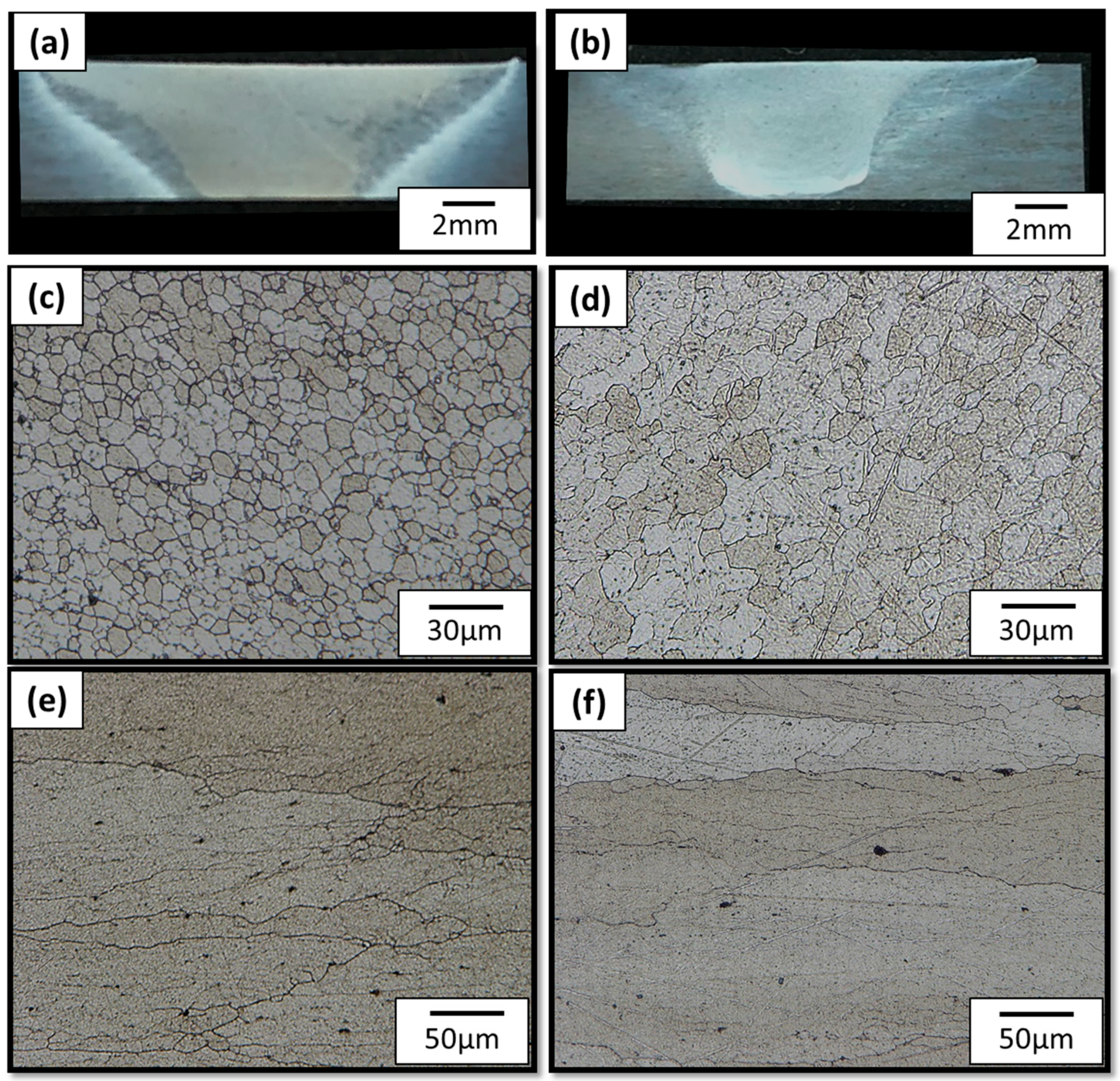
The etched transverse cross sections of welds produced from two different welding parameter sets are shown in Figure 2a,b. No void or large defects were observed in either of the transverse cross-sections. In both of the welds, four main regions can be identified: the stir zone (SZ), the thermo-mechanical affected zone (TMAZ), the heat affected zone (HAZ), and the base metal (BM). The macrographs include weld formation, and nugget widths were detected. Weld I showed a larger weld nugget due to the higher heat input associated with lower transverse speed. In contrast, Weld II exhibited a robust weld with a relatively small nugget zone, indicating sufficient heat input and appropriate stirring action that allowed for full plastic flow. The size of the weld nugget was inversely proportional to the transverse speed due to the linear heat input, as seen in other FSW aluminum alloys [1,2]. Figure 2c,d shows the stir zone in Weld I and Weld II. The microstructure of the SZ displays a fine dynamically recrystallized microstructure due to the high heat inputs and severe plastic deformation created from the direct contact with the rotating pin. The SZ in Weld I was considerably larger than that of Weld II. The HAZ of Welds I and II, shown in Figure 2e,f, did not experience any mechanical deformation and have similar grain structures to BM, but exhibit a decrease in hardness, attributable to the heat effects from the weld [30,31].
The AA2099 contains intermetallic particles that frequently contain low solubility elements, such as Fe, and are rich in Cu and Mn [1,41,42]. While both welds contain these intermetallic particles, Weld I had a much larger amount of these particles (Figure 2e,f). Due to the increased local shear stress caused by the micronotch, these intermetallic particles often served as a fatigue crack nucleation site during fatigue loading. This observation will be discussed in more detail later.

3.1.2. Microhardness

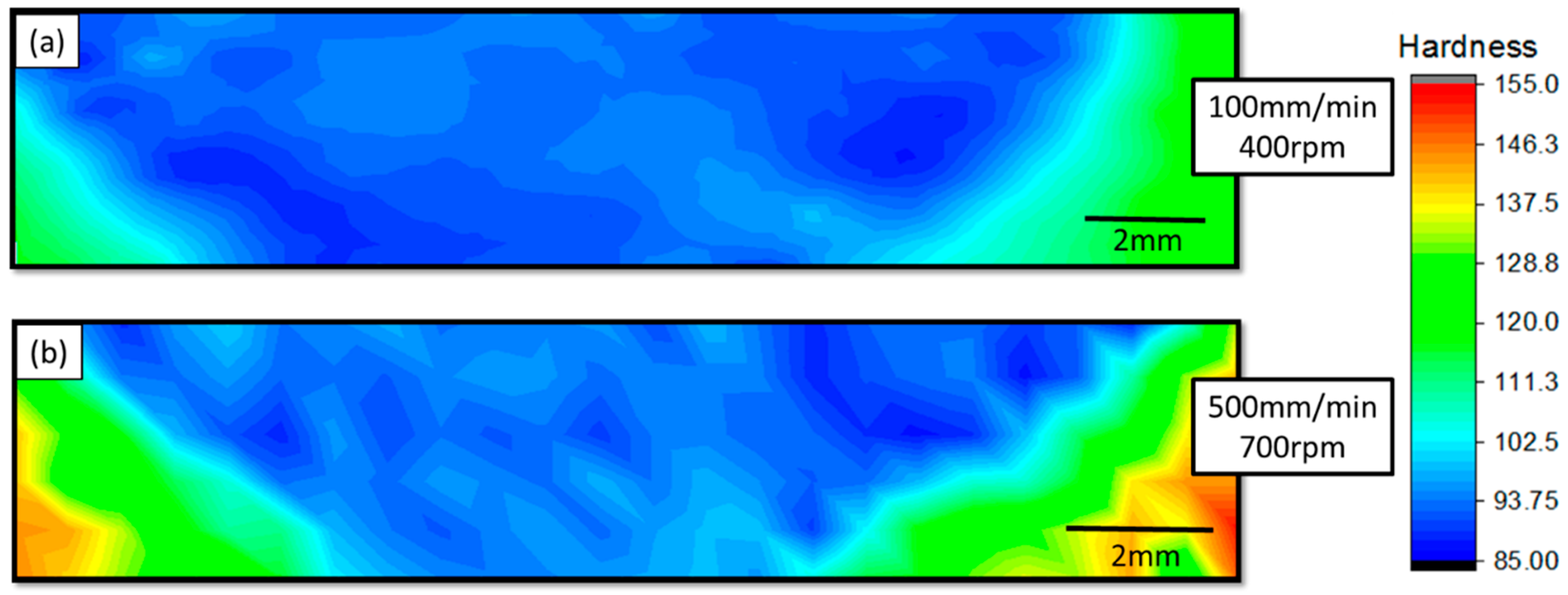
Figure 3a,b show the microhardness profiles across Weld I and Weld II. The hardness of the SZ was lower than that of the surrounding HAZ and considerably lower than that of the BM in both weld parameter sets. The BM exhibited the highest hardness due to it retaining the strengthening precipitates. Although Welds I and II displayed similar cross-section hardness profiles, the hardness values in the SZ of Weld I were slightly lower than those of Weld II. Weld I was produced at lower transverse speeds, which increased the linear heat input into the material, enabling further dissolution and coarsening of the strengthening phases. A smaller HAZ was observed in Weld II, resulting in higher hardness values closer to the weld center line. The higher transverse speed of Weld II reduced the linear heat input, and thus reduced the heat to dissipate, affecting less material.

3.1.3. Secondary Phase Characterization

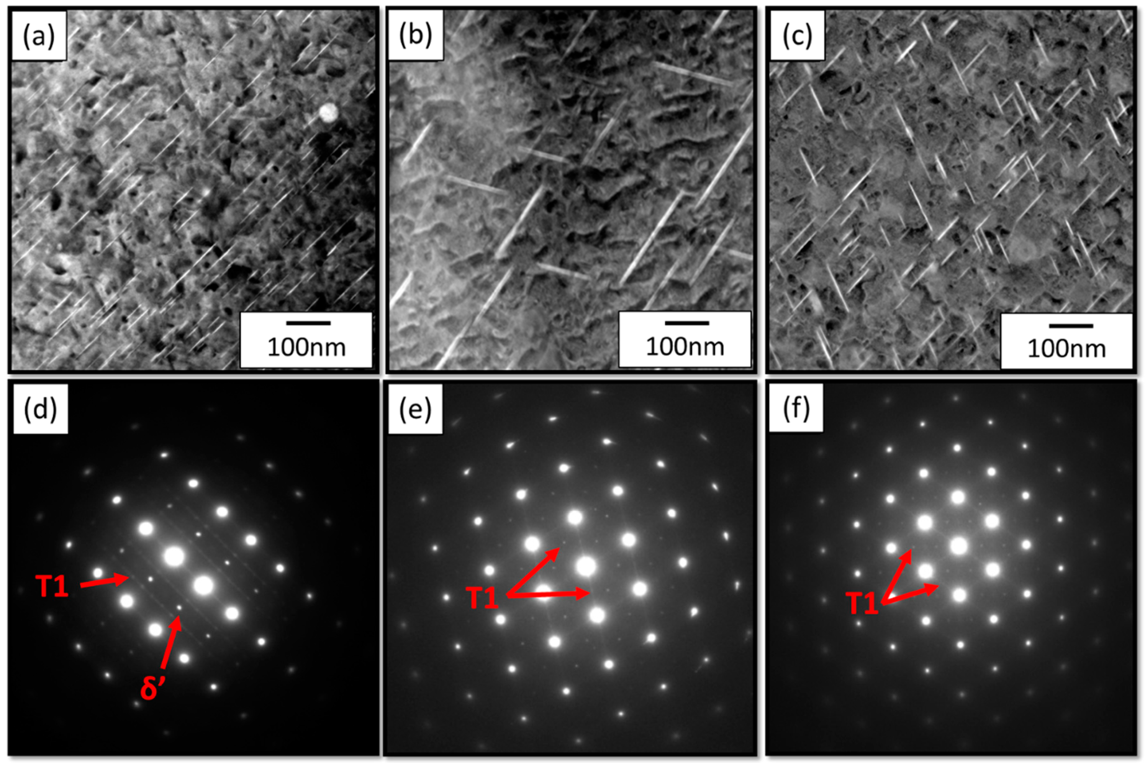
Figure 4 shows the nanoscale, secondary phase distribution in the BM of AA2099 and the HAZ of both welds observed by the HAADF-TEM technique. Both HAADF (Figure 4a–c) and diffraction patterns of those areas (Figure 4a–c) were observed. In these images, the level of brightness scales with the average atomic number of the particle (i.e., heavier particles show brighter contrast in comparison with the matrix). The T1 precipitates were Cu-rich and were seen as bright platelets, consistent with the literature [43]. These particles help to block dislocation movement within the material, and thus increase strength. The δ’ precipitates were Li-rich and were seen as dark, spherical (or dot-shaped) precipitates. Selected area diffraction (SAD) data from each corresponding region confirmed the identity of the T1 and delta-prime precipitates.
Depending on the FSW process parameters, the heat input varies, affecting the types and sizes of precipitates. Figure 4b shows the HAZ of the Weld I produced at 400 rpm and 100 mm/min. The fine plate-shaped T1 precipitates coarsened due to the heat input from FSW and were much larger (103–258 nm) than the BM (29–104 nm). Figure 4c shows the HAZ of a Weld II produced at 700 rpm and 500 mm/min. Due to the lower heat input seen with higher transverse speeds, the number of T1 strengthening precipitates seen was considerably higher than that of the previous weld. In addition, the precipitates had only coarsened slightly (37–125 nm) as compared to the BM (29–104 nm). The T1 precipitates coarsened considerably during FSW process I, but only marginally in FSW process II. With the increase in precipitate size, an increase in the spacing between precipitates became noticeable. This increase in spacing will reduce the Orowan strengthening for the material. The diffraction patterns taken from both welds showed no precipitates other than T1. The heat input from FSW caused the dissolution of the δ’ precipitates, resulting in the reduction of strength observed in the welds. The coarsening and dissolution of strengthening precipitates is commonly seen in other FSW Al–Li alloys [21,25,44].

3.2. Monotonic Stress–Strain Behavior

Figure 5 shows the experimental monotonic stress–strain curves for the BM AA2099 and the FSW AA2099 produced at 400 rpm and 100 mm/min and the FSW AA2099 produced at 700 rpm and 500 mm/min. The results of the tensile tests show evidence of work hardening in the BM. The two FSW conditions also show a slight level of work hardening but less than that of the BM. The ultimate and yield strength of the BM was significantly higher than those of the FSW specimens, indicating that the heat from the FSW process changed the microstructure and negatively impacted the strength. Additionally, FSW AA2099 produced at 700 rpm and 500 mm/min showed a higher ultimate and yield strength than the FSW AA2099 produced at 400 rpm and 100 mm/min, demonstrating 700 rpm and 500 mm/min to be more ideal process parameters.
Figure 6 shows the first and half-life stabilized hysteresis loops for FSW AA2099 at two different strain amplitudes. These loops were mainly symmetrical without any notable asymmetry, which is commonly seen due to the Bauschinger effect. All hysteresis loops displayed levels of strain hardening in the materials. At higher strain amplitudes, the level of strain hardening decreased, and the amount of plasticity increased. Figure 7a,c show representative hysteresis loops for the 0.4% strain amplitude for both welds. Welds produced at 400 rpm show a much higher level of plasticity than welds produced at 700 rpm due to the lower yield strength of welds produced at 400 rpm.

3.3. Low-Cycle Fatigue Parameters

Figure 7 shows the experimental strain-life results, with the engineering strain amplitude (mm/mm) plotted against the number of reversals to failure for completely reversed (R = −1) fatigue loading on both welds. Figure 7a shows the results associated with the AA2099 base metal. Note that at a strain amplitude of 0.002 the specimens did not fail, and an arrow denotes run-out. A linear relationship is in the log–log plot from 0.4% to 0.9%. Below a strain amplitude of 0.3%, the slope of the data changes. This behavior has been seen elsewhere and is due to the evolution from unconstrained microplasticity to constrained microplasticity [32,34,45]. For strain amplitudes below 0.3%, the loading is completely elastic. In contrast, at strain amplitudes above 0.1%, the plastic strain amplitude dominates. Figure 7b,c show the strain-life behavior for FSW AA2099 with process parameters 400 rpm and 100 mm/min (Weld I) and 700 rpm and 500 mm/min (Weld II). Both results are similar to the behavior seen in the base metal. A linear pattern was also observed, yet the evolution from low cycle to high cycle is less prominent than that of the base metal.
Figure 7d shows the strain-life fatigue results for BM and both FSWs. Overall, the BM demonstrates higher fatigue resistance in both high-cycle and low-cycle fatigue than the two FSW parameter sets. For low-cycle fatigue, the two welding parameters displayed similar fatigue results. However, in the high-cycle fatigue regime, Weld II (700 rpm and 500 mm/min) showed fatigue lives on the order of 1.5–2 times greater than the Weld I (400 rpm and 100 mm/min). This lower fatigue resistance of Weld I is due to the excessive dissolution and coarsening of the strengthening precipitates previously discussed.
While the two weld parameters exhibited similar but slightly different fatigue lives in the high cycle regime, the overall similarity of the performance of the welds was due to the lack volumetric defects. Since the welds produced in this study were free of volumetric defects, the mechanics of fatigue crack nucleation and small crack growth produced a similar number of cycles to failure. However, if one of the welding parameters contained large voids, we would expect to see a significantly different number of cycles to failure.
Also shown in Figure 7a–c are the strain-based model correlations and the corresponding parameters. The total strain-life, including both the elastic and plastic regimes, was plotted with the strain-life equation shown below:
Δ ε T o t a l 2 = Δ ε e 2 + Δ ε P 2
where Δ ε T o t a l 2 is the total strain amplitude, Δ ε e 2 is the elastic strain amplitude, and Δ ε P 2 is the plastic strain amplitude. The Basquin equation represents the elastic strain amplitude, and the Coffin–Manson relationship was used for the plastic strain amplitude, as shown in Equations (12) and (13):
Δ ε e 2 = σ f E ( 2 N f ) b
Δ ε p 2 = ε f ( 2 N f ) c
where E is the elastic modulus, σ f is the fatigue strength coefficient, b is the fatigue strength exponent, 2 N f is the number of reversals to failure, ε f is the fatigue ductility coefficient, and c is the fatigue ductility exponent. In Figure 7, the symbols represent the experimental results from this study, the solid line is the total strain-life equation, and the dashed and dotted lines are the elastic and plastic strain components, respectively. Table 2 shows the strain-life fatigue parameters and constants used for determining the cyclic stress–strain behavior of the BM and both FSWs.

3.4. Fracture Analysis

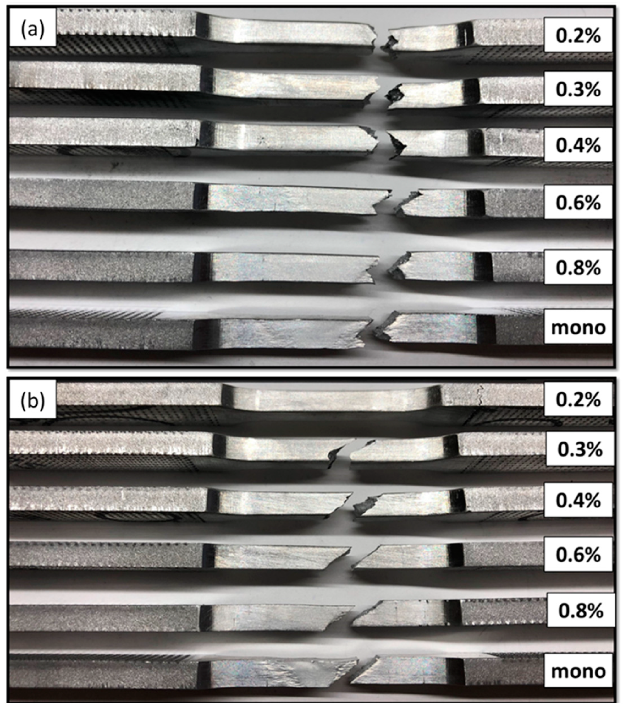
Figure 8 shows the representative fractured specimens of FSW AA2099 for welds produced at 400 rpm and 100 mm/min (Weld I) and 700 rpm and 500 mm/min (Weld II) after strain-controlled fatigue testing. Examination of the fracture surfaces revealed that Weld I specimens failed along the TMAZ/HAZ region on the retreating side and exhibited a tumultuous surface. Weld II specimens failed along a 45-degree angle. Strong crystallographic texture existing in Al–Li alloys caused crack deflection resulting in these fractured surfaces [46,47,48]. Interestingly, Weld II specimens failed closer to the weld nugget due to the smaller HAZ associated with this parameter set.
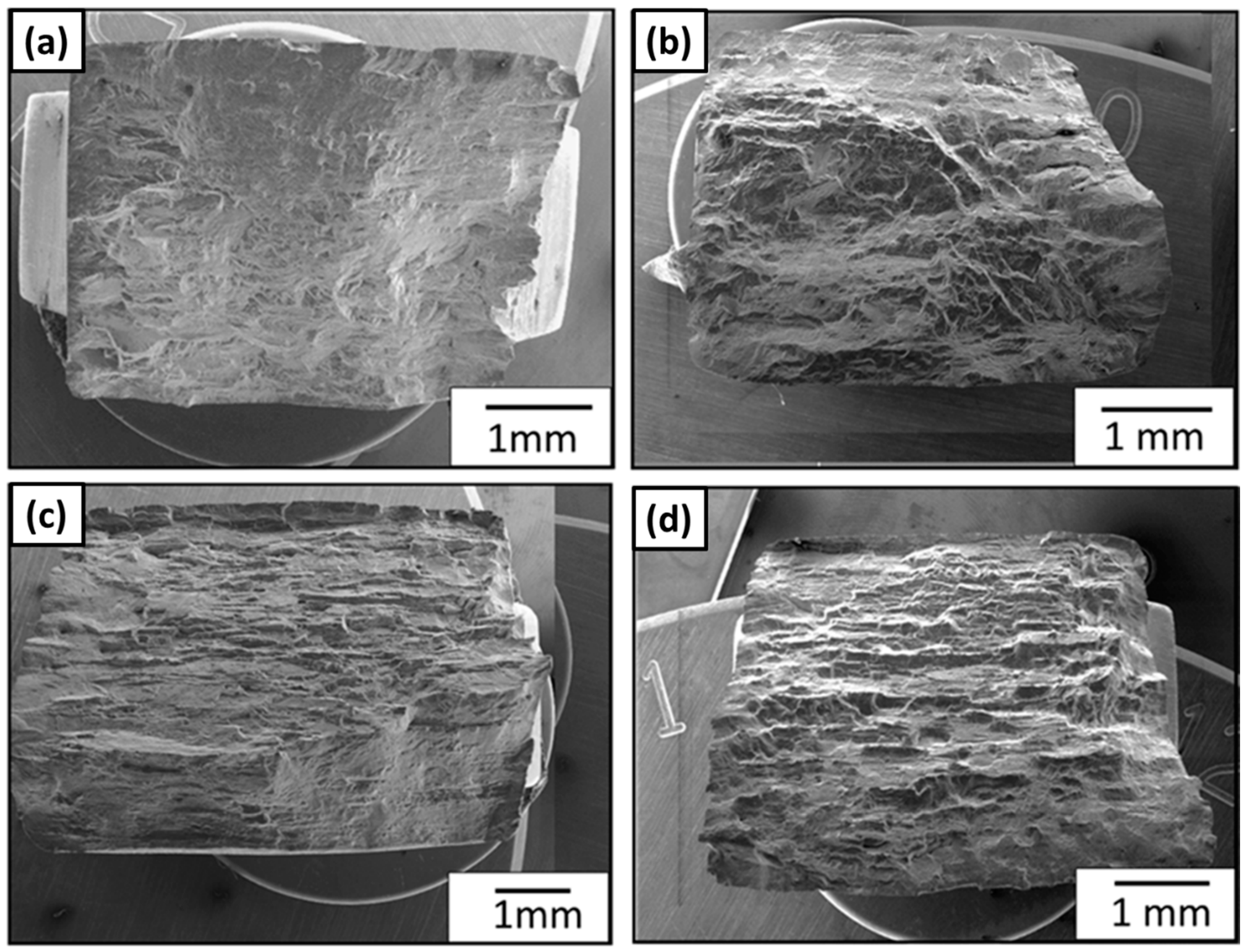
Figure 9a,c display the overview of the fracture surfaces of Weld I specimens tested at 0.3% and 0.8% strain amplitudes. Figure 9b,d display the overview of the fracture surfaces of Weld 2 specimens tested at 0.3% and 0.8% strain amplitudes. The fracture surfaces revealed surface crack initiation (SCI) and interior crack initiation (ICI) sites. For lower strain amplitudes shown in Figure 9a,b, the fracture surface was characterized by a very tumultuous fracture path and both types of crack initiation. While higher strain amplitudes shown in Figure 9c,d had fracture surfaces characterized by a shear fracture path originating from surface crack initiations.
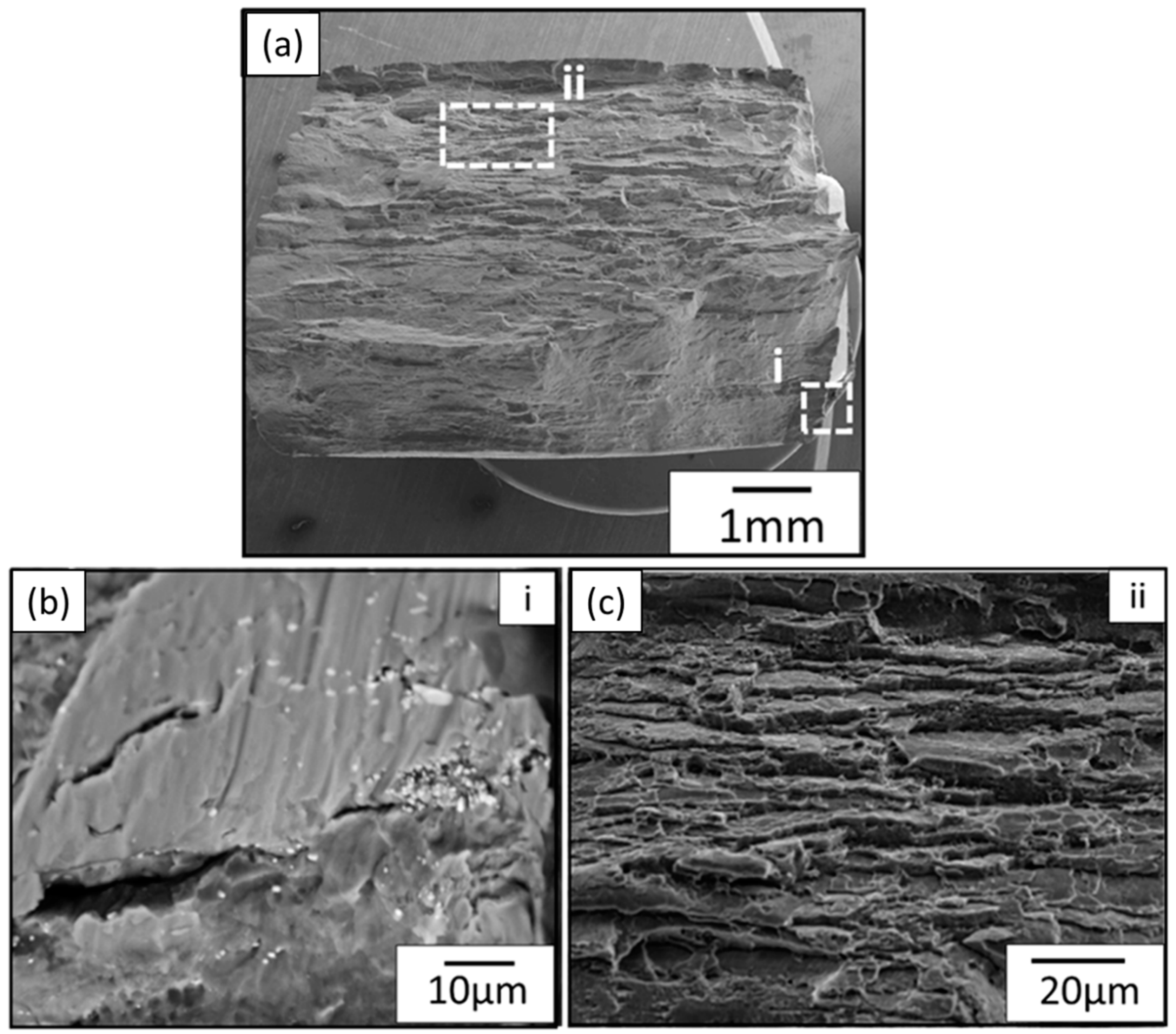
Figure 10 shows a representative crack initiation site on the fracture surface corresponding to a tool rotational rate of 700 rpm and a transverse speed of 500 mm/min tested at a 0.3% strain amplitude. As seen in Figure 10a, the crack nucleated at the bottom right hand side of the fractured surface. A secondary crack is seen to initiate from a cracked particle within the interior of the surface as shown in Figure 10b. This evidence of cracked particles is seen in literature of other Al–Li alloys [22,49]. A higher magnification image of the crack initiation site is shown in Figure 10c. An inclusion is seen to initiate a crack with fatigue striations at the nucleation site, as commonly observed in other aluminum alloys.
Figure 11 shows a representative crack initiation site on the fracture surface corresponding to Weld I tested at a 0.8% strain amplitude. As seen in Figure 11a, there are multiple crack nucleation sites on the crown and root of the weld. Smooth, faceted surface and ductile feature characteristic types of fracture were observed. A closer examination of one of the crack initiation sites shown in Figure 11b shows that an agglomeration of small secondary phase particles initiated a crack. Crack branching and secondary cracks can be observed originating from the main larger crack. Zhong et al. [49] also observed crack bifurcation and secondary cracks originating from brittle grain boundaries. Figure 11c shows a fast fracture region on the fractured surface. The fractures occurred in the HAZ displaying elongated grains from rolling with delaminated features on perceived slip bands as shown in Figure 11b. Huang et al. [50] and Kalyanam et al. [51] reported similar fatigue mechanisms in Al–Li alloys. In general, the fatigue fracture surfaces were characterized by fatigue striations and secondary particles.

3.5. MSF Model Correlation

The total fatigue life in the MSF model employed to model the AA2099 joined by FSW was separated into two main stages: the number of cycles to incubate a crack and the number of cycles for the MSC/PSC growth stage. The incubation stage, which is based on the number of cycles to incubate a crack through the micronotch root plasticity zone, is a function of shear strain developed at micronotches. In the MSC/PSC stage, the cyclic crack tip plasticity is the dominant factor in crack growth. For this study, the MSF model captured the underling effects of the FSW process on the fatigue life by using the experiments performed in Section 3.1, Section 3.2, Section 3.3 and Section 3.4 to calibrate the model. To enhance the model’s receptiveness to variation in microstructure and to better capture competing mechanisms of grain size influence and hardness due to the effects of FSW, the term ϖ (Equation (3)) was used as a relationship that integrates experimentally observed microstructural characteristics, such as grain size and hardness variation in the weld. The MSF parameters used in this study are listed in Table 3.
Figure 12 shows the fatigue life with an MSF model fit to the results for the BM (Figure 12a), FSW AA2099 produced at 400 rpm and 100 mm/min (Figure 12b), and FSW AA2099 produced at 700 rpm and 500 mm/min (Figure 12c). The material parameters yield strength (σy), ultimate strength (σult), hardness, and grain size were determined through experimental data analysis and used in calibrating the model. The MSF model was able to accurately correlate the experimental data performed by varying the material parameters determined from material characterization efforts. To appropriately analyze the total fatigue life, the MSF model was discretized into estimations for the incubation and crack growth stages. As such, the MSF model reveals that small crack growth dominates total fatigue life for high-strain amplitudes, and the incubation stage is dominant in the total fatigue life for low-strain amplitudes. Figure 12d shows model fits for the base metal and both welding parameter sets, showing the model’s capability to capture the effects of FSW on the fatigue life.

4. Conclusions

In this study the effects of friction stir welding (FSW) on the fatigue properties of AA2099 were examined. Based on the results of this study, the following conclusions were made:
  • AA2099 was successfully friction stir welded free of large voids or welding defects. In both of the welds, four characteristic regions could be identified: the stir zone (SZ), the thermo-mechanical affected zone (TMAZ), the heat-affected zone (HAZ), and base metal (BM).
  • The SZ in Weld II was considerably smaller than that of Weld I, yet the grain size in the SZ of Weld I was smaller than that of Weld II. These size effects were correlated to the heat inputs.
  • Although Welds I and II displayed similar cross-section hardness profiles, the hardness values in the SZ of weld I were slightly lower than those of Weld II. Weld I was produced at a lower transverse speed, which increased the heat input in the material and further enabled the dissolution of strengthening precipitates resulting in these lower values.
  • The heat input of the FSW process enabled the dissolution of the strengthening precipitate δ’ and the dissolution or coarsening of fine T1 precipitates. Welds I and II had lower amounts of T1 particles than that in the BM. Although the sizes of the T1 precipitates in Weld II increased in relation to the BM, they were noticeably smaller than those of Weld I.
  • For strain amplitudes below 0.3%, the elastic strain amplitude was significant in the cyclic deformation. In contrast, at strains amplitudes above 0.1%, the plastic strain amplitude was the dominant factor.
  • Overall, the base material demonstrated higher fatigue resistance in both high-cycle and low-cycle fatigue than the FSW specimens.
  • For low-cycle fatigue, the two welded parameters displayed similar fatigue results.
  • The high-cycle fatigue of Weld II (700 rpm and 500 mm/min) showed fatigue lives 1.5–2 times greater than that of Weld I (400 rpm and 100 mm/min).
  • Fracture specimens displayed crack deflection, delamination failure features commonly observed in Al–Li alloys. Fatigue cracks initiated at particles located near the surface of the samples.
  • The MSF model was successfully modified to account for competing effects of grain size and hardness variations within an FSW.

Author Contributions

Conceptualization, A.R.C., J.B.J. and P.G.A. Formal analysis, A.R.C., J.B.J., and L.N.B. Funding acquisition, T.W.R. and L.G.; Investigation, A.R.C., D.Z.A., and T.L.; Project administration, T.W.R. and L.G.; Software, R.L.C. and Y.H. Writing–original draft, A.R.C. and J.B.J.; Writing–review & editing, J.B.J., L.N.B., P.G.A., T.W.R. and L.G.

Funding

The authors would like to thank Zach McClelland for providing the AA2099 material. In addition, the authors thank Robert Amaro for his helpful comments. A portion of this work was performed under the auspices of the U.S. Army Engineer Research and Development Center, administered by CEED, Subcontract No. W15QKN-13-9-001. Permission to publish was granted by the Director, Geotechnical and Structures Laboratory.

Conflicts of Interest

The authors declare no conflict of interest.

References

  1. Bois-Brochu, A.; Blais, C.; Tchitembo Goma, F.A.; Larouche, D. Modelling of anisotropy for Al-Li 2099 T83 extrusions and effect of precipitate density. Mater. Sci. Eng. A 2016, 673, 581–586. [Google Scholar] [CrossRef]
  2. Sidhar, H.; Mishra, R.S. Aging kinetics of friction stir welded Al-Cu-Li-Mg-Ag and Al-Cu-Li-Mg alloys. Mater. Des. 2016, 110, 60–71. [Google Scholar] [CrossRef]
  3. Jordon, J.B.; Rao, H.M.; Yuan, W.; Badarinarayan, H.; Ghaffari, B. Effect of process parameters on microstructure and mechanical behaviors of friction stir linear welded aluminum to magnesium. Mater. Sci. Eng. A 2015, 651, 27–36. [Google Scholar]
  4. Chiumenti, M.; Cervera, M.; Agelet de Saracibar, C.; Dialami, N. Numerical modeling of friction stir welding processes. Comput. Methods Appl. Mech. Eng. 2013, 254, 353–369. [Google Scholar] [CrossRef]
  5. Mishra, R.S.; Ma, Z.Y. Friction stir welding and processing. Mater. Sci. Eng. R Rep. 2005, 50, 1–78. [Google Scholar] [CrossRef]
  6. Michael, J. Troughton Friction Stir Welding. Weld. J. 2009, 8, 131–134. [Google Scholar]
  7. Gibson, B.T.; Lammlein, D.H.; Prater, T.J.; Longhurst, W.R.; Cox, C.D.; Ballun, M.C.; Dharmaraj, K.J.; Cook, G.E.; Strauss, A.M. Friction stir welding: Process, automation, and control. J. Manuf. Process. 2014, 16, 56–73. [Google Scholar] [CrossRef]
  8. Su, J.Q.; Nelson, T.W.; Mishra, R.; Mahoney, M. Microstructural investigation of friction stir welded 7050-T651 aluminium. Acta Mater. 2003, 51, 713–729. [Google Scholar] [CrossRef]
  9. Da Silva, A.A.M.; Arruti, E.; Janeiro, G.; Aldanondo, E.; Alvarez, P.; Echeverria, A. Material Flow and Mechanical Behaviour of Dissimilar AA2024-T3 and AA7075-T6 Aluminium Alloys Friction Stir Welds. Mater. Des. 2011, 32, 2021–2027. [Google Scholar] [CrossRef]
  10. John, R.; Jata, K.V.; Sadananda, K. Residual stress effects on near-threshold fatigue crack growth in friction stir welds in aerospace alloys. Int. J. Fatigue 2003, 25, 939–948. [Google Scholar] [CrossRef]
  11. Fratini, L.; Pasta, S.; Reynolds, A.P. Fatigue crack growth in 2024-T351 friction stir welded joints: Longitudinal residual stress and microstructural effects. Int. J. Fatigue 2009, 31, 495–500. [Google Scholar] [CrossRef]
  12. Cavaliere, P.; De Santis, A.; Panella, F.; Squillace, A. Effect of welding parameters on mechanical and microstructural properties of dissimilar AA6082-AA2024 joints produced by friction stir welding. Mater. Des. 2009, 30, 609–616. [Google Scholar] [CrossRef]
  13. Ciliberto, S.; Astarita, A.; Squillace, A. FSW of T joints in overlap configuration: Process optimization in joining dissimilar aluminium alloys for the aeronautic application. Surf. Interface Anal. 2013, 45, 1631–1637. [Google Scholar] [CrossRef]
  14. Sepe, R.; Armentani, E.; Di Lascio, P.; Citarella, R. Crack Growth Behavior of Welded Stiffened Panel. Procedia Eng. 2015, 109, 473–483. [Google Scholar] [CrossRef] [Green Version]
  15. Ghaffari, B.; Khosrovaneh, A.K.; Su, X.; Jordon, J.B.; Rao, H.M.; Lee, Y.L.; Yuan, W. Fatigue Behavior of Friction Stir Linear Welded Dissimilar Aluminum-to-Magnesium Alloys. In Friction Stir Welding and Processing VIII; Springer: New York City, NY, USA, 2016; Volume 82, pp. 145–152. [Google Scholar]
  16. Solanki, K.N.; Jordon, J.B.; Whittington, W.; Rao, H.; Hubbard, C.R. Structure–property relationships and residual stress quantification of a friction stir spot welded magnesium alloy. Scr. Mater. 2012, 66, 797–800. [Google Scholar] [CrossRef]
  17. WANG, S.; HUANG, Y.; ZHAO, L. Effects of different aging treatments on microstructures and mechanical properties of Al-Cu-Li alloy joints welded by electron beam welding. Chin. J. Aeronaut. 2018, 31, 363–369. [Google Scholar] [CrossRef]
  18. Yang, W.; Zhang, X.; Li, L.; Huang, T.; Liu, Z.; Xiao, R. Microstructure and mechanical properties of laser beam-welded AA2060 Al-Li alloy. J. Mater. Process. Technol. 2016, 237, 301–308. [Google Scholar]
  19. Fu, B.; Qin, G.; Meng, X.; Ji, Y.; Zou, Y.; Lei, Z. Microstructure and mechanical properties of newly developed aluminum-lithium alloy 2A97 welded by fiber laser. Mater. Sci. Eng. A 2014, 617, 1–11. [Google Scholar] [CrossRef]
  20. Ma, Y.E.; Xia, Z.C.; Jiang, R.R.; Li, W.Y. Effect of welding parameters on mechanical and fatigue properties of friction stir welded 2198 T8 aluminum lithium alloy joints. Eng. Fract. Mech. 2013, 114, 1–11. [Google Scholar] [CrossRef]
  21. Lee, H.S.; Yoon, J.H.; Yoo, J.T.; No, K. Friction stir welding process of aluminum-lithium alloy 2195. Procedia Eng. 2016, 149, 62–66. [Google Scholar] [CrossRef]
  22. Tao, Y.; Ni, D.R.; Xiao, B.L.; Ma, Z.Y.; Wu, W.; Zhang, R.X.; Zeng, Y.S. Origin of unusual fracture in stirred zone for friction stir welded 2198-T8 Al-Li alloy joints. Mater. Sci. Eng. A 2017, 693, 1–13. [Google Scholar] [CrossRef]
  23. Sili, A.; Calogero, V.; Costanza, G.; Tata, M.E.; Missori, S. A Weldability Study of Al–Cu–Li 2198 Alloy. Metallurgist 2014, 57, 1134–1141. [Google Scholar] [Green Version]
  24. Cai, B.; Zheng, Z.Q.; He, D.Q.; Li, S.C.; Li, H.P. Friction stir weld of 2060 Al-Cu-Li alloy: Microstructure and mechanical properties. J. Alloys Compd. 2015, 649, 19–27. [Google Scholar] [CrossRef]
  25. Mao, Y.; Ke, L.; Liu, F.; Huang, C.; Chen, Y.; Liu, Q. Effect of welding parameters on microstructure and mechanical properties of friction stir welded joints of 2060 aluminum lithium alloy. Int. J. Adv. Manuf. Technol. 2015, 81, 1419–1431. [Google Scholar] [CrossRef]
  26. Giles, T.L.; Oh-Ishi, K.; Zhilyaev, A.P.; Swaminathan, S.; Mahoney, M.W.; McNelley, T.R. The effect of friction stir processing on the microstructure and mechanical properties of an aluminum lithium alloy. Metall. Mater. Trans. A 2009, 40, 104–115. [Google Scholar] [CrossRef]
  27. Gao, C.; Zhu, Z.; Han, J.; Li, H. Correlation of microstructure and mechanical properties in friction stir welded 2198-T8 Al-Li alloy. Mater. Sci. Eng. A 2015, 639, 489–499. [Google Scholar] [CrossRef]
  28. Bitondo, C.; Prisco, U.; Squilace, A.; Buonadonna, P.; Dionoro, G. Friction-stir welding of AA 2198 butt joints: mechanical characterization of the process and of the welds through DOE analysis. Int. J. Adv. Manuf. Technol. 2011, 53, 505–516. [Google Scholar] [CrossRef]
  29. Moreira, P.M.G.P.; de Jesus, A.M.P.; de Figueiredo, M.A.V.; Windisch, M.; Sinnema, G.; de Castro, P.M.S.T. Fatigue and fracture behaviour of friction stir welded aluminium–lithium 2195. Theor. Appl. Fract. Mech. 2012, 60, 1–9. [Google Scholar] [CrossRef]
  30. Akhtar, N.; Jin, H.J.; Jia, F.; Wu, S.J. Fatigue crack growth rates in friction stir welding joints of Al-Li 2060-T8X Alloy. In Proceedings of the 2015 12th International Bhurban Conference on Applied Sciences and Technology, IBCAST 2015, Islamabad, Pakistan, 13–17 January 2015; pp. 6–13. [Google Scholar]
  31. McDowell, D.L. Simulation-based strategies for microstructure-sensitive fatigue modeling. Mater. Sci. Eng. A 2007, 468–470, 4–14. [Google Scholar] [CrossRef]
  32. Xue, Y.; McDowell, D.L.; Horstemeyer, M.F.; Dale, M.H.; Jordon, J.B. Microstructure-based multistage fatigue modeling of aluminum alloy 7075-T651. Eng. Fract. Mech. 2007, 74, 2810–2823. [Google Scholar] [CrossRef]
  33. Horstemeyer, M.F.; Baird, J.C.; Jordon, J.B.; Gibson, J.B.; Luo, A.A.; Kadiri, H. El Effect of twinning, slip, and inclusions on the fatigue anisotropy of extrusion-textured AZ61 magnesium alloy. Mater. Sci. Eng. A 2011, 528, 6860–6871. [Google Scholar]
  34. Rettberg, L.H.; Jordon, J.B.; Horstemeyer, M.F.; Jones, J.W. Low-Cycle Fatigue Behavior of Die-Cast Mg Alloys AZ91 and AM60. Metall. Mater. Trans. A 2012, 43, 2260–2274. [Google Scholar] [CrossRef]
  35. Allison, P.G.; Hammi, Y.; Jordon, J.B.; Horstemeyer, M.F. Modelling and experimental study of fatigue of powder metal steel (FC-0205). Powder Metall. 2013, 56, 388–396. [Google Scholar] [CrossRef] [Green Version]
  36. Jordon, J.B.; Horstemeyer, M.F.; Yang, N.; Major, J.F.; Gall, K.A.; Fan, J.; McDowell, D.L. Microstructural Inclusion Influence on Fatigue of a Cast A356 Aluminum Alloy. Metall. Mater. Trans. A 2009, 41, 356–363. [Google Scholar] [CrossRef]
  37. Rodriguez, R.I.; Jordon, J.B.; Allison, P.G.; Rushing, T.; Garcia, L. Low-cycle fatigue of dissimilar friction stir welded aluminum alloys. Mater. Sci. Eng. A 2016, 654, 236–248. [Google Scholar] [CrossRef]
  38. McCullough, R.R.; Jordon, J.B.; Brammer, A.T.; Manigandan, K.; Srivatsan, T.S.; Allison, P.G.; Rushing, T.W. A Fatigue Model for Discontinuous Particulate-Reinforced Aluminum Alloy Composite: Influence of Microstructure. J. Mater. Eng. Perform. 2013, 23, 65–76. [Google Scholar] [CrossRef]
  39. Jordon, J.B.; McCullough, R.R.; Garcia, L.; Rushing, T.; Allison, P.G. Fatigue crack nucleation and small crack growth in an extruded 6061 aluminum alloy. Int. J. Fatigue 2018, 119, 52–61. [Google Scholar]
  40. Rodriguez, R.I.; Jordon, J.B.; Allison, P.G.; Rushing, T.W.; Garcia, L. Corrosion effects on fatigue behavior of dissimilar friction stir welding of high-strength aluminum alloys. Mater. Sci. Eng. A 2019, 742, 255–268. [Google Scholar] [CrossRef]
  41. Armel, F.; Goma, T.; Larouche, D.; Bois-brochu, A.; Blais, C.; Boselli, J. Effect of extrusion aspect ratio and test temperatures on fatigue crack growth behavior of a 2099-T83 Al – Li alloy. Int. J. Fatigue 2014, 59, 244–253. [Google Scholar]
  42. Ma, Y.; Zhou, X.; Thompson, G.E.; Hashimoto, T.; Thomson, P.; Fowles, M. Distribution of intermetallics in an AA 2099-T8 aluminium alloy extrusion. Mater. Chem. Phys. 2011, 126, 46–53. [Google Scholar] [CrossRef]
  43. Lin, Y.; Zheng, Z. Microstructural evolution of 2099 Al Li alloy during friction stir welding process. Mater. Charact. 2017, 123, 307–314. [Google Scholar] [CrossRef]
  44. Lin, Y.; Zheng, Z.; Li, S.; Kong, X.; Han, Y. Microstructures and properties of 2099 Al-Li alloy. Mater. Charact. 2013, 84, 88–99. [Google Scholar] [CrossRef]
  45. McDowell, D.L.; Gall, K.; Horstemeyer, M.F.; Fan, J. Microstructure-based fatigue modeling of cast A356-T6 alloy. Eng. Fract. Mech. 2003, 70, 49–80. [Google Scholar] [CrossRef] [Green Version]
  46. Chen, D.L.; Chaturvedi, M.C. Near-threshold fatigue crack growth behavior of 2195 aluminum-lithium-alloy-prediction of crack propagation direction and influence of stress ratio. Metall. Mater. Trans. A 2000, 31, 1531–1541. [Google Scholar] [CrossRef]
  47. Wang, L.; Xu, Y.B.; Wang, Z.G.; Zhang, Y.; Hu, Q.Z. Fatigue and fracture behavior of an aluminum-lithium alloy 8090-T6 at ambient and cryogenic temperature. Metall. Trans. A 2007, 22, 723–729. [Google Scholar]
  48. Wu, X.J.; Wallace, W.; Raizenne, M.D.; Koul, A.K. The orientation dependence of fatigue-crack growth in 8090 Al-Li plate. Metall. Mater. Trans. A 1994, 25, 575–588. [Google Scholar] [CrossRef]
  49. Zhong, J.; Zhong, S.; Zheng, Z.Q.; Zhang, H.F.; Luo, X.F. Fatigue crack initiation and early propagation behavior of 2A97 Al-Li alloy. Trans. Nonferrous Met. Soc. China (English Ed.) 2014, 24, 303–309. [Google Scholar] [CrossRef]
  50. Huang, Y.; Liu, J.Z.; Huang, X.; Zhang, J.Z.; Yue, G.Q. Fatigue crack growth and delamination behaviours of advanced Al-Li alloy laminate under single tensile overload. Fatigue Fract. Eng. Mater. Struct. 2016, 39, 47–56. [Google Scholar] [CrossRef]
  51. Kalyanam, S.; Beaudoin, A.J.; Dodds, R.H.; Barlat, F. Delamination cracking in advanced aluminum—lithium alloys—Experimental and computational studies. Eng. Fract. Mech. 2009, 76, 2174–2191. [Google Scholar] [CrossRef]
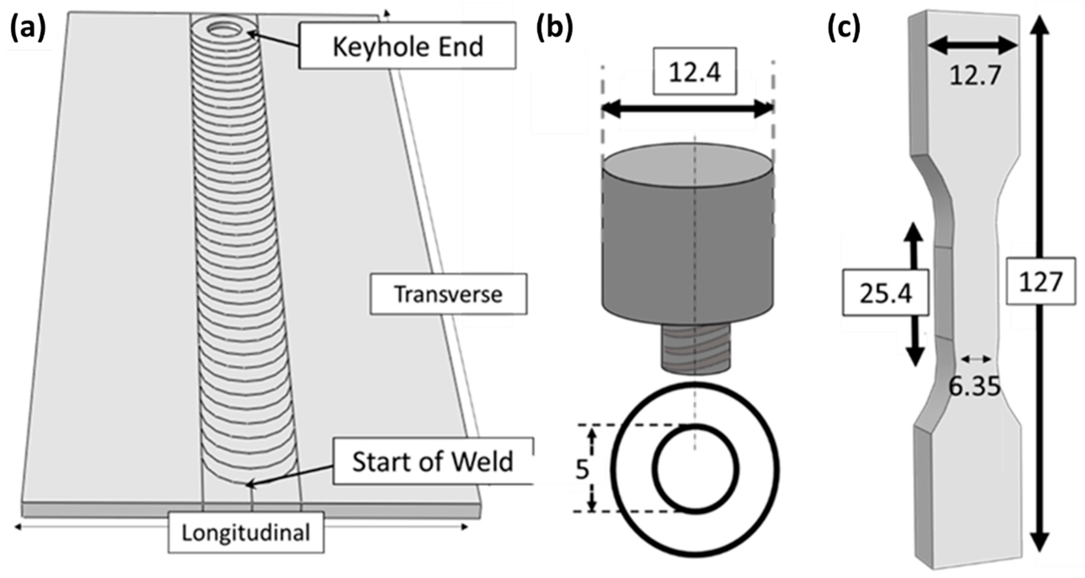
Figure 1. (a) Welding schematic, (b) pin tool schematic, and (c) fatigue test specimen geometry (all dimensions are in mm).
Metals 09 00293 g001
Figure 2. Optical micrographs showing (ab) macro views of the cross-section; (cd) microstructures in the stir zone (SZ); and (ef) heat affected zones (HAZs) of welds produced at (a,c,e). Weld I: 400 rpm and 100 mm/min and (b,d,f). Weld II: 700 rpm and 500 mm/min.
Metals 09 00293 g002
Figure 3. Microhardness profiles obtained from welds produced at (a) Weld I: 400 rpm, 100 mm/min and (b) Weld II: 700 rpm, 500 mm/min. Note that all values of hardness are shown in Vickers hardness (HV).
Metals 09 00293 g003
Figure 4. High-angle annular dark-field scanning transmission electron microscopy images of (a) base metal viewed along the <112>Al zone axis, (b) Weld I (400 rpm and 100 mm/min) viewed along the <011>Al zone axis, (c) Weld II (700 rpm and 500 mm/min) viewed along the <011>Al zone axis, and (df) the corresponding selected area diffraction patterns from the regions shown in (ac).
Metals 09 00293 g004
Figure 5. Monotonic stress–strain comparison of AA2099 base material and FSW AA2099 with parameters 700 rpm and 500 mm/min, and 400 rpm and 100 mm/min, respectively.
Metals 09 00293 g005
Figure 6. Hysteresis loops for welds produced at (a,b) 400 rpm and 100 mm/min and (c,d) 700 rpm and 500 mm/min for (a,c) 0.4% strain amplitude and (b,d) 0.8% strain amplitude first cycle and half life cycle.
Metals 09 00293 g006
Figure 7. Strain-life fatigue behavior of (a) base metal, (b) Weld I (400 rpm/100 mm/min), (c) Weld II (700 rpm/500 mm/min), and (d) comparison between the fatigue lives of the base metal and both welds.
Metals 09 00293 g007
Figure 8. Optical macrographs showing the failure locations at various strain amplitudes for (a) Weld I and (b) Weld II.
Metals 09 00293 g008
Figure 9. Optical micrographs showing the fracture surfaces for the Weld I processed at 400 rpm and 100 mm/min (a,c) and the Weld II processed at 700 rpm and 500 mm/min (b,d) and tested under cyclic loading at 0.3% (a,b) and 0.8% (c,d) strain amplitude.
Metals 09 00293 g009
Figure 10. (a) Representative fracture surface for the weld produced at a tool rotational speed of 400 rpm and tested at 0.2% strain amplitude. (b) Backscatter electron image showing the morphology of the fractured secondary particles in Region i. (c) Magnified images of a crack initiation site in Region ii.
Metals 09 00293 g010
Figure 11. (a) Representative fracture surface for the Weld II tested at 0.2% strain amplitude. (b) Magnified image of a crack initiation site in Region i. (c) Backscatter electron image showing the morphology of the fractured secondary particles in Region ii.
Metals 09 00293 g011
Figure 12. MSF model correlation for (a) the BM, (b) FSW AA2099 produced at 400 rpm and 100 mm/min, (c) FSW AA2099 produced at 700 rpm and 500 mm/min., and (d) MSF model fits for the BM and both welding parameter sets.
Metals 09 00293 g012
Table 1. Nominal composition for AA2099.
Chemical Composition Limits of Wrought AA2099 (Weight %)
ElementsCuLiZnMgMnZrTiFeSiAl
Min2.401.600.400.100.100.05---Remainder
Max3.002.001.000.500.500.120.100.070.05Remainder
Table 2. Summary of the low-cycle fatigue properties for the base metal, Weld I, and Weld II.
Low Cycle Fatigue ParametersAl–Li Alloy 2099 (BM)Weld I (400 rpm
100 mm/min)
Weld II (700 rpm
500 mm/min)
Cyclic strain-hardening exponent n0.06010.1230.147
Cyclic strength coefficient K′, MPa664666.4798.5
Fatigue strength coefficient σ f , MPa1009515559
Fatigue strength exponent b−0.126−0.084−0.089
Fatigue ductility coefficient ε f 0.6480.12310.0884
Fatigue ductility exponent c−0.899−0.684−0.604
Table 3. Microstructure-sensitive fatigue modeling parameters for FSW AA2099.
CoefficientsAA 2099 Base MetalWeld I:
400 rpm and 100 mm/min
Weld II:
700 rpm and 500 mm/min
Ultimate Strength
(MPa)
558342390
Yield Strength
(MPa)
510245284
Grain Size
(µm)
10002035
Hardness
(HV)
1558398