Arc-Assisted Laser Welding Brazing of Aluminum to Steel


1
School of Materials Science and Engineering, Lanzhou University of Technology, Lanzhou 730050, China
2
State Key Laboratory of Advanced Processing and Recycling of Non-ferrous Metal, Lanzhou University of Technology, Lanzhou 730050, China
*
Authors to whom correspondence should be addressed.
Metals 2019, 9(4), 397; https://doi.org/10.3390/met9040397
Submission received: 2 March 2019
/
Revised: 24 March 2019
/
Accepted: 27 March 2019
/
Published: 31 March 2019
(This article belongs to the Special Issue Dissimilar Metal Welding)
Abstract
:Using laser beam as main heat source, and trailing arc as an assisted role, aluminum alloy was joined to galvanized steel in a butt configuration. Under suitable welding parameters, a sound welding seam was obtained. The interface intermetallic compounds layer and wetting behavior of weld joint were studied. The assisted arc can improve the wetting and spreading ability of weld pool duo to large temperature field. There are two different types of IMCs: near to the steel side one is Fe2Al5 with tooth-like shape and near to the weld seam side is the other one Fe4Al13 with flocculent-like shape. The highest tensile strength can reach 163 MPa when the fracture occurred at the weld seam.
1. Introduction
In recent years, low carbon emission and lightweight design have been concerned by the automobile industry [1]. Using the aluminum and steel hybrid structure to replace the traditional single steel structure can effectively reduce the weight of the car body [2]. However, there are some differences of physical properties between aluminum and steel, such as the melting point and the linear expansion coefficient, etc. It is difficult to realize the metallurgical bonding using the conventional fusion welding.
To realize a high quality welding of aluminum and steel welding, the welding brazing method was proposed. [3]. In the welding brazing process, the heat source is mainly used for melting the base metal with lower melting point, and then the brazing joint was formed by wetting of molten metal [4]. There are various investigations on the aluminum and steel welding brazing process, including laser beam welding [4,5,6], CMT (cold metal transfer) welding [7,8,9], and TIG (tungsten inert gas) arc welding [10,11]. However, there are two major issues that have limited the welding brazing of steel and aluminum; one is the poor wetting ability of weld pool, and the other is the generation of brittle and hard intermetallic compounds (IMC), which can introduce deleterious effect on the welded joints [12]. At present, the main welding heat sources used in the aluminum/steel welding brazing are laser and arc, the welding method which uses the laser as the heat source can achieve high efficiency and accurate welding [13,14]. But the laser source is concentrated at one point, and the capability of wetting and spreading of the molten pool becomes poor [15]. The wetting problem becomes more serious during the welding-brazing process of the butt configuration. To improve the wetting and spreading ability of weld pool, Laukant et al. [16] used dual-spot laser beam to joined steel plate to aluminum alloy plate, and they suggested that a larger heating area can provide a better back formation of weld seam, and the better wetting and spreading ability resulted in a higher strength of the joint. Using laser welding-brazing to join a 6016 aluminum plate and a low carbon steel plate, Alexandre et al. [17] studied the relationship between the tensile strength, and wetting length (L), and wetting angle (θ). They found that a larger L/θ ratio could improve the tensile strength of the joint.
In addition to wetting and spreading factor, the interfacial IMC also had a significant influence on the mechanical properties of weld joint. Sun et al. [18] found that the IMC layer was composed by Fe2Al5 phase and FeAl3 phase during Al-steel laser welding brazing. They discovered that the total thickness of IMC would become larger with the increase of laser power, and the highest tensile strength of weld joint could be obtained when the laser power of 3.05 kW. Using hot dip aluminizing on the steel surface, Shahverdi et al. [19] analyzed the microstructure of the IMC layer, and they found that the growth speed of Fe2Al5 phase was higher than FeAl3 phase. Zhang et al. [20] suggested that the IMC layer was inevitably generated at the interface, and when the thickness of the IMC layer exceeded a certain range, the joint mechanical properties would be greatly deteriorated. The composition distribution and thickness of the IMC were controlled, the welding process parameters could be optimized to improve the mechanical properties of the joint.
In the present study, to improve the wetting ability of weld pool, we proposed an arc assisted laser welding brazing method. The aluminum alloy was joined to the galvanized steel by Tungsten inert gas (TIG) arc-assisted laser welding brazing. In the process, the laser beam was put in front of the assisted arc for melting the aluminum alloy, the assisted arc changed the temperature field, and increased the wetting ability of the molten metal. This study focused on investigating the interfacial microstructure and weld seam formation in the arc assisted laser welding-brazing process. The mechanical properties and fracture behavior of joints at different welding parameters were also discussed.
2. Experimental Details
2.1. Materials
The materials used for joining are ST04Z galvanized steel and 5A06 aluminum alloy. The dimensions of steel and aluminum plates are 150 × 50 × 1 mm3 and 150 × 50 × 2 mm3, respectively. Table 1; Table 2 list the chemical compositions of galvanized steel and 5A06 Al alloy, respectively. Pre-placed powder and flux were properly dissolved in acetone and applied on the surface of work-pieces. The main compositions of powder are Mg 5–8, Si 1–3, Mn 1–3, B 0.5–1, Zn 5–10, Al 75–88.5 in weight percent (wt. %).
2.2. Experimental Procedure
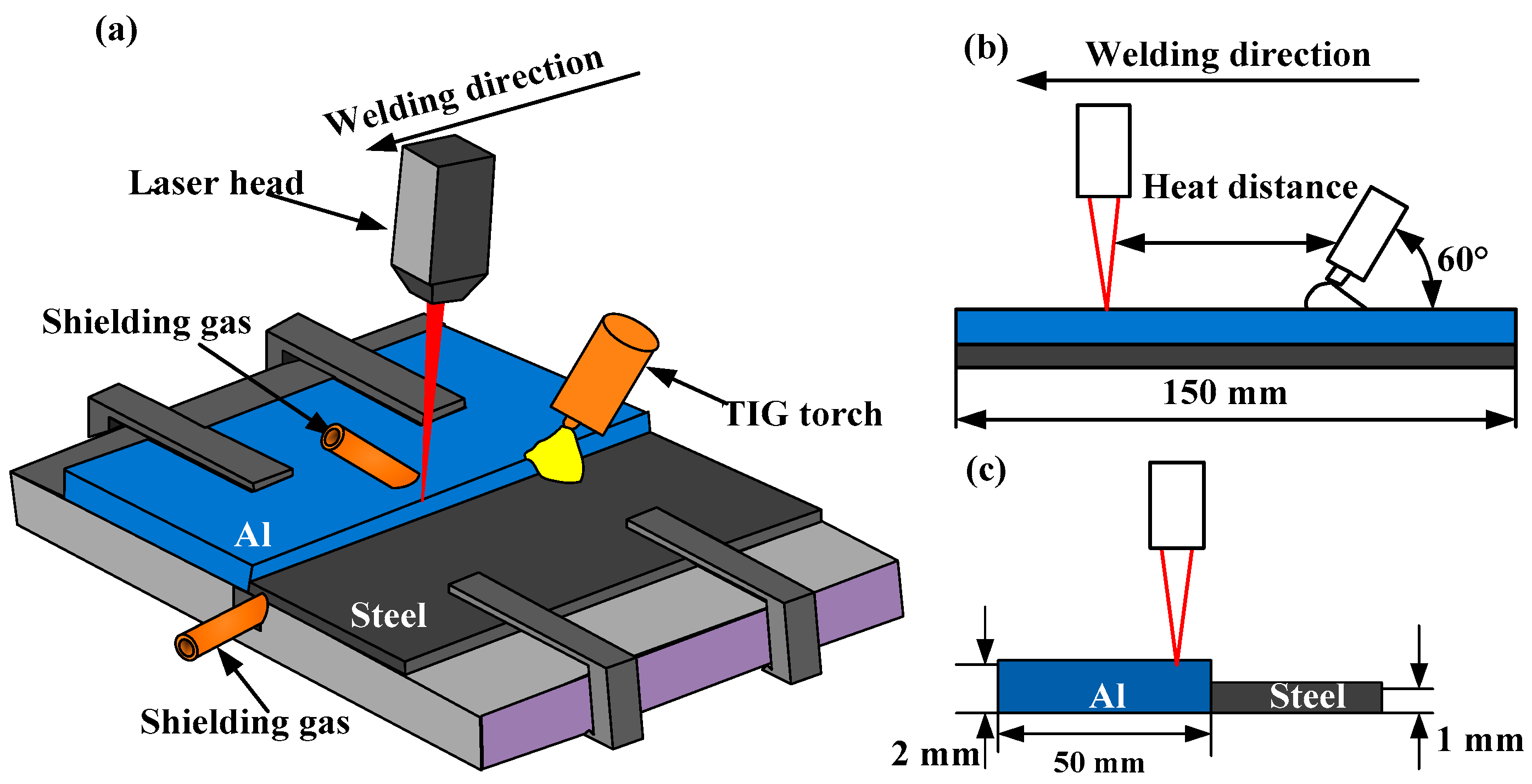
A high-power transverse flow CO2 laser equipment (GS-TFL-10K) (Wuhan Hans Goldensky laser system Co., Ltd., Wuhan, China) and an AC-TIG welder (TSP300) (Shenzhen Huayilong Electric Co., Ltd., Shenzhen, China) were used to join the Al alloy plate and the steel plate, in which the TIG welder provided the arc to assist the laser beam. The main parameters of CO2 laser equipment are as follows: the maximum output power of 10.0 KW, laser beam diameter is 0.4 mm. Before the welding, a mechanical grinding was used to remove the oxides layer on the surface of Aluminum plate, and the pre-placed powder and flux were mixed with acetone and then applied on the surface of the work-pieces. The aluminum plate and the galvanized steel plate were placed in the same horizontal plane and then fixed on the self-made welding fixture; the butt joint was adopted in this experiment. The welding schematic is shown in Figure 1.
During the welding process, argon was used to shield the molten pool from air; shielding gas flow rate was 10 L/min, welding speed kept unchanged at 10 mm/s, and the heat input can be expressed as: H = P/v + UI/v, where the p is laser power, U is the arc voltage, I is the arc current, and the v is the welding speed. The main welding parameters are listed in Table 3.
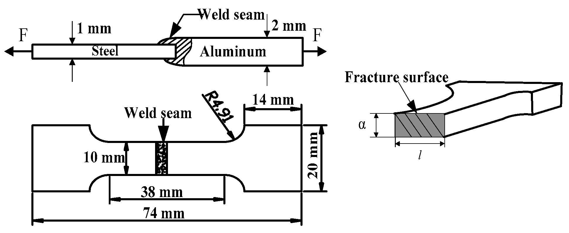
After the welding, the surface of the work-piece was lightly ground by an abrasive paper. Specimens for the microstructure analysis were cut from the Al-Steel weld joint; the surface of the specimens was mechanically ground and polished to have mirror-like quality. Microstructure and composition of the interfacial layer were identified using JSM-6701F scanning electron microscopy (SEM) (JEOL (BEIJING) CO., Ltd., Beijing, China) equipped with energy dispersive spectrometer (EDS) (JEOL (BEIJING) CO., Ltd., Beijing, China). The phase composition in the interfacial layer was identified by TN-570X X-ray diffraction (XRD) (Shimadzu (China) CO., Ltd., Beijing, China) using Cu–Kα radiation with step size of 0.02° and step time of 60 s. The tensile test was carried out at room temperature by the WDW-300J tensile testing machine (Nanjing OuChengjing Testing Equipment Co., Ltd., Nanjing, China). According to the weld joints strength test from the reference [21,22], we designed the tensile specimens as shown in Figure 2. The tensile strength can be calculated as:
here F is the maximum load, A is cross section area of fracture position, l is the width of tensile strength test sample (10 mm), α is the height of fracture surface. The height (α) and width (l) are measured using a Vernier caliper. The engineering strain is defined as ΔL/L0, where ΔL and L0 are the elongation length and initial lengths respectively.
2.3. Numerical Analysis of Temperature Field
A FEM analysis was used to calculate the temperature field. The flow of the molten pool was ignored in the calculation of the temperature distribution during welding.
The governing equation can be expressed by the following equation [23]
where ρ is the density of base material, μ, ν, and ω is fluid velocity in x, y, and z directions respectively, and φ is solving variables such as temperature, speed, etc. Γ is generalized diffusion coefficient, and s is source term such as mass source term, energy source term, and momentum source term.
The thermal boundary condition of the upper surface of work piece can satisfy the following formulations [24]:
here λ is thermal conductivity, hc is the heat transfer coefficient, β is the Boltzmann constant, ε is the radiation coefficient of surface, HV is latent heat of vaporization, qarc and qlaser represent the arc heat flux and laser heat flux which can be expressed by the following equations [25]:
For the front heat source:
For the rear heat source:
here η is the heat efficiency, U1 is welding voltage, I2 is the welding current, Q2 is laser power; af1, ar1, bh1, are arc heat source model parameters; af2, ar2, bh2 are laser heat source model parameters; v0 is heat source velocity.
3. Results and Discussion
3.1. Arc Effect on the Formation of Weld Seam
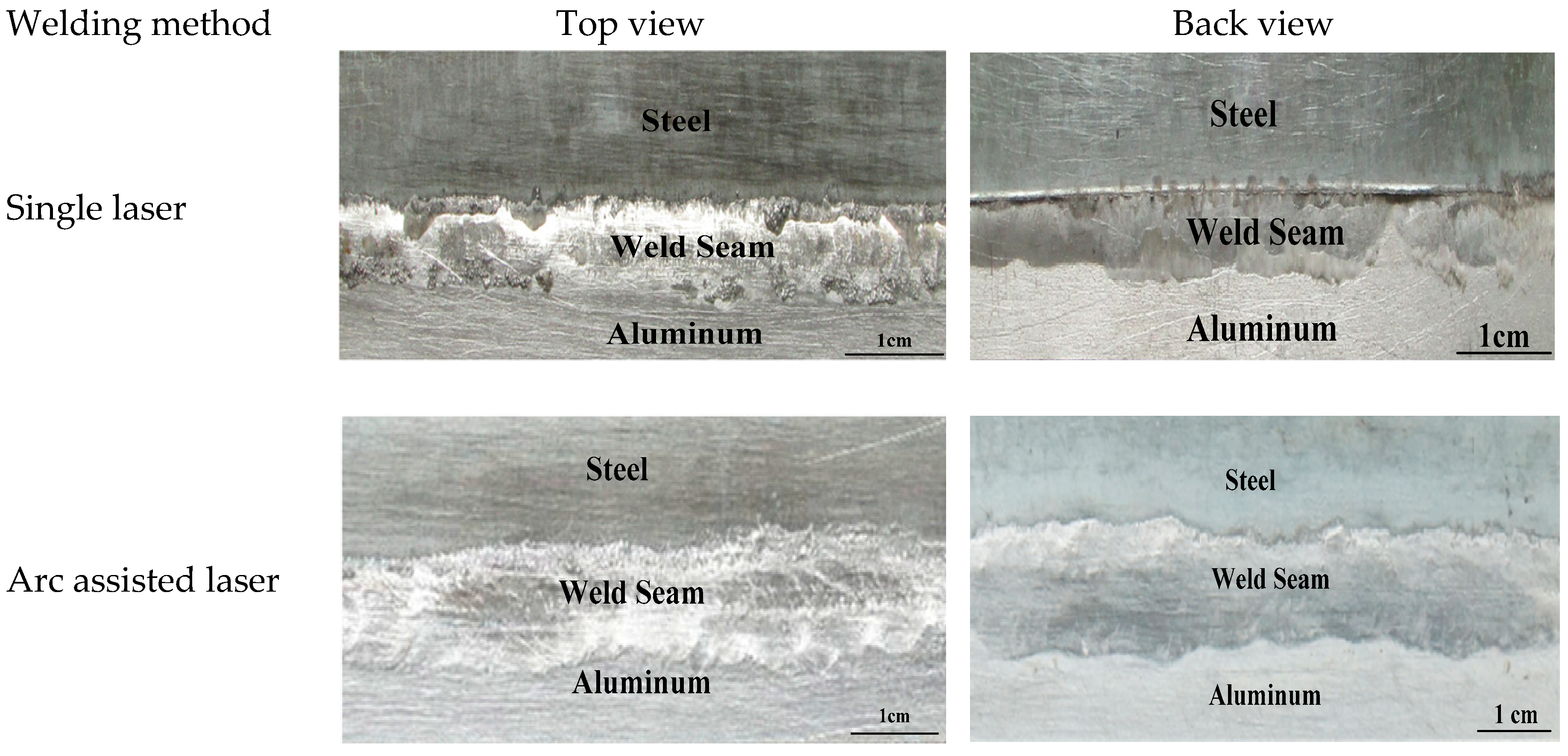
In the welding brazing process, the wetting and spreading behavior of Al molten pool on the steel surface determined the formation of weld seam [26]. In the present study, the weld seam morphology was mainly evaluated based on its continuity and back formation. Figure 3 shows the morphologies of top and back surfaces of the welding seams formed by single laser and arc assisted laser welding processes, respectively. Both the two methods can get continuous front formation of the weld seam, however, the back formation of arc assisted laser method exhibited a better wetting and spreading morphology than single laser welding brazing. This result suggests that assisted arc improves the wettability and fluidity of Al molten pool and helps the Al molten pool spread to the back surface of the steel plate.
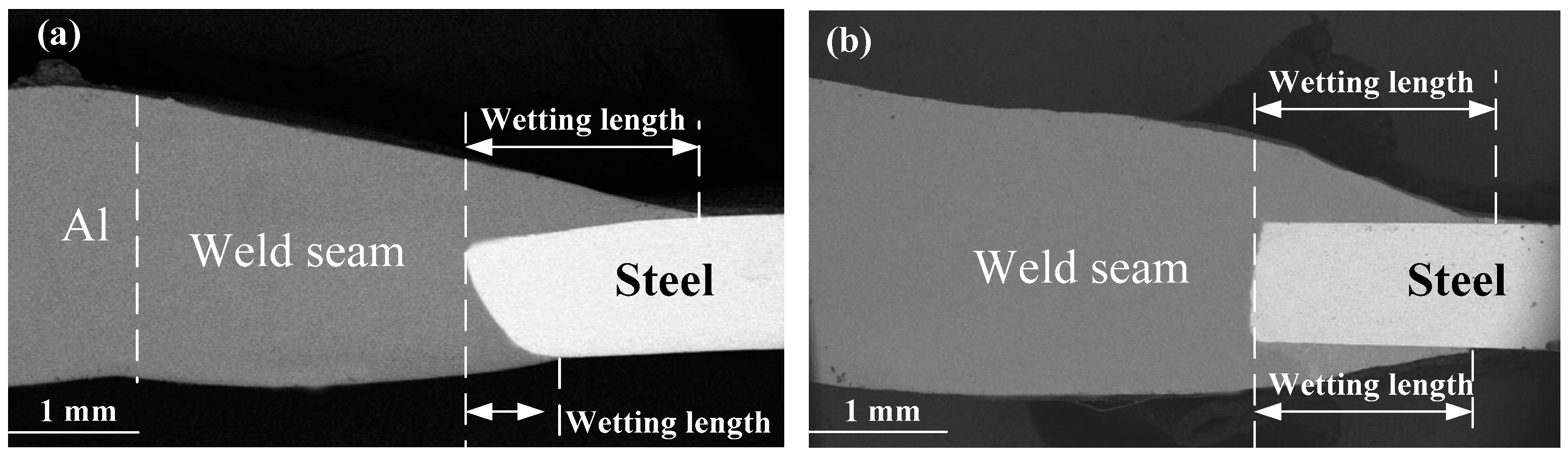
Figure 4 shows SEM images of the cross-sections of Al-steel butt joints formed by single laser and arc-assisted laser welding processes. The length of bottom wetting zone in arc assisted laser was about 2 mm, while it was 0.5 mm in single laser welding. In general, the welding seam produced by the arc assisted laser welding is better than that by the single laser welding. Especially, the wetting and spreading of back formation. Such trend is likely due to the arc-induced change of the heat conduction during the cooling (solidification) stage.
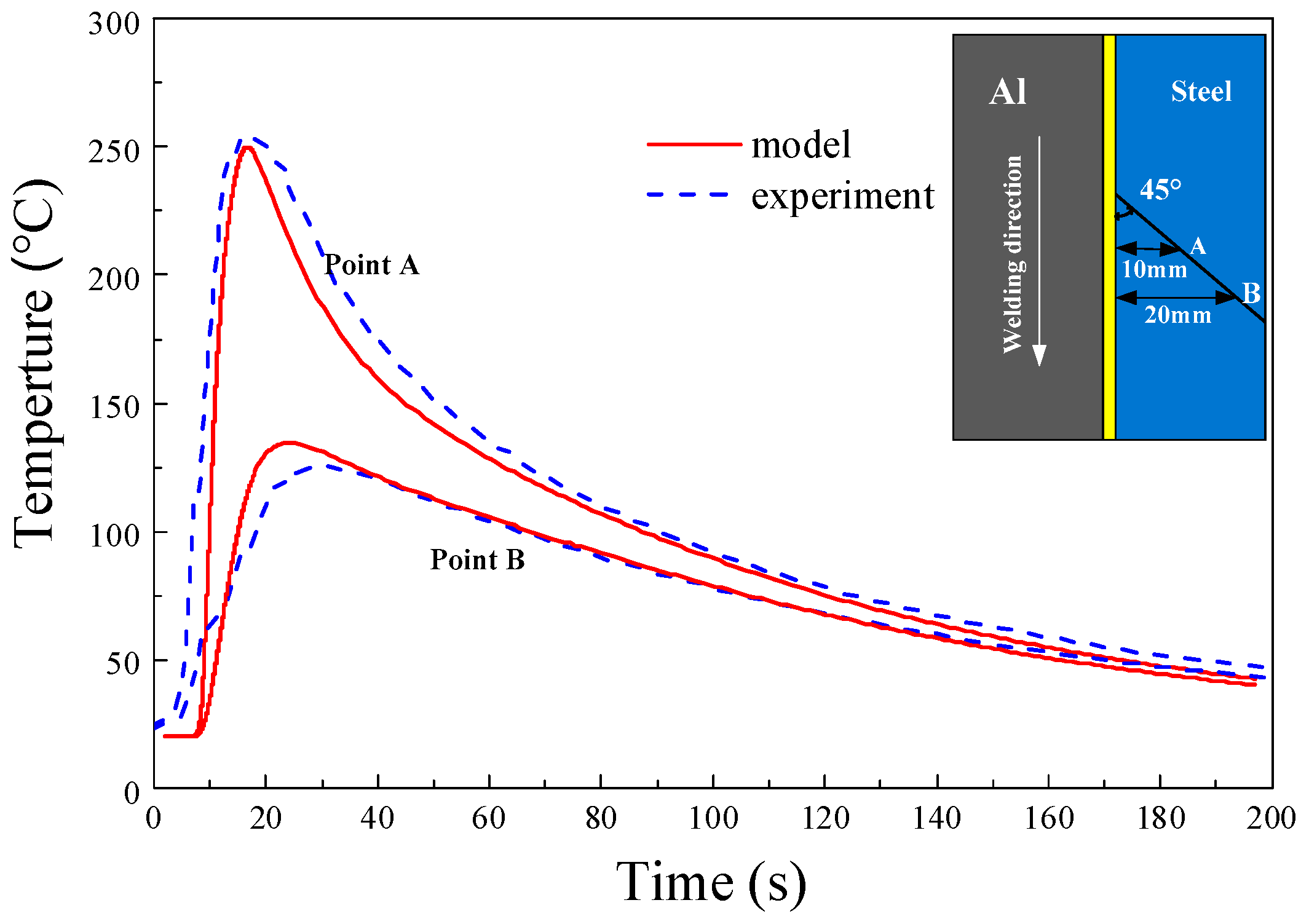
To understand the wetting and spreading behavior of motel pool, a FEM model of temperature field was established. Figure 5 displays the thermal cycles of point A and point B on the top surface of the steel, the thermal profiles calculated by the FEM at different positions were in good agreement with the experimentally measured values.
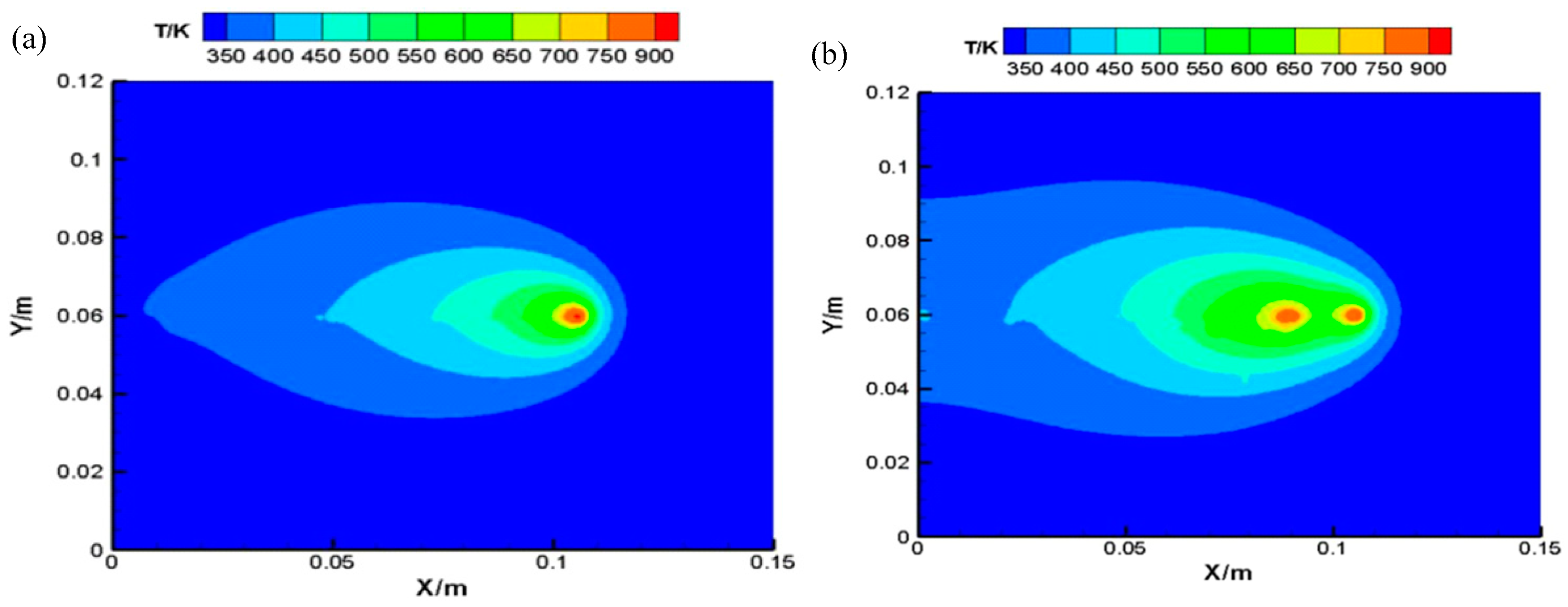
Figure 6 shows the temperature field of molten pool (X-Y plane) in the single laser and arc assisted laser welding process. As can be seen from Figure 6, the temperature field distribution of the molten pool under the action of a single laser and arc assisted laser is similar to the double ellipse distribution. The temperature distributions on both sides of aluminum/steel were asymmetric. As shown in Figure 6b, due to the addition of the assisted arc, the temperature field distribution of the base metal surface becomes larger than that in the single laser process, and the maximum temperature of the molten pool reaches 1002.54 K. The heat input from the arc can increase the spreading time of the molten metal in the welding pool, thus forming a better joint. Adding arc in the laser welding helps enhances the heat conduction, which allows the molten metal to have enough time to wet on the surfaces of the workpiece and to solidify in a little longer time.
3.2. Microstructures and Phase Identification of IMCs Layer
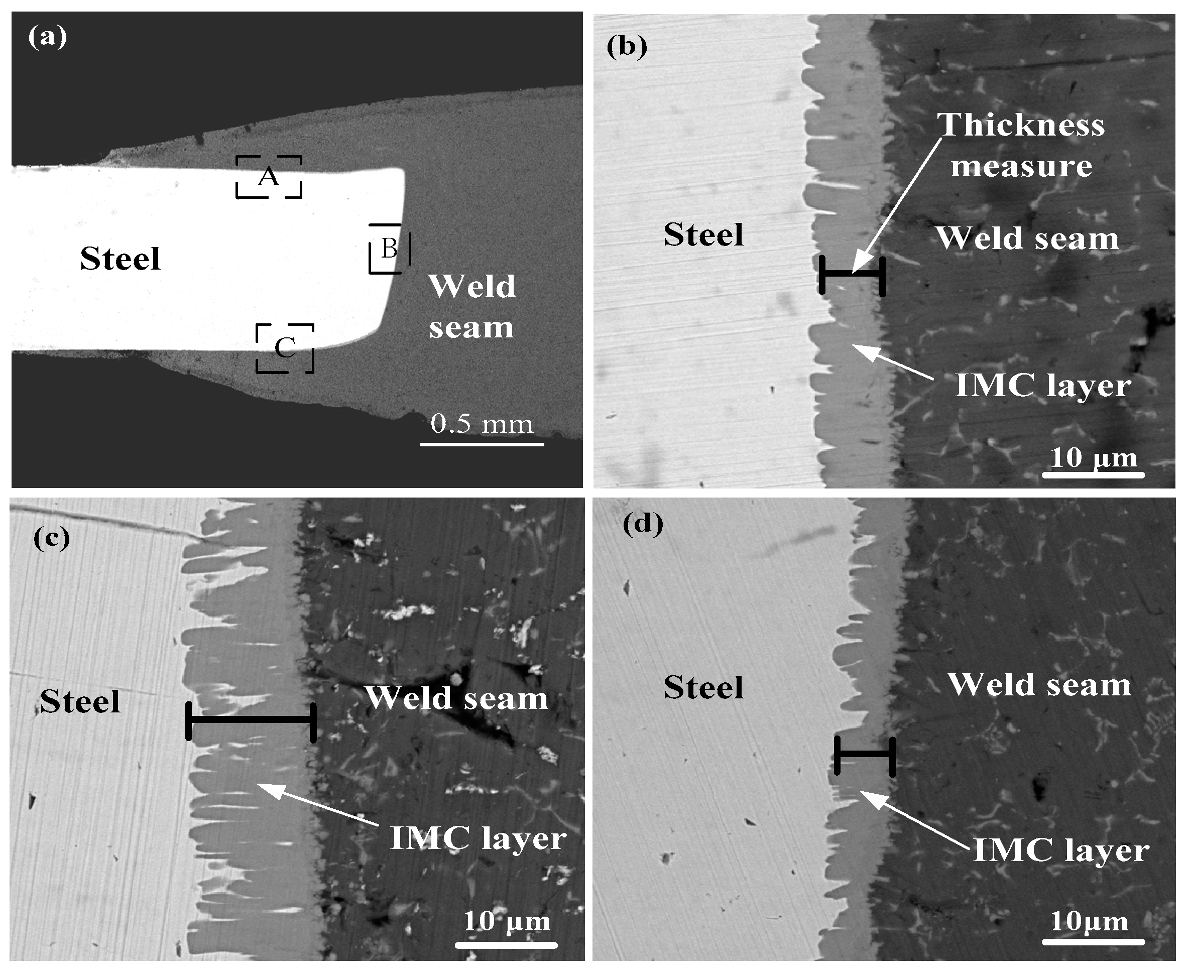
It is known that the structure and thickness of IMC layers play important roles in determining the mechanical behavior of welding joints [27]. A typical cross-section of weld joint was selected to observe the IMC layer. The specimen was obtained using the following process parameters: laser power of 1200 W, welding speed of 10 mm/s, heat distance of 15 mm, and arc current of 15 A.
Figure 7 shows the IMC layers formed at three spots of A, B, and C around a welding joint. One can easily observe the non-smooth interfaces of the IMC layer formed between the steel and the Al alloy weld seam. The thickness of the IMC layer changes with the location along the interfaces. For example, the average thickness of the IMC layer is 13 μm over the spot of B and 9 μm over the spot of C. In general, the IMC layer around the edge containing the spot B is thicker than those along the edges containing spots of A and C, since it takes more time for the completeness of solidification along the edge containing the spot B.
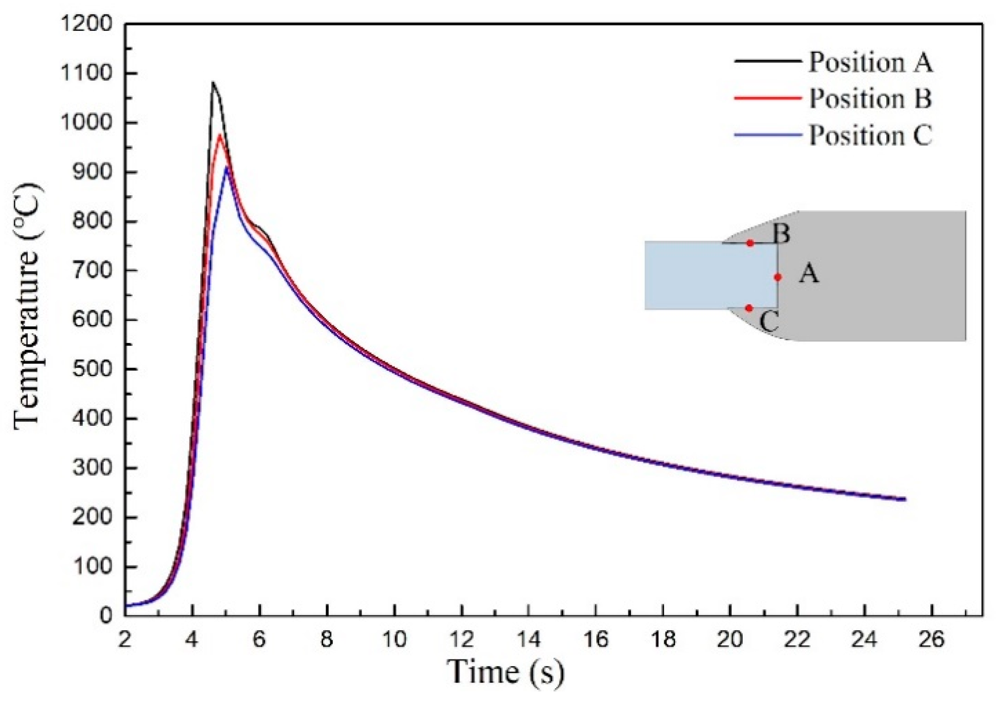
To better understand the thickness changes of IMC layer at the interface, the temperature profiles of three positions at the interface were obtained by FEM calculated model. Figure 8 shows temperature curves of interface obtained from calculated results at heat input of 1.2 KJ/cm. The liquid/solid reaction time of the three curves are essentially equal, but the peak temperatures from three positions are difference and the thickness of IMC layer becomes thick with the temperature increase. It indicated that the IMC thickness is mainly depended on the peak temperature.
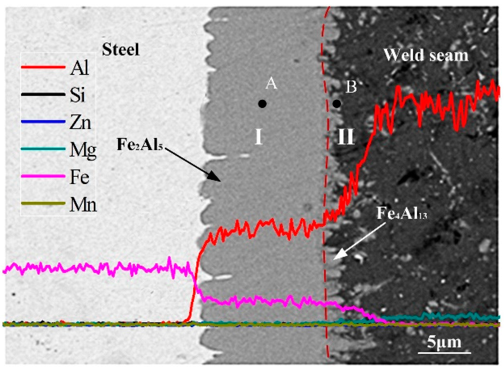
In order to identify the phase compositions of the IMC layer, an EDS line scanning analyses of the IMC layer was performed, as shown in Figure 9. It is evident that both Fe and Al uniformly distributed in the corresponding regions, i.e., the steel and the Al alloy, as expected, since no IMC can be observed in the steel matrix, and there are only a small amounts of IMC randomly distributed in the welding seam. According to the EDS pattern of the line scan, the IMC layer can be divided into two layers of I and II. In the layer I, both the fractions of Al and Fe remain relatively unchanged with the change of the distance to the steel/IMC interface. In the layer II, the fraction of Fe decreases with the decrease of the distance to the interface between the IMC layer and the welding seam, while the fraction of Al increases with the decrease of the distance to the IMC/weld seam interface. Such behavior suggests that the IMC in the layer I has different structure with that in the layer II. It is worth pointing out that there are little amounts of other elements presented in the IMC layers. The EDS point analysis of the IMCs was performed for the positions A and B as labeled in Figure 9, the atomic ratio of Al to Fe is in the range of 65/27 (~5:2) to 77/22 (~3:1), which suggests the formation of Fe2Al5 and Fe4Al13 IMC.
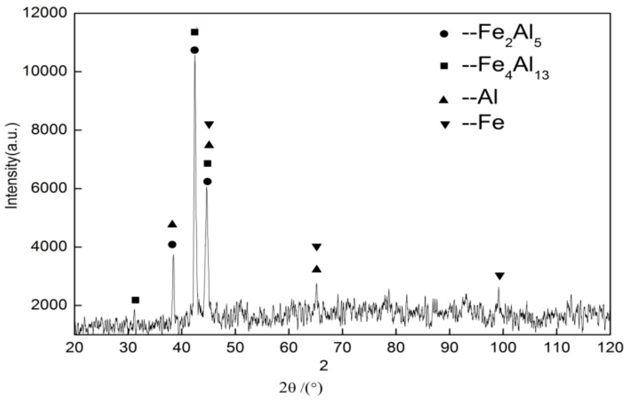
The XRD analysis results of fracture plane in steel side, as shown in Figure 10. The XRD results show that the reaction layer included two different kinds IMC: Fe4Al13 and Fe2Al5. According to Fe-Al equilibrium phase diagram [28], six non-stoichiometric IMC of Fe3Al, FeAl, FeAl2, Fe2Al3, Fe2Al5, and Fe4Al13 possibly form during reaction between iron and aluminum. Previous studies about the welding of aluminum alloy to steel indicated that the formed compound near welded seam was intermetallic compounds FeAl3 phase [29,30]. Van et al. [31] state that the η phase has two term name of “Fe4Al13” and “FeAl3”, while Fe4Al13 is more accurate expression. The IMC layer can be divided into two sublayers, as above analysis; one consists of Fe2Al5 IMC, and the other consists of Fe4Al13 IMC. The interface between the Fe2Al5 phase and the steel is presented in the needle-like shape, and the interface between the Fe4Al13 phase and the Al alloy is presented in the flocculent-like shape.
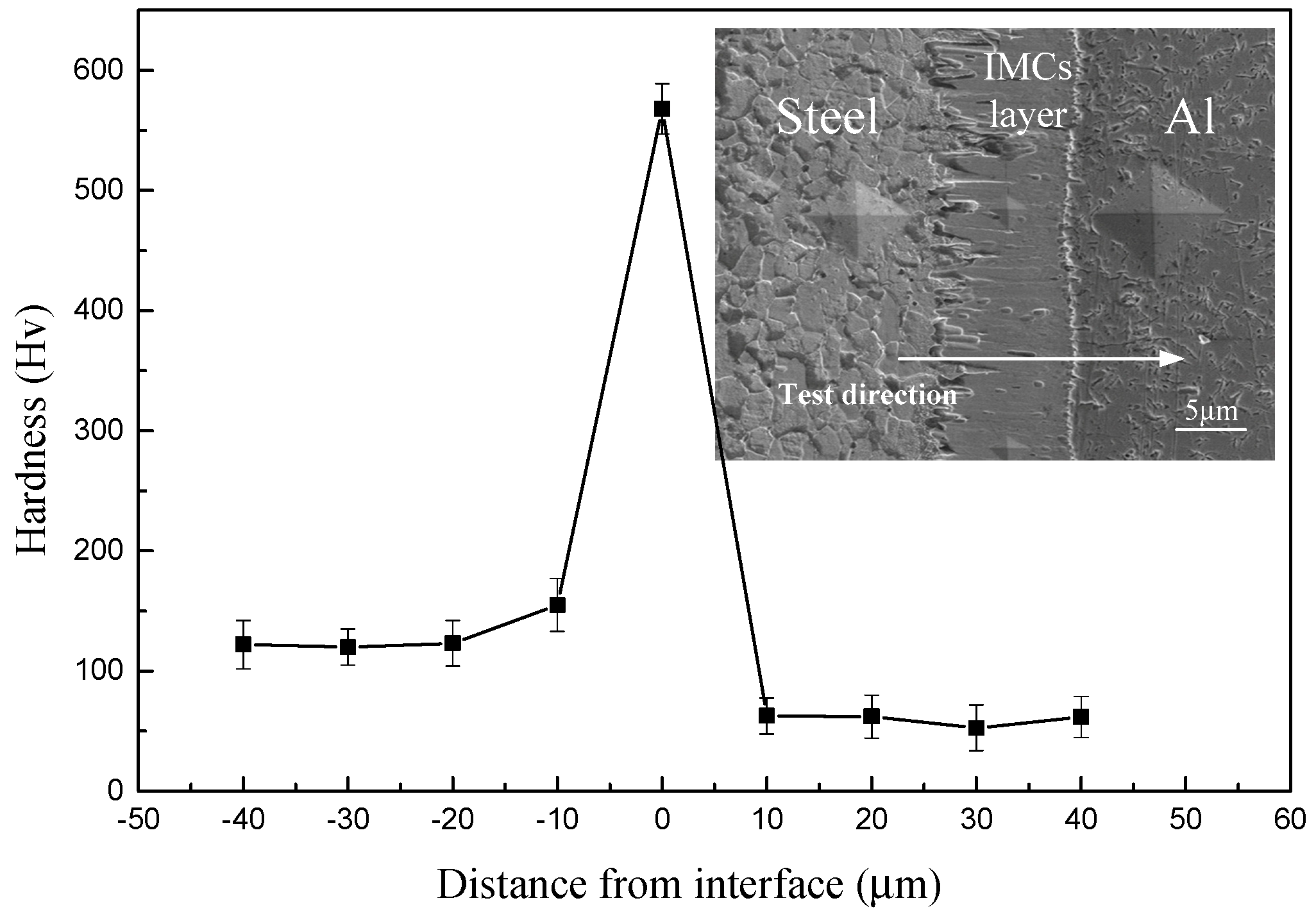
The hardness of the microstructure near the interface was measured by a Vickers indenter. Figure 11 shows the distribution of the Vickers hardness across the interface. The Al has the lowest Vickers hardness, as expected. It worth to point that the IMC layer has the highest Vickers hardness and the hardness of IMC is 5–6 times higher than the Al base metal. This result indicates that comparing to the base metals, the intermetallic compounds are more brittle and have large resistances to the penetration of an indenter onto the surface. The crack was easily generated in the IMC layer.
3.3. Mechanical Properties of Joints
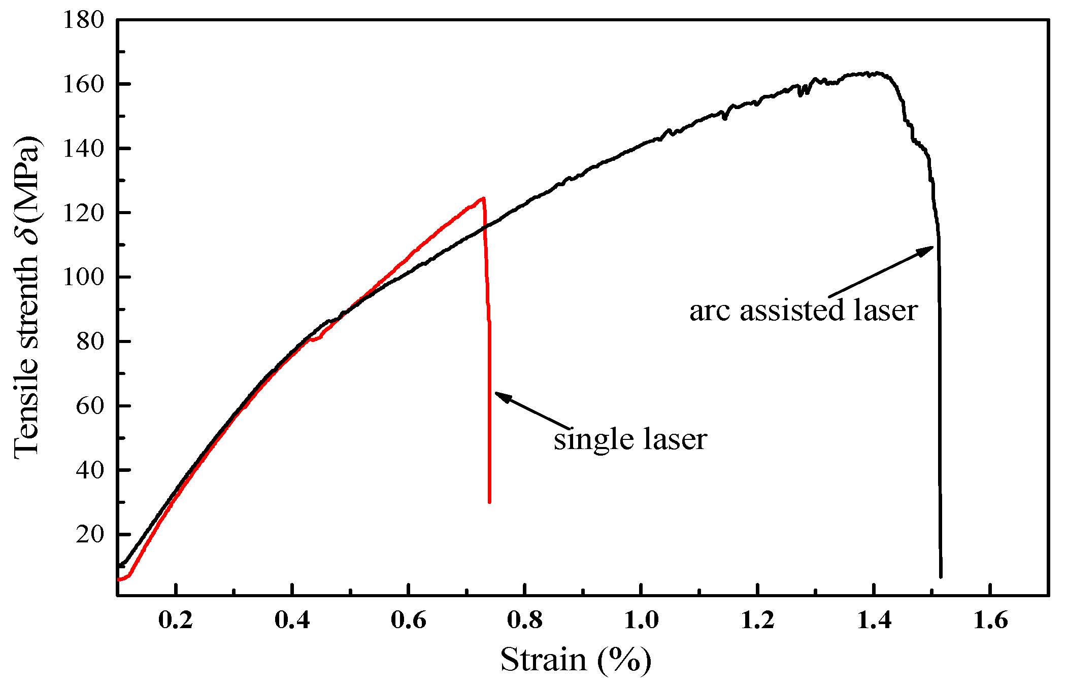
To compare the mechanical property between single laser welding and arc assisted laser welding, tensile tests of the tensile specimens were performed. Figure 12 shows the engineering stress-strain curves for the welded joint prepared by using single laser and arc assisted laser in the same welding parameters. The tensile strength value of the weld joint obtained by arc-assisted laser welding brazing was about 1.3 times than that in single laser welding brazing process. The highest value was near to 163 MPa, which almost 5A06 aluminum alloy strength for 74% (Under the same test conditions, the tensile strength of 5A06 aluminum alloy is 219 MPa), it indicates that the addition of arc can improve the tensile strength of aluminum/steel butt joint.
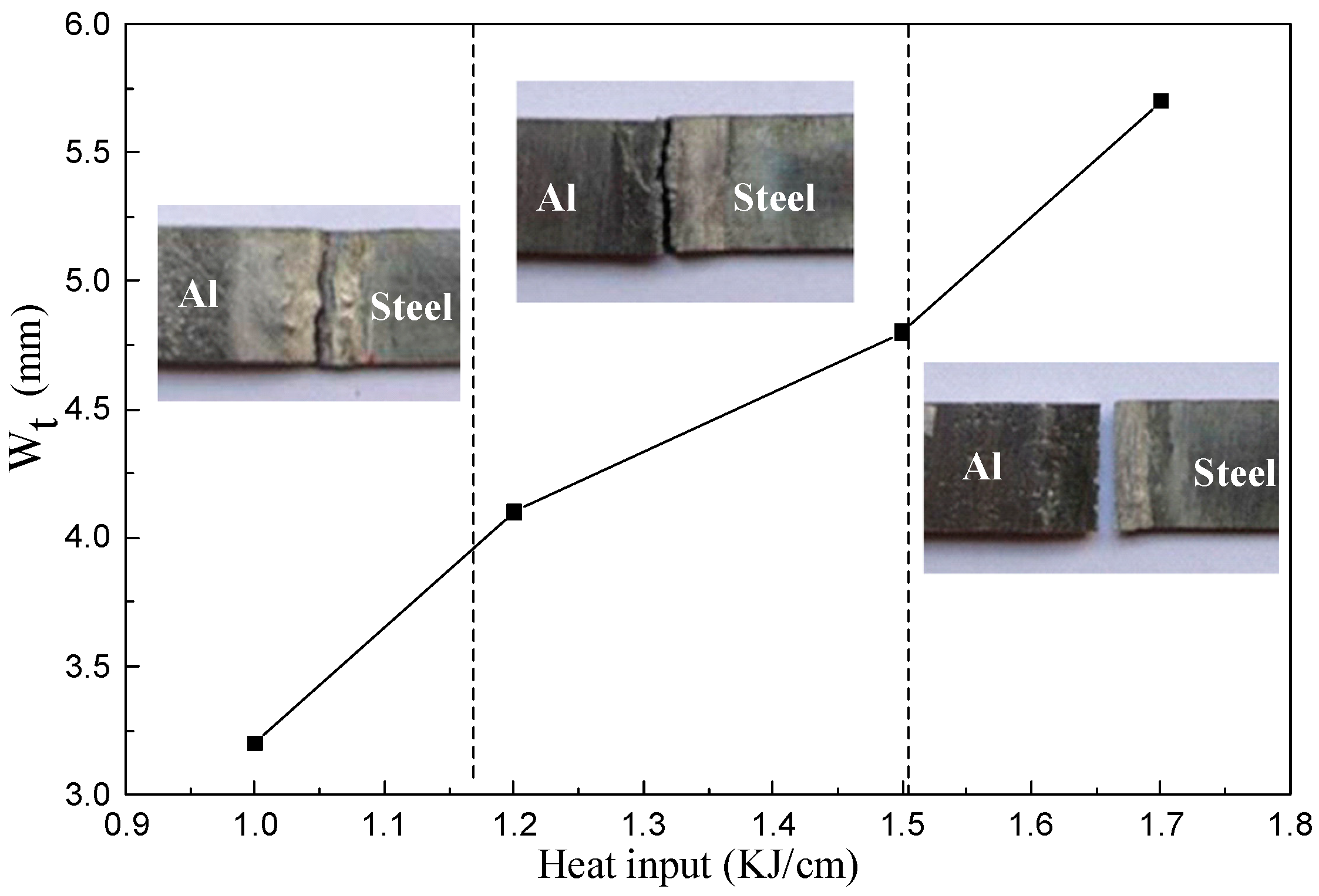
To understand the relationship between the wetting width and tensile strength, the fracture mode and wetting width under different welding heat input were analyzed. The total wetting width can be expressed:
here Wt is the total wetting width, Wb is the wetting width of back formation, and the Wf is the wetting width of front formation. Figure 13 shows the typical failure modes of joint that was obtained in different welding heat input for arc assisted laser welding. The total wetting width increase with the heat input increase. When the heat input was lower, the specimen was failure at the wetting and spreading zone due to the poor wetting ability of the weld pool. The highest tensile strength was 163 MPa when the weld joint failure at the weld seam. The worst case of tensile properties was fractured along the aluminum/steel interface with average tensile strength of 98 MPa when the total heat input exceeds 1.5 KJ/cm. In this case, the total width was about 5.7 mm, however, duo to the heat input was higher, the thickness of IMC exceeded permissible value (about 10 μm) [32] and the mechanical properties become worse. Note that a smooth edge morphology of fracture joint was appeared when the heat input exceeds 1.5 KJ/cm, it can be attributed to a brittle fracture caused by IMC layer. To improve the tensile strength of welded joints, one needs to limit the thickness of IMC.
Wt = Wb + Wf
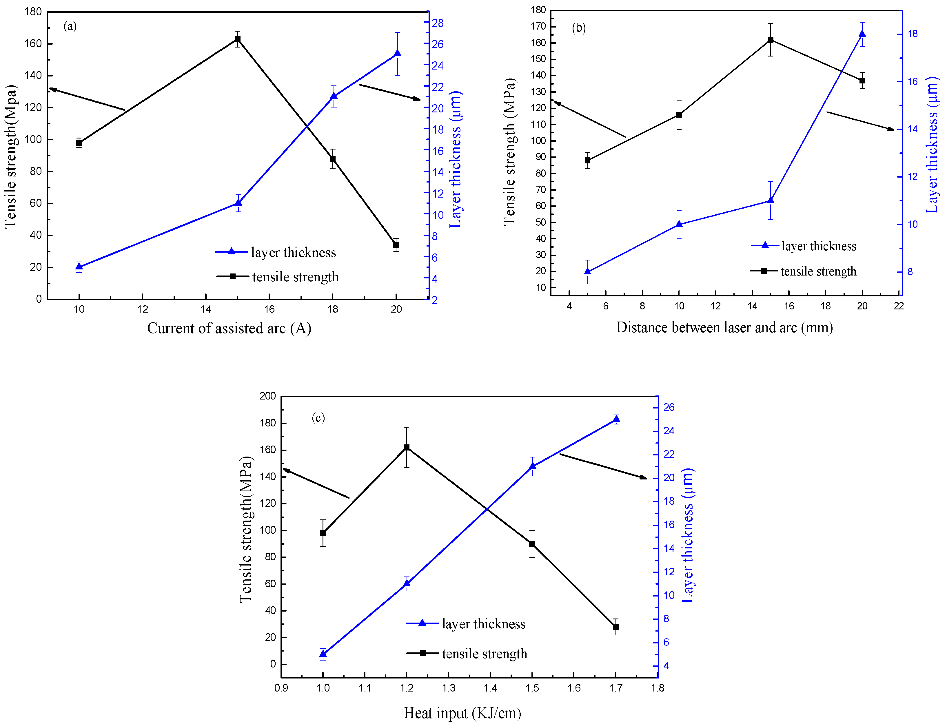
As discussed in introduction part, the IMC layer plays an important role in determining the structural durability of the structures consisting of welded joints. To examine the effect of the IMC layer (welded joints) on the Al/steel weld joint, tensile tests of the tensile specimens were performed. As the tensile strength and IMC were mainly affected by the heat source, we selected three main parameters (laser heat input, assisted arc current, and heat source distance) as variables. The tensile strength of the joint and the thickness of the IMC were measured under the same welding parameters. As shown in Figure 14, the thickness of the IMC increases linearly with the increase of the process parameters, while the tensile strength reaches certain value and then drops rapidly. This implied that due to the high heat input, the excessive growth of IMC layer led to the poor tensile strength of the joint. Therefore, in order to improve the strength of joint, it should control the heat input. The maximum tensile strength can reach 163 MPa When the IMC thickness between 8 μm and 12 μm. Tensile strength decreased rapidly when the thickness of the compound was more than 13 μm. Comparing Figure 14a,c to Figure 14b, Figure 14b had a more slowly decreasing trend in the process of tensile strength reduction. It indicates that the appropriate heat distance between laser and arc can improve tensile strength due to good weld appearance.
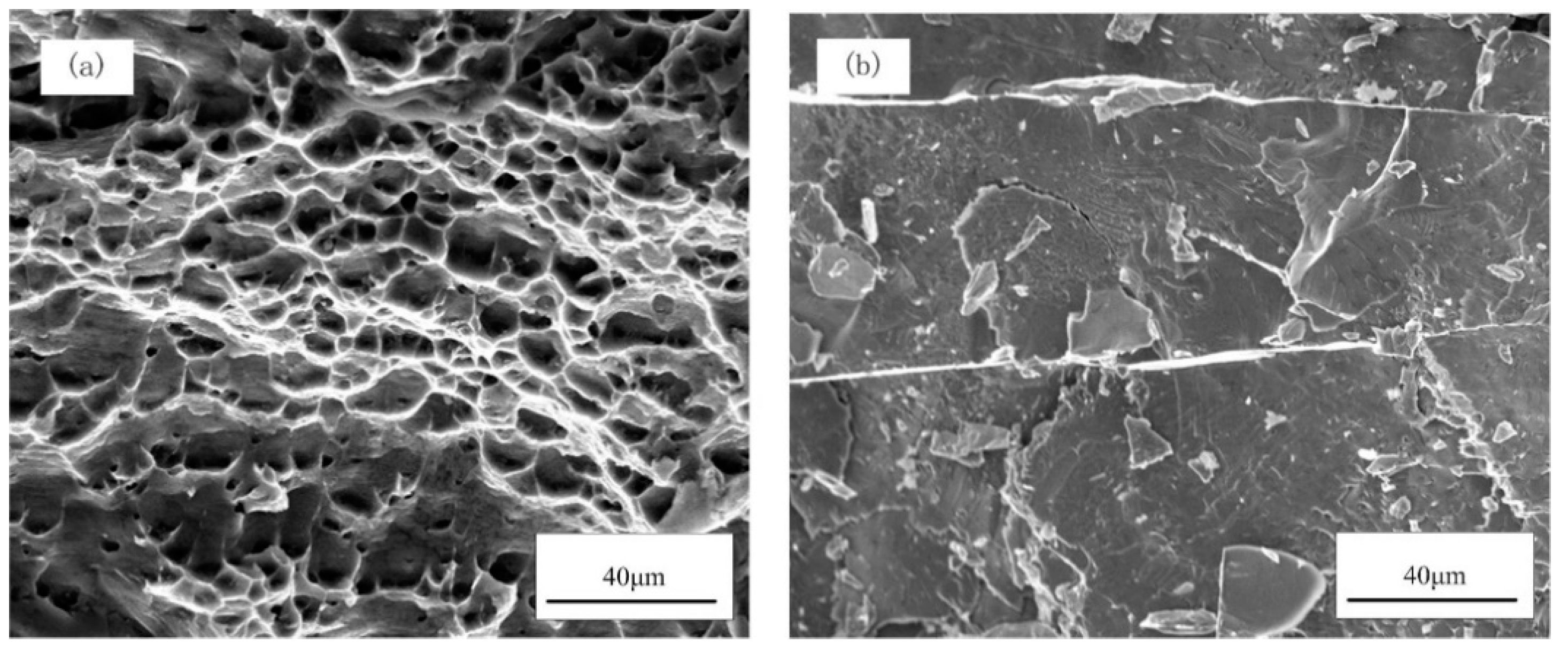
In order to further understand the fracture behavior of the arc assisted laser welding brazing tensile specimens, the fractured surfaces were observed by SEM, the typical fracture surface images were shown in Figure 15. As shown in Figure 15a, there are a large number of dimples in the fracture surface, and exhibited the typical ductile fracture when the fracture occurred at the weld seam of the aluminum alloy. Figure 15b shows the morphology of the tensile specimen detached along the IMC layer which exhibited brittle fracture pattern. As shown in Figure 15b, the fracture surface presented typical cleavage fracture with river pattern strips, it can be attributed to the lattice mismatch inside the IMC layer [33]. At a suitable heat input, the weld joint will fracture at the weld seam and shows a high tensile strength. On the other hand, a higher heat input will cause the excessive growth of the IMC layer, and the crack will generate at the IMC layer and rapidly propagate along the interface, which results in a poor tensile mechanical properties of the joint.
4. Conclusions
Dissimilar metals of 5A06 aluminum and galvanized steel were butt joined by arc assisted laser welding brazing technique. Major conclusions of this study could be summarized as followings:
- Using arc assisted laser welding brazing method, the galvanized steel was joined to the aluminum alloy with butt joint. In this welding process, a sound weld seam formation could be obtained on the back and front side, and the addition of arc could improve the wetting and spreading of weld pool and enhanced the tensile strength of weld joint.
- Compared to the single laser welding brazing method, the arc assisted laser welding brazing method had lager temperature distribution due to the addition of arc, the wetting width increased with the increasing of total heat input.
- Two different IMC phases were formed at the Al/steel interface, which was composed of Fe2Al5 near to the steel base metal and Fe4Al13 near to the aluminum welding brazing seam.
- There were there failure modes in tensile strength test: the wetting zone fracture, weld seam fracture, and Al/steel interface fracture. The maximum tensile strength of weld joint was 163 MPa, which was nearly 74% of 5A06 aluminum alloy when the fracture occurred at the weld seam.
Author Contributions
Conceptualization, D.F. and J.H.; methodology, X.Y.; formal analysis, Y.K.; data curation, X.Y. and C.L.; writing—original draft preparation, X.Y.; writing—review and editing, D.F.; supervision, D.F. and J.H.
Funding
This study was financially supported by the National Natural Science Foundation of China (No. 51465031).
Conflicts of Interest
The authors declare no conflict of interest.
References
- Liedl, G.; Bielak, R.; Ivanova, J.; Enzinger, N.; Figner, G.; Bruckner, J.; Pasice, H.; Pudar, M.; Hampel, S. Joining of Aluminum and Steel in Car Body Manufacturing. Phys. Procedia 2011, 12, 150–156. [Google Scholar] [CrossRef] [Green Version]
- Kouadri-David, A.; PSM Team. Study of metallurgic and mechanical properties of laser welded heterogeneous joints between DP600 galvanized steel and aluminum. Mater. Des. 2014, 54, 184–195. [Google Scholar] [CrossRef]
- Wang, P.; Chen, X.; Pan, Q.; Madigan, B.; Long, J. Laser welding dissimilar materials of aluminum to steel: An overview. Int. J. Adv. Manuf. Technol. 2016, 87, 3081–3090. [Google Scholar] [CrossRef]
- Li, L.; Xia, H.; Tan, C.; Ma, N. Influence of laser power on interfacial microstructure and mechanical properties of laser welded-brazed Al/steel dissimilar butted joint. J. Manuf. Process. 2018, 32, 160–174. [Google Scholar] [CrossRef]
- Meco, S.; Pardal, G.; Ganguly, S.; Williams, S.; Mcpherson, N. Application of laser in seam welding of dissimilar steel to aluminum joints for thick structural components. Opt. Lasers Eng. 2015, 67, 22–30. [Google Scholar] [CrossRef]
- Liu, J.; Jiang, S.; Shi, Y.; Kuang, Y.; Huang, G.; Zhang, H. Laser fusion–brazing of aluminum alloy to galvanized steel with pure Al filler powder. Opt. Laser Technol. 2015, 66, 1–8. [Google Scholar] [CrossRef]
- Zhang, H.T.; Feng, J.C.; He, P. Interfacial phenomena of cold metal transfer (CMT) welding of zinc coated steel and wrought aluminum. Mater. Sci. Technol. 2008, 24, 1346–1349. [Google Scholar] [CrossRef]
- Kang, M.; Kim, C. Joining Al 5052 alloy to aluminized steel sheet using cold metal transfer process. Mater. Des. 2015, 81, 95–103. [Google Scholar] [CrossRef]
- Yang, S.; Zhang, J.; Lian, J.; Lei, Y. Welding of aluminum alloy to zinc coated steel by cold metal transfer. Mater. Des. 2013, 49, 602–612. [Google Scholar] [CrossRef]
- Dong, H.; Yang, L.; Dong, C.; Kou, S. Improving arc joining of Al to steel and Al to stainless steel. Mater. Sci. Eng. A 2012, 534, 424–435. [Google Scholar] [CrossRef]
- Yagati, K.P.; Bathe, R.N.; Rajulapati, K.V.; Rao, K.B.S.; Padmanabham, G. Fluxless arc weld-brazing of aluminium alloy to steel. J. Mater. Process. Technol. 2014, 214, 2949–2959. [Google Scholar] [CrossRef]
- Martinsen, K.; Hu, S.J.; Carlson, B.E. Joining of dissimilar materials. CIRP Ann.-Manuf. Technol. 2015, 64, 679–699. [Google Scholar] [CrossRef] [Green Version]
- Qiu, R.; Satonaka, S.; Iwamoto, C. Effect of interfacial reaction layer continuity on the tensile strength of resistance spot welded joints between aluminum alloy and steels. Mater. Des. 2009, 30, 3686–3689. [Google Scholar] [CrossRef]
- Kashani, H.T.; Kah, P.; Martikainen, J. Laser Overlap Welding of Zinc-coated Steel on Aluminum Alloy. Phys. Procedia 2015, 78, 265–271. [Google Scholar] [CrossRef] [Green Version]
- Dharmendra, C.; Rao, K.P.; Wilden, J.; Reich, S. Study on laser welding–brazing of zinc coated steel to aluminum alloy with a zinc based filler. Mater. Sci. Eng. A 2011, 528, 1497–1503. [Google Scholar] [CrossRef]
- Laukant, H.; Wallmann, C.; Korte, M.; Glatzel, U. Flux-less joining technique of aluminum with zinc-coated steel sheets by a dual-spot-laser beam. Adv. Mater. Res. 2005, 6, 163–170. [Google Scholar] [CrossRef]
- Alexandre, M. Dissimilar material joining using laser (aluminum to steel using zinc-based filler wire). Opt. Laser Technol. 2007, 39, 652–661. [Google Scholar] [CrossRef]
- Sun, J.; Yan, Q.; Gao, W.; Huang, J. Investigation of laser welding on butt joints of Al/steel dissimilar materials. Mater. Des. 2015, 83, 120–128. [Google Scholar] [CrossRef]
- Shahverdi, H.R.; Ghomashchi, M.R.; Shabestari, S.; Hejazi, J. Microstructure alanalysis of interfacial reaction between molten aluminium and solid iron. J. Mater. Process. Technol. 2002, 124, 345–352. [Google Scholar] [CrossRef]
- Zhang, M.; Chen, G.; Zhang, Y.; Wu, K. Research on microstructure and mechanical properties of laser keyhole welding–brazing of automotive galvanized steel to aluminum alloy. Mater. Des. 2013, 45, 24–30. [Google Scholar] [CrossRef]
- Zhang, Y.; Li, F.; Guo, G.; Wang, G.; Wei, H. Effects of different powders on the micro-gap laser welding-brazing of an aluminium-steel butt joint using a coaxial feeding method. Mater. Des. 2016, 109, 10–18. [Google Scholar] [CrossRef]
- Cao, R.; Yu, G.; Chen, J.H.; Wang, P.C. Cold metal transfer joining aluminum alloy-to-galvanized mild steel. J. Mater. Process. Technol. 2013, 213, 1753–1763. [Google Scholar] [CrossRef]
- Wang, R.; Lei, Y.; Shi, Y. Numerical simulation of transient temperature field during laser keyhole welding of 304 stainless steel sheet. Opt. Laser Technol. 2011, 43, 870–873. [Google Scholar] [CrossRef]
- Cho, D.W.; Cho, W.I.; Na, S.J. Modeling and simulation of arc: Laser and hybrid welding process. J. Manuf. Process. 2014, 16, 26–55. [Google Scholar] [CrossRef]
- Meng, X.; Qin, G.; Su, Y.; Fu, B.; Ji, Y. Numerical simulation of large spot laser + MIG arc brazing–fusion welding of Al alloy to galvanized steel. J. Mater. Process. Technol. 2015, 222, 307–314. [Google Scholar] [CrossRef]
- Gatzen, M.; Radel, T.; Thomy, C.; Vollertsen, F. Wetting and solidification characteristics of aluminium on zinc coated steel in laser welding and brazing. J. Mater. Process. Technol. 2016, 238, 352–360. [Google Scholar] [CrossRef]
- Sun, J.; Huang, J.; Yan, Q.; Li, Z. Fiber laser butt joining of aluminum to steel using welding-brazing method. Int. J. Adv. Manuf. Technol. 2016, 85, 2639–2650. [Google Scholar] [CrossRef]
- Kattner, U.R. Binary Alloy Phase Diagrams; ASM International: Materials Park, OH, USA, 1990. [Google Scholar]
- Meco, S.; Ganguly, S.; Williams, S.; McPherson, N. Effect of laser processing parameters on the formation of intermetallic compounds in fe-al dissimilar welding. J. Mater. Eng. Perform. 2014, 23, 3361–3370. [Google Scholar] [CrossRef]
- Reisgen, U.; Otten, C.; Schönberger, J. Investigations about the influence of the time–temperature curve on the formation of intermetallic phases during electron beam welding of steel–aluminium material combinations. Weld. World 2014, 58, 443–454. [Google Scholar] [CrossRef]
- Van Alboom, A.; Lemmens, B.; Breitbach, B.; De Grave, E.; Cottenier, S.; Verbeken, K. Multi-method identification and characterization of the intermetallic surface layers of hot-dip Al-coated steel: FeAl3, or Fe4Al13, and Fe2Al5, or Fe2Al5+x. Surf. Coat. Technol. 2017, 324, 419–428. [Google Scholar] [CrossRef]
- Song, J.; Lin, S.; Yang, C.; Fan, C. Effects of Si additions on intermetallic compound layer of aluminum–steel TIG welding–brazing joint. J. Alloys Compd. 2009, 488, 217–222. [Google Scholar] [CrossRef]
- Xia, H.; Tan, C.; Li, L.; Ma, N. In Situ SEM Observations of Fracture Behavior of Laser Welded–Brazed Al/Steel Dissimilar Joint. J. Mater. Eng. Perform. 2018, 27, 1047–1057. [Google Scholar] [CrossRef]
Figure 1.
Schematic diagram of the arc-assisted laser welding; (a) overview, (b) front view, and (c) side view.
Figure 1.
Schematic diagram of the arc-assisted laser welding; (a) overview, (b) front view, and (c) side view.

Figure 2.
The geometry of tensile specimens and fracture surface.

Figure 3.
Surface morphologies of the weld seams formed by single laser and arc assisted laser welding processes.
Figure 3.
Surface morphologies of the weld seams formed by single laser and arc assisted laser welding processes.

Figure 4.
SEM images of the cross-sections of Al-steel butt joints formed by two different welding processes; (a) single laser welding brazing, and (b) arc assisted laser welding brazing
Figure 4.
SEM images of the cross-sections of Al-steel butt joints formed by two different welding processes; (a) single laser welding brazing, and (b) arc assisted laser welding brazing

Figure 5.
Comparison between experimental and calculated thermal cycles.

Figure 6.
The temperature field of molten pool: (a) single laser welding brazing process, and (b) arc assisted laser welding brazing.
Figure 6.
The temperature field of molten pool: (a) single laser welding brazing process, and (b) arc assisted laser welding brazing.

Figure 7.
SEM images of the intermetallic compounds IMC layers at different locations of the Al-steel joint; (a) overview of the joint, (b) the IMC layer around the spot A, (c) the IMC layer around the spot B, and (d) the IMC layer around the spot C.
Figure 7.
SEM images of the intermetallic compounds IMC layers at different locations of the Al-steel joint; (a) overview of the joint, (b) the IMC layer around the spot A, (c) the IMC layer around the spot B, and (d) the IMC layer around the spot C.

Figure 8.
Temperature profiles of different positions at Al/Steel interface.

Figure 9.
SEM images of the Al/Fe interface and the corresponding EDS pattern of the line scan.

Figure 10.
XRD patterns of the fractured surface on the steel substrate.

Figure 11.
Distribution of Vickers hardness across the interface.

Figure 12.
Engineering stress engineering strain curves of single laser welding and arc assisted laser welding.
Figure 12.
Engineering stress engineering strain curves of single laser welding and arc assisted laser welding.

Figure 13.
Fracture modes of the weld joints in different welding heat input.

Figure 14.
Effects of welding parameters on the IMC layer thickness and the tensile strength of the butt joint: (a) effects of assisted arc current, (b) effects of distance between heat source, (c) effects of heat input.
Figure 14.
Effects of welding parameters on the IMC layer thickness and the tensile strength of the butt joint: (a) effects of assisted arc current, (b) effects of distance between heat source, (c) effects of heat input.

Figure 15.
SEM fractography of the ruptured specimens: (a) fractured at weld seam, (b) detached between galvanized steel and brazed seam interface.
Figure 15.
SEM fractography of the ruptured specimens: (a) fractured at weld seam, (b) detached between galvanized steel and brazed seam interface.


Table 1.
Chemical compositions of ST04Z galvanized steel (wt. %).
| Mn | Si | P | S | Cu | Zn | C | Ni | Fe |
|---|---|---|---|---|---|---|---|---|
| 0.4 | ≤0.40 | 0.02 | ≤0.30 | ≤0.15 | ≤0.15 | 0.08 | ≤0.15 | Bal. |
Table 2.
Chemical composition of 5A06 aluminum alloy (wt. %).
| Mg | Si | Mn | Ti | Cu | Zn | Fe | Al |
|---|---|---|---|---|---|---|---|
| 5.8–6.8 | 0.4 | 0.5–0.8 | 0.02–0.10 | 0.1 | 0.20 | 0.4 | Bal. |
Table 3.
The main parameters of arc assisted laser welding-brazing.
| Heat Input (KJ/cm) | Arc Current (A) | Heat Distance (mm) |
|---|---|---|
| 1.0 | 15 | 15 |
| 1.2 | 15 | 15 |
| 1.5 | 15 | 15 |
| 1.7 | 15 | 15 |
| 1.2 | 10 | 15 |
| 1.2 | 15 | 15 |
| 1.2 | 18 | 15 |
| 1.2 | 20 | 15 |
| 1.2 | 15 | 5 |
| 1.2 | 15 | 10 |
| 1.2 | 15 | 15 |
| 1.2 | 15 | 20 |
© 2019 by the authors. Licensee MDPI, Basel, Switzerland. This article is an open access article distributed under the terms and conditions of the Creative Commons Attribution (CC BY) license (http://creativecommons.org/licenses/by/4.0/).
Share and Cite
MDPI and ACS Style
Yu, X.; Fan, D.; Huang, J.; Li, C.; Kang, Y. Arc-Assisted Laser Welding Brazing of Aluminum to Steel. Metals 2019, 9, 397. https://doi.org/10.3390/met9040397
AMA Style
Yu X, Fan D, Huang J, Li C, Kang Y. Arc-Assisted Laser Welding Brazing of Aluminum to Steel. Metals. 2019; 9(4):397. https://doi.org/10.3390/met9040397
Chicago/Turabian StyleYu, Xiaoquan, Ding Fan, Jiankang Huang, Chunling Li, and Yutao Kang. 2019. "Arc-Assisted Laser Welding Brazing of Aluminum to Steel" Metals 9, no. 4: 397. https://doi.org/10.3390/met9040397
Note that from the first issue of 2016, this journal uses article numbers instead of page numbers. See further details here.