Resistance Spot Welding of Aluminum Alloy and Carbon Steel with Spooling Process Tapes


Department of Mechanical Engineering, Hanyang University, Seoul 133-791, Korea
*
Author to whom correspondence should be addressed.
Metals 2019, 9(4), 410; https://doi.org/10.3390/met9040410
Submission received: 10 March 2019
/
Revised: 29 March 2019
/
Accepted: 1 April 2019
/
Published: 3 April 2019
(This article belongs to the Special Issue Dissimilar Metal Welding)
Abstract
:Many lightweight materials, including aluminum alloy, magnesium alloy, and plastic, have been used for automotives. Aluminum alloy—the most commonly utilized lightweight metal—has poor resistance spot weldability owing to its inherent properties, which demand the development of welding solutions. Various welding techniques are utilized to improve the resistance spot weldability of aluminum alloy, including DeltaSpot welding. However, the technological development for welding dissimilar metals (aluminum alloy and steel) required for vehicle body assembly is still in its nascent stages. This study proposes DeltaSpot welding (a resistance spot welding process with spooling process tapes) using the alloy combination of 6000 series aluminum alloy (Al 6K32) and 440 MPa grade steel (SGARC 440). The welding characteristics of the main process parameters in DeltaSpot welding were analyzed and the weldability of the combination of the aluminum alloy, Al 6K32, and 440 MPa grade steel was evaluated. In addition, the characteristics of the intermetallic compound layer between the 440 MPa grade steel and Al 6K32 sheets were identified via scanning electron microscopy/energy dispersive X-ray spectroscopy (SEM-EDS).
1. Introduction
The automotive industry has recently invested intensive and extensive research and development efforts to apply lightweight materials, such as high-strength steel, plastic, aluminum alloy, and magnesium alloy, to vehicle body structures for various purposes; for example, to reduce greenhouse gas and exhaust emissions to satisfy increasingly rigorous environmental regulations, to improve fuel efficiency in the face of rising oil prices due to energy resource depletion, to provide electronic equipment for user convenience, and to ensure durability and safety [1,2,3,4,5,6,7,8,9,10]. Aluminum, in particular, is about one-third the weight of steel and has excellent shock absorption, high specific strength, and high corrosion resistance owing to the passivity layer formed on the surface, and studies have attempted to apply it to vehicle body structures [11,12]. Aluminum alloys applied to vehicle body structures can be joined by several methods in mechanical joining, such as resistance spot welding (RSW), self-piercing rivet, friction stir welding, clinching, and adhesive spraying [13,14,15,16,17,18,19,20]. In the case of RSW, however, when copper (as an electrode material) is alloyed with aluminum alloy by RSW, the electrode is prone to contamination and a short service life, necessitating frequent electrode dressing. Furthermore, it is difficult to ensure resistance spot weldability owing to the low resistivity and high thermal expansion coefficient of aluminum. These aluminum-specific properties of high electrical and thermal conductivities make it a considerable challenge to secure appropriate RSW conditions for aluminum alloy. In general, welding is performed by applying a high heat input and short welding time. The oxide film formed on the surface of aluminum alloy causes welding defects, such as voids and cracks, in the joints [21,22,23,24,25,26].
Numerous studies have been conducted on the RSW of aluminum alloys. For instance, Thornton et al. studied the effects of the weld nugget diameter and the quality on weld strength in terms of the fatigue life of the joint in RSW [27]. Sun et al. examined the contact area change pattern and nugget formation process, focusing on the interfacial contact behavior during welding [28]. Senkara et al. analyzed the crack formation mechanism to investigate the causes of cracking in RSW and the effect of cracking on weld strength [29]. Subsequently, Browne et al. determined the process parameters influencing nugget formation during welding by performing a simulation considering electrical, thermal, and mechanical processes [30], and they presented the contact resistance values that facilitate RSW by analyzing the effect of the contact resistance on the base metal and estimating the contact resistance based on shunt resistance [31]. In their studies on RSW joining of two dissimilar metals, Qiu et al. examined the relationship between the thickness of the intermetallic compound (IMC) layer and the weld strength between aluminum alloy and steel [32], and the relationship between the IMC layer and weld zone location as well as welding current and material combination during the RSW of dissimilar metals using a cover plate [33]. Mortazavi et al. analyzed the fracture shape and IMC layer formation according to the welding current, as well as the failure modes and IMC layer formation depending on the welding current [34]. However, research on welding technology for dissimilar metals—steel and aluminum alloy—remains necessary, especially regarding solutions to improve the weldability of these metals.
In this study, a DeltaSpot welding machine using spooling process tapes was employed to improve the weldability of aluminum alloy and steel. The characteristics of the main parameters associated with weld strength and welding defects were investigated and the weld lobe curve was derived through welding experiments. A welding experiment was performed using a 6000 series aluminum alloy (main components: Magnesium and silicon) and steel. In addition, scanning electron microscopy/energy dispersive X-ray spectroscopy (SEM-EDS) analysis was performed to investigate the relationship between the weld strength and the IMC layer properties of coated vs. uncoated steel.
2. Experimental Procedure
2.1. Equipment
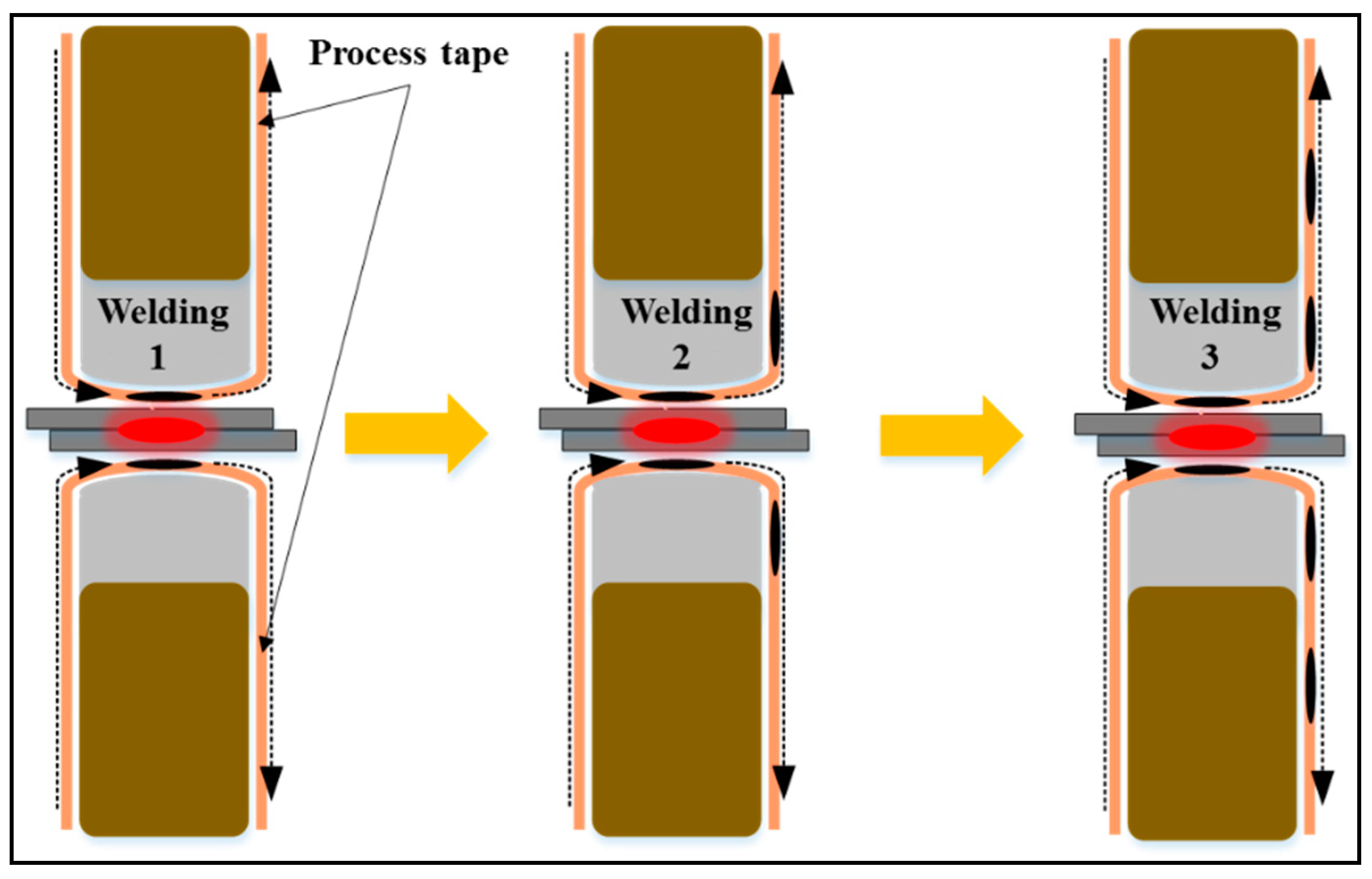
The DeltaSpot machine (Fronius, Wels, Austria) used in this study is mounted with a servogun to enable electrode force control. Furthermore, the DeltaSpot welding machine fundamentally differs from other spot welding machines in that a process tape runs between the base metal and the electrode. This process tape protects the electrode from contamination by the aluminum alloy, considerably extending the service life of the electrode. The process tape also increases weldability owing to its high electrical resistance, which compensates for the low resistivity of aluminum alloy and facilitates the resistance control of the weld zone. Figure 1 shows the schematic of a DeltaSpot welding process using process tapes. When the first welding is completed, the process tape between the electrode and the sheet advances. In the second welding, a new process tape is supplied and the welding proceeds. In the same way as the second welding, the third welding is supplied with a new process tape to proceed with the welding. This unique feature of DeltaSpot welding prevents electrode contamination and welding expulsion, and it increases the input heat by generating more resistance between the base metal and the electrode compared with other spot welding machines.
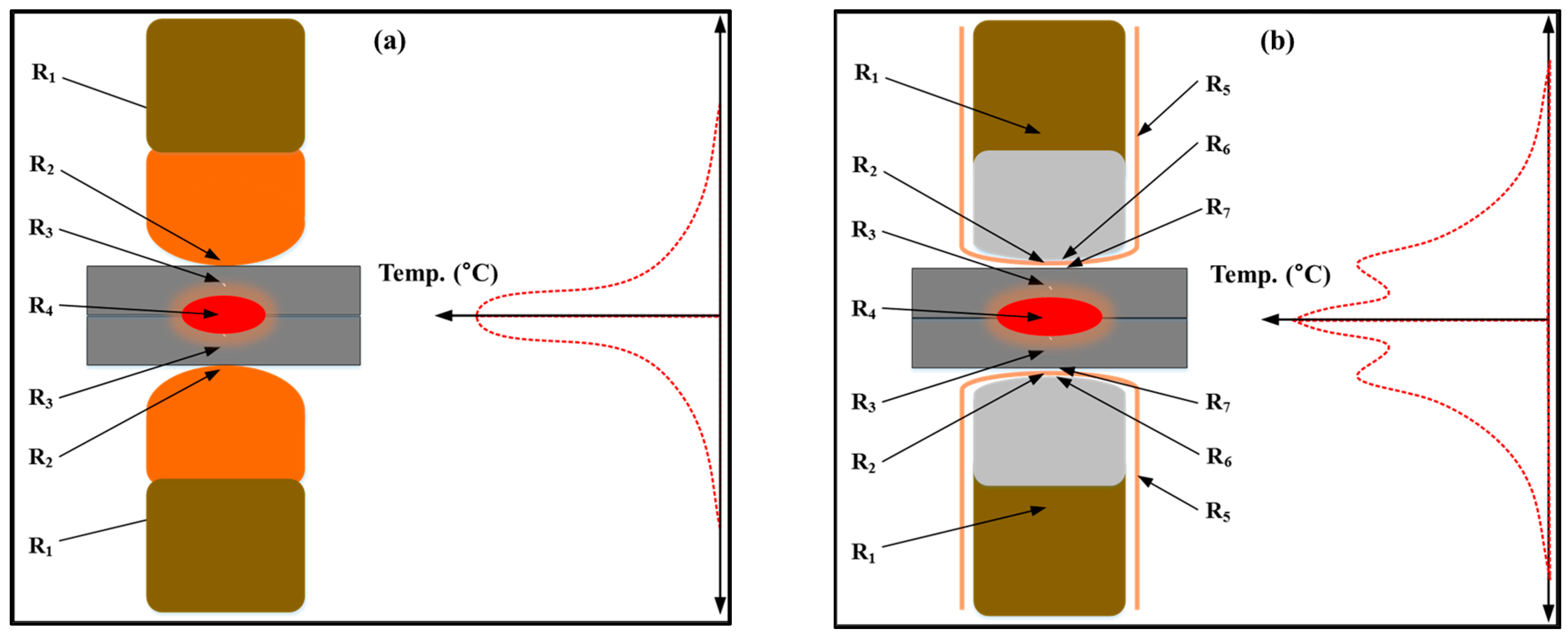
Figure 2 illustrates the resistance and temperature profiles in the spot welding area. Figure 2a shows the resistance and temperature profiles of a general spot welding area; Figure 2b shows those for a DeltaSpot welding area. As depicted in Figure 2b, significantly greater heat input can be obtained from the additional resistances occurring between the process tape and the electrode and between the process tape and the base metal.
2.2. Materials and Experimental Method
The materials used in this study were 6000 series aluminum alloy (Al 6K32) and 440 MPa grade steel (SGARC 440). Their chemical compositions are presented in Table 1.
To compensate for the difference in resistivity between steel (higher) and aluminum (lower), two types of process tape were used: PT1407 with a lower resistance between the steel specimen and the electrode and PT3000 with a higher resistance between the aluminum specimen and the electrode. Table 2 summarizes the basic properties of these two types of process tapes.
The tensile lap-shear test specimens were prepared in the shape illustrated in Figure 3, with a steel sheet fixed underneath an aluminum alloy sheet with an overlap length of 40 mm and the following sheet thicknesses: SGARC 440, 1.4 mm and 1.0 mm; Al 6K32, 1.6 mm and 1.0 mm. Three pairs of specimens for the tensile shear test, peel test, and cross-sectional examination were prepared. The experiment was repeated three times under the same welding conditions.
2.3. Weldability Evaluation Method
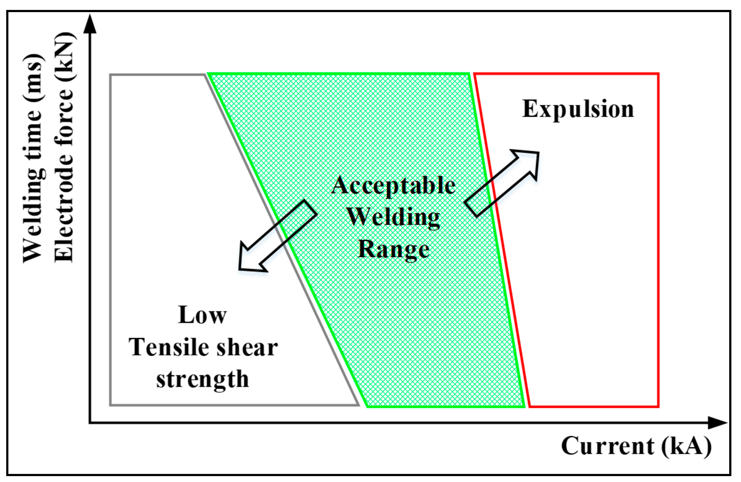
It is difficult to examine and measure an IMC layer, which is a significant factor in determining the weld quality of the dissimilar welding of aluminum alloy and steel, using non-destructive testing methods, such as X-ray testing, ultrasonic test, and computed tomography (CT). This is more difficult in RSW. Therefore, in this study, weldability was evaluated based on the magnitude of the tensile shear strength (TSS) measured by tensile shear testing. Furthermore, the nugget size of the weld zone was measured by examining its cross-section. For industrial applications, the lobe curve is used as the evaluation standard, as illustrated in Figure 5.
As shown in Figure 5, the lobe curve is determined based on the permissible TSS for the minimum acceptable weld zone, whereby the weld strength fails to meet the strength requirement if it is smaller than the permissible TSS or if the nugget diameter measured by the peel test is or smaller relative to the base metal thickness, t (mm). The maximum acceptable weld zone is determined by the occurrence of expulsion during welding by overheating. In general, the wider the acceptable weld zone, the better is the weldability. For the lobe curve used in this study, the horizontal axis represents the current and the vertical axis represents the current time and electrode force.
3. Results and Discussion
In our preliminary test, the up-slope time had significant effects on the weld strength and surface contamination of aluminum alloy sheets, and had a suitable condition to guarantee high tensile shear strength and improved surface quality of the weld below 150 ms. The down-slope time below the condition of 450 ms turned out to be a significant parameter for reducing weld defects of aluminum alloy sheets. It was also found that the pre-force time and hold time have significant effects on the weld surface quality and weld defects in certain test ranges: From −50 to 50 ms for the pre-force time and from 0 to 150 ms for the hold time. However, since force 2 did not have significant effects on both weld strength and weld defects below 5 kN, force 2 was fixed to 5 kN. Since the welding current, force 1, and main current time were found to be the most significant parameters among the eight parameters, and are usually adjusted in automotive assembly lines to improve welding quality, these parameters were selected and used for deriving suitable welding ranges. In addition, the welding schedules and specifications of actual automotive assembly lines were considered in order to select and set the test range of all eight process parameters.
3.1. Effect of DeltaSpot Welding in Improving Weldability
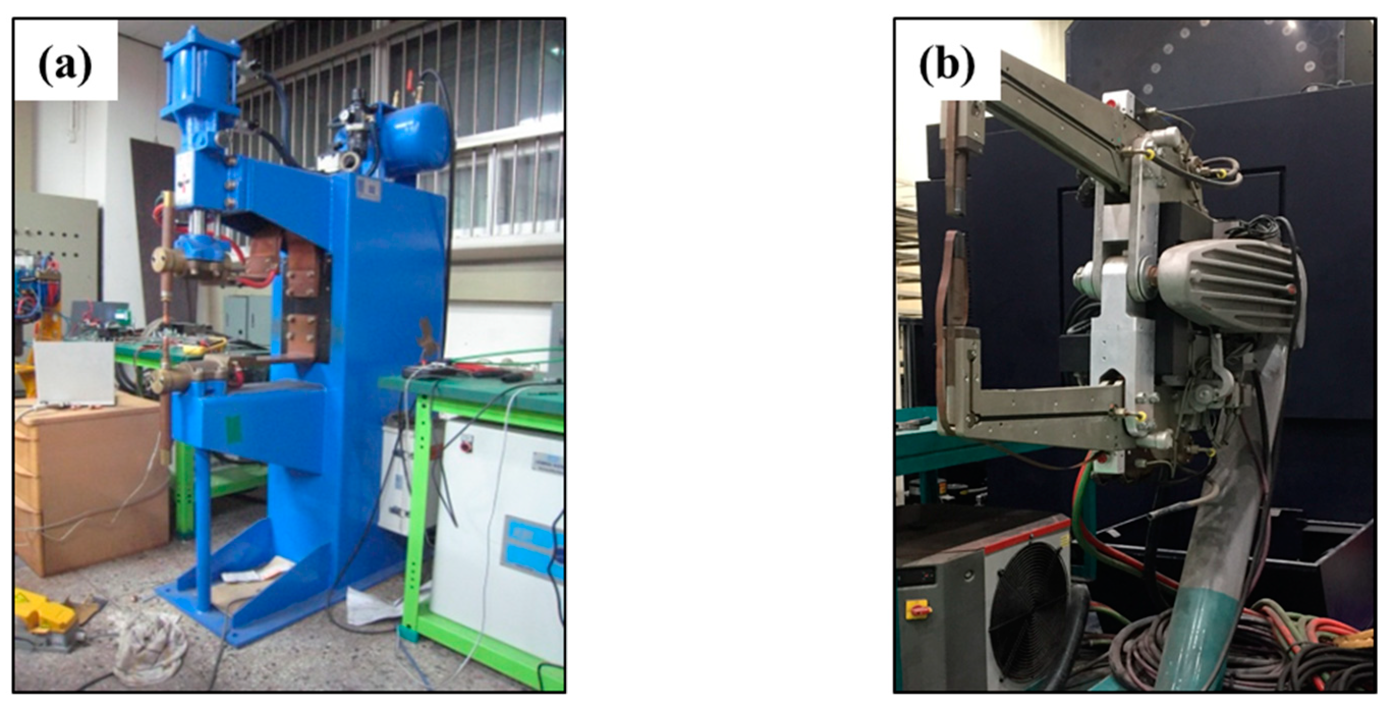
In this study, a weldability comparison was performed between inverter direct current (DC) spot welding and DeltaSpot welding. The materials used in this experiment are presented in Table 1; the sheet thickness was 1.4 mm for SGARC 440 and 1.6 mm for Al6K32. The basic properties of the DeltaSpot welding process tapes are presented in Table 2. Figure 6 shows the welding machines used for the comparison experiment: (a) and (b) are the inverter DC spot welding machine (Harm-Wende, Hamburg, Germany) and DeltaSpot welding machine (Fronius, Wels, Austria), respectively.
The comparison experiment was performed under the welding conditions summarized in Table 3, which shows that the electrode force was fixed at 2 kN and the main current time and current were varied.
Table 4 presents images of the fracture modes and cross-sections of the inverter DC spot weld zones of the test specimens welded under the conditions described in Table 3. Table 5 summarizes the fracture modes, expulsion, nugget diameter, and TSS.
In Table 4, when the main current time was 166 ms, interfacial fracture occurred at all current conditions and expulsion occurred at the current condition of 13 kA. At 332 ms, the plug fracture occurred at all current conditions, and the expulsion occurred at current conditions of 11 kA and 13 kA. At 500 ms, interfacial fracture occurred at all current conditions, and expulsion occurred at current conditions of 11 kA and 13 kA.
Table 6 shows images of the fracture modes and cross-sections of the DeltaSpot weld zones of the test specimens welded under the same welding conditions, and Table 7 presents the fracture modes, expulsion, nugget diameter, and TSS.
In Table 6, when the main current time was 166 ms, interfacial fracture occurred at all current conditions, but no expulsion occurred. At 332 ms, plug fracture occurred at all current conditions and expulsion occurred at the current condition of 13 kA. At 500 ms, interfacial fracture occurred at the current condition of 9 kA, and expulsion occurred under all current conditions.
The experimental results in Table 5 and Table 7 show that the DeltaSpot specimen was welded at a lower current and had a wider plug fracture case than that of the inverter DC specimen. Since DeltaSpot can obtain sufficient weld quality at a lower current range, the DeltaSpot equipment can apply a welding transformer with a smaller capacity compared to that of conventional inverter DC welding equipment, which leads to a cost reduction of the welding equipment and system. In addition, the nugget diameter of the welding condition under which the plug fracture occurred is larger than that for DC spot welding. Further, it can be confirmed that DeltaSpot welding achieves better weld strength than inverter DC spot welding even at a relatively low welding current. Thus, the comparative experiments confirm that DeltaSpot welding can be performed with a relatively larger suitable welding range and better weld quality. That is, DeltaSpot welding achieves a wider suitable welding range, which is attributed to the effect of compensating for the resistivity difference when welding dissimilar metals using a process tape with lower resistance for the steel electrode and that with a higher resistance for the aluminum alloy electrode.
3.2. Effects of DeltaSpot Welding Parameters
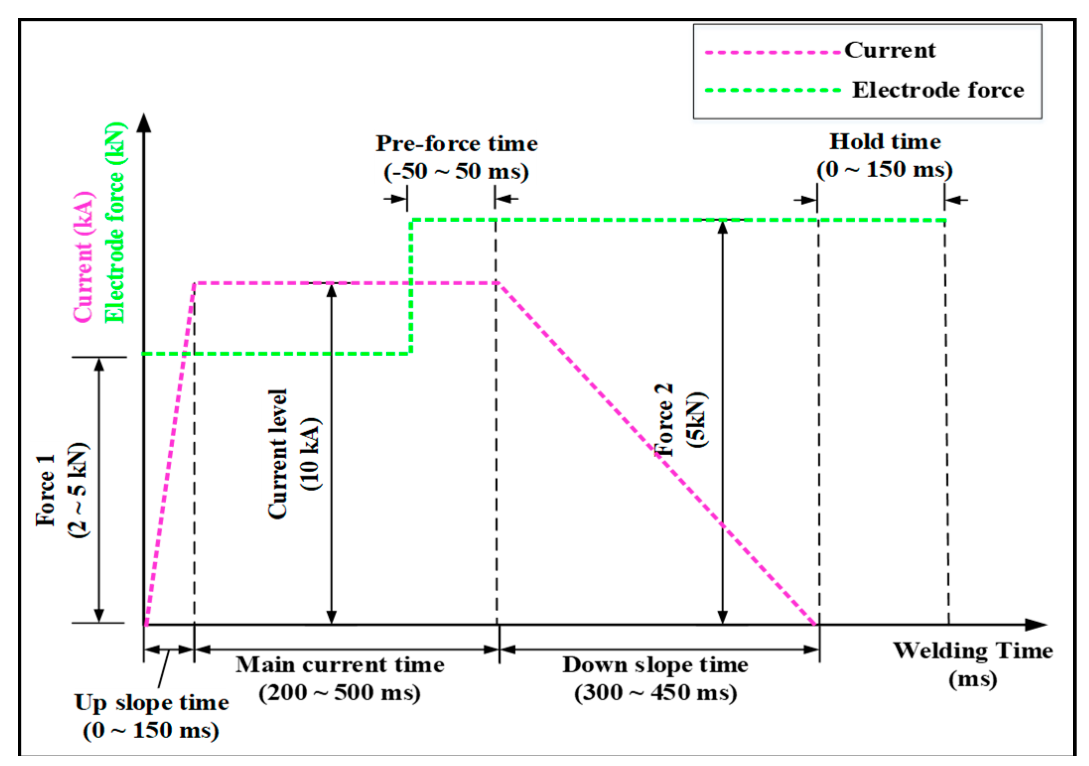
In this study, eight welding parameters, which are defined in Figure 7, were selected based on previous studies [35,36]. The up-slope time, main current time, down-slope time, and current level are related to the profile of the welding current. The profile of the electrode force was determined by setting the force 1, force 2, hold time, and pre-force time. In particular, the pre-force time is defined as the positive value when the magnitude of the electrode force changes from force 1 to force 2 during the main current time. Conversely, the pre-force time has a negative value when the magnitude of the electrode force changes from force 1 to force 2 after the main current time. To investigate the effects of the welding parameters, the basic welding conditions were set as indicated in Table 8, which presents the reference conditions for the experiment established based on the results of [35] regarding the DeltaSpot welding of aluminum alloy specimens with the same thickness. Force 2 was applied at the end of the welding process to reduce the resistivity loss through the high electrode force and to prevent welding defects during the current passage time, whereby force 2 should be at least 5 kN to have the effect of removing weld zone defects [35]. Therefore, force 2 was set at 5 kN.
The characteristics of the process parameters associated with dissimilar metal welding were evaluated by welding aluminum alloy and carbon steel sheets of the same thickness (1.0 mm) using the DeltaSpot welding machine. In this study, based on the results of pre-tested aluminum alloy DeltaSpot welding, experiments were conducted under the welding conditions summarized in Table 9 to evaluate the characteristics of the process variables [35,36].
The experimental results for each process parameter are presented in Table 10. The weldability was evaluated in terms of expulsion, TSS, and fracture mode.
The effects of the individual process parameters on the weldability of aluminum alloy with carbon steel via DeltaSpot welding were analyzed. The welding conditions were derived based on the analysis results; the up-slope time should be reduced to the minimum possible level because the weld strength decreases as the up-slope time increases. The experimental results reveal that a high weld strength and satisfactory button size were achieved at 50 ms. Given that the weld strength is determined in the initial welding phase, the main current time does not need to be long. The experimental results demonstrate that expulsion occurs when the main current time exceeds 400 ms. Accordingly, the optimum condition was set to 300 ms. The down-slope time should be maintained for at least 300 ms to ensure welding defect removal. At 450 ms, no button fracture and expulsion occurred; however, the reference weld strength was not achieved. Accordingly, the optimum condition was set to 300 ms. The optimum force 1 was set to 2 kN, because the highest weld strength and satisfactory button size were obtained at 2 kN. The application of the pre-force time was found to lower the weld strength. The hold time, which is the time to maintain the electrode force after the current has passed to prevent cracking during the cooling-induced contraction of the weld metal, was found to satisfy the weld strength and button size at 100 ms. Table 11 outlines the optimum conditions of the individual process parameters for DeltaSpot welding of dissimilar metals as derived from the analysis of the experimental results.
3.3. Weldability Evaluation with Respect to the Main Current Time and Force 1
The main current time plays an important role in the RSW of aluminum alloy to steel. Its effect on weldability was analyzed, given its importance as a parameter, allowing sufficient time for the molten aluminum alloy to ensure good wetting of the surface of the heated carbon steel. The related experimental conditions are outlined in Table 12. All process parameters except for main current time, force 1, and current were set to the values listed in Table 11.
Table 13, Table 14 and Table 15 are lobe curves as functions of the main current time. The values within the green outline are those satisfying the standards for the permissible TSS (= no expulsion) and button size. No TSS values are provided for the areas affected by expulsion.
At a main current time of 300 ms (Table 13), the interfacial fracture was the main welding defect due to insufficient heat input in the low-current range. This characteristic made the weldability sensitive to the electrode force in the welding current range of 8 to 9 kA; however, a very stable weld zone was achieved at welding currents greater than 10 kA. An acceptable weld zone was achieved at currents exceeding 14 kA as well. In contrast, as the main current time increased, an acceptable weld zone was achieved in the low-current range, but expulsion occurred in the high-current range of 13 to14 kA due to excessive input heat. In addition, an overall tendency of the acceptable weld zone to move from the high- to low-current range was observed, whereby no acceptable weld zone was formed at currents less than 7 kA despite this change. These results indicate that the RSW of aluminum alloy to carbon steel is possible at a current ≥7 kA. Furthermore, increasing the main current time did not result in any significant increase in weld strength.
3.4. Evaluation of Coating-Dependent Dissimilar Metal Welding Characteristics
In the RSW of aluminum alloy to carbon steel, the aluminum alloy melts and the carbon steel is heated at the aluminum alloy melting point or lower. The molten aluminum alloy provides wetting of the surface of heated carbon steel to form a new alloy layer, namely, an IMC layer, which acts as a bonding layer equivalent to a nugget in same-metal welding.
For comparison, the weld zone characteristics of dissimilar metal welding with zinc-coated and uncoated steel sheets, which are widely used in industrial settings, were evaluated. Weldability was evaluated under the experimental conditions outlined in Table 12. The lobe curve in Table 16 shows the resulting weldability characteristics.
Table 16 shows that the weld strength was very low and no button fracture appeared in the RSW of aluminum alloy to uncoated steel, demonstrating the existence of weldability problems without any regularity that would allow the identification of the effects of welding conditions on weldability. From this finding, it may be assumed that the zinc in the zinc-coating layer plays an important role in dissimilar metal welding of aluminum alloy onto carbon steel. This role may be explained by the fact that zinc, which has a melting point similar to that of aluminum alloy, melts during the welding process and forms an IMC layer, thus improving the bonding force; this effect cannot occur when aluminum alloy is welded onto uncoated steel without a zinc layer.
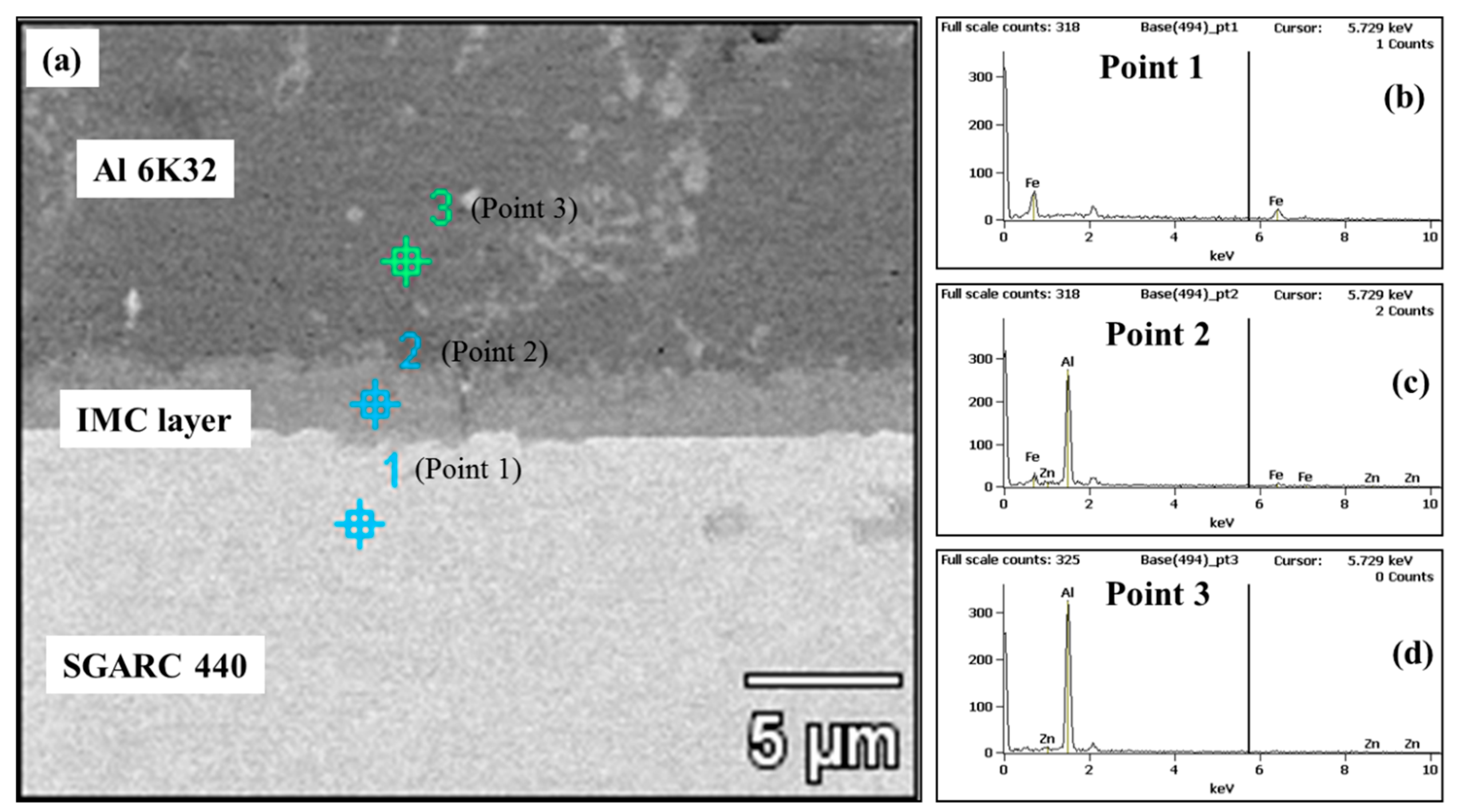
Figure 8a illustrates the results of the SEM-EDS analysis performed at different points in dissimilar metal RSW of zinc-coated steel: Figure 8b at point 1 inside the zinc-coated steel sheet (SGARC 440); Figure 8c at point 2 inside the IMC layer; and Figure 8d at point 3 inside the aluminum alloy sheet (Al 6K32). The results of component analysis at each point are summarized in Table 17.
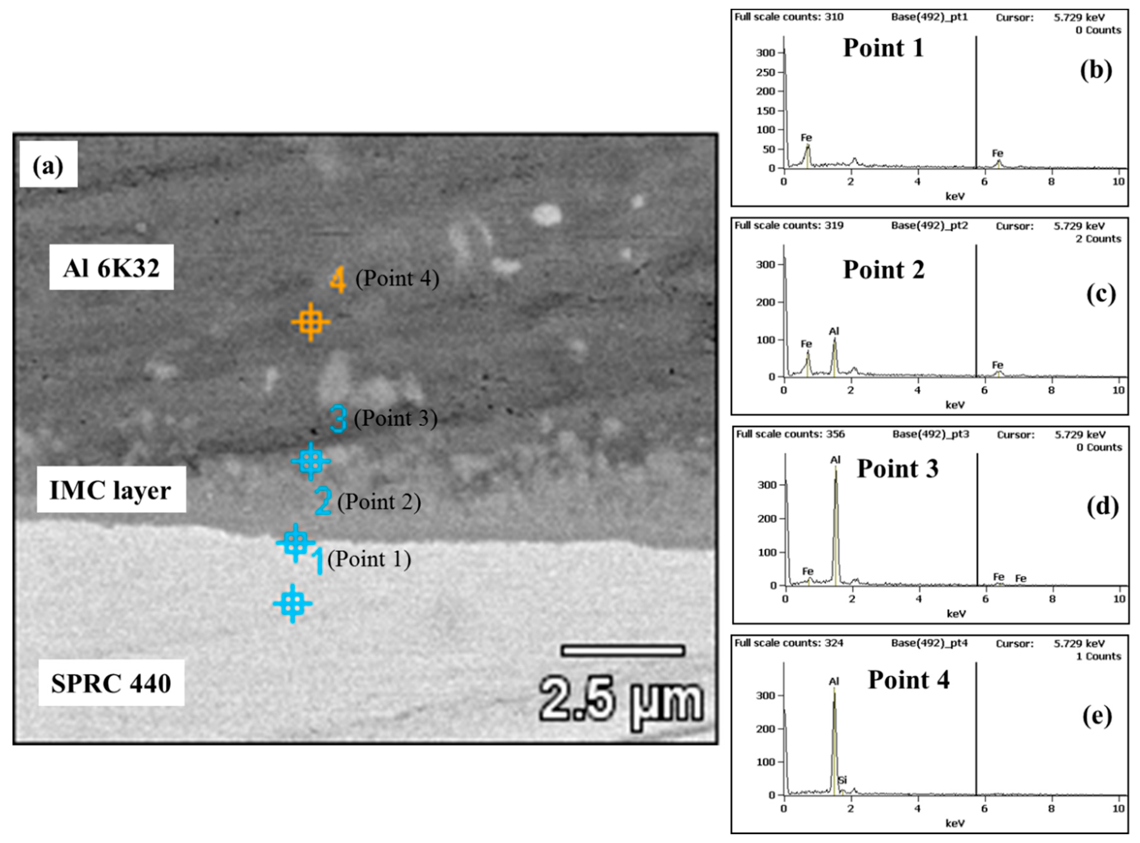
Figure 9a outlines the components of the aluminum alloy sheet, IMC layer, and uncoated carbon steel sheet as analyzed by SEM-EDS at three points in the two base metal sheets and the IMC layer: Figure 9b at point 1 inside the uncoated steel sheet (SPRC 440); Figure 9c at point 2 inside the IMC layer close to the uncoated steel sheet; Figure 9d at point 3 inside the IMC layer close to the aluminum alloy sheet; and Figure 9e at point 4 inside the aluminum alloy sheet (Al 6K32). The results of component analysis at each point are summarized in Table 18.
The zinc-coated steel was analyzed to have the following components. The IMC layer zone (point 2) contained a compound with a mixing ratio of Al(69.04%):Fe(30.30%):Zn(0.65%). In the case of uncoated steel, a compound was extracted from the IMC layer closer to the aluminum alloy sheet (point 3), which was analyzed to have a mixing ratio closer to that of aluminum alloy, Al(74.36%):Fe(25.64%), and the compound extracted from the IMC layer closer to the uncoated steel sheet (point 2) was analyzed to have a mixing ratio of Al(20.44%):Fe(79.56%). These SEM-EDS analysis results suggest that the difference in the bonding force between coated and uncoated steel sheets is attributable to the presence of zinc in the IMC layer.
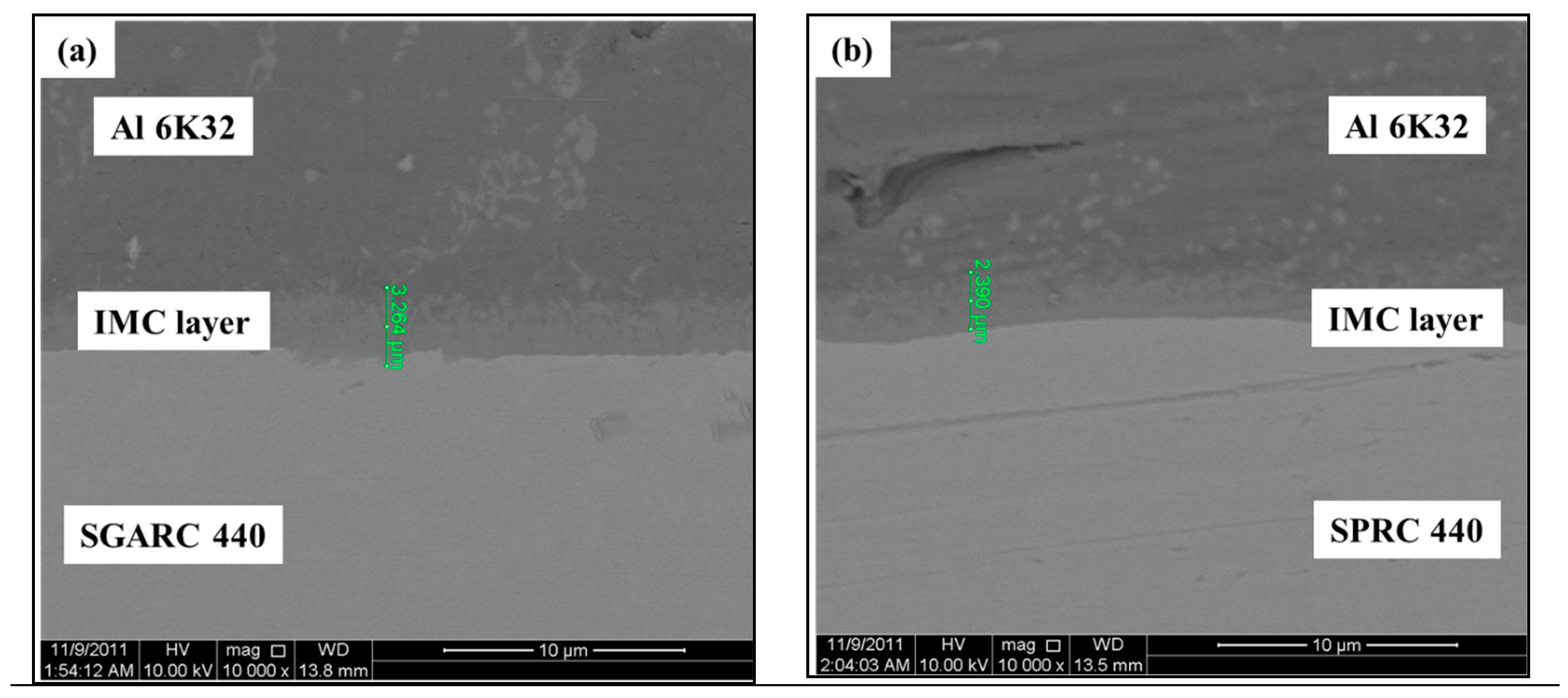
Figure 10 shows the difference in the thickness of the IMC layer between the zinc-coated steel (Figure 10a, SGARC 440) and uncoated steel (Figure 10b, SPRC 440) sheets: 3.264 μm vs. 2.390 μm. In general, a thinner IMC layer, which is highly brittle, has a higher strength. In the case of uncoated steel, however, a simple thickness comparison is not a good basis for the comparative evaluation of weld strength because of the different chemical compositions of the compounds extracted from the IMC layer [37].
4. Conclusions
In this study, RSW between aluminum alloy (Al 6K32 1.0t) and carbon steel (SGARC 440 1.0t), which could not be solved using conventional RSW processes, was achieved by using a DeltaSpot welding system, and the RSW characteristics for different base metal combinations of aluminum alloy and various steel types were analyzed. The findings of this study can be summarized as follows:
- (1)
- In the RSW of aluminum alloy to steel, lobe curve comparison verified the superiority of DeltaSpot welding to inverter DC spot welding in terms of the acceptable weld zone and weld stability owing to the effects of the process tape.
- (2)
- The optimum values of six DeltaSpot welding process parameters were derived from the analysis results for the welding characteristics of eight process parameters selected based on the results of an earlier study on the RSW of an aluminum alloy (Al 6K32) of the same thickness.
- (3)
- Weldability was evaluated as a function of the main current time, a main parameter along with the current level and force 1. The results of the lobe curve analysis revealed an overall tendency of the acceptable weld zone to move from the high- to low-current range, whereby no acceptable weld zone was formed in the range lower than 7 kA.
- (4)
- Weldability of aluminum alloy to different steel types was evaluated in order to enhance its applicability to different welding process conditions based on the steel types used in vehicle body assembly. The comparison of the weldability of aluminum alloy to zinc-coated and uncoated steel sheets revealed its weldability to uncoated steel sheets to be very low. This low weldability seems to be attributable to the fact that zinc melted onto the surface of the zinc-coated steel sheet forms a compound in the IMC layer, thus improving the bonding force. The difference in the zinc content in the IMC layer was verified by SEM-EDS analysis.
The significance of this study lies in the fact that a method of improving the weldability in the dissimilar metal weld zone was developed for applications to aluminum alloy for industrial use as a lightweight material. Furthermore, the developed methodology can be used to analyze the weldability of various combinations of weld materials with the aim of establishing a database to strengthen DeltaSpot’s applicability in the automotive industry.
Author Contributions
S.S. analyzed the data and wrote the paper; D.-J.P. performed the welding experiments; J.Y. analyzed the data and reviewed the paper; S.R. reviewed the paper.
Funding
This research was supported by the Ministry of Trade, Industry and Energy (MI, Korea).
Acknowledgments
This work was supported by the Industrial Technology Innovation Program (No. 10063421, ‘Development of the in-line welds quality estimation system and network-based quality control technology in arc and spot welds of ultrahigh-strength steels for automotive parts assembly’) funded By the Ministry of Trade, Industry and Energy (MI, Korea).
Conflicts of Interest
The authors declare no conflict of interest.
References
- Ramazani, A.; Mukherjee, K.; Abdurakhmanov, A.; Abbasi, M.; Prahl, U. Characterization of microstructure and Mechanical Properties of Resistance spot welded DP600 steel. Metals 2015, 5, 1704–1716. [Google Scholar] [CrossRef]
- Huin, T.; Dancette, S.; Fabrègue, D.; Dupuy, T. Investigation of the failure of advanced high strength steels heterogeneous spot welds. Metals 2016, 6, 111. [Google Scholar] [CrossRef]
- Yu, J. Adaptive Resistance Spot Welding Process that Reduces the Shunting Effect for Automotive High-Strength Steels. Metals 2018, 8, 775. [Google Scholar] [CrossRef]
- Džupon, M.; Kaščák, Ľ.; Spišák, E.; Kubík, R.; Majerníková, J. Wear of Shaped Surfaces of PVD Coated Dies for Clinching. Metals 2017, 7, 515. [Google Scholar] [CrossRef]
- Kazdal Zeytin, H.; Ertek Emre, H.; Kaçar, R. Properties of resistance spot-welded TWIP steels. Metals 2017, 7, 14. [Google Scholar] [CrossRef]
- He, X.; Deng, C.; Zhang, X. Fretting behavior of SPR joining dissimilar sheets of titanium and copper alloys. Metals 2016, 6, 312. [Google Scholar] [CrossRef]
- Fridlyander, I.N.; Sister, V.G.; Grushko, O.E.; Berstenev, V.V.; Sheveleva, L.M.; Ivanova, L.A. Aluminum alloys: promising materials in the automotive industry. Met. Sci. Heat Treat. 2002, 44, 365–370. [Google Scholar] [CrossRef]
- Kim, Y.; Park, K.Y.; Lee, K.D. Development of Welding Technologies for Lightweight Vehicle. J. Weld. Join. 2011, 29, 1–3. [Google Scholar] [CrossRef]
- Chang, W.S.; Choi, K.Y.; Kim, S.H.; Kweon, Y.G. Some Aspects of Friction Stir Welding and Its Application Technologies. J. Weld. Join. 2001, 19, 7–15. [Google Scholar]
- Yeon, Y.M.; Lee, W.B.; Jung, S.B. Microstructures and Characteristics of Friction-Stir-Welded Joints in Aluminum Alloys. J. Weld. Join. 2001, 19, 584–590. [Google Scholar]
- Kim, H.T.; Kil, S.C. High Efficient Welding Technology of the Car Bodies. J. Weld. Join. 2016, 34, 62–66. [Google Scholar] [CrossRef]
- Inaba, T.; Tokuda, K.; Yamashita, H.; Takebayashi, Y.; Minoura, T.; Sasabe, S. Wrought aluminum technologies for automobiles. Kobelco Technol. Rev. 2005, 26, 55–62. [Google Scholar]
- Barnes, T.A.; Pashby, I.R. Joining techniques for aluminium spaceframes used in automobiles: Part II—Adhesive bonding and mechanical fasteners. J. Mater. Process. Technol. 2000, 99, 72–79. [Google Scholar] [CrossRef]
- Yum, D.B.; Ko, J.B.; Choi, B.K.; Lee, S.G.; Kim, A.K. Evaluation of Resistance Spot Welding Weldability of Aluminum Alloy 5000 Series. Trans. Kor. Soc. Mach. Tool Eng. 2002, 11, 8–13. [Google Scholar]
- Cai, W.; Wang, P.C.; Yang, W. Assembly dimensional prediction for self-piercing riveted aluminum panels. Int. J. Mach. Tools Manuf. 2005, 45, 695–704. [Google Scholar] [CrossRef]
- Kim, J.Y.; Lee, C.J.; Lee, S.K.; Ko, D.C.; Kim, B.M. Effect of shape parameters of tool on improvement of joining strength in clinching. Trans. Mater. Process. 2009, 18, 392–400. [Google Scholar]
- Rao, H.M.; Kang, J.; Huff, G.; Avery, K. Structural Stress Method to Evaluate Fatigue Properties of Similar and Dissimilar Self-Piercing Riveted Joints. Metals 2019, 9, 359. [Google Scholar] [CrossRef]
- Peng, G.; Yan, Q.; Hu, J.; Chen, P.; Chen, Z.; Zhang, T. Effect of Forced Air Cooling on the Microstructures, Tensile Strength, and Hardness Distribution of Dissimilar Friction Stir Welded AA5A06-AA6061 Joints. Metals 2019, 9, 304. [Google Scholar] [CrossRef]
- Patel, V.; Li, W.; Wang, G.; Wang, F.; Vairis, A.; Niu, P. Friction Stir Welding of Dissimilar Aluminum Alloy Combinations: State-of-the-Art. Metals 2019, 9, 270. [Google Scholar] [CrossRef]
- Nakamura, T.; Obikawa, T.; Nishizaki, I.; Enomoto, M.; Fang, Z. Friction Stir Welding of Non-Heat-Treatable High-Strength Alloy 5083-O. Metals 2018, 8, 208. [Google Scholar] [CrossRef]
- Li, Z.; Hao, C.; Zhang, J.; Zhang, H. Effects of sheet surface conditions on electrode life in resistance welding aluminum. Weld. J. 2007, 86, 81s–89s. [Google Scholar]
- Park, S.H.; Park, B.C.; Kim, Y.G.; Beak, U.R. Fusion Zone Characteristics of Dissimilar Aluminum Alloys joining. In Proceedings of the KWS Conference, The Korean Welding and Joining Society, Jeonju, Korea, 15–16 November 2007; pp. 141–143. [Google Scholar]
- Cho, S.M. Resistance welding and resistance joining technology to Fe-base material of Al-alloy. J. Weld. Join. 2001, 19, 14–22. [Google Scholar]
- Rashid, M.; Fukumoto, S.; Medley, J.B.; Villafuerte, J.; Zhou, Y. Influence of lubricants on electrode life in resistance spot welding of aluminum alloys. Weld. J. 2007, 86, 62s–70s. [Google Scholar]
- Yeon, Y.M.; Lee, W.B.; Lee, C.Y.; Jung, S.B.; Song, K. Joint Characteristics of Spot Friction Stir Welded A 5052 Alloy Sheet. J. Weld. Join. 2006, 24, 71–76. [Google Scholar]
- Yeon, Y.M.; Lee, C.Y.; Lee, W.B.; Jung, S.B.; Chang, W.S. Spot friction stir welding and characteristics of joints in aluminum alloys. J. Weld. Join. 2005, 23, 16–20. [Google Scholar]
- Thornton, P.H.; Krause, A.R.; Davies, R.G. Aluminum spot weld. Weld. J. Res. Suppl. 1996, 75, 101s–108s. [Google Scholar]
- Sun, X.; Dong, P. Analysis of aluminum resistance spot welding processes using coupled finite element procedures. Weld. J. 2000, 79, 215s–221s. [Google Scholar]
- Senkara, J.; Zhang, H. Cracking in spot welding aluminum alloy AA5754. Weld. J. 2000, 79, 194s–201s. [Google Scholar]
- Browne, D.J.; Chandler, H.W.; Evans, J.T.; Wen, J. Computer simulation of resistance spot welding in aluminum: Part I. Weld. J. Res. Suppl. 1995, 74, 339s–344s. [Google Scholar]
- Browne, D.J.; Chandler, H.W.; Evans, J.T.; James, P.S.; Wen, J.; Newton, C.J. Computer simulation of resistance spot welding in aluminum: Part II. Weld. J. Res. Suppl. 1995, 74, 417s–422s. [Google Scholar]
- Qiu, R.; Iwamoto, C.; Satonaka, S. The influence of reaction layer on the strength of aluminum/steel joint welded by resistance spot welding. Mater. Charact. 2009, 60, 156–159. [Google Scholar] [CrossRef]
- Qiu, R.; Iwamoto, C.; Satonaka, S. Interfacial microstructure and strength of steel/aluminum alloy joints welded by resistance spot welding with cover plate. J. Mater. Process. Technol. 2009, 209, 4186–5193. [Google Scholar] [CrossRef]
- Mortazavi, S.N.; Marashi, P.; Pouranvari, M.; Masoumi, M. Investigation on joint strength of dissimilar resistance spot welds of aluminum alloy and low carbon steel. Adv. Mater. Res. 2011, 264–265, 384–389. [Google Scholar] [CrossRef]
- Yu, J.; Choi, Y.; Shim, J.; Cho, Y.; Rhee, S. A study on resistance spot welding for aluminum alloys with spooling process tapes. In Proceedings of the International Conference on Advances in Welding Science and Technology for Construction, Energy and Transportation, AWST, held in Conjunction with the 63rd Annual Assembly of the International Institute of Welding, IIW 2010, Istanbul, Turkey,, 15–16 July 2010; pp. 679–684. [Google Scholar]
- Yeom, J. A Study on Resistance Spot Welding of Aluminum Alloys Based on the Current and Electrode Force Characteristics Analysis. Master’s Thesis, Hanyang University, Seoul, Korea, 2007. [Google Scholar]
- Ikeuchi, K.; Yamamoto, N.; Takahashi, M.; Aritoshi, M. Effect of interfacial reaction layer on bond strength of friction-bonded joint of Al alloys to steel. Trans. JWRI 2005, 34, 1–10. [Google Scholar]
Figure 1.
DeltaSpot welding process with process tape.

Figure 2.
Spot welding resistance and temperature distribution: (a) General spot welding; (b) spot welding with process tape.
Figure 2.
Spot welding resistance and temperature distribution: (a) General spot welding; (b) spot welding with process tape.

Figure 3.
Spot welding specimen size and method.
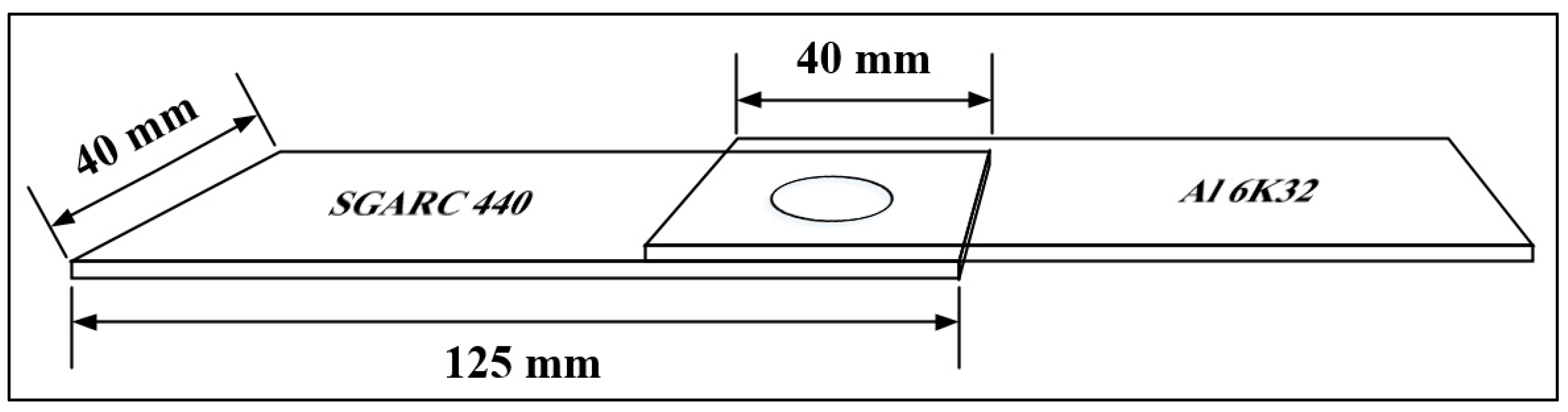
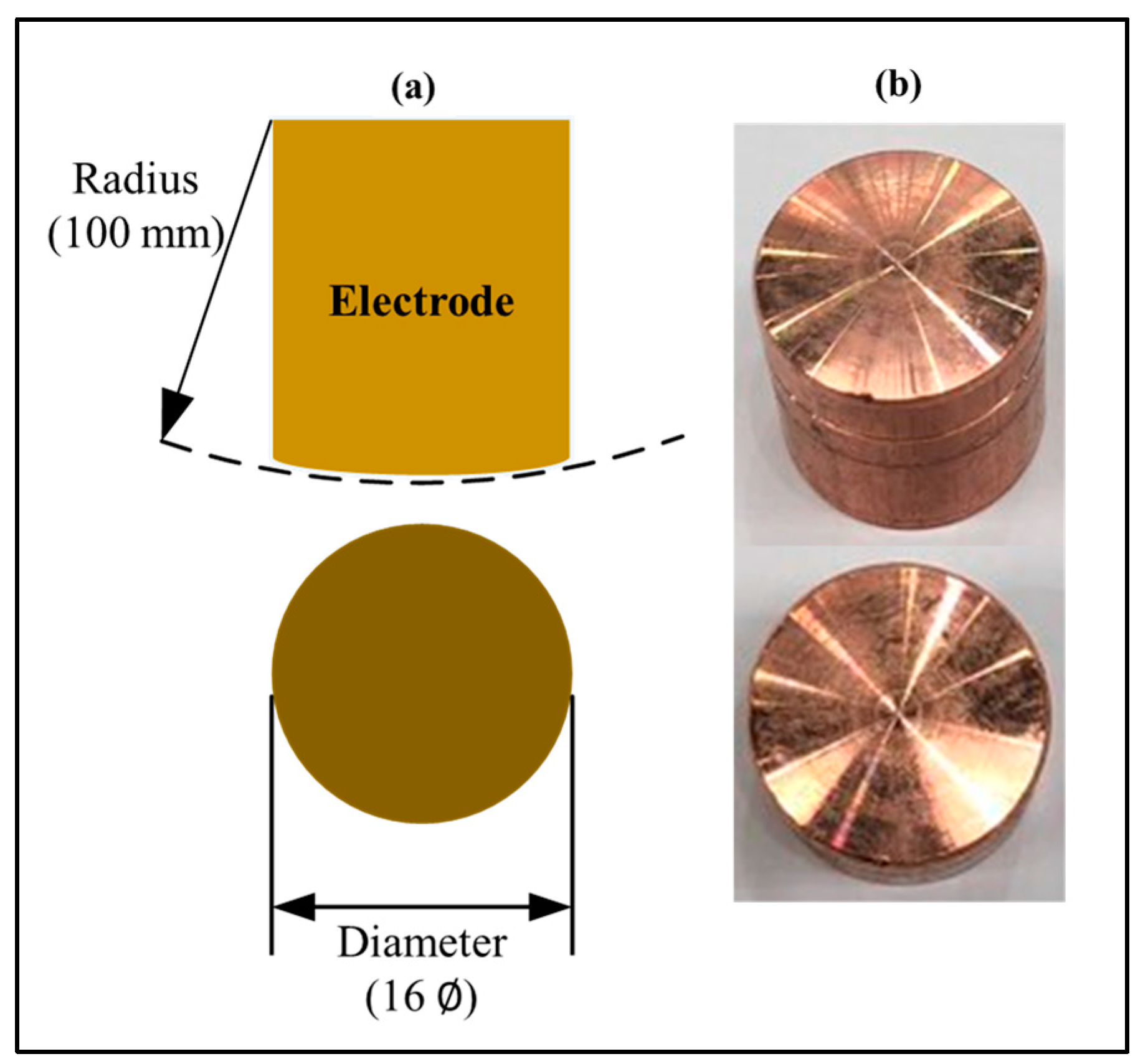
Figure 4.
Electrode used in DeltaSpot: (a) electrode size; (b) electrode shape.

Figure 5.
Schematic diagram illustrating the acceptable welding range (weld lobe). The vertical axis represents welding time or electrode force; the horizontal axis represents welding current.
Figure 5.
Schematic diagram illustrating the acceptable welding range (weld lobe). The vertical axis represents welding time or electrode force; the horizontal axis represents welding current.

Figure 6.
Experimental equipment: (a) Inverter direct current (DC) spot welding machine; (b) DeltaSpot welding machine.
Figure 6.
Experimental equipment: (a) Inverter direct current (DC) spot welding machine; (b) DeltaSpot welding machine.

Figure 7.
Schematic diagram illustrating the process parameters of DeltaSpot welding with test values.
Figure 7.
Schematic diagram illustrating the process parameters of DeltaSpot welding with test values.

Figure 8.
Energy dispersive X-ray spectroscopy (EDS) analysis locations in the welded section: (a) SEM image of dissimilar spot welds of aluminum alloy/zinc-coating steel.; (b) zinc-coating steel base metal point 1; (c) intermetallic compound (IMC) layer point 2; (d) aluminum alloy base metal point 3.

Figure 9.
Energy dispersive X-ray spectroscopy (EDS) analysis locations in the welded section: (a) SEM image of dissimilar spot welds of aluminum alloy/non-coating steel. (b) Non-coating steel base metal point 1; (c) close to non-coating steel intermetallic compound (IMC) layer point 2; (d) close to aluminum alloy IMC layer point 3; (d) aluminum alloy base metal point 4.

Figure 10.
Intermetallic compound (IMC) layer thickness measurement: (a) Zinc-coating steel; (b) non-coating steel.
Figure 10.
Intermetallic compound (IMC) layer thickness measurement: (a) Zinc-coating steel; (b) non-coating steel.

Table 1.
Material compositions of Al 6K32 and SGARC 440 (wt %).
| Al 6K32 | Mg | Si | Fe | Cu | Mn | Cr | Zn | Ti |
| 0.02 | 1.0 | 0.13 | 0.01 | 0.07 | 0.01 | 0.01 | 0.01 | |
| SGARC 440 | Si | Cu | Mn | Cr | Ni | Mo | V | C |
| 0.14 | 0.1 | 1.4 | 0.1 | 0.1 | 0.05 | 0.01 | 0.09 |
Table 2.
Process tape types.
| Base Metal | Process Tape | Tape Material | Heat Input from Outside |
|---|---|---|---|
| Al 6K32 | PT 3000 | CrNi | High |
| SGARC 440 | PT 1407 | Steel | Medium |
Table 3.
Welding conditions.
| Welding Conditions | Profiles of Welding Current and Electrode Force | |
|---|---|---|
| Current (kA) | 9, 11, 13 | 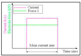 |
| Up slope time (ms) | 0 | |
| Main current time (ms) | 166, 332, 500 | |
| Down slope time (ms) | 0 | |
| Force 1 (kN) | 2 | |
| Force 2 (kN) | 0 | |
| Pre-force time (ms) | 0 | |
| Hold time (ms) | 0 | |
Table 4.
DC spot weld fracture shape and cross-sectional image.
| Main Current Time (ms) | Item | Current Level (kA) | ||
|---|---|---|---|---|
| 9 | 11 | 13 | ||
| 166 | Fracture mode |  |  | 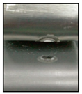 |
| Cross Section | 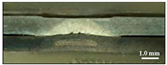 | 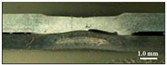 | 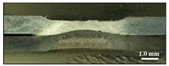 | |
| 332 | Fracture mode |  | 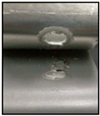 | 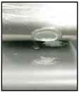 |
| Cross Section | 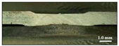 | 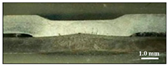 | 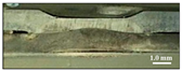 | |
| 500 | Fracture mode | 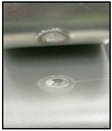 | 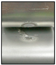 | 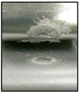 |
| Cross Section | 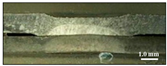 | 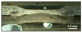 |  | |
Table 5.
Weldability analysis of DC spot welding according to conditions.
| Main Current Time (ms) | Item | Current Level (kA) | ||
|---|---|---|---|---|
| 9 | 11 | 13 | ||
| 166 | Fracture mode | Interfacial | Interfacial | Interfacial |
| Expulsion | - | - | expulsion | |
| Nugget diameter (mm) | - | - | - | |
| TSS (kN) | 1.2 | 2.7 | 2.4 | |
| 332 | Fracture mode | Plug | Plug | Plug |
| Expulsion | - | expulsion | expulsion | |
| Nugget diameter (mm) | 3.8 | 4.6 | 6.5 | |
| TSS (kN) | 2.1 | 2.9 | 3.8 | |
| 500 | Fracture mode | Interfacial | Interfacial | Interfacial |
| Expulsion | - | expulsion | expulsion | |
| Nugget diameter (mm) | - | - | - | |
| TSS (kN) | 2.8 | 3.4 | 3.4 | |
Table 6.
DeltaSpot weld fracture shape and cross-sectional image.
| Main Current Time (ms) | Item | Current Level (kA) | ||
|---|---|---|---|---|
| 9 | 11 | 13 | ||
| 166 | Fracture shape | 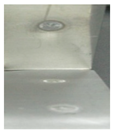 |  | 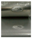 |
| Cross Section | 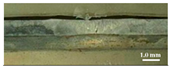 |  | 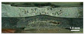 | |
| 332 | Fracture shape | 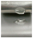 |  | 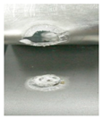 |
| Cross Section | 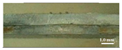 | 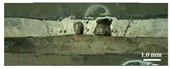 | 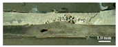 | |
| 500 | Fracture shape |  | 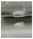 | 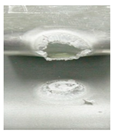 |
| Cross Section |  | 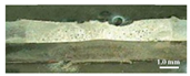 | 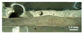 | |
Table 7.
Weldability analysis of DeltaSpot welding according to conditions.
| Main Current Time (ms) | Item | Current Level (kA) | ||
|---|---|---|---|---|
| 9 | 11 | 13 | ||
| 166 | Fracture mode | Interfacial | Interfacial | Interfacial |
| Expulsion | - | - | - | |
| Nugget diameter (mm) | - | - | - | |
| TSS (kN) | 1.2 | 1.9 | 5.2 | |
| 332 | Fracture mode | Plug | Plug | Plug |
| Expulsion | - | - | expulsion | |
| Nugget diameter (mm) | 7.4 | 7.2 | 7.5 | |
| TSS (kN) | 4.8 | 4.7 | 4.0 | |
| 500 | Fracture mode | Interfacial | Plug | Plug |
| Expulsion | expulsion | expulsion | expulsion | |
| Nugget diameter (mm) | - | 6.5 | 7.7 | |
| TSS (kN) | 2.5 | 4.6 | 4.5 | |
Table 8.
Reference conditions.
| Parameter | Level |
|---|---|
| Current (kA) | 10 |
| Up-slope time (ms) | 50 |
| Main current time (ms) | 300 |
| Down-slope time (ms) | 300 |
| Force 1 (kN) | 2 |
| Force 2 (kN) | 5 |
| Pre-force time (ms) | 0 |
| Hold time (ms) | 100 |
Table 9.
Welding conditions according to parameters.
| Parameter | Level |
|---|---|
| Current (kA) | 10 (fixed) |
| Up-slope time (ms) | 0, 50, 100, 150 |
| Main current time (ms) | 200, 300, 400, 500 |
| Down-slope time (ms) | 0, 150, 300, 450 |
| Force 1 (kN) | 2, 3, 4, 5, |
| Force 2 (kN) | 5 (fixed) |
| Pre-force time (ms) | 50, 0, −50 |
| Hold time (ms) | 0, 50, 100, 150 |
Table 10.
Experimental results for DeltaSpot welding of 6000 series aluminum alloy (Al 6K32)/440 MPa grade steel (SGARC 440).
Table 10.
Experimental results for DeltaSpot welding of 6000 series aluminum alloy (Al 6K32)/440 MPa grade steel (SGARC 440).
| Parameter | Level | Expulsion | TSS (kN) | Fracture Mode |
|---|---|---|---|---|
| Up-slope time (ms) | 0 | X | 3.66 | Interfacial |
| 50 | X | 3.47 | Plug | |
| 100 | X | 3.23 | Plug | |
| 150 | X | 3.01 | Interfacial | |
| Main current time (ms) | 200 | X | 2.79 | Plug |
| 300 | X | 3.47 | Plug | |
| 400 | O | 3.53 | Plug | |
| 500 | O | 1.42 | Plug | |
| Down-slope time (ms) | 0 | X | 2.93 | Plug |
| 150 | X | 3.38 | Plug | |
| 300 | X | 3.47 | Plug | |
| 450 | X | 3.38 | Plug | |
| Force 1 (kN) | 2 | X | 3.47 | Plug |
| 3 | X | 2.39 | Plug | |
| 4 | X | 2.66 | Interfacial | |
| 5 | X | 2.41 | Interfacial | |
| Pre-force time (ms) | 50 | X | 2.85 | Interfacial |
| 0 | X | 3.47 | Plug | |
| –50 | X | 3.44 | Plug | |
| Hold time (ms) | 0 | X | 3.89 | Plug |
| 50 | X | 3.19 | Plug | |
| 100 | X | 3.47 | Plug | |
| 150 | X | 3.02 | Plug |
Table 11.
Optimum welding conditions.
| Parameter | Level |
|---|---|
| Up-slope time (ms) | 50 |
| Main current time (ms) | 300 |
| Down-slope time (ms) | 300 |
| Force 1 (kN) | 2 |
| Force 2 (kN) | 5 |
| Pre-force time (ms) | 0 |
| Hold time (ms) | 100 |
Table 12.
Welding conditions according to main current time.
| Parameter | Level |
|---|---|
| Current (kA) | 5–14 |
| Up-slope time (ms) | 50 |
| Main current time (ms) | 300, 400, 500 |
| Down-slope time (ms) | 300 |
| Force 1 (kN) | 1–4.5 |
| Force 2 (kN) | 5 |
| Pre-force time (ms) | 0 |
| Hold time (ms) | 100 |
Table 13.
Lobe curve according to main current time (300 ms).
| Current | |||||||||||
| Force 1 | 4.5 | - | - | - | - | - | 3167 | 3791 | 3279 | 3460 | 3975 |
| 4 | - | - | - | - | 2456 | 3167 | 3073 | 3132 | 3868 | 3051 | |
| 3.5 | - | - | - | 2074 | 2752 | 2863 | 3756 | 3213 | 3353 | - | |
| 3 | - | - | 2312 | 2317 | 2875 | 3144 | 3209 | 3065 | 3548 | - | |
| 2.5 | - | - | 2438 | 2831 | 3179 | 3684 | 3693 | 3025 | - | - | |
| 2 | - | 1349 | 2987 | 3784 | 3756 | 3467 | 4001 | - | - | - | |
| 1.5 | - | 2813 | 2961 | 3769 | 4295 | - | - | - | - | - | |
| 1 | - | 3052 | - | - | - | - | - | - | - | - | |
| 5 | 6 | 7 | 8 | 9 | 10 | 11 | 12 | 13 | 14 | ||
Table 14.
Lobe curve according to main current time (400 ms).
| Current | |||||||||||
| Force 1 | 4.5 | - | - | - | 2948 | 3203 | 3066 | 3237 | 3371 | 3440 | - |
| 4 | - | - | 2033 | 3286 | 2988 | 3194 | 3493 | 3469 | 3716 | - | |
| 3.5 | - | - | 2292 | 2221 | 3148 | 3229 | 3379 | - | - | - | |
| 3 | - | 2008 | 3234 | 3569 | 3408 | 3510 | 3529 | - | - | - | |
| 2.5 | - | 2241 | 3212 | 3662 | 3514 | - | - | - | - | - | |
| 2 | 2078 | 2093 | 3580 | 3469 | - | - | - | - | - | - | |
| 1.5 | 2448 | 2771 | 3586 | - | - | - | - | - | - | - | |
| 1 | 3018 | - | - | - | - | - | - | - | - | - | |
| 5 | 6 | 7 | 8 | 9 | 10 | 11 | 12 | 13 | 14 | ||
Table 15.
Lobe curve according to main current time (500 ms).
| Current | |||||||||||
| Force 1 | 4.5 | - | - | - | - | 2750 | 3374 | 3575 | 3317 | - | - |
| 4 | - | - | - | 2771 | 3031 | 3245 | 3386 | 3396 | - | - | |
| 3.5 | - | - | 2386 | 2923 | 3254 | 3371 | 3701 | 3957 | - | - | |
| 3 | - | - | 2023 | 2395 | 3293 | 3804 | 3711 | 4219 | - | - | |
| 2.5 | - | - | 2894 | 3321 | 3762 | 3467 | - | - | - | - | |
| 2 | - | 2705 | 3374 | 3504 | 3405 | - | - | - | - | - | |
| 1.5 | - | 2940 | 3228 | 3877 | - | - | - | - | - | - | |
| 1 | 537 | 3286 | - | - | - | - | - | - | - | - | |
| 5 | 6 | 7 | 8 | 9 | 10 | 11 | 12 | 13 | 14 | ||
Table 16.
Lobe curve for non-coating steel.
| Current | |||||||||||
| Force 1 | 4.5 | - | - | - | 651 | 976 | 1625 | 237 | - | - | |
| 4 | - | - | - | 95 | 445 | 1786 | 1172 | 263 | - | - | |
| 3.5 | - | - | - | x | 739 | 1119 | 721 | 195 | - | - | |
| 3 | - | - | - | 344 | 1220 | 513 | 1426 | 1177 | - | - | |
| 2.5 | 415 | - | - | 389 | 1553 | 336 | 839 | - | - | - | |
| 2 | 561 | x | - | 799 | 1093 | 145 | 1256 | - | - | - | |
| 1.5 | 477 | x | x | - | - | - | - | - | - | - | |
| 1 | - | - | - | - | - | - | - | - | - | - | |
| 5 | 6 | 7 | 8 | 9 | 10 | 11 | 12 | 13 | 14 | ||
Table 17.
SEM-EDS components of zinc coating steel.
| Position | Element (Wt %) | ||
|---|---|---|---|
| Al-k | Fe-k | Zn-k | |
| Point 3 | 98.30 | - | 1.70 |
| Point 2 | 69.04 | 30.30 | 0.65 |
| Point 1 | - | 100.00 | - |
Table 18.
SEM-EDS components of non-coating steel.
| Position | Element (Wt %) | ||
|---|---|---|---|
| Al-k | Si-k | Fe-k | |
| Point 4 | 97.17 | 2.83 | - |
| Point 3 | 74.36 | - | 25.64 |
| Point 2 | 20.44 | - | 79.56 |
| Point 1 | - | - | 100.00 |
© 2019 by the authors. Licensee MDPI, Basel, Switzerland. This article is an open access article distributed under the terms and conditions of the Creative Commons Attribution (CC BY) license (http://creativecommons.org/licenses/by/4.0/).
Share and Cite
MDPI and ACS Style
Shin, S.; Park, D.-J.; Yu, J.; Rhee, S. Resistance Spot Welding of Aluminum Alloy and Carbon Steel with Spooling Process Tapes. Metals 2019, 9, 410. https://doi.org/10.3390/met9040410
AMA Style
Shin S, Park D-J, Yu J, Rhee S. Resistance Spot Welding of Aluminum Alloy and Carbon Steel with Spooling Process Tapes. Metals. 2019; 9(4):410. https://doi.org/10.3390/met9040410
Chicago/Turabian StyleShin, Seungmin, Dae-Jin Park, Jiyoung Yu, and Sehun Rhee. 2019. "Resistance Spot Welding of Aluminum Alloy and Carbon Steel with Spooling Process Tapes" Metals 9, no. 4: 410. https://doi.org/10.3390/met9040410
Note that from the first issue of 2016, this journal uses article numbers instead of page numbers. See further details here.