Creep Buckling of 304 Stainless-Steel Tubes Subjected to External Pressure for Nuclear Power Plant Applications


1
Department of Mechanical Engineering, Ajou University, Suwon 16499, Korea
2
Department of Nuclear Engineering and Management, The University of Tokyo, Hongo, Tokyo 113-8656, Japan
*
Author to whom correspondence should be addressed.
Metals 2019, 9(5), 536; https://doi.org/10.3390/met9050536
Submission received: 19 April 2019
/
Revised: 7 May 2019
/
Accepted: 7 May 2019
/
Published: 9 May 2019
(This article belongs to the Special Issue Creep and High Temperature Deformation of Metals and Alloys)
Abstract
:The creep-buckling behaviors of cylindrical stainless-steel tubes subjected to radial external pressure load at elevated temperatures—800, 900, and 1000 °C—were experimentally investigated. Prior to the creep-buckling tests, the buckling pressure was measured under each temperature condition. Then, in creep-buckling experiments, the creep-buckling failure time was measured by reducing the external pressure load for two different tube specimens—representing the first and second buckling modes—to examine the relationship between the external pressure and the creep-buckling failure time. The measured failure time ranged from <1 min to <4 h under 99–41% loading of the buckling pressure. Additionally, an empirical correlation was developed using the Larson–Miller parameter model to predict the long-term buckling time of the stainless-steel tube column according to the experimental results. Moreover, the creep-buckling processes were recorded by two high-speed cameras. Finally, the characteristics of the creep buckling under radial loading were discussed with regard to the geometrical imperfections of the tubes and the material properties of the stainless steel at the high temperatures.
1. Introduction
Creep is an important deformation mechanism at high temperatures, which unfavorably affects structural integrity. Because the creep rate increases with the temperature under a certain stress condition, the creep behaviors of various components used in high-temperature environments, such as power plants, have been studied to ensure the structural integrity of nuclear components [1,2,3]. However, studies into the mechanical behaviors of components under beyond-design-basis-accident (BDBA), such as the 2011 Fukushima accident, have to be carried out to handle the accidents. A BDBA causes an extremely high temperature and pressure. Therefore, the creep behaviors of the components used in nuclear power plants are studied under extreme conditions to prevent catastrophic disasters and to design BDBA-controllable nuclear power plants.
Stainless steel has been widely used in construction applications, including nuclear power plants, because of its outstanding and desirable characteristics [2,4]. In previous studies, the creep-related behaviors of various stainless-steel specimens at elevated temperatures have been investigated. Brinkman et al. investigated the effects of irradiation on the creep-fatigue properties of type 316 stainless steel at 593 °C (1100 ℉). They found that aging is beneficial in improving the creep-fatigue properties [5]. Wareing developed a crack-propagation model to estimate the fatigue life at an elevated temperature between 538 and 760 °C and determined that creep damage influences the growth rate of surface fatigue cracks [6]. Furumura et al. experimentally and numerically investigated the creep-buckling behaviors (lateral deflection and stress–strain relationship) for steel columns with an H cross-section in the range of 475–550 °C. It was obtained that creep buckling behaviors were influenced by the temperature and eccentricity [7]. A numerical study of the creep behaviors of steel columns under axial loads was conducted to examine the effects of the heating rate and boundary restraint [8]. Kobayashi et al. performed multiaxial (uniaxial, biaxial, and triaxial) tension tests to investigate the positive mean stress effect on the creep damage and rupture lifetimes of 304 stainless steel (SS-304). Using electron microscopy, they observed void formation at the center of the specimen under equi-triaxial loading [9]. Additionally, after the Fukushima accidents, Jo et al., performed buckling and creep-buckling tests on slender SS-304 plates with rectangular cross sections under axial compression [10,11,12]. The buckling loads were experimentally measured at varying temperatures from room temperature (25 °C) to 1200 °C. It was found that geometrical imperfections such as initial bending reduced the buckling load; additionally, creep affected the buckling behaviors at temperatures above 800 °C [10,11]. They also performed creep-buckling experiments at 800, 900, and 1000 °C and developed empirical models of the creep-buckling failure time based on the Larson–Miller parameter (LMP) and the lateral deflection of the specimen [12]. Je et al., performed buckling experiments on thin cylindrical tube columns subjected to an external pressure in the radial direction from room temperature to 1200 °C. The effects of the tube dimensions (radius-to-thickness ratio) and temperature on the buckling pressure were examined for two different buckling modes [13]. As mentioned previously, knowledge regarding creep-buckling behaviors is necessary to clearly understand the failure of the tube column under BDBA conditions, because the creep effects unfavorably influence the metallic components at extremely high temperatures from the viewpoint of structural integrity.
Thus, the objective of the present study was to investigate the creep-buckling behaviors of SS-304 cylindrical tubes under external pressures in the radial direction. The creep-buckling failure time was measured at 800, 900, and 1000 °C with the variation of the external pressure (164 ~ 957 kPa). The relationship between the creep-buckling failure time and the external pressure was obtained for two different tube dimensions (different radius-to-thickness ratios), which yielded different buckling failure modes (different numbers of circumferential waves). Moreover, empirical correlations based on the creep-buckling failure time and the external pressure were developed for each temperature. The tube columns were visually recorded during the creep-buckling tests to elucidate the creep deformation.
2. Experiments
Figure 1 shows the experimental configuration for the creep-buckling tests performed in this study. A cylindrical pressure chamber (SOWA, Hitachi, Japan) was used to apply the external pressure loading to the tube specimen. The chamber was designed to be pressurized up to 1 MPa by supplying argon gas. For safe experiments, a safety valve designed to open at the design pressure (1 MPa) was installed at the top of the chamber head. The pressure of the chamber was measured by a transducer (Sensez, HLV-001MP, Tokyo, Japan) and recorded by a data logger (Keyence Wave Logger, NR500, Osaka, Japan) every second. The tube column was heated via Joule heating using a direct-current (DC) power supply (Yamabishi, YTR-8-500NX, Tokyo, Japan); therefore, the specimen was vertically placed between two copper electrodes that were connected to the power supply. The temperature of the tube specimen was measured by K-type thermocouples (SAKAGUCHI E.H VOC Corp., T35051, Tokyo, Japan), which were attached to the tube surface and covered by 0.1-mm-thick stainless-steel (same material as the tube) plates. These thin cover-plates ensured accurate measurement by reducing the heat loss. As shown in Figure 1, three thermocouples were used for the creep-buckling experiment, which were located 0, +20, and −20 mm from the center of the tube column in the vertical direction. Temperature data were recorded by the data logger at a frequency of 1 Hz. To examine the time evolution of the radial deformation of the tube specimen during the test, the tube column was recorded by two high-speed cameras: One for the front view (Photron, Fastcam SA-X, Tokyo, Japan) and the other for the side view (Photron, Fastcam APX-RS, Tokyo, Japan). The recording speed of the cameras was only 1 frame per second (fps), because of the long duration of the creep buckling and the limit of the recordable time due to the memory of the cameras.
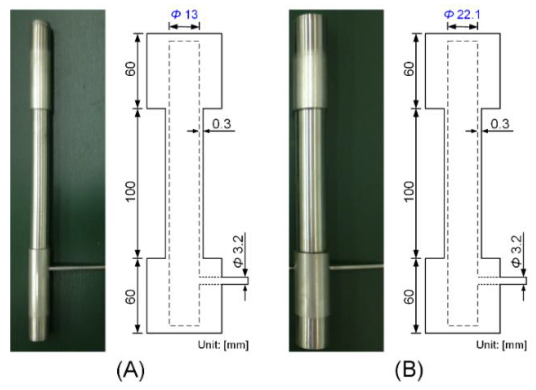
Figure 2 presents photographs of two cylindrical tube columns, along with schematics showing their dimensions. In this study, 304 stainless-steel tubes provided by Nilaco Corp. (Tokyo, Japan) were used. The chemical compositions of the SS-304 tubes are presented in Table 1. As shown in Figure 2, the tube columns consisted of two sections: A testing part and holder parts. The testing part was the middle of the columns and buckled under the external pressure load. The holder parts were the upper and lower parts of the testing part, which were connected to the electrodes via special holders. The two tube columns had the same dimensions, except for the diameter. The tube columns in Figure 2A,B were denoted as Tube 1-03 and Tube3-03, respectively. Tube1-03 had an inner diameter of 13 mm and a thickness of 0.3 mm in the testing part. The inner diameter and the thickness of the holder parts for Tube1-03 were 13 and 1 mm, respectively. Tube 3-03 had an inner diameter of 22.1 mm and a 0.3-mm thickness of the testing part. The outer diameter of the holder parts was 25.4 mm, and the inner diameter was equal to that of the testing part. The length of the testing part was 100 mm for both the tubes. Table 2 presents the dimensions of the tube columns tested in this study. As shown in Figure 2, a small stainless-steel pipe 3.2 mm in diameter was inserted into the lower holder part and welded to connect the inside of the tube to the outside of the pressure chamber (atmosphere). Thus, the atmospheric pressure (1 atm) was maintained inside the tube during the experiment.
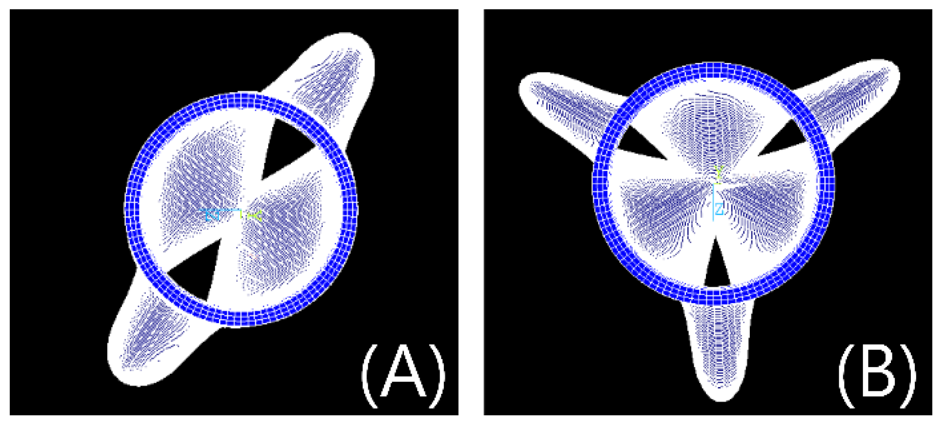
According to a previous study [13], the buckling mode induced by a radial pressure load is determined by the dimensions of the tube columns, i.e., the radius-to-thickness ratio (R/t) and length-to-radius ratio (L/R). As shown in Table 2, the two tube columns (Tube 1-03 and Tube 3-03) had different R/t and L/R values. The R/t values of Tube 1-03 and Tube 3-03 were 22.2 and 37.3, respectively. The L/R values of Tube 1-03 and Tube 3-03 were 15.0 and 8.9, respectively. Accordingly, Tube 1-03 buckled in the first mode, where two circumferential waves were formed; thus, the tube column was compressed in two opposite directions. In contrast, Tube 3-03 buckled in the second mode, where three circumferential waves were generated; thus, the tube column was deformed in three different directions. The two buckling modes were compared using the commercial finite element software ANSYS (mechanical APDL 14.0: element type: Solid185, Tokyo, Japan) as shown in Figure 3.
The simple procedures for the creep-buckling experiment are summarized as follows.
- A tube column was vertically mounted between the copper electrodes in the pressure chamber.
- The chamber was pressurized to a target value to apply the external pressure to the tube radially.
- The temperature of the tube column was quickly increased to an experimental condition (800, 900, and 1000 °C).
- The temperature and pressure were maintained during the test.
- The time taken for the tube to exhibit creep buckling (creep-buckling failure time) was measured.
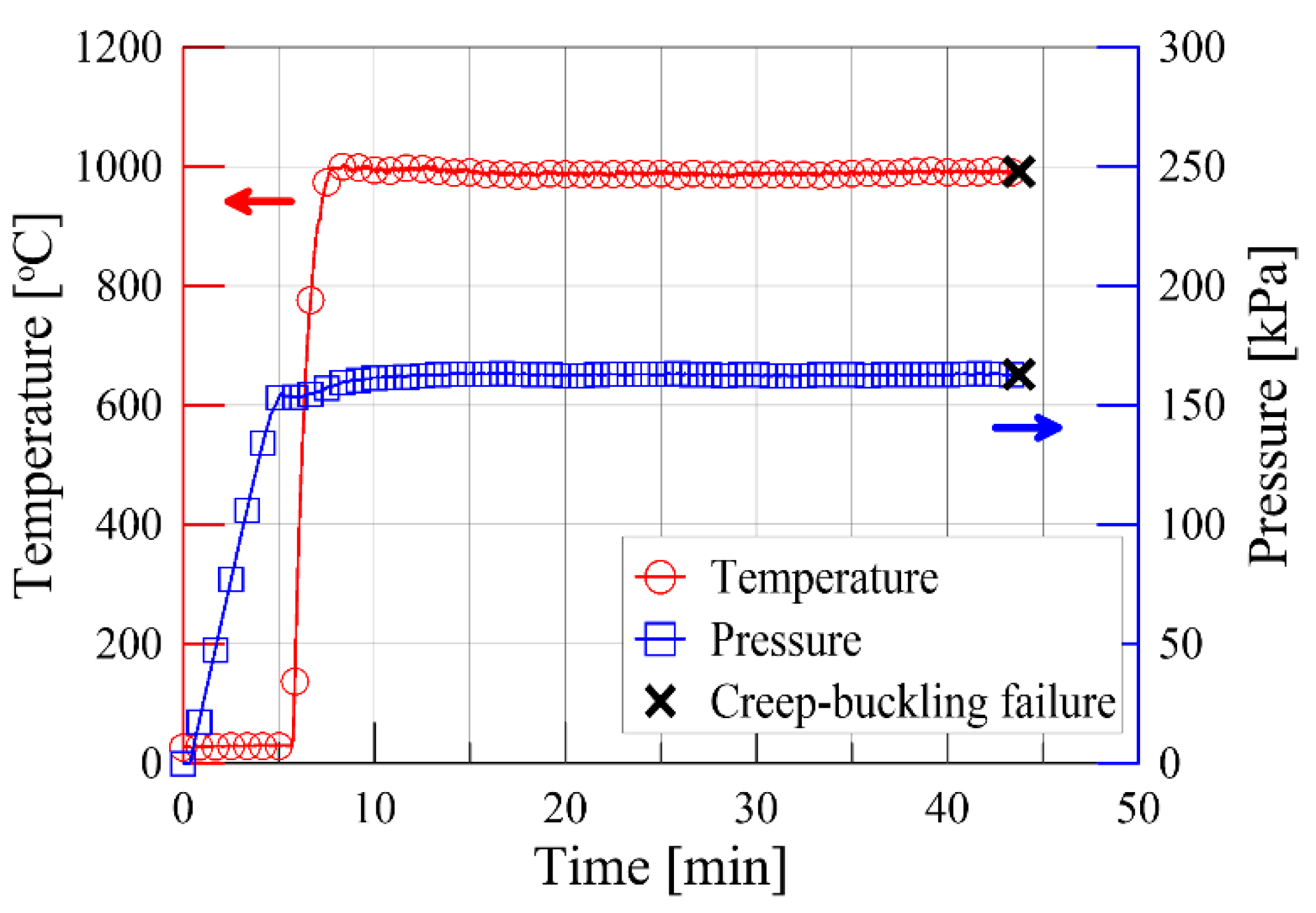
The temperature was increased by manually controlled voltages of the DC power supply. Because the buckling occurred in a short time, the temperature measured at the center deviated from the temperatures of the upper and lower (±20 mm from the center) thermocouples. However, in our previous study, the vertical temperature profile was uniform in creep-buckling experiments because of the long experimental duration. Additionally, in this study, the maximum deviation of the average temperature measured by three thermocouples for all of the tests was 2.0%. Figure 4 shows the typical temperature and pressure profiles obtained from the creep-buckling experiment of the present study. The time periods for the transient regions of the temperature (temperature-increasing regions) were not identical among the experiments, because the temperature was manually controlled. Nevertheless, the effect of the transient period was minimized by increasing the temperature. The transient heating time varied from approximately 1.3 to 8.2 min (average value: 3.7 min). These times are shorter than the creep-buckling failure time of the tube columns. The time period when the temperature of the tube column exceeded 700 °C was not significant for estimating the creep-buckling time. Hence, in the present study, the transient heating time was neglected in the estimation of the creep-buckling failure time.
3. Measurement Uncertainty
There were several measurement uncertainties for the creep-buckling failure time, temperature, and pressure in this study. The measurement uncertainty for the creep-buckling failure time was easily quantified, because the buckling failure of the tube column induced by the creep progressed quickly, and the deformation process was recorded by two cameras. According to the recording speed of 1 fps, the maximum measurement uncertainty for the creep-buckling failure time was obtained as 2.9%. The uncertainty of the pressure measurement was 0.5% according to the specifications of the pressure transducer. According to the 0.5 °C error of the K-type thermocouple, the uncertainty for the temperature measurement was negligible, because the minimum temperature was approximately 800 °C. However, as mentioned previously, the vertical temperature profile of the tube column was not uniform, because of the conduction heat loss in both the upper and lower copper electrodes. Nevertheless, temperature uniformity in the vertical direction of the tube column was achieved for most of the tested part of the specimen. Figure 5 compares the vertical temperature profiles for Tube1-03 between the experimental measurements and numerical predictions made using ANSYS. As the temperature increased, temperature uniformity was achieved for a greater length of the tube specimen. This is attributed to the longer time needed for the creep deformation to induce the failure (buckling) of the tube specimen.
4. Results and Discussions
4.1. Visualization of Creep-Buckling Deformation
Figure 6 and Figure 7 show the time evolution of the creep-buckling deformation of Tube 1-03 at 800 °C and Tube 3-03 at 1000 °C, respectively. As mentioned above, it was experimentally confirmed that Tube 1 and Tube 3 buckle in the first and second mode of buckling. In other words, Tube 1 was compressed from two opposite directions as generating two circumferential waves. Additionally, in spite of the creep-buckling, buckling occurred very quickly; less than in 1 s. However, gradual deformation was also captured as shown in Figure 6. A white vertical line (reflection of the lamp) on the tube column was bent slowly, but it was clearly observed. Eventually, the deformation initially began at the center of the column and then, spread in both vertical directions. Similar features were observed for Tube 3-03 which buckled in the second mode. At 300 s, a white vertical light was observed on the left side of the column, but it was faded out as time goes by. Finally, the initial deformation of the creep-buckling was formed right at the white line. Thus, it means that the creep deformation proceeded slowly but obviously.
4.2. Creep-Buckling Failure Time
Figure 8 and Figure 9 show experimental measurements of the creep-buckling failure time, which was the time required for the tube column to buckle owing to the creep effect under radial external pressure loading lower than the buckling pressure at a given temperature. Figure 8 shows the results for Tube 1-03. As indicated by the plot with linear axes in Figure 8A, the failure time exponentially increased with the decrease of the external pressure; thus, the curve fit appeared to follow a decreasing log function ( where C is a constant). At 800 °C, the tube column was sustained for approximately 50 min under a load of 88% of the buckling pressure. When the external pressure was reduced to 80% of the buckling pressure, the specimen buckled at approximately 224 min. A similar but distinguishable trend of the creep-buckling failure time was observed in the cases of 900 and 1000 °C. At these temperatures, the failure time did not rapidly increase with the large decrease of the external pressure. For example, at 900 °C, the failure time for a load of approximately 61% of the buckling pressure was approximately 27 min. However, the failure time of the tube column subjected to approximately half of the buckling pressure was 59 min, which is more than double the failure time for the 61% loading case. Furthermore, the failure time was measured to be 133 min for a load of 43% of the buckling pressure at 900 °C. Therefore, the curve fits for the creep-buckling failure time at 900 and 1000 °C appeared to follow the decreasing log function more rapidly than those for 800 °C. This feature is clearly indicated by the logarithmic plot in Figure 8B. Linear behaviors of the creep-buckling failure time were observed, as shown in Figure 8B, and the slopes of the curve fits for 900 and 1000 ℃ were larger than that for 800 °C.
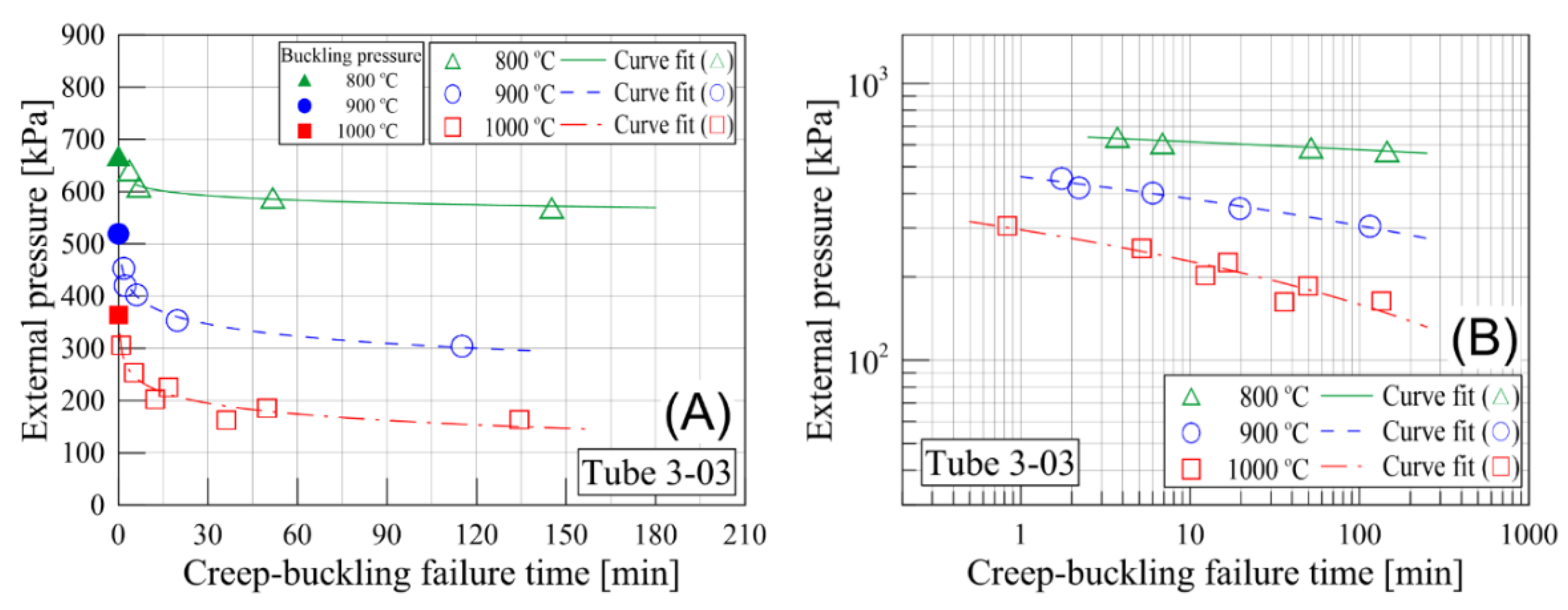
The creep-buckling failure time for Tube 3-03 is plotted in Figure 9. Because Tube 3-03 had a larger radius-to-thickness ratio than Tube 1-03, it deformed in a different buckling mode (second mode). However, the relationship between the external pressure and the failure time was similar to that for Tube 1-03. The failure-time increment with the decrease of the external pressure was more drastic at 800 °C than at 900 and 1000 °C. As indicated by the plots with logarithmic axes in Figure 9B, the slopes of the curve fits obtained at 900 and 1000 °C were larger than that for 800 °C.
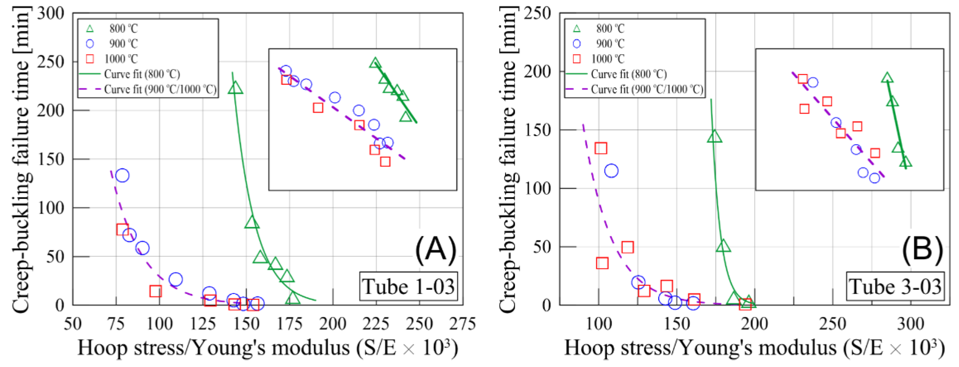
The temperature-dependent creep-buckling features can be explained by the variations of the creep-buckling failure time with respect to the circumferential stress (hoop stress) normalized by the Young’s modulus at each temperature. Figure 10 shows the variations of the creep-buckling failure time with respect to the circumferential stress (S) normalized by the Young’s modulus (E) for Tube 1-03 (Figure 10A) and Tube 3-03 (Figure 10B). The circumferential stress values were estimated at the inner radius using Equation (1), according to the external pressures.
Here, Pi and Po represent the pressures inside and outside the tube, respectively. ri and ro represent the inner and outer radii of the tube, respectively. The circumferential stress was normalized by the Young’s modulus at each temperature [14]. The failure times in Figure 10 are classified into two groups—800 °C and 900/1000 °C —regardless of the buckling mode (tube dimension). For both tubes, the 800 °C group exhibits larger S/E values than the 900/1000 °C group, because of the high external pressures. The failure time for 800 °C drastically increased with the decrease of the S/E value. In contrast, the failure time for the 900/1000 °C group exhibited a relatively moderate increase with the decrease of the S/E value. This characteristic is clearly indicated by the graphs in the insets (logarithmic axes) of Figure 10.
The two groups of the creep-buckling failure time in Figure 10 are attributed to change of the microstructures of the SS-304 specimens. A recrystallization process may have occurred in the specimens during the creep-buckling tests at 900 and 1000 °C. Thus, the microstructures of the austenitic stainless steel changed, and the grain size of the SS-304 tubes increased [15,16]. Since the failure time (duration of the tests) widely varied in this study from less than 1 min to more than 3 hours, the changes in the grain size might not be identical in all specimens. Nevertheless, the distinct relation between the failure time and the S/E value was obtained for the different buckling modes of the SS-304 tube specimens, as shown in Figure 10. Thus, it is postulated that the microstructures of the SS-304 were changed in the tests at 900 and 1000 °C. It is well known that the grain size of austenitic stainless steel is proportional to the heat-treatment temperature. Moreover, the strength of the stainless steel increases with the decrease of the grain size [16,17,18]. Bregliozzi et al. experimentally determined that the grain size of SS-304 varied according to the annealing temperature [15]. The average grain sizes were 2.5 and 40 μm for annealing temperatures of 780 and 1100 °C, respectively. Additionally, Schino et al. reported that the grain size of SS-304 was determined by both the annealing temperature and duration [16]. That is, the different microstructures based on the different grain sizes of SS-304 divided the creep-buckling behaviors of the cylindrical tubes under the external pressure into two groups. Similarly, the lattice self-diffusion coefficient of the SS-304 explains the effect of the temperature on the behaviors of the creep-buckling failure time. The diffusion coefficient is expressed by Equation (2), considering the temperature.
Here, DL, D0, k, Tm, and T represent the lattice self-diffusion coefficient, the experimental diffusion prefactor, a constant for a given crystal structure, the melting temperature, and the temperature of the specimen. The lattice self-diffusion coefficient decreases with the increase of the temperature. The strain rate ( is proportional to the lattice self-diffusion coefficient, as shown in Equation (3). A and b are a constant for a given material and the magnitude of the Burgers vector, respectively. SS-304 has a high diffusion coefficient under high-temperature conditions; accordingly, the strain rate increases with the temperature, and the failure time decreases for specimens at high temperatures. Ultimately, this may result in a nonlinearly decreasing Young’s modulus of SS-304 above 800 °C [13].
4.3. Empirical Correlation: LMP
Several parametric models have been proposed for predicting the long-term failure time based on short-term measurement data [19,20,21]. The LMP model and the Monkman–Grant model are widely used for the estimation of the creep-buckling failure time [12,22,23,24]. These models are both based on experimental measurements, but the Monkman–Grant model needs the minimum strain rate of the specimen. Hence, the LMP model was employed to propose an empirical correlation for the prediction of the creep-buckling failure time. In the LMP method, first, the LMP is calculated using experimental measurements (temperature and failure time), as shown in Equation (4), where T is the temperature, tc is the creep-buckling failure time, and K is the Larson–Miller constant for a given material. In this study, K was assumed to be 20 for the SS-304 [12,25].
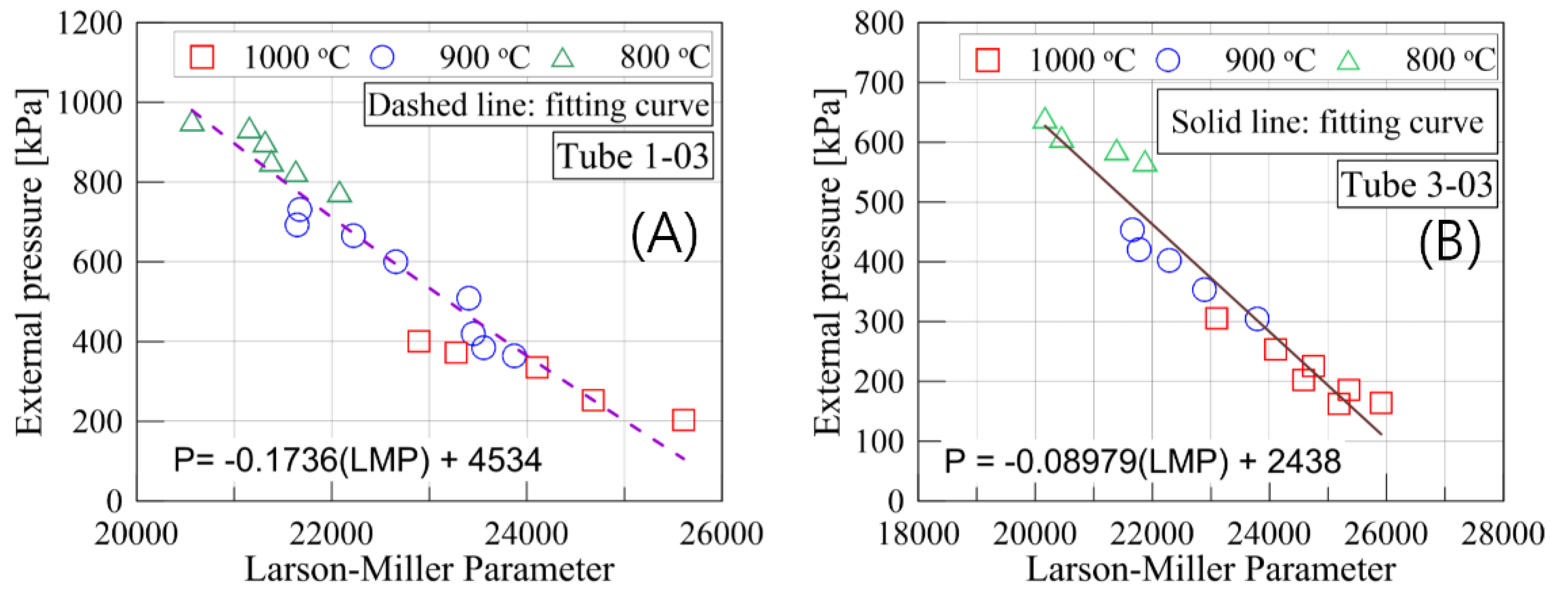
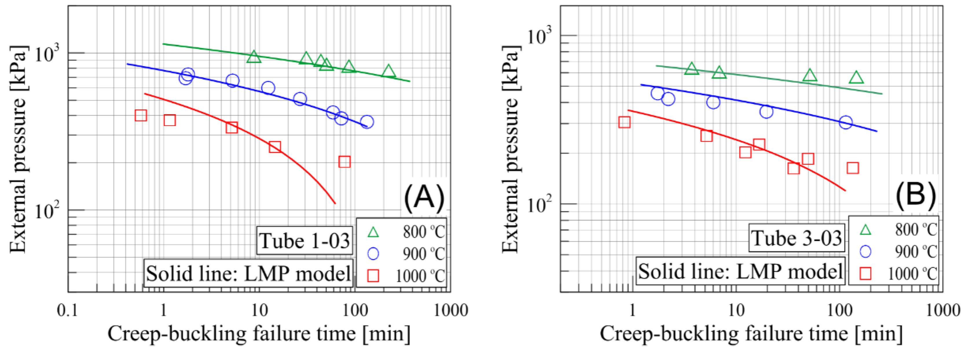
Figure 9B and Figure 11A show the LMP variations with respect to the external pressure for Tube 1-03 and Tube 3-03, respectively. As noted in each figure, the mathematical relationships between the LMP and the external pressure were obtained from the curve fits (P in the curve-fit equations represents the external pressure). The creep-buckling failure time for each tube column was obtained using Equation (4) and the curve fit. Equations (5) and (6) give the empirical correlations for predicting the creep-buckling failure time at a given temperature and external pressure for Tube 1-03 and Tube 3-03, respectively. According to the empirical correlations (Equations (5) and (6)), the creep-buckling failure time was estimated for the two tube columns at 800, 900, and 1000 °C with the variation of the external pressure and was compared with the experimental measurements in Figure 12. The prediction of the failure time by the LMP models was sufficiently accurate to elucidate the long-term behaviors of the tube columns subjected to the external pressure. However, in the case of Tube 1-03 at 1000 °C, the difference between the prediction and the measurement drastically increased with the decrease of the external pressure. The tendency of the prediction curve is strongly dependent on the mathematical model of the curve fit chosen for the LMP–external pressure relationship in Figure 11. Three parallel prediction lines can be produced by using a different curve-fit equation for the LMP–external pressure relationship. Therefore, additional measurements are necessary for more accurate prediction of the creep-buckling failure time using the LMP-based empirical correlation.
5. Conclusions
The creep buckling of thin cylindrical tube columns made of 304 stainless steel subjected to an external pressure at 800, 900, and 1000 °C was experimentally investigated for two different buckling modes. The interesting temperature dependent creep-buckling characteristic (failure time) was obtained in this study. The empirical correlations for predicting the failure time of the tube column were developed for each tube dimension based on the experimental measurements. According to the results of the experimental study and the analysis, the following conclusions are drawn.
- (a)
- The creep-buckling failure time for varying the external pressure is significantly affected by the temperature. For Tube 1-03, the failure time was measured to be >145 min for loading of 85% of the buckling pressure at 800 °C. However, the failure time under a similar external pressure (approximately 84% of the buckling pressure) was >1 min for Tube 1-03 at 1000 °C.
- (b)
- The relationships between the failure time and the circumferential stress normalized by the Young’s modulus (S/E) differed significantly between 800 and 900 °C. The experimentally-measured failure time was divided into two groups (800 °C and 900/1000 °C) as a function of the ratio of the circumferential stress to the Young’s modulus at each temperature. The increase of the failure time caused by the decrease of the S/E value was more drastic at 800 °C than 900/1000 °C.
- (c)
- LMP-based empirical correlations were developed for the two tube columns, and the prediction of the failure time agreed with the measurements. According to the mathematical model of the curve fit for the LMP–external pressure relationship, the temperature sensitivity of the failure-time predictions using the empirical correlations increased with the temperature.
Author Contributions
Conceptualization, K.O. and N.K.; methodology, B.J.; formal analysis, B.J., K.O., N.K.; investigation, B.J., K.O. and N.K.; writing—original draft preparation, B.J.; writing—review and editing, B.J.
Acknowledgments
This study was conducted as part of the “Study on failure mechanism of nuclear components under ultimate loadings and prevention of catastrophic failure modes” entrusted to the University of Tokyo by the Ministry of Education, Culture, Sports, Science and Technology of Japan (MEXT).
Conflicts of Interest
The authors declare no conflict of interest.
References
- Majumdar, S. Prediction of structural integrity of steam generator tubes under severe accident conditions. Nucl. Eng. Des. 1999, 194, 31–55. [Google Scholar] [CrossRef]
- Zinkle, S.J.; Was, G.S. Materials challenges in nuclear energy. Acta Mater. 2013, 61, 735–758. [Google Scholar] [CrossRef]
- Takahashi, Y.; Shibmoto, H.; Inoue, K. Study on creep-fatigue life prediction methods for low-carbon nitrogen-controlled 316 stainless steel (316FR). Nucl. Eng. Des. 2008, 238, 322–335. [Google Scholar] [CrossRef]
- Baddoo, N.R. Stainless steel in contruction: A review of research, applications, challenges and opportunities. J. Constr. Steel Res. 2008, 64, 1199–1206. [Google Scholar] [CrossRef]
- Brinkman, C.R.; Korth, G.E.; Hobbins, R.R. Estimates of creep-fatigue interaction in irradiated and unirradiated austenitic stainless steels. Nucl. Technol. 1972, 16, 297–307. [Google Scholar] [CrossRef]
- Wareing, J. Creep-fatigue interaction in austenitic stainless steels. Metall. Mater. Trans. A 1977, 8, 711–721. [Google Scholar] [CrossRef]
- Furumura, F.; Ave, T.; Kim, W.J. Creep buckling of steel columns at high temperatures Part II Creep buckling tests and numerical analysis. J. Str. Constr. Eng. 1986, 361, 142–151. [Google Scholar]
- Huang, Z.F.; Tan, K.H.; Ting, S.K. Heating rate and boundary restraint effects on fire resistance of steel columns with creep. Eng. Str. 2006, 28, 805–817. [Google Scholar] [CrossRef]
- Kobayashi, H.; Ohki, R.; Takamoto, I.; Masao, S. Multiaxial creep damage and lifetime evaluation under biaxial and triaxial stresses for type 304 stainless steel. Eng. Fract. Mech. 2017, 174, 30–43. [Google Scholar] [CrossRef]
- Jo, B.; Sagawa, W.; Okamoto, K. Buckling behaviors of metallic columns under compressive load at extremely high temperatures, In Proceedings of the ASME 2014 Pressure Vessels and Piping Conference, Anaheim, CA, USA, July 20–24, 2014.
- Jo, B.; Sagawa, W.; Okamoto, K. Measurement of buckling load for metallic plate columns in severe accident conditions. Nucl. Eng. Des. 2014, 274, 118–128. [Google Scholar] [CrossRef]
- Jo, B.; Okamoto, K. Experimental investigation into creep buckling of a stainless steel plate column under axial compression at extremely high temperatures. J. Press. Vessel Technol. 2017, 139, 011406. [Google Scholar] [CrossRef]
- Jo, B.; Kasahara, N.; Okamoto, K. Buckling of cylindrical stainless-steel tubes subjected to external pressure at extremely high temperatures. Eng. Fail. Anal. 2018, 92, 61–70. [Google Scholar] [CrossRef]
- Kasahara, N. Report for the MEXT Nuclear System Research Project, Study on Failure Mechanism of Nuclear Components Under Ultimate Loadings and Prevention of Catastrophic Failure Modes; Ministry of Education, Culture, Sports, Science and Technology: Tokyo, Japan, 2016. (In Japanese)
- Bregliozzi, G.; Ahmed, S.I.U.; Schino, A.D.; Kenny, J.M.; Haefke, H. Friction and wear behavior of austenitic stainless steel: influence of atmospheric humidity, load range, and grain size. Tribol. Lett. 2004, 17, 697–704. [Google Scholar] [CrossRef]
- Schino, A.D.; Barteri, M.; Kenny, J.M. Effects of grain size on the properties of a low nickel austenitic stainless steel. J. Mater. Sci. 2003, 38, 4725–4733. [Google Scholar] [CrossRef]
- Wang, N.; Wang, Z.; Aust, K.T.; Erb, U. Effect of grain size on mechanical properties of nanocrystalline materials. Acta Metall. Mater. 1995, 43, 519–528. [Google Scholar] [CrossRef]
- Lee, Y.S.; Kim, D.W.; Lee, D.Y.; Ryu, W.S. Effect of grain size on creep properties of type 316LN stainless steel. Met. Mater. Int. 2001, 7, 107–114. [Google Scholar] [CrossRef]
- Larson, F.R.; Miller, J. A time-temperature relationship for rupture and creep stresses. Trans. ASME 1952, 74, 765–771. [Google Scholar]
- Orr, R.L.; Sherby, O.D.; Dorn, J.E. Correlation of rupture data for metals at elevated temperatures. Trans. ASME 1954, 46, 113–128. [Google Scholar]
- Monkman, F.C.; Grant, N.J. An empirical relationship between rupture life and minimum creep rate in creep rupture test. Proc. ASTM 1956, 56, 593–620. [Google Scholar]
- Sundararajan, G. The Monkman-Grant relationship. Mat. Sci. Eng. A 1989, 112, 205–214. [Google Scholar] [CrossRef]
- Fedoseeva, A.; Dudova, N.; Kaibyshev, R.; Belyakov, A. Effect of tungsten on creep behavior of 9%Cr—3%Co martensitic steels. Metals 2017, 7, 573. [Google Scholar] [CrossRef]
- Dewa, R.T.; Park, J.H.; Kim, S.J.; Lee, S.Y. High-temperature creep-fatigue behavior of alloy 617. Metals 2018, 8, 103. [Google Scholar] [CrossRef]
- Masuyama, F. Creep rupture life and design factors for high-strength ferritic steels. Int. J. Pres. Vessel. Pip. 2007, 84, 53–61. [Google Scholar] [CrossRef]
Figure 1.
Schematic of the experimental setup.

Figure 2.
Photographs and dimensions of two tube specimens: (A) Tube1-03 and (B) Tube3-03.

Figure 3.
Comparison of the buckling modes. Top views of the specimens: (A) Tube 1-03 and (B) Tube 3-03.
Figure 3.
Comparison of the buckling modes. Top views of the specimens: (A) Tube 1-03 and (B) Tube 3-03.

Figure 4.
Typical temperature and pressure behaviors during the creep-buckling experiment.

Figure 5.
Comparison of the vertical temperature profiles of Tube 1-03 between the experimental measurements and numerical predictions.
Figure 5.
Comparison of the vertical temperature profiles of Tube 1-03 between the experimental measurements and numerical predictions.

Figure 6.
Time evolution images of the creep-buckling deformation (Tube 1-03 at 800 °C).

Figure 7.
Time evolution images of the creep-buckling deformation (Tube 3-03 at 1000 °C).

Figure 8.
Measurements of the creep-buckling failure for Tube 1-03: (A) linear horizontal axis and (B) logarithmic horizontal axis.
Figure 8.
Measurements of the creep-buckling failure for Tube 1-03: (A) linear horizontal axis and (B) logarithmic horizontal axis.

Figure 9.
Measurements of the creep-buckling failure for Tube 3-03: (A) Linear horizontal axis and (B) logarithmic horizontal axis.
Figure 9.
Measurements of the creep-buckling failure for Tube 3-03: (A) Linear horizontal axis and (B) logarithmic horizontal axis.

Figure 10.
Variation of the creep-buckling failure time with respect to the circumferential stress (hoop stress) normalized by the Young’s modulus (small window: Logarithmic axes): (A) Tube 1-03 and (B) Tube 3-03.
Figure 10.
Variation of the creep-buckling failure time with respect to the circumferential stress (hoop stress) normalized by the Young’s modulus (small window: Logarithmic axes): (A) Tube 1-03 and (B) Tube 3-03.

Figure 11.
LMP variations with respect to the external pressure for (A) Tube 1-03 and (B) Tube 3-03.
Figure 11.
LMP variations with respect to the external pressure for (A) Tube 1-03 and (B) Tube 3-03.

Figure 12.
Prediction of the creep-buckling failure time using the LMP models (symbols: Experimental measurements) for (A) Tube 1-03 and (B) Tube 3-03.
Figure 12.
Prediction of the creep-buckling failure time using the LMP models (symbols: Experimental measurements) for (A) Tube 1-03 and (B) Tube 3-03.


Table 1.
Chemical composition of SS-304 (mass fraction, %).
| C | Si | Mn | P | S | Ni | Cr |
|---|---|---|---|---|---|---|
| 0.003 | < 1.0 | < 2.0 | 0.045 | < 0.03 | 8-11 | 18–20 |
Table 2.
Dimensions of the two tube columns tested in this study.
| Specimen Name | Inner Diameter [mm] | Thickness a [mm] | Length a [mm] | Radius-to-Thickness Ratio (R/t) b | Length-to-Radius Ratio (L/R) b |
|---|---|---|---|---|---|
| Tube 1-03 | 13.0 | 0.3 | 100 | 22.2 | 15.0 |
| Tube 3-03 | 22.1 | 0.3 | 100 | 37.3 | 8.9 |
a Testing part of tube columns; b Mean radius was used to determine R/t and L/R values.
© 2019 by the authors. Licensee MDPI, Basel, Switzerland. This article is an open access article distributed under the terms and conditions of the Creative Commons Attribution (CC BY) license (http://creativecommons.org/licenses/by/4.0/).
Share and Cite
MDPI and ACS Style
Jo, B.; Okamoto, K.; Kasahara, N. Creep Buckling of 304 Stainless-Steel Tubes Subjected to External Pressure for Nuclear Power Plant Applications. Metals 2019, 9, 536. https://doi.org/10.3390/met9050536
AMA Style
Jo B, Okamoto K, Kasahara N. Creep Buckling of 304 Stainless-Steel Tubes Subjected to External Pressure for Nuclear Power Plant Applications. Metals. 2019; 9(5):536. https://doi.org/10.3390/met9050536
Chicago/Turabian StyleJo, Byeongnam, Koji Okamoto, and Naoto Kasahara. 2019. "Creep Buckling of 304 Stainless-Steel Tubes Subjected to External Pressure for Nuclear Power Plant Applications" Metals 9, no. 5: 536. https://doi.org/10.3390/met9050536
Note that from the first issue of 2016, this journal uses article numbers instead of page numbers. See further details here.