Induction Skull Melting of Ti-6Al-4V: Process Control and Efficiency Optimization


Mechanical and Manufacturing Department, Mondragon University, Loramendi 4, 20500 Mondragon, Gipuzkoa, Spain
*
Author to whom correspondence should be addressed.
Metals 2019, 9(5), 539; https://doi.org/10.3390/met9050539
Submission received: 15 April 2019
/
Revised: 3 May 2019
/
Accepted: 8 May 2019
/
Published: 10 May 2019
(This article belongs to the Special Issue New Processes and Machine Tools for Advanced Metal Alloys)
Abstract
:Titanium investment casting is one of the leading and most efficient near-net-shape manufacturing processes, since complex shape components are possible to obtain with a very low amount of material waste. But melting these reactive alloys implies the usage of specific melting technologies such as the Induction Skull Melting (ISM) method. In this work the ISM was extensively studied with the aim of deepening the characteristics of this specific melting method and improving the too low energy efficiency and overall process performance. A 16 segment copper crucible and 3 turns coil was employed for the melting of 1 kg of Ti-6Al-4V alloy. Through the calorimetric balance, real-time evolution of the process parameters and power losses arising from the crucible and coil sub-assemblies was displayed. Results revealed the impact of coil working conditions in the overall ISM thermal efficiency and titanium melt properties, revealing the use of these conditions as an effective optimization strategy. This unstudied melting control method allowed more heat into charge and 13% efficiency enhancement; leading to a shorter melting process, less energy consumption and increased melt superheat, which reached 49 °C. The experimental data published in this paper represent a valuable empiric reference for the development and validation of current and future induction heating models.
1. Introduction
The upward trend for titanium and intermetallic TiAl alloy employment in new commercial aircrafts is one of the main reasons for CO2 and NOx emission reductions [1,2], since these lightweight materials function effectively in high-temperature and corrosive environments [3,4]. The direct impact of this increasing demand on the manufacturing technologies is evident, which productivity and cost must keep under control to bring competitive products [5].
In the last decade, additive manufacturing (AM) processes have been getting more attention for the manufacturing of complex Ti-6Al-4V and TiAl components in aeronautics [6,7,8]. Nevertheless, melting route is also in demand because of its remarkable mass production and price reduction. This fact is mainly due to the implementation of the Induction Skull Melting (ISM) for the melting of such alloys [2]. An additional contribution to cost savings is the introduction of the recycling technology for TiAl revert [9]. However, the industry has to overcome some challenging issues (accuracy of chemical composition, microstructural homogeneity, etc.) that require a good control over melting variables [10].
1.1. ISM Technology
The ISM facility, also known as Cold Crucible Induction Melting (CCIM), is composed of a vacuum chamber in which the induction melting is performed under controlled atmosphere conditions, vacuum or inert gas [11]. The copper crucible is made of electrically insulated segments, among which magnetic fields supplied by the induction coil penetrate to the charge, heating and melting by the Joule effect (Figure 1). Since the crucible is water-cooled, as the alloy melts a layer of solidified metal, known as the “skull”, forms between the crucible and the liquid metal, preventing contamination of the alloy [12,13]. Additional melt protection is achieved through the magnetic melt confinement.
Low energy efficiency is one of the principal drawbacks of this melting method, since most of heat induced into charge is being lost from crucible cooling system. As Pericleous et al. reported for melting of an aluminum charge, about 50% to 54% of the input power is being lost because of the water-cooled crucible [15]. Thus, limited melt superheat (33 °C to 62 °C) [16] is an important consequence of low process efficiency [17], reducing metal castability and increasing the probability of casting defects into final parts [18]. However, despite the relevance of the ISM technology in conventional titanium and TiAl alloy castings, the amount of published operating data relating to cold wall melting is not extensive [19].
Some works have focused on studying the optimum operating conditions and geometry of the cold crucible [20], but fewer referred to the power losses arising from the induction coil [21]. In this regard, calorimetric balance is a commonly employed thermal efficiency characterization method for the induction melting processes [14,15,17,21,22,23], but has not been applied in depth to study the ISM.
Many studies have also focused on the ISM numeric simulation [13,17,24,25,26], analyzing the effect of different process parameters to identify and propose the most effective optimization strategy (influence of crucible and coil design [23], power and frequency supplied to the coil, melting atmosphere [27], etc.). However, most of these models are still under empirical validation. Only few works, such as that of Bulinski et al., develop and empirically correlate an ISM numeric model [26].
In the same manner, several works have demonstrated the advantage that metal casting simulation offers in the mold filling optimization and defect prediction [28,29,30,31]. However, since data input plays a key role in every casting model, a more accurate melt characterization will lead to improved defect prediction.
1.2. Research Objective and Plan
The present work overcomes a double gap in this matter. On one hand, the influence of the coil sub-assembly (coil + leads + coaxial port) on the overall ISM process efficiency is empirically revealed during the melting of 1kg of Ti-6Al-4V. This fact identifies optimization of the coil cooling conditions such as a very effective thermal efficiency optimization strategy; reducing energy losses, increasing the amount of heat absorbed by the charge and thus melt superheat. From the other hand, process data here revealed support for valuable scientific content which allows the empirical validation of current and future ISM and casting simulations. This work could also be a reference for the development of more accurate induction heating numeric models and represent the opening for several technology improvements for the modern industry.
In the present research first a Ti-6Al-4V melting trial is performed based on the stock operating conditions for the ISM facility. The evolution of most relevant process parameters are displayed in real-time in each ISM component sub-assembly. After the analysis of the process data and evolution, the most effective improvement method is proposed and performed. The data arising from the second melting are then analyzed and compared to that of the first trial, and different cause-effect phenomenon are described between power applied, power loss and charge temperature. Finally, the most relevant conclusions are exposed.
2. Materials and Methods
2.1. Calorimetric Balance Calculation
According to the calorimetric equation (Equation (1)) the total energy transmitted by power supply is not only used to melt the charge [24], as power losses appear both in crucible segments and coil due to the Joule effect. They also appear in leads and the coaxial port, and additional power loss occurs because of the charge radiation effect.
where:
Pch(t) = Pps (t) − Pcr (t) − Pco (t) − Ple (t) − Pcp (t) − Prad (t),
Pch is the power absorbed by the charge [W]
Pps is the power supplied by the generator [W]
Pcr is the power loss from the crucible [W]
Pco is the power loss from the coil [W]
Ple is the power loss from the leads [W]
Pcp is the power loss from the coaxial port [W]
Prad is the power loss from the charge-to-environment [W]
For the calculation of power losses arising from water cooled ISM components, such as the crucible, coil, leads and coaxial port, several cooling system data recording is required, according to the following Equation (2).
where:
P = Cp · ρ · V · ΔT
P is the power loss [W]
Cp is the specific heat capacity of the water [4.1813 J·gr−1·K−1]
ρ is the density of water [1000 gr·liter−1]
V is the water flow in each component [liters·sec−1]
ΔT is the water temperature difference in each component [°C]
For charge-to-environment heat loss estimation the Stefan-Boltzmann law is used as shown in Equation (3). Accordingly, in the work of Dumont et al. they estimated the radiating surface of charge such as a half of the total charge surface and took an emissivity of 0.4 for molten pure titanium (T40) [21].
where:
Prad = A · ε · σ · T4
Prad is the power radiated [W]
ε is the emissivity of the titanium
σ is the Stefan-Boltzmann constant [5.67 · 10−8 W·m−2·K−4]
T is the surface temperature of the charge [K]
For the calculation of overall thermal efficiency of the ISM power absorbed by the charge will be considered as a percentage of total power provided by the power supply Equation (4).
where:
η = (Pch (t)/Pps (t)) · 100,
η is the Efficiency [%]
Pch is the power absorbed by the charge [W]
Pps is the power supplied by the generator [W]
2.2. ISM Facility
A SECO/WARWICK semi-industrial scale ISM facility, with a 16 sector cylindrical copper crucible, 1 mm slit thickness was employed (Figure 2a). 348.4 cm3 volume was maximum crucible capacity. ZrSiO4 refractory grout was used to fill each slit and block liquid titanium entrapment, avoiding electrical short-circuits between copper fingers. A three-turn coil was installed wrapping the copper crucible. So as to allow a higher power efficiency and melt superheat, 18 Soft Magnetic Composite (SMC) shunts were settled to the outside of the coil. The coil was connected to coaxial port enabling melt-box tilting. Outside of the vacuum chamber, a coaxial lead connected coaxial port and a 100 kW and 10 kHz frequency solid state converter were installed, supplied by Alecto Systems LLC. (Solon, OH, USA). A single Parker-Hiross ICE (Cleveland, OH, USA) 116 kW chiller was used to refrigerate water arising from crucible and coil sub-assemblies (Figure 2b).
Two melting trials were performed, and real-time evolution of each process parameter was recorded. Two calorimetric flow sensors displayed the water flow of crucible and coil sub-assemblies and three resistance temperature detectors for the water temperature inlet and outlet monitoring (0.1% of error un the 0–200 °C measuring range). A two wavelength pyrometer that automatically corrects emissivity changes in a range of 700 °C to 1800 °C was used to control surface temperature of the titanium charge. 0.1 K of error must be considered for temperatures above 900 °C. The pyrometer was placed in the outside of vacuum chamber and measured the charge through a glass viewport. A correction of +31.5 °C must be added to the measure provided by pyrometer at temperatures close to the melting to display real melt superheat [12]. Two 4-channel universal analog input NI 9219 modules were used to acquire data from each sensor at 1 Hz.
2.3. Material Selection
In accordance with the aeronautic sector, the commercial Grade 5 titanium alloy (Ti-6Al-4V) was selected. This α + β alloy, with 6% in weight of aluminum and 4% of vanadium was developed in the 1950s and is commonly used for structural applications working under 400 °C, where high strength and corrosion resistance are also required. In the present research two commercial Ti-6Al-4V alloy bars of Ø 60 mm and 80 mm length were used as raw material for the melting trials (Table 1).
2.4. Process Parameters
For the first melting trial chiller threshold was set to the maximum available temperature of 33 °C in order to reduce thermal drift among charge and crucible, and thus minimize the skull mass (Table 2). To reduce the refrigerating water temperature variation 2 °C was defined for the chiller start-stop setting rank. Water flows for crucible and coil sub-assemblies were set in the maximum of 13 and 11 L per minute, respectively. In the second trial, chiller threshold was lowered to environmental 20 °C. However, a lower cooling temperature in crucible increases power losses and the unmelted skull mass. Thus, so as to keep constant the remaining skull for the second trial, the crucible cooling system water flow was reduced to 10 L per minute. As a consequence, coil water flow lowered to 8 L per minute.
2.5. Melting Procedure
Melting usually involved selecting progressively higher power with time, so the power profile was manually controlled. Initially 20 kW steps were applied to 60 kW, then decreased to 10 kW steps until 100 kW was reached. Charge temperature was the reference parameter for each power step increase. When the charge temperature stabilized and started to decrease, a power increase was applied. This strategy was maintained until the titanium charge melted.
Just before pouring, the power supply was turned off. The crucible was tilted and the melt was poured into a ceramic mold where it solidified. During the cooling process 100 mbar argon pressure was maintained for 45 min to reduce reactions between atmospheric oxygen and titanium alloy.
3. Results
3.1. Cooling System
In the first melting water outlet, temperature of crucible and coil increased according to the applied power steps. 77 °C and 95 °C were the respective maximum values (Figure 3a). In the second trial process the parameters were changed and chiller threshold was reduced to 20 °C in order to reduce the coil working temperature.
Results of the second trial showed that while the coil cooling system temperature was reduced to 76 °C, the crucible cooling system was maintained at 77 °C (Figure 3b). In this trial both temperatures, below 80 °C, were considered reliable for the ISM facility.
3.2. Power Distribution
The real-time power distribution (Figure 4a) of the first experiment revealed the upward trend of heat losses arising from crucible and coil sub-assemblies. As shown in Figure 4b, mean heat losses for coil and crucible sub-assemblies performed similarly, with both rising as the source power increased. However, heat losses of coil sub-assembly were always greater than those arising from the crucible cooling system; and the difference grew as higher power applied.
Moreover, energy absorbed by the charge reported sudden power increases during the first stage of each power step (Figure 4a), meaning a higher efficiency during this period. However, it decreased as the cooling systems responded due to great thermal inertia.
In the second trial, optimized cooling conditions allowed reducing power losses of coil sub-assembly, and thus heat absorbed by the charge increased (Figure 5). Power in the charge performed similarly in the second melt, increasing suddenly when each power step applied and decreasing toward the end of each holding period.
3.3. Process Efficiency
In Figure 6 furnace efficiency evolution is displayed for each experiment. In both trials, the previously expected temporary efficiency enhancement during each power step application was confirmed. However, the intensity of transient peaks diminished in line with the increasing power applied. Finally, the power exploitation resulted in less than 23% under melted conditions. The second trial efficiency trend performed similarly, but 13% greater than that of the first melt, reaching 36% in melting.
3.4. Power Profile and Charge Temperature
Figure 7 shows the relation among power applying strategy and charge temperature evolution. In the first trial 1654 °C was maximum temperature recorded by the pyrometer at 949 s, 6 °C below liquidus temperature of the alloy (1660 °C). After pyrometer drift correction a 25.5 °C superheat was predicted, supporting the evidence of the liquid phase alloy visualized through the recording camera.
In the second trial the temperature of the melt achieved 1678 °C, 24 °C more than the preceding melt result (Figure 7). However, after the pyrometer drift correction the temperature supported 1709 °C, and thus 49 °C became the maximum melt superheat. Concerning the time required to melt the titanium charge in the second trial diminished from 880 to 823 s.
4. Discussion
4.1. Cooling Temperature and Power Distribution
The analysis of the results obtained from the cooling water evolution and real-time power distribution demonstrate that lower coil temperature allowed more power into the charge, with respective effects in the evolution of the melting process. While the crucible temperature was maintained as constant, a reduction of 15 °C in the coil working conditions reduced the power lost from the coil sub-assembly. This fact inferred more power available for the charge and thus overall ISM efficiency raised from 23% to 36%. Therefore, 5700 kJ less energy was consumed at 100 kW of power applied, but also a more reliable and safe heating and melting process was accomplished.
4.2. Charge Temperature
The more reliable coil working conditions achieved in the second melting also influenced melt temperature; and thus overheating reached a maximum of 49 °C; 23.5 °C higher than the preceding trial. In addition, the time required to melt the titanium charge diminished by 1 minute.
4.3. Process Parameter Evolution
Since real-time evolution was displayed, the behavior of each process parameter and ISM efficiency were analyzed. In this matter, energy absorbed by the charge reported sudden power increases during the first stage of each power step applied, meaning a higher efficiency was obtained during this short period. However, the efficiency peak decreased as well as the cooling systems response due to greater thermal inertia. The phenomena here also revealed the affected charge temperature, whose heating range increased quickly and reduced as the thermal inertia of the cooling system gained more relevance. This temperature behavior also linked with previously analyzed efficiency profile where power in the charge stabilized and started to decrease toward the end of each power step-holding period.
5. Conclusions
The results obtained in this research highlight the relevance of the coil working conditions for melting of titanium alloys in a real ISM facility. Optimized cooling conditions for coil sub-assembly reduced the power losses and extensively increased process efficiency from 23% to 36%, but also shortened the melting time required by more than 1 min and increased the melt superheat to a maximum of 49 °C. More effective energy exploitation allowed an earlier titanium charge melting, reducing process lead-time and total energy consumption. In addition, the proposed ISM strategy reveals a new method that will lead to a more favorable melt fluidity to enhance complex geometry and thin-walled titanium casting obtaining. Finally, the valuable experimental data published in this paper are of great value for the scientific community since they represent an important empiric reference for the development, validation and improvement of current and future ISM and casting models.
Author Contributions
X.C. designed and performed the experiments, X.C. and D.B. analyzed the data obtained and wrote the paper. N.H.-D. and I.H. guided and supervised all the work carried out in this research.
Funding
This research received no external funding.
Acknowledgments
The authors would like to acknowledge the effort and support given by ALFA Idei S.L. to this research. In a like manner the authors acknowledge the Department of Education, Universities and Research of the Basque Government for its financial support.
Conflicts of Interest
The authors declare no conflict of interest. The founding sponsors had no role in the design of the study; in the collection, analyses, or interpretation of data; in the writing of the manuscript, and in the decision to publish the results.
References
- Michaels, D. New materials for airplanes. Wall Street J. Eur. Ed. 2013, June, 17. [Google Scholar]
- Güther, V.; Allen, M.; Klose, J.; Clemens, H. Metallurgical processing of titanium aluminides on industrial scale. Intermetallics 2018, 103, 12–22. [Google Scholar] [CrossRef]
- Tetsui, T. Manufacturing technology for gamma-TiAl alloy in current and future applications. Rare Met. 2011, 30, 294–299. [Google Scholar] [CrossRef]
- Chamorro, X.; Herrero-Dorca, N.; Rodríguez, P.P.; Andrés, U.; Azpilgain, Z. α-case formation in Ti-6Al-4V investment casting using ZrSiO4 and Al2O3 moulds. J. Mater. Process. Technol. 2016, 243, 75–81. [Google Scholar] [CrossRef]
- Aguilara, J.; Schievenbuschb, A.; Kattlitzc, O. Qualification of a casting technology for production of titanium aluminide components for aero-engine applications. Adv. Mater. Res. 2011, 278, 563–568. [Google Scholar] [CrossRef]
- Sabbadini, S. Electron beam melting of second and third generation TiAl alloys. In Proceedings of the 5th International Workshop on Titanium Aluminides, Tokyo, Japan, 28 August–2 September 2016. [Google Scholar]
- Voisin, T.; Monchoux, J.P.; Hantcherli, M.; Mayer, S.; Clemens, H.; Couret, A. Microstructure and mechanical properties of a multi-phase β-solidifying TiAl alloy densified by spark plasma sintering. Acta Mater. 2014, 73, 107–115. [Google Scholar] [CrossRef]
- Baudana, G.; Biamino, S.; Klöden, B.; Kirchner, A.; Weißgärber, T.; Kieback, B.; Pavese, M.; Ugues, D.; Fino, P.; Badini, C. Electron beam melting of Ti-48Al-Nb-0.7Cr- 0.3Si: feasibility investigation. Intermetallics 2016, 73, 43–49. [Google Scholar] [CrossRef]
- Güther, V.; Keitel, H.; Klose, J.; Rothe, C.; Eulitz, I. Development of an industrial recycling technology for TiAl revert. In Proceedings of the 5th International Workshop on Titanium Aluminides, Tokyo, Japan, 28 August–2 September 2016. [Google Scholar]
- Kamyshnykova, K.; Lapin, J. Vacuum induction melting and solidification of TiAl-based alloy in graphite crucibles. Vacuum 2018, 154, 218–226. [Google Scholar] [CrossRef]
- Yang, J.; Wang, H.; Wu, Y.; Wang, X.; Hu, R. A combined electromagnetic levitation melting, counter gravity casting, and mold preheating furnace for producing TiAl alloy. Adv. Eng. Mater. 2017, 20, 1–7. [Google Scholar] [CrossRef]
- Harding, R.A.; Wickins, M. Temperature measurements during induction skull melting of titanium aluminide. Mater. Sci. Technol. 2003, 19, 1235–1246. [Google Scholar] [CrossRef]
- Xue, G.; Wang, T.; Su, Y.; Cai, S.; Xu, J.; Li, J.; Guo, J.; Li, T. Numerical simulation of thermal and flow fields in induction skull melting process. Rare Met. Mater. Eng. 2009, 38, 761–765. [Google Scholar]
- Umbrashko, A.; Baake, E.; Nacke, B.; Jakovics, A. Experimental investigations and numerical modelling of the melting process in the cold crucible. COMPEL - The Int. J. Comput. Math Electr. Electron. Eng. 2005, 24, 314–323. [Google Scholar] [CrossRef]
- Pericleous, K.; Bojarevics, V.; Djambazov, G.; Harding, R.A.; Wickins, M. Experimental and numerical study of the cold crucible melting process. Appl. Math. Modell. 2006, 30, 1262–1280. [Google Scholar] [CrossRef]
- Harding, R.A.; Wickins, M.; Li, Y.G. Progress towards the production of high quality γ-TiAl castings. In Proceedings of the 3rd International Symposium on Structural Intermetallics, Jackson Hole, WY, USA, 28 April–2 May 2002; pp. 181–189. [Google Scholar]
- Bojarevics, V.; Harding, R.A.; Pericleous, K.; Wickins, M. The development and experimental validation of a numerical model of an induction skull melting furnace. Metall. Mater. Trans. B 2004, 35, 785–803. [Google Scholar] [CrossRef]
- Gomes, F.; Puga, H.; Barbosa, J.; Ribeiro, C.S. Effect of melting pressure and superheating on chemical composition and contamination of yttria-coated ceramic crucible induction melted titanium alloys. J. Mater. Sci. 2011, 46, 4922–4936. [Google Scholar] [CrossRef]
- Haun, R.; Charles, M.; Lampson, R.; Meese, P.; Nemkov, V.S.; Goldstein, R.; Kreter, K. Recent Design and Operational Developments of Cold Wall Induction Melting Crucibles for Reactive Metals Processing. Available online: https://fluxtrol.com/recent-design-and-operational-development-of-cold-wall-induction-melting-crucibles?utm_source=September&utm_medium=email&utm_campaign=FluxtrolEmail;2017 (accessed on 19 October 2017).
- Golak, S.; Przyłucki, R.; Smołka, J.; Bulinski, P.; Cieplinski, P. Influence of a cold crucible geometry parameters on electrical efficiency. Int. J. Appl. Electromagnet Mech. 2018, 56, 165–172. [Google Scholar] [CrossRef]
- Dumont, M.; Ernst, R.; Garnier, C.; Petitpas, P. Recent progresses in optimizing inductive cold crucible processes. In Proceedings of the 6th International Conference on Electromagnetic Processing of Materials, Dresden, Germany, 19–23 October 2009. [Google Scholar]
- Bojarevics, V.; Pericleous, K. Modeling induction skull melting design modifications. J. Mater. Sci. 2004, 39, 7245–7251. [Google Scholar] [CrossRef]
- Spitans, S.; Jakovics, A.; Baake, E.; Nacke, B. Numerical modelling of free surface dynamics of melt in induction crucible furnace. Magnetohydrodynamics 2010, 46, 317–328. [Google Scholar]
- Quintana, I. Numerical Modelling of Cold Crucible Induction Melting (Ccim) Process and Fabrication of High Value Added Components of Titanium and Its Alloys. Ph.D. Thesis, Mondragon Unibertsitatea, Guipuzkoa, Spain, 2013. [Google Scholar]
- Nemkov, V.; Goldstein, R.; Kreter, K.; Jackowski, J. Modeling and Optimization of Cold Crucible Furnaces for Melting Metals. In Proceedings of the International Symposium Heating by Electromagnetic Sources 2013, Padua, Italy, 21–24 May 2013. [Google Scholar]
- Bulinski, P.; Smolka, J.; Golak, S.; Przylucki, R.; Palacz, M.; Siwiec, G.; Melka, B.; Blacha, L. Numerical modelling of multiphase flow and heat transfer within an induction skull melting furnace. Int. J. Heat Mass Transf. 2018, 126, 980–992. [Google Scholar] [CrossRef]
- Ruirun, C.; Jieren, Y.; Hongsheng, D.; Feng, H.; Yanqing, S.; Jingjie, G.; Hengzhi, F. Effect of power parameter and induction coil on magnetic field in cold crucible during continuous melting and directional solidification. China Foundry 2012, 1, 15–19. [Google Scholar]
- Yang, J.; Wang, H.; Wu, Y.; Zhang, K.; Wang, X.; Hu, R. Numerical calculation and experimental evaluation of counter-gravity investment casting of Ti-48Al-2Cr-2Nb alloy. Int. J. Adv. Manuf. Technol. 2018. [Google Scholar] [CrossRef]
- Fu, P.X.; Kang, X.H. Centrifugal casting of TiAl exhaust valves. Intermetallics 2008, 16, 130–138. [Google Scholar] [CrossRef]
- Harding, R.A. Recent developments in the induction skull melting and investment casting of titanium aluminides. Kovove Mater. 2004, 42, 225–241. [Google Scholar]
- Oliveira, P.C.G.; Adabo, G.L.; Ribeiro, R.F.; Rocha, S.S. The effect of mold temperature on castability of CP Ti and Ti-6Al-4V castings into phosphate bonded investment materials. Dental Mater. 2006, 22, 1098–1102. [Google Scholar] [CrossRef] [PubMed]
Figure 1.
CCIM crucible, coil and charge. Reproduced from [14], with permission of Emerald Group Publishing Limited 2005.
Figure 1.
CCIM crucible, coil and charge. Reproduced from [14], with permission of Emerald Group Publishing Limited 2005.

Figure 2.
(a) ISM facility melt-box, (b) scheme of the ISM cooling system.

Figure 3.
Cooling systems temperature evolution: (a) First melt. (b) Second melt.
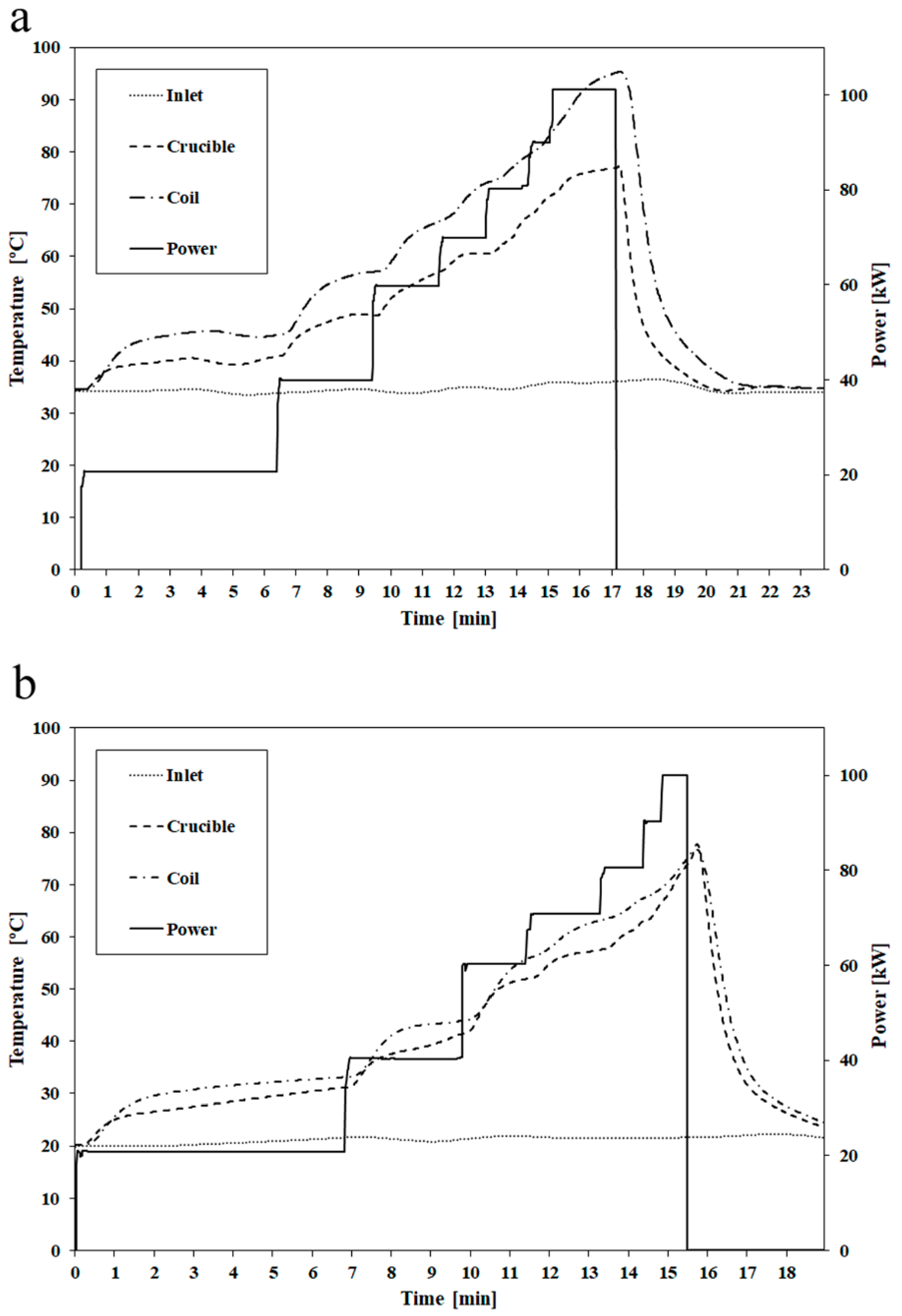
Figure 4.
First melting trial: (a) Real-time power balance. (b) Heat losses in each ISM sub-assembly for each power step.
Figure 4.
First melting trial: (a) Real-time power balance. (b) Heat losses in each ISM sub-assembly for each power step.
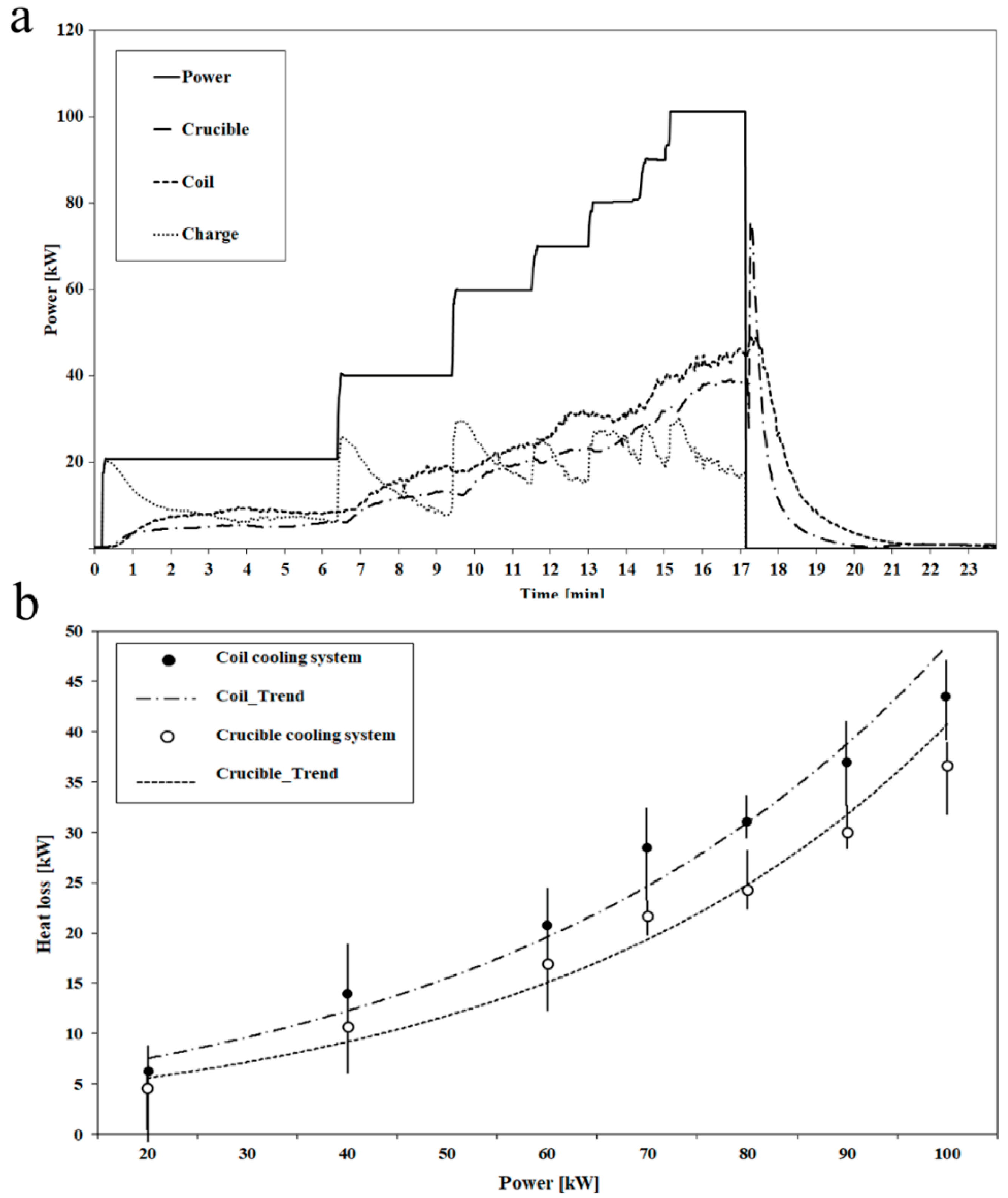
Figure 5.
Second melting trial real-time power distribution.

Figure 6.
Each melting trial real-time thermal efficiency evolution.

Figure 7.
Power profile and charge temperature evolution.


Table 1.
Physical properties of Ti-6Al-4V charge.
| Charge diameter | 60 | [mm] |
| Charge height | 80 | [mm] |
| Charge weight | 1000 | [gr] |
| Tsolidus | 1604 | [°C] |
| Tliquidus | 1660 | [°C] |
| β-transus | 980 | [°C] |
Table 2.
Each melting trial process parameters.
| Parameter | First Melt | Second Melt | Units |
|---|---|---|---|
| Chiller threshold | 33 | 20 | [°C] |
| Crucible water flow | 13 | 10 | [liters·min−1] |
| Coil water flow | 11 | 8 | [liters·min−1] |
| Argon pressure | 100 | 100 | [mbar] |
© 2019 by the authors. Licensee MDPI, Basel, Switzerland. This article is an open access article distributed under the terms and conditions of the Creative Commons Attribution (CC BY) license (http://creativecommons.org/licenses/by/4.0/).
Share and Cite
MDPI and ACS Style
Chamorro, X.; Herrero-Dorca, N.; Bernal, D.; Hurtado, I. Induction Skull Melting of Ti-6Al-4V: Process Control and Efficiency Optimization. Metals 2019, 9, 539. https://doi.org/10.3390/met9050539
AMA Style
Chamorro X, Herrero-Dorca N, Bernal D, Hurtado I. Induction Skull Melting of Ti-6Al-4V: Process Control and Efficiency Optimization. Metals. 2019; 9(5):539. https://doi.org/10.3390/met9050539
Chicago/Turabian StyleChamorro, Xabier, Nuria Herrero-Dorca, Daniel Bernal, and Iñaki Hurtado. 2019. "Induction Skull Melting of Ti-6Al-4V: Process Control and Efficiency Optimization" Metals 9, no. 5: 539. https://doi.org/10.3390/met9050539
Note that from the first issue of 2016, this journal uses article numbers instead of page numbers. See further details here.