Manufacturing of Titanium Components with 3DPMD


Chemnitz University of Technology—Chair of Welding Engineering, Chemnitz D-09126, Germany
*
Author to whom correspondence should be addressed.
Metals 2019, 9(5), 562; https://doi.org/10.3390/met9050562
Submission received: 11 April 2019
/
Revised: 6 May 2019
/
Accepted: 10 May 2019
/
Published: 14 May 2019
(This article belongs to the Special Issue Arc-based Additive Manufacturing)
Abstract
:Within this work, the 3D plasma metal deposition (3DPMD) process is introduced as an additive manufacturing process for titanium components. For this purpose, demonstrators were designed, manufactured and subsequently analyzed. Process-structure-property relationships are discussed. By analyzing the microstructure, the chemical composition and the mechanical-technological properties, it is shown that the production of titanium parts with 3DPMD is possible. The micro tensile tests showed that a load parallel to the build direction is the most critical case for the component. Furthermore, a brittle material behavior could be determined due to enhanced oxygen content in the component. By subsequent heat treatment, the brittle failure behavior could be increased to a fracture elongation of 4.6%. In sum, the 3DPMD process has the potential to manufacture near-net-shape titanium parts out of metal powders. Critical issues are the protection of the weldment and the lack of ductility of the titanium component.
1. Introduction
Driven by the development of high-strength titanium alloys, the demand for large-volume, complex titanium components or prototypes is also increasing [1]. Due to the special properties of titanium, such as extremely poor heat conduction, high strength, tendency to form built-up edges [2], the machining of such components from the solid is only advisable to a limited extent. These disadvantages are reduced by the use of additive manufacturing (AM) technologies. AM enables quick and flexible production of complex, high-strength titanium components in near-net-shape.
The layer by layer production of components from formless material, as opposed to subtractive or formative manufacturing methodologies, is called additive manufacturing [3]. Materials like titanium with an exceptional strength to density ratio and at the same time limited machinability are used particularly frequently in this field. Beam-based powder bed processes, such as selective laser melting (SLM), LaserCUSING® or electron beam melting (EBM) [4,5], currently dominate the market for components of smaller dimensions [1,6,7,8]. These processes are characterized by high final contour proximity and a richness of detail. Disadvantages are the limited construction volume and the low build-up rate per time unit [4,5,6,7,8].
Larger components (m > 10 kg [9]) are manufactured mainly by directed energy deposition processes, such as electron beam additive manufacturing (©Sciaky) and rapid plasma deposition (©norsk titanium) [10,11,12,13]. Further, laser welding [14,15,16], tungsten inert gas welding (shape metal deposition) [15,16] and gas metal arc welding (wire and arc additive manufacturing—WAAM) processes [9,17], using wire as filler material, are widely used. Powder-based freeform processes, like direct metal deposition (DMD), laser engineered net shaping (LENS) or laser metal deposition (LMD) are also part of the current state of the art regarding the additive manufacturing of large titanium components [18,19]. Hybrid processes as a combination of SLM and WAAM also exist. Here the laser process is used to manufacture the base plate and the part is built by WAAM [20].
In the presented work, the advanced freeform and arc-based additive 3D plasma metal deposition (3DPMD) process was used to produce titanium components. 3DPMD is a further development of the classic plasma transferred arc welding process. Low demands on the powder characteristics (particle size, surface structure), high deposition rates () and the possibility of mixing up to four different powders simultaneously during the build-up process are the most significant benefits of this process.
Detailed information on the process, the materials that can be processed and application examples have been published elsewhere [21,22,23].
The aim of the work was to demonstrate the suitability of the novel process 3DPMD for the additive manufacturing of titanium components through the determination of the part properties. For this purpose, the external shape of the produced AM-part was evaluated. Subsequently, metallographic cross-sections were prepared, the microstructures were analyzed, the chemical composition of the components was determined, and micro tensile tests were carried out. Near-net-shape capability, homogeneity, microstructures and tensile tests properties were evaluated.
2. Materials and Methods
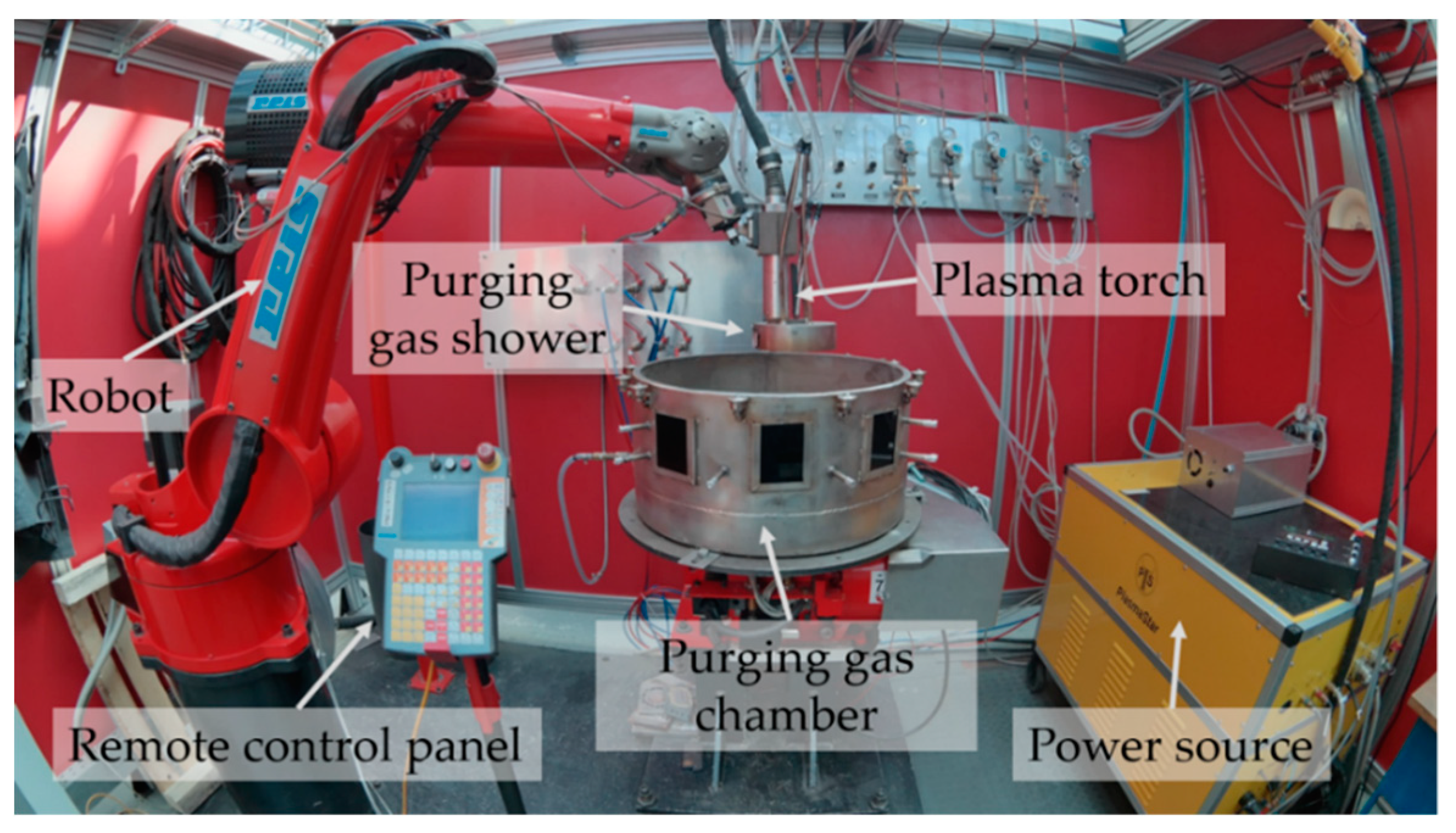
Figure 1 shows the experimental setup of 3DPMD. It consisted of a PLASMASTAR 500 welding source and PLASMASTAR MV230 welding torch. A welding current of IS = 130 A was used. The powdery raw material is fed into the process by a METCO meander disk feeder. Due to the high affinity of titanium to atmospheric gases at temperatures above 300 °C, a purging gas shower in combination with a purging gas chamber was used during the build cycle. The concentric arrangement around the welding torch ensured a homogeneous shielding gas flow. Both protection units—shower and chamber—were vented with argon 6.0 (purity 99.9999 Vol. %) each. High purity argon 6.0 was also used as shielding gas (), carrier gas () and plasma gas (). The distance between the anode and the building platform was set to t = 10 mm. The relative welding speed was vs = 30 cm/min. A six-axis articulated arm robot REIS RV20-16 served as manipulation system.
A hollow cuboid with a side length of l = 90 mm, a height of h = 75 mm and a wall thickness of t = 20 mm was produced as a demonstration object. The layer thickness was z = 1.5 mm. A 10 mm thick Ti6Al4V metal sheet was used as a build platform. For the AM process, pure titanium was used.
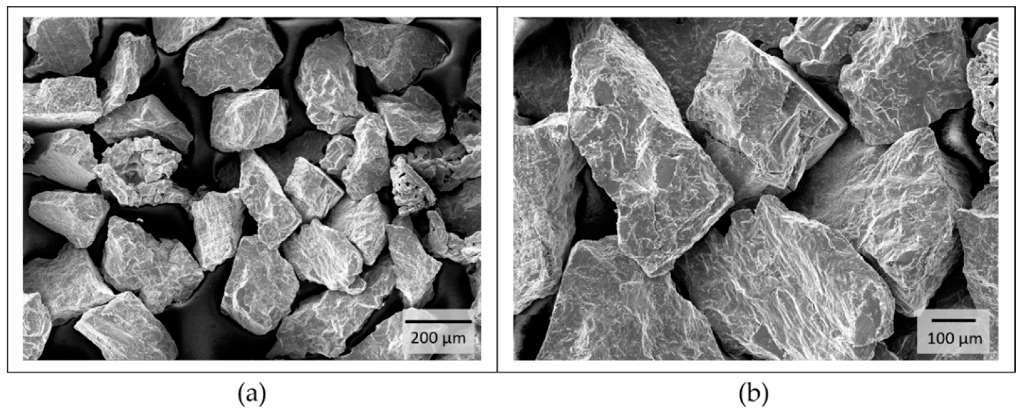
The pure titanium powder used was not standardized and had a particle size of d = 125–335 µm (see Figure 2a). Figure 2b shows the coarse, sharp-edged and blocky structure of the powder. Determination of the powder chemistry was a part of this work.
The morphology of the raw material was examined with a TESCAN MIRA 3 scanning electron microscope (SEM, TESCAN, Dortmund, Germany). The chemical compositions of the powder as well as the final part were determined by X-ray fluorescence spectrometry and inert gas fusion. The microstructure of the component was analyzed by light optical microscopy (Zeiss, Oberkochen, Germany). The extraction of metallographic samples by wet cutting from the components provides the basis for metallographic investigations. The standard metallographic process was used. First, the samples were ground with SiC sandpaper and chemically polished with 1 µm diamond based polishing paste with added hydrofluoric acid. Finally, the polished samples were etched for 10 seconds in a solution of 2 mL hydrofluoric acid (40%) and 98 mL distilled water. The component porosity was determined representatively by optical evaluation and measurement of a metallographic cross-section over the entire component height. The investigation of the mechanical-technological properties was carried out on 21 samples cut by electrical discharge machining and water jet cutting. A forming and quenching dilatometer type DIL 805 A/D from BÄHR was used to carry out the tensile tests and the post-weld heat treatments (PWHT) of the micro specimens. A width of 9 mm, a length of 60 mm and a thickness of 1.5 mm with a web width of 3 mm and a web length of 10 mm determined the dimensions of the micro tensile specimens. The PWHT started with a controlled, linear heating rate of 500 K/h in a vacuum. Subsequently, the test depended heat treatment was carried out. The following cooling was done in an argon atmosphere with a controlled, linear cooling rate of 250 K/h.
3. Results and Discussion
3.1. Build Cycle and External Shape
The total production time of the component was 5 h and 40 min. This results from the proportion of pure processing time with 4 h and 5 min and a set-up time of 1 h and 35 min. The additively manufactured component is shown in Figure 3. After the building process, the component was covered with a thin, non-firmly-attached white oxide layer (see Figure 3a). This oxide layer can be removed completely from the surface by subsequent brushing (see Figure 3b). Process observations have shown that the oxide layer is not formed until the following layer is deposited. The oxide formation on previously deposited layers is caused by heat dissipation induced by the build of layers above. However, the building space itself is very well protected from the atmosphere.
By external view, the component is characterized by a uniform layer structure and a near net shape contour. The achieved surface structure has a high roughness, but no surface pores or cracks are visible. Due to the destined post-processing, the surface roughness is insignificant. The analysis of the process results in a part-specific build-up rate of . Moving towards the process limits, increases in the build-up rate are possible. With reference to the physical density of titanium, a representative component density of ρrel = 99.4% was determined. Compared to the SLM process with ρrel = 99.5% density, the value is just slightly reduced [24].
3.2. Microstructure
The evolution of the microstructure in the component is shown in Figure 4. In comparison to the typical basket-weave α + β structure of the building platform consisting of Ti6Al4V (see Figure 4b), the additively manufactured component is characterized by a structure of alpha laths (see Figure 4c,e). Furthermore, it was found that the width of the alpha laths decreases with increasing component height. The layer-by-layer build process leads to repeated heat input into the previous layers. The associated longer cooling times of the bottom layers lead to increased growth of the lattice structure. In the lower area, the average width of the alpha laths is 11.13 µm (see Figure 4f). In the upper area, an average width of 6.4 µm was determined. This microstructural evolution is very similar to the evolution during a heat treatment, such as annealing or stress relieving [25,26].
3.3. Tensile Tests
The orientation of the micro tensile specimens within the part is sketched in Figure 5a. The results of the micro tensile tests regarding the influence of the loading direction in relation to the build direction are shown in Figure 5b. In total, three tensile tests per position were performed.
It can be seen, that a load perpendicular and inclined 45° to the build direction results in identical ultimate tensile strength values of Rm = 633 MPa. The values determined are higher those that of titanium grade 4 (Rm = 550 MPa) strength. The loading parallel to build direction is the most critical condition, which was tested here. This is in good agreement with the data in the literature [14,27]. The ultimate tensile strength of Rm = 544 MPa corresponds to that of titanium grade 4 [2].
However, it should be noted that all tensile tests carried out in as-welded condition show brittle behavior with an average fracture elongation of A = 0.8%. The lack of ductility and the increased strength values can be explained by an increase in the oxygen level of 0.68 wt.% in the finished AM-part determined by inert gas fusion (Table 1) [2,19]. The uptake of ambient oxygen due to the open chamber characteristic of the welding fixture is probably the main cause of the higher oxygen content. Through the identification of elements in the manufactured part via EDXS measurements further process-related impurities have been excluded, see Figure 6. The display for the element vanadium is below the determination limit and can be neglected.
In order to improve the ductility, individual samples (specimen direction perpendicular to the build direction) were subsequently soft annealed at T1 = 600 °C and T2 = 800 °C for eight hours. The aim was to reduce the strength slightly while simultaneously increasing the ductility without exceeding the beta transus temperature.
The stress-strain curves shown in Figure 7a demonstrate that the intended effect was achieved. With increasing PWHT temperature, lower ultimate tensile strengths and increased fracture elongation values can be observed. With a maximum fracture elongation of A = 4.6% (see Table 2), a low proportion of plastic elongation has been demonstrated. However, this is far below the specification limit of titanium grade 4 (A > 15%). The optical microscopic evaluation of the micro-sections showed no significant changes in the microstructure due to the heat treatment (see Figure 7b). All are characterized by a lattice alpha-structure.
4. Conclusions
Additive manufacturing of titanium components using 3D plasma metal deposition (3DPMD) was shown by a demonstrator geometry. The manufactured part was characterized by a near-net-shape geometry and a flawless surface structure. The observed non-firmly-adhesive oxide layer in combination with the determined increase of the oxygen content in the component is due to insufficient protection of the red-hot part against the atmosphere. By adapting the welding fixture and improving the shielding, these problems should be prevented. The microstructural evaluation showed that with increasing component height the homogeneous alpha lattice structure is reduced. The micro tensile tests carried out showed a significant influence of the loading direction on the achievable strength values. The loading parallel to the building direction is particularly critical. No differences could be found between a perpendicular load and a load inclined 45° to the build direction. The brittle failure characteristics in the as-welded condition were reduced by a subsequent post weld heat treatment.
In summary, 3DPMD is very well suited for the additive manufacturing of titanium components. The production of almost fully dense parts without significant defects shows the great potential of the process.
Author Contributions
Conceptualization, K.H.; methodology, K.H.; validation, K.H and A.N., formal analysis, K.H.; investigation, K.H. and A.N.; writing—original draft preparation, K.H.; writing—review and editing, K.H.; visualization, K.H.; supervision, A.H.; project administration, P.M.
Funding
This research received no external funding.
Conflicts of Interest
The authors declare no conflict of interest.
References
- Wysocki, B.; Maj, P.; Krawcynska, A.; Rozniatowski, K.; Zdunek, J.; Kurzydlowski, K.J.; Swieszkkowski, W. Microstructure and mechanical properties investigation of CP titanium processed by selective laser melting (SLM). J. Mater. Process. Technol. 2017, 241, 13–23. [Google Scholar] [CrossRef]
- Lütjering, G.; Williams, J.C. Titanium, 1st ed.; Springer: Berlin/Heidelberg, Germany, 2003. [Google Scholar]
- ISO/ASTM DIS 52900:2018 Additive Manufacturing–General Principles–Terminology; Beuth: Berlin, Germany, 2018.
- Galarrage, H.; Warren, R.J.; Lados, D.A.; Dehoff, R.R.; Kirka, M.M.; Nandwana, P. Effects of heat treatsments on microstructure and properties of Ti-6Al-4V ELI alloy fabricated by electron beam melting (EBM). Mater. Sci. Eng. 2017, 685, 417–428. [Google Scholar] [CrossRef]
- Nune, K.C.; Li, S.; Misra, R.D.K. Advancements in three-dimensional titanium alloy mesh scaffolds fabricated by electron beam melting for biomedical devices: Mechanical and biological aspects. Sci. Chin. Mater. 2018, 61, 455–474. [Google Scholar] [CrossRef]
- Xu, W.; Brandt, M.; Sun, S.; Elambasseril, J.; Liu, Q.; Latham, K. Additive manufacturing of strong and ductile Ti-6Al-4V by selective laser melting via in situ martensitic decomposition. Acta Mater. 2015, 85, 74–84. [Google Scholar] [CrossRef]
- Vaithilingam, J.; Goodridge, R.D.; Hague, R.J.M.; Christie, S.D.R.; Edmondson, S. The effect of laser melting on the surface chemistry of Ti6al4V components fabricated by selective laser melting. J. Mater. Process. Technol. 2016, 232, 1–8. [Google Scholar] [CrossRef]
- Pyka, G.; Kerckhofs, G.; Papantoniou, I.; Speirs, M.; Schrooten, J.; Wevers, M. Surface roughness and morphology customization of additive manufactured open porous Ti6Al4V structures. Materials 2013, 6, 4737–4757. [Google Scholar] [CrossRef]
- Williams, S.W.; Martina, F.; Addison, A.C.; Ding, J.; Pardal, G.; Colgrove, P. Wire+Arc additive Manufacturing. Mater. Sci. Technol. 2015, 32, 641–647. [Google Scholar] [CrossRef]
- Chen, T.; Pang, S.; Tang, Q.; Suo, H.; Gong, S. Induction of ball-filled pores in electron beam freeform fabrication of Ti-6-Al-4-V alloy by dissolved gas and metallic vapor. Metall. Mater. Trans. A 2015, 46, 5499–5503. [Google Scholar] [CrossRef]
- Martina, F.; Mehnen, J.; Williams, S.W.; Colegrove, P.; Wang, F. Investigation of the benefits of plasma deposition for the additive layer manufacture of Ti-6Al-4V. J. Mater. Process. Technol. 2012, 212, 1377–1386. [Google Scholar] [CrossRef]
- Lin, J.J.; Ly, Y.H.; Liu, Y.X.; Xu, B.S.; Sun, Z.; Li, Z.G.; Wu, Y.X. Microstructural evolution and mechanical properties of Ti-6Al-4V wall deposited by pulsed plasma arc additive manufacturing. Adv. Mater. Res-SWITZ 2016, 102, 30–40. [Google Scholar] [CrossRef]
- Dutta, B.; Froes, F.H. The additive manufacturing (AM) of titanium alloys. Metal. Powder Rep. 2017, 72, 96–106. [Google Scholar] [CrossRef]
- Akerfeldt, P.; Antti, M.-L.; Pederson, R. Influence of microstructure on mechanical properties of laser metal wire-deposition. Mater. Sci. Eng. 2016, 674, 428–437. [Google Scholar] [CrossRef]
- Baufeld, B.; Brandl, E.; Van der Biest, O. Wire based additive layer manufacturing: Comparison of microstructure and mechanical properties of Ti-6Al-4V components fabricated by laser-beam deposition and shape metal deposition. J. Mater. Process. Technol. 2015, 211, 1146–1158. [Google Scholar] [CrossRef]
- Brandl, E.; Baufeld, B.; Leyens, C.; Gault, R. Additive manufactured Ti-6Al-4V using welding wire: Comparison of laser and arc beam deposition and evaluation with respect to aerospace materials specifications. Physcs Proc. 2010, 5, 595–606. [Google Scholar] [CrossRef]
- Wang, J.; Pan, Z.; Ma, Y.; Lu, Y.; Shen, C.; Cuiuri, D.; Li, H. Characterization of wire arc additively manufactured titanium aluminide functionally graded material: Microstructure, mechanical properties and oxidation behavior. Mater. Sci. Eng. 2018, 734, 110–119. [Google Scholar] [CrossRef]
- Carroll, B.E.; Palmer, T.A.; Beese, A.M. Anisotropic tensile behavior of Ti-6Al-4V components fabricated with directed energy deposition additive manufacturing. Acta Mater. 2015, 87, 309–320. [Google Scholar] [CrossRef]
- Beese, A.M.; Carroll, B.E. Review of mechanical properties of Ti-6Al-4V made by laser-based additive manufacturing using powder feedstock. JOM 2016, 68, 724–734. [Google Scholar] [CrossRef]
- Shi, X.; Ma, S.; Liu, C.; Wu, Q.; Lu, J.; Liu, Y.; Shi, W. Selective laser melting-wire arc additive manufacturing hybrid fabrication of Ti-6Al-4V alloy: Microstructure and mechanical properties. Mater. Sci. Eng. 2017, 684, 196–204. [Google Scholar] [CrossRef]
- Hoefer, K.; Hälsig, A.; Mayr, P. Arc-based additive manufacturing of steel components—Comparison of wire- and powder-based variants. Weld World 2018, 62, 243–247. [Google Scholar] [CrossRef]
- Hoefer, K.; Mayr, P. 3DPMD—Additive manufacturing of titanium parts using 3D plasma metal deposition. Mater. Sci. Forum 2018, 941, 2137–2141. [Google Scholar] [CrossRef]
- Hoefer, K.; Nitsche, A.; Abstoss, K.G.; Ertugrul, G.; Haelsig, A.; Mayr, P. Multi-Material additive manufacturing by 3D plasma metal deposition for graded structures of super duplex alloy 1.4410 and the austenitic corrosion resistant alloy 1.4404. JOM 2019, 71, 1554–1559. [Google Scholar] [CrossRef]
- Attar, H.; Ehtemam-Haghighi, S.; Kent, D.; Wu, X.; Dargusch, M.S. Comparative study of commercially pure titanium produced by laser engineered net shaping, selective laser melting and casting process. Mater. Sci. Eng. 2017, 705, 385–393. [Google Scholar] [CrossRef]
- Lütjering, G. Influence of processing on microstructure and mechanical properties (alpha + beta) titanium alloys. Mater. Sci. Eng. 1998, 243, 32–45. [Google Scholar] [CrossRef]
- Dinda, G.; Song, L.; Mazumber, J. Fabrication of Ti-6Al-4V scaffolds by direct metal deposition. Metall. Mater. Trans. A 2008, 38, 2914–2922. [Google Scholar] [CrossRef]
- Yan, M.; Cuiuri, D.; Hoye, N.; Huijun, L.; Zengxi, P. The effect of location on the microstructure and mechanical properties of titanium aluminides produced by additive layer manufacturing using in-situ alloying and gas tungsten arc welding. Mater. Sci. Eng. 2015, 631, 230–240. [Google Scholar] [CrossRef]
Figure 1.
Experimental setup for 3D plasma metal deposition (3DPMD).

Figure 2.
Characterization of the titanium powder morphology. (a) particle size: d = 125–335 µm; (b) the coarse, sharp-edged and blocky structure.
Figure 2.
Characterization of the titanium powder morphology. (a) particle size: d = 125–335 µm; (b) the coarse, sharp-edged and blocky structure.

Figure 3.
Manufactured part (a) as-welded condition (b) brushed condition.

Figure 4.
Overview and optical micrographs of the part at different locations, in: As-welded condition, (a) overview of the AM part, (b) Ti6Al4V build plate, (c) structure of the upper layer, (d) detail structure of the upper layer, (e) structure of the bottom layer, (f) detail structure of the bottom layer.

Figure 5.
Overview of the influence of the loading direction on the tensile strength, condition: As-welded, (a) schematic of the tensile test specimen orientation, (b) results of the tensile tests.
Figure 5.
Overview of the influence of the loading direction on the tensile strength, condition: As-welded, (a) schematic of the tensile test specimen orientation, (b) results of the tensile tests.

Figure 6.
Material spectrum of the base material analyzed with EDX.

Figure 7.
Overview and optical micrographs of the weld metal in different conditions, (a) representative stress-strain-diagrams, (b) representative optical micrographs of the weld metal with mean values of the alpha laths width.
Figure 7.
Overview and optical micrographs of the weld metal in different conditions, (a) representative stress-strain-diagrams, (b) representative optical micrographs of the weld metal with mean values of the alpha laths width.


Table 1.
Oxygen content of the base material analyzed by inert gas fusion.
| Element | Titanium | Oxygen |
|---|---|---|
| Ti Grade 4 | bal. | <0.30 wt.% [2] |
| Raw material | 99.70 wt.% | 0.30 wt.% |
| AM Part | 98.32 wt.% | 0.68 wt.% |
Table 2.
Summary results of the tensile tests (Fmax: maximum strength load, Rp0.2: 0.2% yield strength; Rm: ultimate tensile strength, A: elongation at fracture.
Table 2.
Summary results of the tensile tests (Fmax: maximum strength load, Rp0.2: 0.2% yield strength; Rm: ultimate tensile strength, A: elongation at fracture.
| PWHT | Fmax (N) | Elongation (µm) | Rp0.2 (MPa) | Rm (MPa) | A (%) |
|---|---|---|---|---|---|
| none | 3660 | 80 | 714 | 816 | 0.8 |
| 600 °C/8 h | 3256 | 325 | 805 | 832 | 3.2 |
| 800 °C/8 h | 2762 | 475 | 710 | 732 | 4.6 |
© 2019 by the authors. Licensee MDPI, Basel, Switzerland. This article is an open access article distributed under the terms and conditions of the Creative Commons Attribution (CC BY) license (http://creativecommons.org/licenses/by/4.0/).
Share and Cite
MDPI and ACS Style
Hoefer, K.; Nitsche, A.; Haelsig, A.; Mayr, P. Manufacturing of Titanium Components with 3DPMD. Metals 2019, 9, 562. https://doi.org/10.3390/met9050562
AMA Style
Hoefer K, Nitsche A, Haelsig A, Mayr P. Manufacturing of Titanium Components with 3DPMD. Metals. 2019; 9(5):562. https://doi.org/10.3390/met9050562
Chicago/Turabian StyleHoefer, Kevin, Alexander Nitsche, André Haelsig, and Peter Mayr. 2019. "Manufacturing of Titanium Components with 3DPMD" Metals 9, no. 5: 562. https://doi.org/10.3390/met9050562
Note that from the first issue of 2016, this journal uses article numbers instead of page numbers. See further details here.