Wire and Arc Additive Manufacturing of Aluminum Components


1
Institute for Joining and Welding, Technische Universität Braunschweig, Langer Kamp 6, 38106 Braunschweig, Germany
2
Volkswagen AG, Braunschweig, Gifhorner Straße 180, 38037 Braunschweig, Germany
*
Authors to whom correspondence should be addressed.
Metals 2019, 9(5), 608; https://doi.org/10.3390/met9050608
Submission received: 30 April 2019
/
Revised: 22 May 2019
/
Accepted: 23 May 2019
/
Published: 24 May 2019
(This article belongs to the Special Issue Arc-based Additive Manufacturing)
Abstract
:An increasing demand for flexibility and product integration, combined with reduced product development cycles, leads to continuous development of new manufacturing technologies such as additive manufacturing. Wire and arc additive manufacturing (WAAM) provides promising technology for the near net-shape production of large structures with complex geometry, using cost efficient production resources such as arc welding technology and wire materials. Compared to powder-based additive manufacturing processes, WAAM offers high deposition rates as well as enhanced material utilization. Because of the layer-by-layer built up approach, process conditions such as energy input, arc characteristics, and material composition result in a different processability during the additive manufacturing process. This experimental study aims to describe the effects of the welding process on buildup accuracy and material properties during wire arc additive manufacturing of aluminum structures. Following a process development using pulse cold metal transfer (CMT-P), linear wall samples were manufactured with variations of the filler metal. The samples were analyzed in terms of surface finishing, hardness, and residual stress. Furthermore, mechanical properties were determined in different building directions.
1. Introduction
In recent years, additive manufacturing (AM) processes gained growing interest for customizable fabrication of metal components. In order to meet demands from different industrial sectors, a variety of AM processes with different approaches regarding material deposition have been developed [1]. Thereby, AM processes for manufacturing metal components can mainly be classified into powder-bed, powder-feed, and wire-feed systems [2]. Because of higher deposition rates, wire-based processes are particularly suitable for near net-shape production of large components as well as selective repairs [3,4,5]. Compared to powder-bed processes, another key aspect of wire-based AM processes is the possibility to add geometrically defined material to existing components manufactured by conventional manufacturing processes such as casting or milling. In addition to higher deposition rates, systems technology and wire material for wire and arc additive manufacturing (WAAM) processing are more cost-competitive compared to frequently used direct energy laser deposition technologies (LDTs) [1,3,6]. However, geometrical and surface accuracy are lower compared to powder-based processes. Despite possible postprocessing, additive manufacturing can be economically viable compared to milling from solid material [6,7].
During wire and arc additive manufacturing, part generation is achieved through layer-by-layer deposition of molten metal wire. Thereby, melting of the wire is achieved by arc welding processes. Common process variations are gas metal arc welding (GMAW), gas tungsten arc welding (GTAW), and plasma arc welding (PAW) [8,9,10]. In contrast to GMAW (simultaneous energy input and material feed through consumable wire electrode), wire-feed orientations during GTAW and PAW can affect structure accuracy [11]. Accordingly, GMAW offers advantages in productivity and degree of automation [12]. Based on a low-heat input and precise energy distribution, the cold metal transfer (CMT) process by Fronius currently is the most common GMAW process used for additive manufacturing.
Because of the layer-by-layer built up approach, the WAAM process as well as the resulting structure are directly related to the welding parameters and material characteristics during welding [12]. Accordingly, an increasing number of studies on material processability, tool-path planning, and component properties can be found. However, the majority of current research is focused on steel and titanium [13].
Novel application scenarios consider integration of WAAM for manufacturing of customized aluminum components. Especially in automotive manufacturing, an increasing demand on customization leads to increased variant diversity of individual components. Currently, an individual casting mold is made for each component. In order to reduce investment costs, it is proposed to combine additive manufacturing with high-volume production processes [14]. This involves small adaptions to modify kinematic points or higher loads as well as partial additive manufacturing, which adds on basic workpieces made from a large-volume production. Thereby, mechanical properties of the added structures should be comparable to the basic workpiece to maintain lightweight design potentials. To meet the requirements of geometrical accuracy and structural properties, research and development for WAAM processing of aluminum is needed.
Regarding the application scenario as well as the general demands for material composition and properties, wire and arc additive manufacturing of Al-4047 and Al-5356 wire has been studied in terms of processability, buildup structure, and resulting material properties.
2. Materials and Methods
Experiments were carried out on Al-6082 substrates with dimensions 150 mm × 40 mm × 10 mm. Al-6082 was chosen as a typical representative of aluminum wrought alloys with high weldability and thermal conductivity. The substrate only affected the first layer, whereby this work was focused on the AM component and did not include the interface layer. Prior to welding, the substrate surface was cleaned using acetone in order to remove any organic contaminants. For deposition, a solid wire electrode with a diameter of 1.0 mm was used. The chemical compositions of the materials are shown in Table 1.
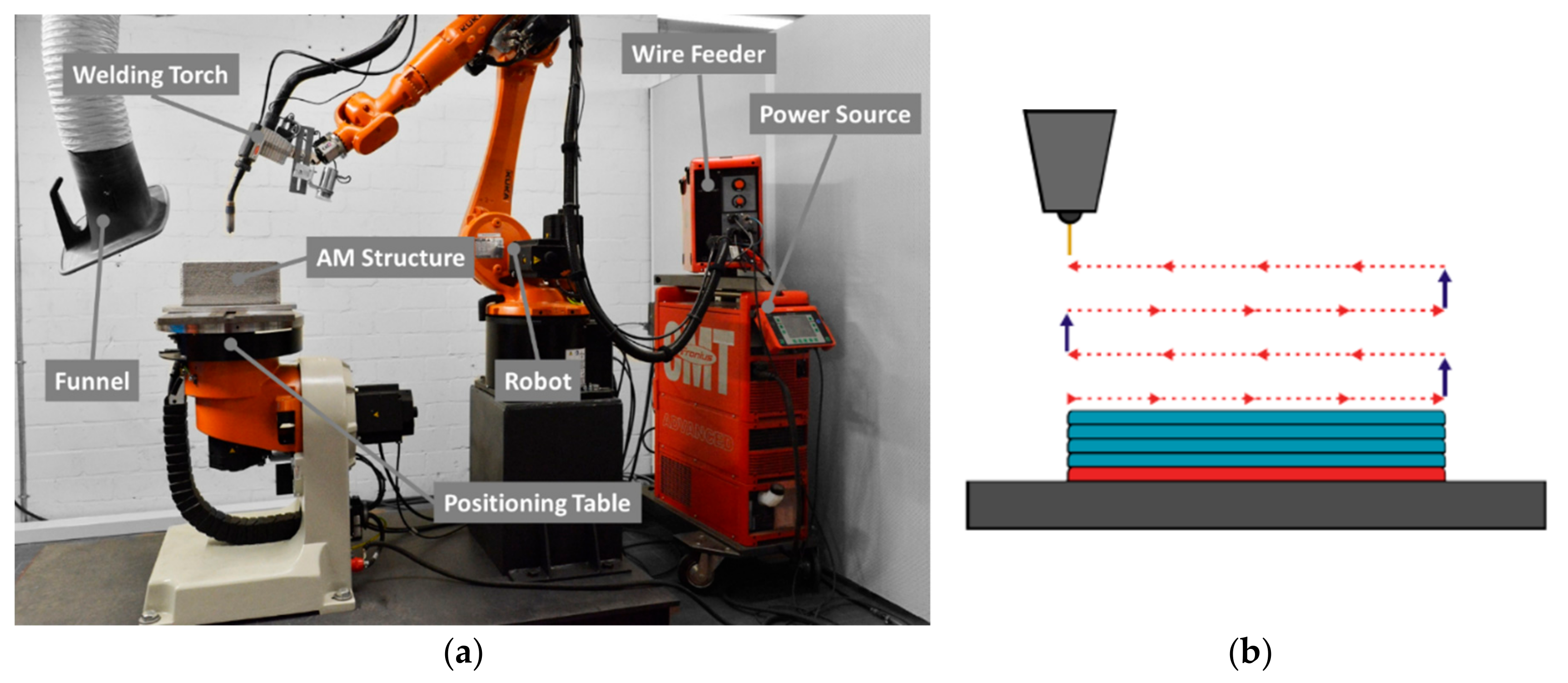
A Fronius CMT Advanced 4000 R welding power source combined with a KUKA KR22 robotic handling system (KUKA Deutschland GmbH, Augsburg, Germany) was used for the WAAM process, as shown in Figure 1. Fundamental studies on process behaviors have been conducted on thin-walled specimens with 20 single pass layers at a length of 100 mm. For the extraction of tensile test samples, specimens with 100 single pass layers at a length of 300 mm were used. The schematic process sequence for thin-walled sample preparation is given in Figure 1.
Because of a low heat input of the conventional CMT process, insufficient root penetration could be detected in preliminary studies, whereas CMT-Pulse was found to be more suitable for processing examined materials. Accordingly, the samples were prepared using the CMT-Pulse mode with material-specific current characteristics. Table 2 provides the underlying parameters as well as the welding speed, wire feed, and the offset per layer in building directions. For both wire materials, the preheating and interpass temperature on the top layer was 100 °C. In order to obtain a constant interpass temperature, the intermediate time between single layers was adjusted with the structure height using type-K thermocouples for temperature measurements. The contact tip to workpiece distance was fixed at 10 mm. Argon (Ar ≥ 99.996%) was used as shielding gas using a constant flow of 14 l/min.
After visual examination, linear walls were first measured regarding the resulting height and width. In addition, profile measurement using a laser scanner (micro-optronic, Langebrück, Germany) was conducted in the building direction of the thin-walled surface. To determine waviness of the wall surface, deviations from the profile centerline were averaged over 15 profile measurements along the wall length. Metallographic samples were taken from the middle part of the samples for macrostructure analysis. The samples were polished and etched with 2% hydrofluoric acid. Hardness measurements were conducted at different layers of the buildup structure using hardness testing according to Vickers (ITW Test & Measurement GmbH, Esslingen am Neckar, Germany) with a test force of 9.8 N. In order to obtain an in-depth understanding of the process, highspeed videography at 5000 fps was integrated in the experimental setup to capture the droplet transition and melt pool geometry.
Residual stress was analyzed by means of X-ray diffraction in two thin-walled specimens each made from 20 layers of either Al-4047 and Al-5356. The interpass temperature while welding was 100 °C in both samples. Stresses were determined from diffraction patterns by means of the sin2Ψ method using the (hkl) crystalline plane {331} of aluminum [15]. Eight Ψ-angles were used between 144° and 154°. The radiation source was cobalt, and the elastic constant 0.5S2 = 18.93 mm2/N. In order to establish a homogeneous surface for measurement, electrolytic polishing was performed before testing (~50 µm removed). However, standard deviations of the sin2Ψ fit (due to coarse grains in the weld metal) were quite large compared to typical measurements in as-wrought base metal.
Samples for tensile testing were sectioned from the additively manufactured thin-walled structures, as depicted in Figure 2, and prepared according to EN ISO 6892-1 standards. The start and end sections of the welding process were cut off and discarded. Tensile test was conducted at room temperature with a test speed of 3.2 mm/min.
3. Results and Discussion
3.1. Comparison of Additively Manufactured Al-4047 and Al-5356
The resulting wall structures using Al-4047 and Al-5356 are shown in Figure 3. The results from visual examination indicated a more uneven geometry formation with higher waviness using Al-4047 (Figure 3a). The samples using Al-5356 showed a smooth and uniform wall surface (Figure 3b). Geometric data were determined at multiple points along the depositing direction not including the start and end sections. For Al-4047, the width of the structure ranged from 9.6 to 12.1 mm at a height of 22.3 to 24.8 mm. A narrower and higher structure with less deviation along the depositing direction could be determined using Al-5356 with a width ranging from 8.3 to 9.2 mm and a height of 26.6 to 27.9 mm.
As buildup during the WAAM process is layer based and highly depends on the weld behavior of the applied materials, highspeed imaging of the weld zone was used for further understanding the impact of the welding process on geometry formation. Figure 4 compares the welding processes for the examined materials based on pictures taken during droplet transitions. From the pictures, fundamental differences regarding the molten weld pool can be detected. The length of the molten pool showed a nominal value of approximately 16 mm using Al-4047, whereas the length of the molten pool during welding of Al-5356 was approximately 10 mm. This may be explained by the solidification range of the studied alloys. Al-4047 stated a near-eutectic alloy with a narrow solidification range from 585 to 573 °C [16]. By comparison, the solidification range of Al-5356 ranged from 635 to 565 °C [16]. This led to the conclusion that solidification of Al-5356 started at much higher temperatures, which resulted in a smaller molten pool supported by surrounding material in a semisolid state. As a result of the smaller molten pool, the weld pool dynamic during the droplet transition was found to be steadier, which led to a smooth and uniform buildup of material.
A further explanation for the difference in molten pool size is given by higher heat input during welding of Al-4047 (cf. Table 2). Further experiments with reduced energy input (current/voltage) as well as reduced interpass temperature could not indicate an improvement of geometric accuracy of the finished wall structure.
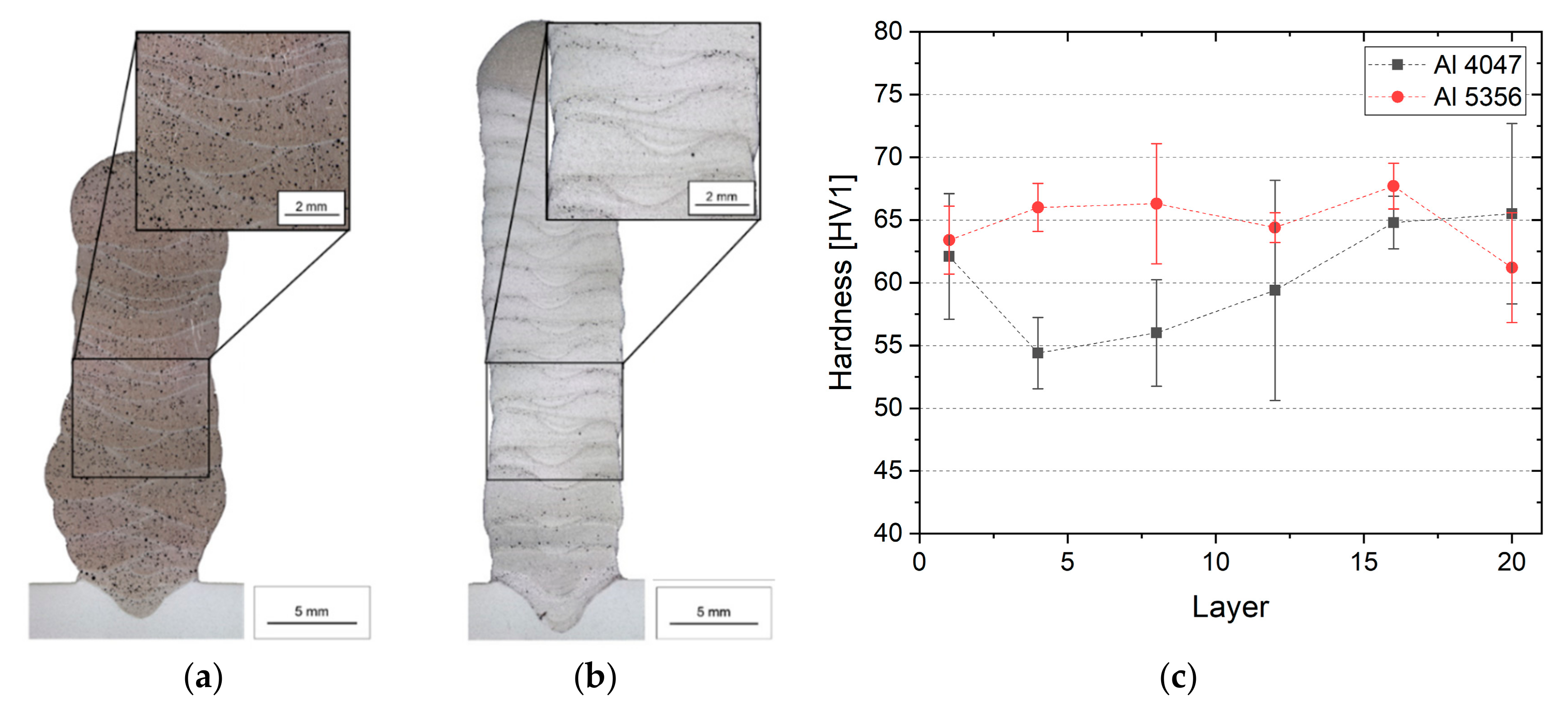
Figure 5 illustrates material accumulation by the WAAM process. Based on the micrographs, an uneven lateral shift of the layers using Al-4047 was detected. On the other hand, buildup using Al-5356 showed a defined structure of the layers. Considering previous results, this may be explained by the different solidification ranges of the materials. Furthermore, an evenly dispersed fine porosity (less than 50 µm in diameter) can be detected for both materials with a significantly higher number of single pores for Al-4047.
In order to determine the impact of multipass welding on the mechanical properties of the underlying structure, a hardness test was conducted along the building direction. As shown in Figure 5c, no significant change in hardness values can be detected along the buildup of Al-5356. This indicated that the thermal history of the structure during additive manufacturing had only minor impact on the hardness of the overall structure. Hardness values of Al-4047 showed an inhomogeneous profile with a slight decrease in the bottom half of the buildup structure followed by an increase towards the top layers. As Al-4047 can be subjected to heat treatment in special cases, it was assumed that energy input during welding led to lower hardness in lower parts of the structure and should be subject to investigation in further studies.
3.2. Effects of Process Adjustments
For further process evaluation, the effects of arc length correction and pulse correction on buildup quality of WAAM wall structures were examined on a thin-walled specimen with 10 single pass layers using Al-5356. Arc length correction affected the pulsed voltage for the pulse phase and the reverse movement in the CMT phase; this led to an increased arc length for positive corrections and vice versa. The pulse/arc-force correction led to a change of pulse energy and pulse frequency in the pulse phase. Positive corrections stated an increase of pulse energy as well as a reduction in pulse frequency and vice versa.
As depicted in Figure 6, highspeed imaging and metallographic cross sections were used to observe an unsteady welding process caused by irregular extinction of the arc applying negative correction values. Furthermore, positive correction values led to an uneven droplet transition caused by an increased arc energy and length. Additionally, measurements of surface waviness indicated an increased waviness of the resulting wall structure while applying arc and/or pulse correction. Results indicated that an even droplet transition was a decisive factor for obtaining a smooth and uniform surface of the WAAM buildup. In this case, an even droplet transition was determined using neutral correction values (i.e., neutral current characteristics provided by power source manufacturer).
3.3. Mechanical Properties and Residual Stress
Because poor wall geometry was observed using Al-4047 during WAAM deposition, mechanical properties of the WAAM structure were only determined for Al-5356 using neutral settings for arc and pulse correction (Figure 6b). The resulting tensile properties are given in Figure 7. In the horizontal direction, ultimate tensile strength ranged from 262 to 273 MPa at an elongation of 26% to 31%. In the vertical direction, tensile strength ranged from 247 to 260 Mpa. Elongation was found to be approximately 40% lower in the vertical direction with values ranging from 14% to 20%. The mean values as well as the properties of the filler metal are summarized in Table 3. Compared to the provided material properties of the wire material, it was found that samples in the horizontal direction met the requirements; however, elongation in the vertical stress direction was found to be lower compared to material specifications. A possible explanation for this was the occurrence of porosity as well as an inhomogeneous microstructure along the fusion zone of single layers; this should be scope of further research. In both cases, no significant dependencies on sample allocation in the deposited wall were observed. From this data, it can be stated that uniform material properties across the deposited wall can be expected.
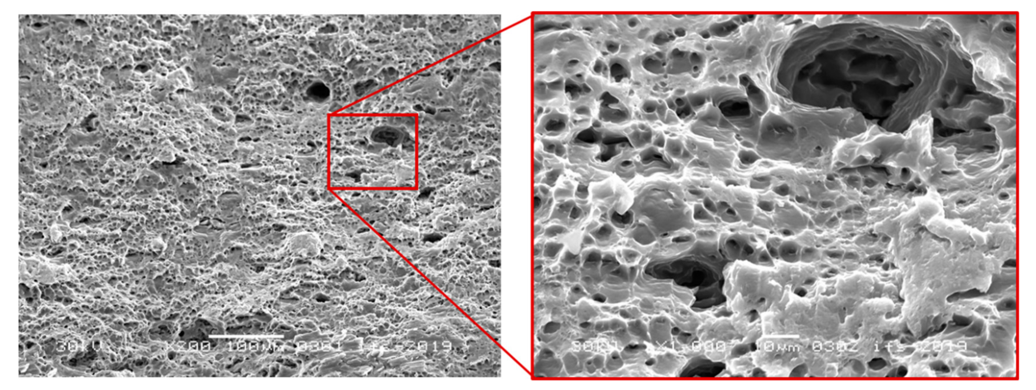
Fracture surfaces were similar for the horizontal and vertical directions with no distinctive differences to be found. Furthermore, failure was evenly distributed along the buildup direction with no specific pattern to be observed, which underlined uniform material properties. Figure 8 presents scanning electron microscope images of the fracture surface morphology in the horizontal direction. The fracture surface was mainly characterized by dimples, which indicated a ductile fracture. Further, micropores could be detected embedded in the fracture surface morphology.
Residual stress was measured on top of the last layer as well as the top side of the base plate in both longitudinal (welding) and transverse directions. The residual stress magnitudes ranged from +40 ± 10 to −85 ± 21 MPa in the longitudinal direction and from −66 ± 34 to −95 ± 15 MPa on top of the last layer of the Al-4047 specimen. A higher and more homogenous compressive residual stress was determined in the top layer of Al-5356 ranging from −150 ± 60 to −156 ± 44 MPa. The top surfaces of the base plates were also in compression with values of approximately −50 MPa.
Overall, residual stress magnitudes depended on the yield limit of the filler metals used. The softer Al-4047 showed less residual stress than Al-5356. The overall distribution of residual stress (compression on top of the last layer and the base plate) corresponded to reported results from the literature [17]. For equilibrium reasons, the first layers of the walls as well as the bottom surface of the base plate were in tension.
Further studies on the residual stress shall study the influence of the interpass temperature as well as the energy input while welding.
4. Conclusions
Process characteristics, mechanical properties, and residual stress of wire and arc additive manufacturing using Al-4046 and Al-5356 have been investigated within the underlying study. Linear walls were built and analyzed with the following conclusions:
- The accuracy and deposition properties during WAAM depend on the material’s characteristics. The solidification range and setting behavior have significant effects on surface waviness. The results of this study indicate that a wide solidification range is more suitable for uniform deposition.
- Another controlling factor for the resulting surface waviness is an even droplet transition of the welding process. Increased arc length and pulse energy result in higher dynamic forces during droplet transition, thus affecting deposition accuracy.
- Mechanical properties depend on the direction of loading. Samples taken vertical to the buildup direction resulted in significant loss of elongation. In the horizontal direction material properties meet the material requirements.
- Material properties are evenly distributed over the buildup geometry when the interpass temperature is kept constant.
- Residual stress magnitude depends on yield strength of the filler material. The first layer of the thin-walled structure as well as the bottom surface of the substrate are in tension, whereas the top layer and substrate surface undergo compression.
Author Contributions
Conceptualization, M.K. and J.H.; methodology, M.K. and J.H.; formal analysis, M.K. and J.H.; investigation, M.K.; resources, S.F. and K.D.; data curation, J.H.; writing—original draft preparation, M.K., S.F., and J.H.; writing—review and editing, J.H.; visualization, M.K.; supervision, K.D.; project administration, J.H.; funding acquisition, K.D.
Funding
This research received no external funding.
Acknowledgments
We acknowledge support by the German Research Foundation and the Open Access Publication Funds of the Technische Universität Braunschweig.
Conflicts of Interest
The authors declare no conflict of interest.
References
- Ding, D.; Pan, Z.; Cuiuri, D.; Li, H. Wire-feed additive manufacturing of metal components: Technologies, developments and future interests. Int. J. Adv. Manuf. Technol. 2015, 81, 465–481. [Google Scholar] [CrossRef]
- Frazier, W.E. Metal Additive Manufacturing: A Review. J. Mater. Eng. Perform. 2014, 23, 1917–1928. [Google Scholar] [CrossRef]
- Taminger, K.M.; Hafley, R.A. Electron Beam Freeform Fabrication for Cost Effective Near-Net Shape Manufacturing. In Proceedings of the NATO/RTO AVT-139 Specialists’ Meeting on Cost Effective Manufacture via Net Shape Processing, Amsterdam, The Netherlands, 15–17 May 2006. [Google Scholar]
- Fischer, G.; Röhrich, T. Lichtbogenbasierte additive Fertigung: Anwendungen für die Luftfahrtindustrie. In Proceedings of the DVS CONGRESS, Friedrichshafen, Germany, 16–17 September 2018. [Google Scholar]
- Thomas-Seale, L.E.J.; Kirkman-Brown, J.C.; Attallah, M.M.; Espino, D.M.; Shepherd, D.E.T. The barriers to the progression of additive manufacture: Perspectives from UK industry. Int. J. Prod. Econ. 2018, 198, 104–118. [Google Scholar] [CrossRef]
- Baufeld, B.; Widdison, R.; Dutilleul, T.; Bridger, K. Electron Beam Additive Manufacturing at the Nuclear AMRC. Elektronika ir Elektrotechnika 2016, 51, 25–30. [Google Scholar]
- Bekker, A.C.M.; Verlinden, J.C. Life cycle assessment of wire + arc additive manufacturing compared to green sand casting and CNC milling in stainless steel. J. Clean. Prod. 2018, 177, 438–447. [Google Scholar] [CrossRef]
- Liberini, M.; Astarita, A.; Campatelli, G.; Scippa, A.; Montevecchi, F.; Venturini, G.; Durante, M.; Boccarusso, L.; Minutolo, F.M.C.; Squillace, A. Selection of Optimal Process Parameters for Wire Arc Additive Manufacturing. Procedia CIRP 2017, 62, 470–474. [Google Scholar] [CrossRef]
- Hoefer, K.; Haelsig, A.; Mayr, P. Arc-based additive manufacturing of steel components—Comparison of wire- and powder-based variants. Weld. World 2018, 62, 243–247. [Google Scholar] [CrossRef]
- Reisgen, U.; Sharma, R.; Oster, L.; Zanders, E. Plasma-Mehrdraht-Schweißen zum Herstellen gradierter Strukturen. In Proceedings of the DVS CONGRESS, Friedrichshafen, Germany, 16–17 September 2018; pp. 109–114. (In German). [Google Scholar]
- Wu, Q.; Lu, J.; Liu, C.; Shi, X.; Ma, Q.; Tang, S.; Fan, H.; Ma, S. Obtaining uniform deposition with variable wire feeding direction during wire-feed additive manufacturing. Mater. Manuf. Processes 2017, 32, 1881–1886. [Google Scholar] [CrossRef]
- Fang, X.; Zhang, L.; Li, H.; Li, C.; Huang, K.; Lu, B. Microstructure Evolution and Mechanical Behavior of 2219 Aluminum Alloys Additively Fabricated by the Cold Metal Transfer Process. Materials 2018, 11, 812. [Google Scholar] [CrossRef] [PubMed]
- Gu, J.; Cong, B.; Ding, J.; Williams, S.W.; Zhai, Y. Wire + Arc Additive Manufacturing of Aluminium. In Proceedings of the 25th Annual International Solid Freeform Fabrication Symposium, Austin, TX, USA, 4–6 August 2014; pp. 451–458. [Google Scholar]
- Dröder, K.; Heyn, J.K.; Gerbers, R.; Wonnenberg, B.; Dietrich, F. Partial Additive Manufacturing: Experiments and Prospects with Regard to Large Series Production. Procedia CIRP 2016, 55, 122–127. [Google Scholar] [CrossRef] [Green Version]
- Genzel, C.; Denks, I.; Klaus, M. (Eds.) Modern Diffraction Methods: Residual Stress Analysis by X-ray Diffraction Methods; Wiley: Hoboken, NJ, USA, 2013. [Google Scholar]
- Okamoto, H.; Schlesinger, M.E.; Mueller, E.M. (Eds.) ASM Handbook Volume 3: Alloy Phase Diagrams; ASM International: Geauga County, OH, USA, 1998. [Google Scholar]
- Colegrove, P.A.; Coules, H.E.; Fairman, J.; Martina, F.; Kashoob, T.; Mamash, H.; Cozzolino, L.D. Microstructure and residual stress improvement in wire and arc additively manufactured parts through high-pressure rolling. J. Mater. Process. Technol. 2013, 213, 1782–1791. [Google Scholar] [CrossRef]
Figure 1.
Experimental setup for robot-guided wire and arc additive manufacturing (WAAM) (a) and a schematic process sequence for sample manufacturing (b).
Figure 1.
Experimental setup for robot-guided wire and arc additive manufacturing (WAAM) (a) and a schematic process sequence for sample manufacturing (b).

Figure 2.
Dimensions of tensile sample in mm, Rz in µm (a) and schematic representation of sample extraction (b).
Figure 2.
Dimensions of tensile sample in mm, Rz in µm (a) and schematic representation of sample extraction (b).

Figure 3.
Manufactured samples: (a) Al-4047 and (b) Al-5356.

Figure 4.
Highspeed images during buildup of Al-4047 (a) and Al-5356 (b).

Figure 5.
Cross-section micrographs of WAAM samples (a) Al-4047, (b) Al-5356, and (c) hardness distribution depending on buildup height.
Figure 5.
Cross-section micrographs of WAAM samples (a) Al-4047, (b) Al-5356, and (c) hardness distribution depending on buildup height.

Figure 6.
Effect of process adjustments on droplet transition and waviness of the structure: (a) negative arc and pulse corrections, (b) neutral settings, and (c) positive arc and pulse corrections.
Figure 6.
Effect of process adjustments on droplet transition and waviness of the structure: (a) negative arc and pulse corrections, (b) neutral settings, and (c) positive arc and pulse corrections.

Figure 7.
Tensile properties of processed Al-5356 in (a) horizontal and (b) vertical directions.

Figure 8.
Scanning electron microscope microstructure of the fracture sample after the tensile test.
Figure 8.
Scanning electron microscope microstructure of the fracture sample after the tensile test.


Table 1.
Nominal composition of welding wires.
| Material | Alloy | Chemical Composition (wt %) | |||||
|---|---|---|---|---|---|---|---|
| Al | Mn | Mg | Si | Fe | Cu | ||
| Wire | Al-4047 | bal | 0.2 | - | 12.0 | - | - |
| Al-5356 | bal | 0.15 | 5.0 | 0.05 | 0.15 | - | |
| Substrate | Al-6082 | bal | 0.4–1.0 | 0.60–1.2 | 0.7–1.3 | <0.5 | <0.1 |
Table 2.
Welding parameters used for sample processing.
| Parameter | Unit | Al 4047 | Al 5356 |
|---|---|---|---|
| Wire feed | m/min | 8 | 8 |
| Welding speed | cm/min | 60 | 60 |
| Voltage | V | 19–20 | 15–15.5 |
| Current | A | 125–127 | 91–92 |
| Layer thickness | mm | 1.2 | 1.4 |
| Nominal wall height | mm | 24 | 28 |
Table 3.
Mechanical properties determined from additive manufacturing (AM)-processed Al-5356.
| Properties | Unit | Wire Specification | WAAM (H) | WAAM (V) |
|---|---|---|---|---|
| Yield strength | MPa | 125 | 114.9 ± 1.0 | 114.9 ± 2.7 |
| Ultimate tensile strength | Mpa | 255 | 267.6 ± 3.5 | 254.0 ± 5.6 |
| Elongation | % | 24 | 28.3 ± 2.1 | 17.1 ± 2.7 |
(H—horizontal; V—vertical).
© 2019 by the authors. Licensee MDPI, Basel, Switzerland. This article is an open access article distributed under the terms and conditions of the Creative Commons Attribution (CC BY) license (http://creativecommons.org/licenses/by/4.0/).
Share and Cite
MDPI and ACS Style
Köhler, M.; Fiebig, S.; Hensel, J.; Dilger, K. Wire and Arc Additive Manufacturing of Aluminum Components. Metals 2019, 9, 608. https://doi.org/10.3390/met9050608
AMA Style
Köhler M, Fiebig S, Hensel J, Dilger K. Wire and Arc Additive Manufacturing of Aluminum Components. Metals. 2019; 9(5):608. https://doi.org/10.3390/met9050608
Chicago/Turabian StyleKöhler, Markus, Sierk Fiebig, Jonas Hensel, and Klaus Dilger. 2019. "Wire and Arc Additive Manufacturing of Aluminum Components" Metals 9, no. 5: 608. https://doi.org/10.3390/met9050608
Note that from the first issue of 2016, this journal uses article numbers instead of page numbers. See further details here.