Charpy Impact Properties of Hydrogen-Exposed 316L Stainless Steel at Ambient and Cryogenic Temperatures
by
 , ,
, ,
Le Thanh Hung Nguyen
 ,
,
Jae-Sik Hwang
,
Myung-Sung Kim
,
Jeong-Hyeon Kim
,
Seul-Kee Kim
and
Jae-Myung Lee
* Department of Naval Architecture and Ocean Engineering, Pusan National University, 30, Jangjeon-Dong, Geumjeong-Gu, Busan 609-735, Korea
*
Author to whom correspondence should be addressed.
Metals 2019, 9(6), 625; https://doi.org/10.3390/met9060625
Submission received: 14 May 2019
/
Revised: 26 May 2019
/
Accepted: 27 May 2019
/
Published: 29 May 2019
(This article belongs to the Special Issue Hydrogen Embrittlement of Metallic Materials: Past, Present and Future)
Abstract
:316L stainless steel is a promising material candidate for a hydrogen containment system. However, when in contact with hydrogen, the material could be degraded by hydrogen embrittlement (HE). Moreover, the mechanism and the effect of HE on 316L stainless steel have not been clearly studied. This study investigated the effect of hydrogen exposure on the impact toughness of 316L stainless steel to understand the relation between hydrogen charging time and fracture toughness at ambient and cryogenic temperatures. In this study, 316L stainless steel specimens were exposed to hydrogen in different durations. Charpy V-notch (CVN) impact tests were conducted at ambient and low temperatures to study the effect of HE on the impact properties and fracture toughness of 316L stainless steel under the tested temperatures. Hydrogen analysis and scanning electron microscopy (SEM) were conducted to find the effect of charging time on the hydrogen concentration and surface morphology, respectively. The result indicated that exposure to hydrogen decreased the absorbed energy and ductility of 316L stainless steel at all tested temperatures but not much difference was found among the pre-charging times. Another academic insight is that low temperatures diminished the absorbed energy by lowering the ductility of 316L stainless steel.
1. Introduction
The Marine Environment Protection Committee (MEPC) of the International Maritime Organization (IMO) regulations met for its 72nd session with the aim to dramatically reduce the greenhouse gas emissions from ships by at least 50% by 2050 compared to 2008 [1]. The new regulations lead to the high demand for new eco-friendly fuels for marine ships and vessels with low greenhouse gas emissions. Among the alternative energies, liquid hydrogen (LH2) has been of great concern because it has zero carbon dioxide emissions in the exhaust gas and a higher energy-to-weight ratio in comparison with conventional fuels, like natural gas or gasoline. Despite these advantages, hydrogen can dissolve into materials and cause hydrogen embrittlement (HE) in hydrogen containers because of its small size [2]. Furthermore, a low temperature of up to −253 °C of liquid hydrogen could make the materials used for LH2 vessels become brittle. Therefore, the effect of cryogenic temperature and HE on the working capability of materials used for hydrogen containers must be understood. Figure 1 illustrates a hydrogen container.
For the transportation and storage of LH2, 316L stainless steel is considered one of the most attractive material candidates for liquid hydrogen-containing vessels because of its high resistance to HE [3] and good mechanical properties at low temperatures [4]. Understanding the effect of cryogenic temperature and HE on the performance of 316L stainless steel is very important in selecting 316L stainless steel as a material candidate for containing liquid hydrogen. However, the mechanism of HE on 316L stainless steel has not yet been clearly understood [5].
Former studies investigated the influence of HE on the mechanical properties and microstructure of 316L stainless steel. Fukuyama et al. (2004) conducted tensile tests at 10–70 MPa of hydrogen atmosphere and at ambient temperature for 316L stainless steel. They realized that the impact of hydrogen on the tensile performance of the material was negligible. Hydrogen was only distributed in the thin outer layer and its concentration was not uniform along with the specimen because of its low diffusivity [6]. Kanezaki et al. (2008) cathodically charged 316L stainless steel in a H2SO4 solution (pH = 3.5) at 27 A/m2, 50 °C for 672 h. They found that hydrogen was only distributed in the thin outer layer with a thickness of approximately 100–200 μm after cathodic charging and the high hydrogen concentration was only distributed on the 100 μm outer layer [7]. The high nickel content of 316L stainless steel promotes a better stability of the austenite phase, which plays an important role in resistance against hydrogen-assisted fracture [8]. In the cubic lattice of materials, the presence of hydrogen in the matrix causes several changes, such as defects in transformation and phase formation. For austenitic stainless steels like 316L stainless steel, HE leads to the phase transformation from austenitic γ (face-centered cubic) to ε (hexagonal close-packed) and α (body-centered cubic) as proven by several studies [9,10,11]. The diffusion rate of hydrogen in the γ-austenite phase is lower than that in the martensite phase; therefore, the effect of HE in the former phase is lower. Furthermore, HE also changes the surface morphology and microstructure of hydrogen-exposed specimens [12].
Although some studies have reported the effect of HE on the performance of 316L stainless steel in the cryogenic environment, they are different from those reported by this study. Former tensile tests were conducted to study the effect of HE on the mechanical properties of materials in the ambient and cryogenic temperatures [13,14,15,16]. However, fracture toughness is also an important parameter in evaluating the resistance of a pre-cracked material under an applied load. The Charpy V-notch (CVN) impact test [17] is utilized to estimate the absorbed energy during fracture under a high strain rate. This test is widely applied in the industry to measure the material’s fracture toughness because of its low cost, simplicity and popularity [18]. Former studies concluded that hydrogen exposure decreased the impact toughness of steels [19,20]; however, others found that the effect of hydrogen exposure on the impact toughness of steels was negligible [5,21]. Nevertheless, the effect of HE on the impact behavior of steels at the cryogenic temperature was not clearly investigated. Thus, the cryogenic impact performance of 316L stainless steel and the effect of HE on this material must be understood to select 316L stainless steel as a candidate for hydrogen-containing vessels.
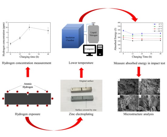
This study revealed the effect of hydrogen exposure on the fracture toughness of 316L stainless steel, including the impact resistance of 316L stainless steel under low temperature. Various durations of cathodic hydrogen charging were used to cause HE in the 316L stainless steel specimens. After charging, zinc electroplating was performed to prevent hydrogen from being desorbed out of the specimens and maintain HE. The CVN impact test at the ambient and low temperatures was conducted to determine the fracture toughness and the ductility of the specimens after being degraded by HE. Meanwhile, the hydrogen amount in each case was measured to study the relationship between the hydrogen concentration and the absorbed energy of the specimens. The microstructure of the fracture surfaces was investigated by a scanning electron microscope to understand the characteristic of the fracture and ascertain the CVN impact test result.
2. Materials and Methods
2.1. Material
The 316L stainless steel exhibited high resistance to HE, showing excellent mechanical performance at low temperatures. This study used 316L stainless steel made based on the Japanese standard. Table 1 shows the composition of 316L stainless steel.
2.2. Specimens
The specimens were made based on ASTM E23—16b: Standard Test Methods for Notched Bar Impact Testing of Metallic Materials [17]. V-notched specimens are widely used to test the absorbed energy of metals because they are easy to prepare and the CVN impact test results can be achieved quickly and cheaply. Each specimen had a specific dimension of 55 mm × 10 mm × 10 mm in length, width and thickness, respectively. The V-notch was 2 mm in depth and 45 degree in V-angle. The notch radius was 0.25 mm. Figure 2 illustrates the dimension of each V-notched specimen.
2.3. Cathodic Hydrogen Charging and Zn Electroplating
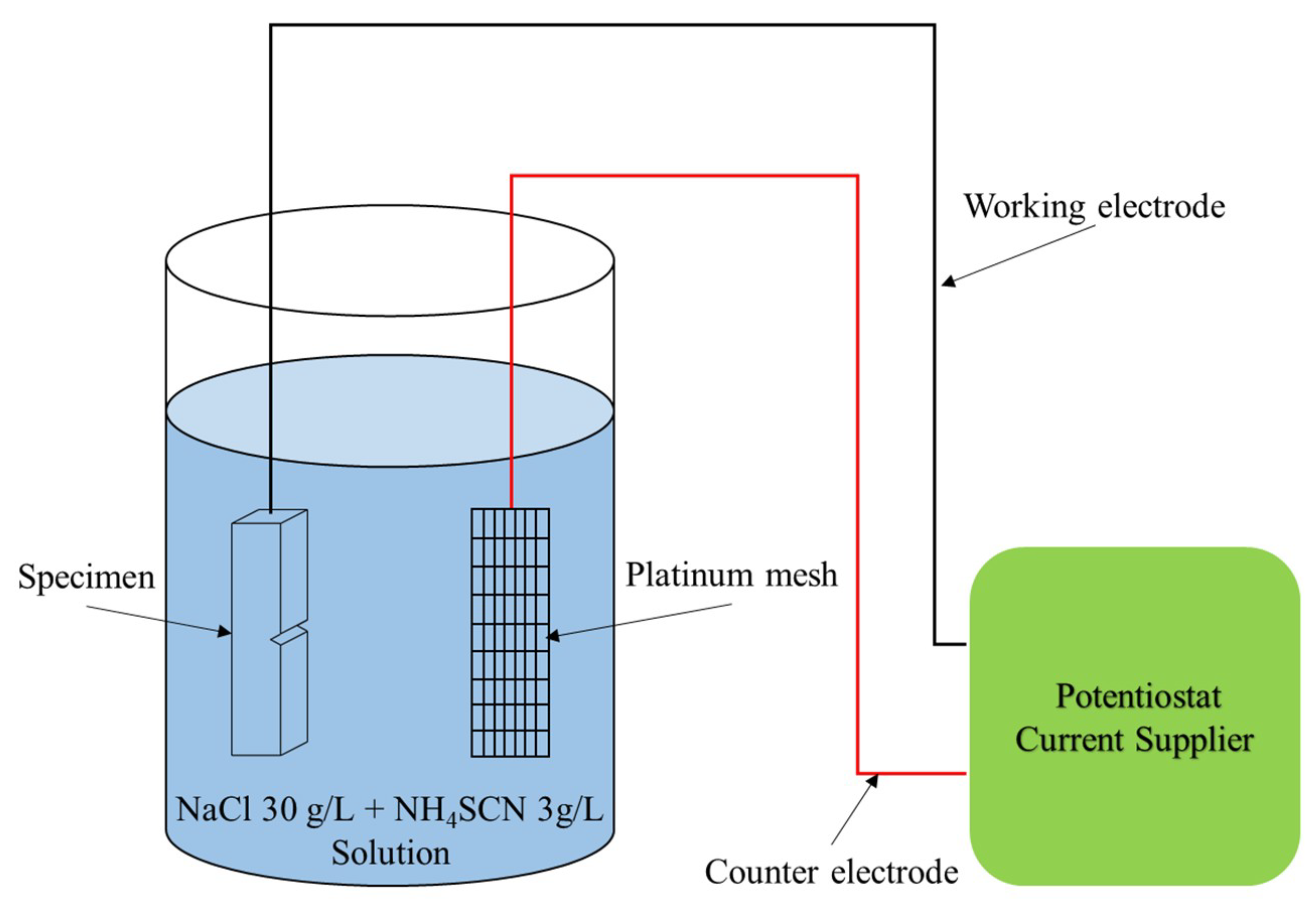
The two predominant methods used to generate HE in specimens are electrochemical charging and hydrogen gas charging. Hydrogen gas charging involves exposing the specimen to hydrogen atmosphere, while electrochemical hydrogen charging, or cathodic hydrogen charging, is a method by which a specimen is immersed in an electrolytic solution. Electricity is then used to generate water electrolysis. Cathodic hydrogen charging was used herein to generate HE in the 316L stainless steel specimens because this method was simple to perform. Cathodic hydrogen charging was conducted based on the ISO 16573-2015: Steel—Measurement method for the evaluation of HE resistance of high-strength steels [22]. The generated hydrogen diffused into the specimen surface, which played a role as a cathode. A platinum mesh was used as an anode. The notched specimens were totally immersed in the electrolyte solution composed of 3% NaCl + 0.3% NH4SCN. The NaCl molecules in the H2O solvent were dissolved to Na+ and Cl− ions, which acted as electrolytes in the solution, while NH4SCN prevented the H+ ions from recombination to H2 during hydrogen charging [23]. The charging’s current density was kept constant at 20 A/m2 using the potentiostat mode of a WBCS3000S Standard Type Battery Cycler (WonATech, Seoul, Korea). The charging durations were 12 h, 24 h and 48 h. Hydrogen was liberated at the cathode surface (specimen) and might diffuse into the specimen. The amount of liberated hydrogen depended on the current density. A larger current density liberated more hydrogen on the specimen surface. Figure 3 illustrates the schematic diagram of hydrogen charging for the V-notched specimens.
After the hydrogen exposure, each specimen was slightly polished by a grit sanding sponge after being charged to remove the little dirt on the specimen surface. Next, zinc electroplating was conducted to prevent hydrogen from being desorbed. The thin Zn layer acted as a barrier that prevents hydrogen from diffusing out during the loading test. The schematic diagram of the electroplating was the same as the hydrogen charging, except for the current density and the plating solution. In this procedure, the applied current density was 300 A/m2. The plating solution included Zn2+ ions, which were referenced from the ISO 16573-2015 standard [22]. Each specimen was initially electroplated for approximately 8 min. The specimen was then rotated and continued to be electroplated again in approximately 8 min to ensure that the Zn layer homogeneously covered the specimen. The electroplating times could be slightly adjusted to make sure that the Zn layers sufficiently covered the specimens with homogeneous thicknesses. Figure 4 illustrates the specimens before (a) and after (b) electroplating.
2.4. Hydrogen Concentration Measurement
After being hydrogen pre-charged, the hydrogen concentration on the surface of each specimen was measured by a ONH-2000 hydrogen analyzer (ELTRA GmbH, Haan, Germany) for the 12 h, 24 h and 48 h charged and uncharged specimens. For this measurement, each sample has 1 g in weight was cut from the specimen surface. The samples were then investigated for hydrogen concentration for approximately 2.5 min inside the dual range thermal conductivity cell of the hydrogen analyzer. At least five samples were analyzed for each duration of hydrogen exposure to ascertain the repeatability of the hydrogen concentration results. The hydrogen concentration was used to unveil the relationship between the absorbed energy and the hydrogen concentration for each CVN specimen.
2.5. CVN Impact Test
After being electroplated, the specimens were prepared by controlling the desired temperature conditions. Then, the Charpy impact tests were conducted. The CVN impact test demonstrated the absorbed energy during the material fracture, which also indicated work needed to make the material fracture at the experimental temperature of the CVN impact test. The absorbed energy was calculated as follows:
where ECVN is the absorbed energy; M is the mass of the hammer; R is the specimen length; β is the angle after the impact; α is the falling angle before the impact; and g is the gravitational acceleration. The absorbed energy of the specimens was recorded to estimate the toughness and ductility of the impact tests. Ductile fracture has high absorbed energy in the CVN impact test as well as better impact toughness, while brittle fracture has low absorbed energy in the CVN impact test. Therefore, the ductile fracture was preferred in most applications. Aside from the specimens used for the CVN impact test at the ambient temperature, the others were pre-cooled in the desired low temperature for 40–50 min to ensure their thermal equilibrium. To lower the temperature to −50 °C and −125 °C for the low-temperature impact test, liquefied nitrogen (LN2) was injected to an insulated chamber and the inlet flow rate of nitrogen was automatically adjusted to maintain the desired temperature by the two thermocouples connected to a computer. For −196 °C, the specimens were directly immersed to liquid nitrogen at atmospheric pressure in another insulated chamber. After pre-cooling for 40–50 min, the CVN impact test was conducted within 5 s for each specimen since the time that each specimen was brought out of the insulated chamber [17]. Each case was repeated at least three times to ensure the reliability of the testing results. Figure 5 presents the experimental procedure of the CVN impact test. Table 2 illustrates the experimental scenario of the hydrogen pre-charging, zinc electroplating and CVN impact tests.
ECVN = MR(cosβ − cosα)g,
2.6. Scanning Electron Microscopy (SEM)
For each case of the CVN impact test, a Supra 25 scanning electron microscope (Carl Zeiss AG, Oberkochen, Germany) was used to analyze the microstructure in the middle of the fracture surfaces after the impact test. This step focuses on the effect of the hydrogen charging time on the surface morphology (e.g., tortuousness, depth and size of dimples) on the specimen’s fracture surface after the CVN impact test. ImageJ software was employed to measure the dimple size. The absorbed energy and microstructure combination could unveil the impact properties of the specimens. The microstructure of the ductile fracture mainly has a tortuous appearance with large and deep dimples. In contrast, the brittle fracture microstructure mainly contains small spherical dimples and cleavage facets.
3. Results and Discussion
3.1. Hydrogen Concentration in the Specimens
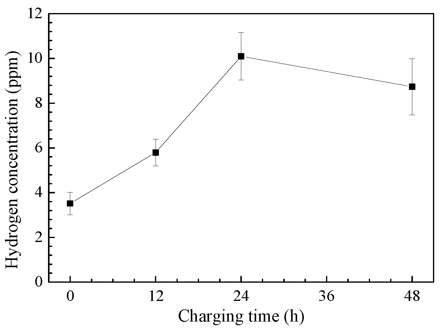
Figure 6 illustrates the hydrogen concentration at the surface of the uncharged and 12 h, 24 h and 48 h pre-charged specimens. This chart shows that the hydrogen concentration in the charged specimens was higher than that in the uncharged specimens. The average hydrogen concentration in the uncharged samples was 3.52 wt. ppm, which was approximate to that in the previous research [24]. In comparison with the non-exposed samples, the results for the 12 h, 24 h and 48 h charged samples are 5.79, 10.1 and 8.74 wt. ppm, which correspond to 164%, 287% and 248%, respectively. The hydrogen concentration dramatically increased and reached a saturation point at 24 h of charging. After 24 h of charging, the hydrogen concentration remained relatively closed to the saturated concentration of hydrogen. Besides, the errors of hydrogen concentration were relatively large. This result confirmed the high resistance of 316L stainless steel to HE because hydrogen hardly diffused into this material and was homogeneously distributed on the thin outer layer of the hydrogen-exposed specimens. The next section explains the effect of the hydrogen charging time and the temperature of the CVN impact test on the absorbed energy of 316L stainless steel.
3.2. CVN Impact Absorbed Energy
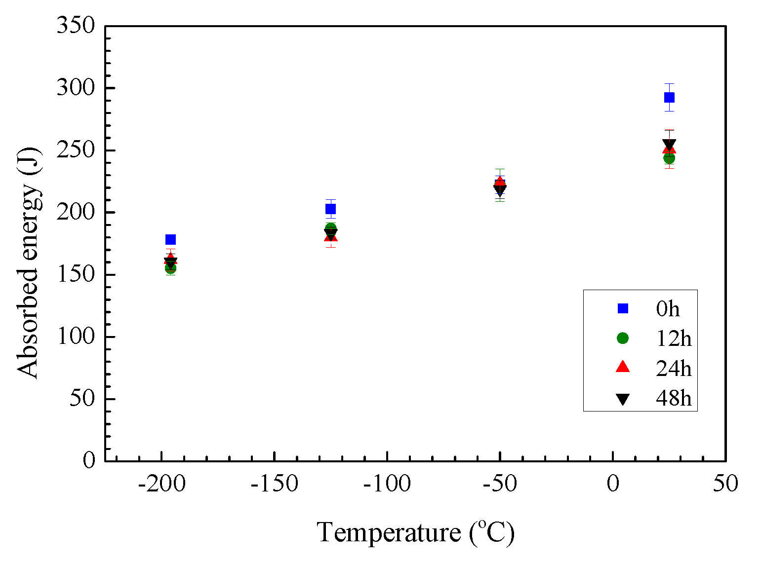
In a CVN impact test, the ductile fracture has higher absorbed energy and higher plastic deformation than the brittle fracture. Figure 7 shows the temperature-dependent absorbed energy of the CVN impact test for the 12 h, 24 h and 48 h hydrogen charged and uncharged 316L stainless steel at 25 °C (ambient temperature), −50 °C, −125 °C and −196 °C, respectively.
Overall, the tested 316L stainless steel’s absorbed energy gradually decreased when decreasing the temperature of the CVN impact test. Specifically, in comparison with 25 °C, the average absorbed energy of the uncharged specimens at −50 °C, −125 °C and −196 °C are 76.0%, 69.4% and 61.0% respectively. These ratios for the 12 h, 24 h and 48 h charged specimens were approximate to those of the uncharged specimens. Therefore, the ductility of impact tests decreased gradually from ambient temperature to −196 °C. The decrease in the absorbed energy as well as the ductility was caused by lowering the temperature of impact tests, which resulted in the more brittle fracture of 316L stainless steel [25,26].
Figure 8 shows the charging time-dependent absorbed energy behavior of 316L stainless steel at 25 °C (ambient temperature), −50 °C, −125 °C and −196 °C, respectively. At the same temperature of the CVN impact test, the absorbed energy of the pre-charged specimens relatively dropped in comparison to that of the uncharged specimens. For the CVN impact test conducted at the ambient temperature, the drop in the absorbed energies at the 12 h, 24 h and 48 h charged specimens corresponded to 16.6%, 14.2% and 12.6%, respectively, when compared to those in the uncharged specimens. This result also indicates that hydrogen pre-charging slightly decreased the ductility of the notched specimens at the ambient temperature.
For the CVN impact test conducted at −50 °C, the absorbed energy for the pre-charged specimens was almost alike to the uncharged specimens. Specifically, the dropped ratio for the CVN impact test for the 12 h and 48 h pre-charged specimens is approximately 0.23% and 1.7% respectively, compared to the uncharged specimens. The absorbed energy for the 24 h pre-charged specimen increased by 0.45%. Therefore, the effect of hydrogen pre-charging at −50 °C was negligible.
At −125 °C, the absorbed energy also exhibited a slight decrease with the pre-charging time of hydrogen. The drop in the absorbed energy is 7.9%, 11.3% and 9.7% for the 12 h, 24 h and 48 h pre-charged specimens, respectively. Finally, at −196 °C, the drop in the absorbed energy for the 12 h, 24 h and 48 h pre-charged specimens is 12.9%, 9.2% and 10.0%, respectively. Overall, most of the hydrogen pre-charged specimens exhibited a drop in the absorbed energy, indicating that hydrogen pre-charging decreased the ductility of 316L stainless steel in the CVN impact tests at the ambient temperature, −50 °C, −125 °C and −196 °C. Former studies also revealed that hydrogen exposure changes the fracture mode of materials from ductile to brittle [2,27] and therefore decreased the absorbed energy in the CVN impact test of metallic materials. In Figure 7 and Figure 8, the exposure to hydrogen decreased the absorbed energy in the CVN impact tests but the drop in absorbed energy remained stable from 24 h to 48 h of charging, which reflected a similar behavior with hydrogen concentration in 24 h charged and 48 h charged specimens. A former study also revealed that when increasing the hydrogen outgassing time to low carbon stainless steel, not much difference in hardness of the specimens was observed [28].
3.3. Fracture Surface Morphology
Figure 9 illustrates the specimens under CVN impact tests. In Figure 9, cracks were found on the V-notched specimen after the CVN impact test. The appearance of the cracks mostly depended on the temperature of the impact tests. The presence of plastic deformation increased in the order of −196 °C, −125 °C, −50 °C and ambient temperature. For CVN impact tests conducted at −196 °C, all V-notched specimens were separated into 2 pieces and showed very little plastic deformation. The specimens in CVN impact tests conducted at −125 °C and −50 °C were partly separated by the impact tests and showed relatively little plastic deformation. Meanwhile, impact tests conducted at ambient temperature showed extensive plastic deformation and all specimens were not separated. Further, the differences in the appearance of impacted specimens according to charging times were not clear.
Scanning electron microscopy was conducted after the CVN impact test to investigate the fracture surface of the specimens. The brittle fracture has little plastic deformation and mainly contains small spherical dimples, flat facets and cleavage facets on the fracture surfaces. For ductile fracture, the fracture surface mainly includes a tortuous appearance with deep and large dimples. The ductile fracture has more plastic deformation than the brittle fracture. Therefore, the absorbed energy in the CVN impact test of ductile fracture was higher than that of brittle fracture.
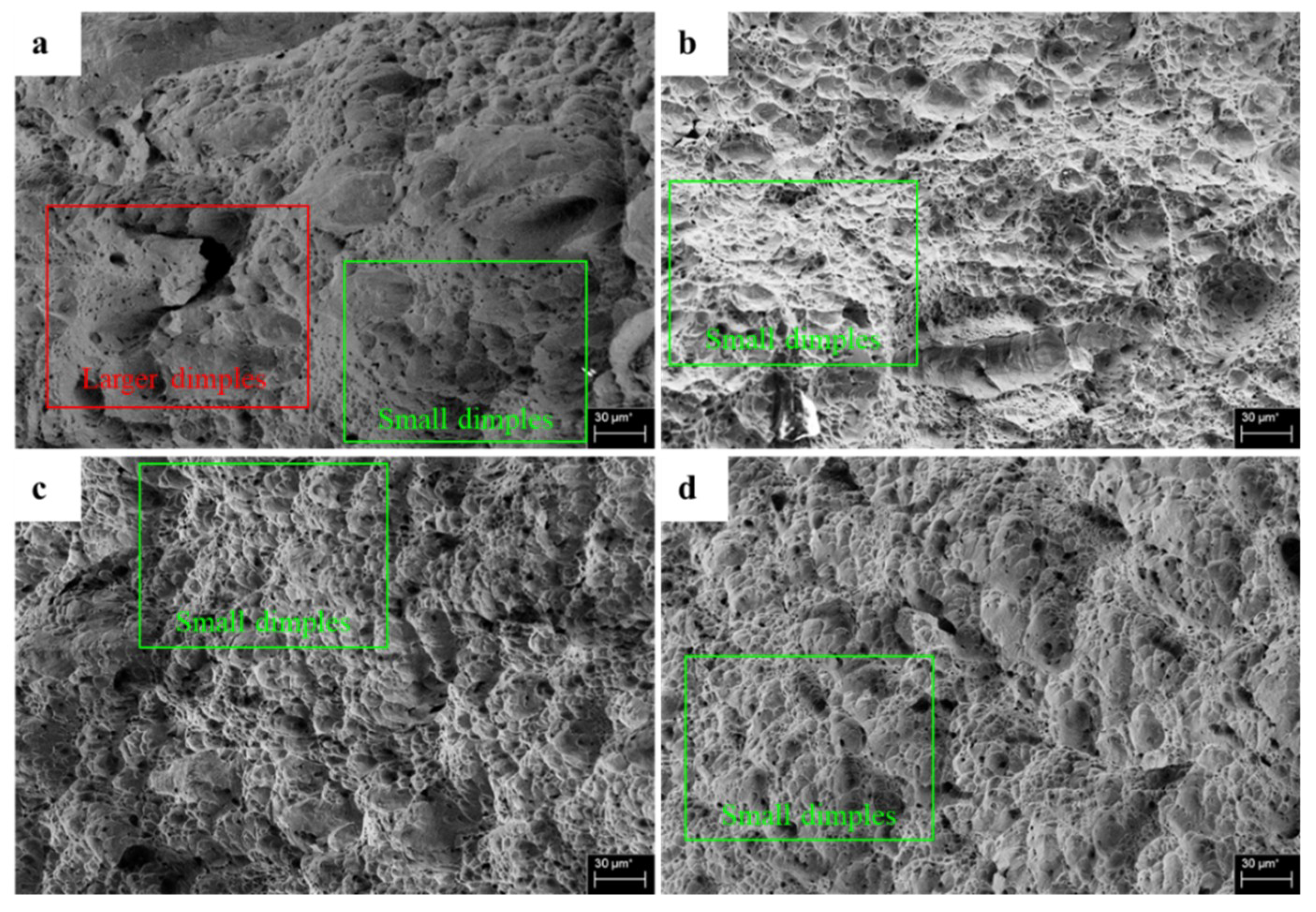
Figure 10 shows the fracture surfaces for the impact test conducted at ambient temperature for the (a) uncharged, (b) 12 h charged, (c) 24 h charged and (d) 48 h charged specimens after the CVN impact test. As shown in this figure, the fracture surfaces have a tortuous appearance and mainly covered by large dimples. The cleavage fracture was not observed in the SEM images at ambient temperature and the large dimples were relatively deep. Those were the signs of plastic deformation. Therefore, at ambient temperature, the type of impact fracture was mainly ductile. For different charging times, the morphology of the uncharged specimen was the roughest appearance by included many tortuous and large dimples, the depth of those dimples was bigger than the other charged specimens, which confirms the negligible drop in absorbed energy of charged specimens at ambient temperature. Besides, the dimples on the fracture surface of 12 h charged specimen were relatively smaller and shallower than the other specimens at ambient temperature, confirms that the absorbed energy of 12 h charged specimen was the smallest among the charging time. Therefore, the effect charging times at 12 h on the surface morphology as well as deformation of CVN impact tests at ambient temperature was the largest, followed by 24 h and 48 h charging time. Besides, there were negligible differences between the deformation as well as absorbed energy between 24 h charged specimen and 48 h charged specimen at ambient temperature.
Figure 11 shows the microstructure analysis of the fracture surface in the CVN impact test at −50 °C. The fracture surfaces at −50 °C are primarily covered by relatively large dimples. However, the fracture surface at this temperature was less circuitous than that in the ambient temperature, the dimples in Figure 11 are relatively smaller and shallower than the dimples in Figure 10 and an increased presence of the small spherical dimples and flat facets was observed. Thus, this appearance of the fracture surfaces indicated that the deformation was less ductile in the impact tests at −50 °C than that at the ambient temperature and led to a drop in the absorbed energy from the ambient temperature to −50 °C in Figure 7. Moreover, the appearance of the fracture surfaces in Figure 11 are made quite analogous, confirming that the impact properties of specimens at −50 °C are roughly alike. Overall, the effect of hydrogen pre-charging on the CVN impact properties of 316L stainless steel at −50 °C was negligible. The drop in the absorbed energy from the ambient temperature to −50 °C was caused by the decrease in the temperature of the CVN impact test.
Figure 12 illustrates the microstructure images of the fracture surface in the CVN impact test at −125 °C of 316L stainless steel according to the hydrogen charging time. As shown in this figure, the fracture surfaces were mainly covered by small spherical dimples. The presence of the small and spherical dimple fracture was more frequent here than in the ambient temperature and −50 °C, making the average size of dimples at −125 °C smaller than at the ambient temperature and −50 °C and the spherical dimples are relatively shallow. Thus, this appearance of the fracture surfaces indicated that the CVN impact behavior at −125 °C was more brittle than at the ambient temperature and −50 °C, confirming that the average absorbed energy at −125 °C was smaller than at −50 °C. Besides, there were differences in the fracture surface according to the charging times. The surface morphology of the uncharged specimen was rougher than the charged specimens. Specifically, the size of dimples of the uncharged specimen was relatively larger and deeper, which confirms the drop in absorbed energy of charged specimens at −125 °C. In addition, the fracture surfaces of the charged specimens in Figure 12 are roughly alike, which mainly covered by small spherical dimples. Therefore, the surface morphology and the average size of dimples confirmed that hydrogen pre-charging degraded the impact toughness and surface morphology of the CVN impact test conducted at −125 °C but the differences among the charged specimens were negligible.
Figure 13 illustrates the microstructure images on the fracture surface in the CVN impact test at −196 °C. The appearance of the fracture surfaces in this figure is dominated by small and spherical dimples, which are smaller and more circular than those in the fracture surface of the impact tests conducted at the ambient temperature, −50 °C and −125 °C. Besides, the deep and large dimples are rarely observed herein, confirming that the type of fracture at −196 °C was the least ductile fracture among the tested temperatures. That is, this was the reason why the absorbed energy in the CVN impact test at −196 °C was the smallest among the tested temperatures.
Among the SEM images in Figure 13, the uncharged specimen’s size and depth were largest among the fracture surfaces obtained from the impact test at −196 °C, confirming that the type of fracture of the uncharged specimen at −196 °C was the most ductile fracture. Besides, the differences among the fracture surfaces the charged specimens were not noticeable. That is, they were covered by similar shallow and small spherical dimples, confirming that hydrogen exposure decreased the ductility and the absorbed energy of the charged specimens in the CVN impact test at −196 °C.
4. Conclusions
The CVN impact behavior of the hydrogen-exposed 316L stainless steel at the ambient temperature, −50 °C, −125 °C and −196 °C was studied herein. The following conclusions can be drawn from this study:
- Exposure to hydrogen increased the hydrogen concentration of the samples collected at the specimen surface. After 24 h of charging, the hydrogen concentration in the charged specimens reached a saturation point.
- Hydrogen charging resulted in a slight reduction in the absorbed energy and ductility of 316L stainless steel at most of the tested specimens. The drop in absorbed energy varied from 0.23% to 16.6%.
- The surface morphology of the uncharged specimens was more ductile than that of the pre-charged specimens impacted at ambient temperature, −125 °C and −196 °C. While the differences for specimens impacted at −50 °C were negligible.
- Another academic insight obtained herein is that low temperature decreased the ductility of the V-notched specimens in the CVN impact test. The loss of ductility caused by the ductile to brittle transformation was attributed to the lowering of the temperature in the CVN impact tests.
Therefore, the impact properties of 316L stainless steel have a high resistance against HE and this material can be a possible candidate as material for the hydrogen containment system. However, using 316L stainless steel at low temperature should be carefully considered because of the losses in ductility and fracture resistance caused by this low temperature. Former studies investigated the effect of HE on the mechanical properties of materials. A standard for the absorbed energy of hydrogen-exposed materials in specific temperature ranges must be surveyed and created. The results of this study could contribute to the research database for hydrogen tanks, hydrogen pipelines and fuel cell vehicles containing 316L stainless steel.
Author Contributions
L.T.H.N. wrote the paper, designed the testing program and performed CVN impact tests. J.S.H. coordinated the sample acquisition, specimen machining, measured hydrogen concentration. M.S.K. prepared the experimental testing facility and analyzed impact test results. J.H.K. optimized experimental setup for microstructure analysis and contributed reviewing the original manuscript. S.K.K. optimized experimental setup for CVN impact tests and contributed reviewing the original manuscript. J.M.L. supervised the experiments and contributed reviewing the original manuscript.
Funding
This work was supported by the National Research Foundation of Korea (NRF) grant funded by the Ministry of Science and ICT (MSIT) (No. 2018R1A2B6007403). This work was also supported by the National Research Foundation of Korea (NRF) grant funded by the Korea government (MSIT) through GCRC-SOP (No. 2011-0030013).
Conflicts of Interest
The authors declare no conflicts of interest.
References
- Marine Environment Protection Committee (MEPC), 72nd session, 9–13 April 2018. Available online: http://www.imo.org/en/MediaCentre/MeetingSummaries/MEPC/Pages/MEPC-72nd-session.aspx (accessed on 14 April 2019).
- Dwivedi, S.K.; Vishwakarma, M. Hydrogen embrittlement in different materials: A review. Int. J. Hydrogen Energy 2018, 43, 21603–21616. [Google Scholar] [CrossRef]
- Michler, T.; Lee, Y.; Gangloff, R.P.; Naumann, J. Influence of macro segregation on hydrogen environment embrittlement of SUS 316L stainless steel. Int. J. Hydrogen Energy 2009, 34, 3201–3209. [Google Scholar] [CrossRef]
- Czarkowski, P.; Krawczynska, A.T.; Slesinski, R.; Brynk, T.; Budniak, J.; Lewandowska, M.; Kurzydlowski, K.J. Low temperature mechanical properties of 316L type stainless steel after hydrostatic extrusion. Fusion Eng. Des. 2011, 86, 2517–2521. [Google Scholar] [CrossRef]
- Nagumo, M. Fundamentals of Hydrogen Embrittlement; Springer: Berlin, Germany, 2016; ISBN 9789811001611. [Google Scholar]
- Fukuyama, S.; Zhang, L.; Yokogawa, K. Development of Materials Testing Equipment in High Pressure Hydrogen and Hydrogen Environment Embrittlement of Austenitic Stainless Steels. Jpn. Inst. Met. 2004, 68, 62–65. [Google Scholar] [CrossRef] [Green Version]
- Kanezaki, T.; Narazaki, C.; Mine, Y.; Matsuoka, S.; Murakami, Y. Effects of hydrogen on fatigue crack growth behavior of austenitic stainless steels. Int. J. Hydrogen Energy 2008, 33, 2604–2619. [Google Scholar] [CrossRef]
- Weber, S.; Martin, M.; Theisen, W. Lean-alloyed austenitic stainless steel with high resistance against hydrogen environment embrittlement. Mater. Sci. Eng. A 2011, 528, 7688–7695. [Google Scholar] [CrossRef]
- Sugiyama, S.; Ohkubo, H.; Takenaka, M.; Ohsawa, K.; Ansari, M.I.; Tsukuda, N.; Kuramoto, E. The effect of electrical hydrogen charging on the strength of 316 stainless steel. J. Nucl. Mater. 2000, 283–287, 863–867. [Google Scholar] [CrossRef]
- Rozenak, P.; Eliezer, D. Phase changes related to hydrogen-induced cracking in austenitic stainless steel. Acta Metall. 1987, 35, 2329–2340. [Google Scholar] [CrossRef]
- Rozenak, P.; Robertson, I.M.; Birnbaum, H.K. HVEM studies of the effects of hydrogen on the deformation and fracture of AISI type 316 austenitic stainless steel. Acta Metall. Mater. 1990, 38, 2031–2040. [Google Scholar] [CrossRef]
- Garber, R.; Bernstein, I.M.; Thompson, A.W. Effect of hydrogen on ductile fracture of spheroidized steel. Scr. Metall. 1976, 10, 341–345. [Google Scholar] [CrossRef]
- Venezuela, J.; Tapia-Bastidas, C.; Zhou, Q.; Depover, T.; Verbeken, K.; Gray, E.; Liu, Q.; Liu, Q.; Zhang, M.; Atrens, A. Determination of the equivalent hydrogen fugacity during electrochemical charging of 3.5NiCrMoV steel. Corros. Sci. 2018, 132, 90–106. [Google Scholar] [CrossRef] [Green Version]
- Matsuo, T.; Yamabe, J.; Matsuoka, S. Effects of hydrogen on tensile properties and fracture surface morphologies of Type 316L stainless steel. Int. J. Hydrogen Energy 2014, 39, 3542–3551. [Google Scholar] [CrossRef]
- Yamabe, J.; Takakuwa, O.; Matsunaga, H.; Itoga, H.; Matsuoka, S. Hydrogen diffusivity and tensile-ductility loss of solution-treated austenitic stainless steels with external and internal hydrogen. Int. J. Hydrogen Energy 2017, 42, 13289–13299. [Google Scholar] [CrossRef]
- Momotani, Y.; Shibata, A.; Terada, D.; Tsuji, N. Effect of strain rate on hydrogen embrittlement in low-carbon martensitic steel. Int. J. Hydrogen Energy 2017, 42, 3371–3379. [Google Scholar] [CrossRef]
- ASTM Standard Test Methods for Notched Bar Impact Testing of Metallic Materials; ASTM International: West Conshohocken, PA, USA, 2016.
- Rossoll, A.; Berdin, C.; Forget, P.; Prioul, C.; Marini, B. Mechanical aspects of the Charpy impact test. Nucl. Eng. Des. 1999, 188, 217–229. [Google Scholar] [CrossRef] [Green Version]
- Fassina, P.; Bolzoni, F.; Fumagalli, G.; Lazzari, L.; Vergani, L.; Sciuccati, A. Influence of hydrogen and low temperature on pipeline steels mechanical behaviour. Procedia Eng. 2011, 10, 3226–3234. [Google Scholar] [CrossRef]
- Mori, K.; Lee, E.W.; Frazier, W.E.; Niji, K.; Battel, G.; Tran, A.; Iriarte, E.; Perez, O.; Ruiz, H.; Choi, T.; et al. Effect of Tempering and Baking on the Charpy Impact Energy of Hydrogen-Charged 4340 Steel. J. Mater. Eng. Perform. 2015, 24, 329–337. [Google Scholar] [CrossRef]
- Rosenberg, G.; Sinaiova, I. Evaluation of hydrogen induced damage of steels by different test methods. Mater. Sci. Eng. A 2017, 682, 410–422. [Google Scholar] [CrossRef]
- ISO 16573:2015. Steel—Measurement Method for the Evaluation of Hydrogen Embrittlement Resistance of High Strength Steels; International Organization for Standardization: Geneva, Switzerland, 2015. [Google Scholar]
- Jeon, H.H.; Lee, S.M.; Han, J.; Park, I.J.; Lee, Y.K. The effect of Zn coating layers on the hydrogen embrittlement of hot-dip galvanized twinning-induced plasticity steel. Corros. Sci. 2016, 111, 267–274. [Google Scholar] [CrossRef]
- Brass, A.M.; Chêne, J. Hydrogen uptake in 316L stainless steel: Consequences on the tensile properties. Corros. Sci. 2006, 48, 3222–3242. [Google Scholar] [CrossRef]
- Byun, T.S.; Lach, T.G. Mechanical Properties of 304L and 316L Austenitic Stainless Steels after Thermal Aging for 1500 Hours; U.S. Department of Energy/Office of Nuclear Energy: District of Columbia, WA, USA, 2016; pp. 1–19.
- Kim, J.H.; Choi, S.W.; Park, D.H.; Lee, J.M. Charpy impact properties of stainless steel weldment in liquefied natural gas pipelines: Effect of low temperatures. Mater. Des. 2015, 65, 914–922. [Google Scholar] [CrossRef]
- Djukic, M.B.; Zeravcic, V.S.; Bakic, G.; Sedmak, A.; Rajicic, B. Hydrogen Embrittlement of Low Carbon Structural Steel. Procedia Mater. Sci. 2014, 3, 1167–1172. [Google Scholar] [CrossRef] [Green Version]
- Godoi, W.; Kuromoto, N.K.; Guimaraes, A.S.; Lepienski, C.M. Effect of the hydrogen outgassing time on the hardness of austenitic stainless steels welds. Mater. Sci. Eng. A 2003, 354, 251–256. [Google Scholar] [CrossRef]
Figure 1.
Schematic diagram of a hydrogen container.

Figure 2.
(a) Photograph and (b) dimension of the V-notched specimen (unit: mm).

Figure 3.
Schematic diagram of the cathodic hydrogen charging.

Figure 4.
Charpy V-notch (CVN) impact specimens before (a) and after (b) electroplating.

Figure 5.
Experimental procedure of the CVN impact test.

Figure 6.
Hydrogen concentration at the uncharged and 12 h, 24 h and 48 h charged specimens.

Figure 7.
Temperature-dependent absorbed energy behavior of 316L stainless steel for uncharged, 12 h charged, 24 h charged and 48 h charged specimens (the error bars indicate the incertitude of the absorbed energy).
Figure 7.
Temperature-dependent absorbed energy behavior of 316L stainless steel for uncharged, 12 h charged, 24 h charged and 48 h charged specimens (the error bars indicate the incertitude of the absorbed energy).

Figure 8.
Charging time-dependent absorbed energy behavior of 316L stainless steel at 25 °C (ambient temperature), −50 °C, −125 °C and −196 °C (the error bars indicate the incertitude of the absorbed energy).
Figure 8.
Charging time-dependent absorbed energy behavior of 316L stainless steel at 25 °C (ambient temperature), −50 °C, −125 °C and −196 °C (the error bars indicate the incertitude of the absorbed energy).

Figure 9.
Photograph of tested specimens.

Figure 10.
Scanning electron microscope (SEM) images obtained from the impact test at the ambient temperature: (a) uncharged, (b) 12 h charged, (c) 24 h charged and (d) 48 h charged.
Figure 10.
Scanning electron microscope (SEM) images obtained from the impact test at the ambient temperature: (a) uncharged, (b) 12 h charged, (c) 24 h charged and (d) 48 h charged.

Figure 11.
Scanning electron microscope (SEM) images obtained from the impact test at −50 °C: (a) uncharged, (b) 12 h charged, (c) 24 h charged and (d) 48 h charged.
Figure 11.
Scanning electron microscope (SEM) images obtained from the impact test at −50 °C: (a) uncharged, (b) 12 h charged, (c) 24 h charged and (d) 48 h charged.

Figure 12.
Scanning electron microscope (SEM) images obtained from the impact test at −125 °C: (a) uncharged, (b) 12 h charged, (c) 24 h charged and (d) 48 h charged.
Figure 12.
Scanning electron microscope (SEM) images obtained from the impact test at −125 °C: (a) uncharged, (b) 12 h charged, (c) 24 h charged and (d) 48 h charged.
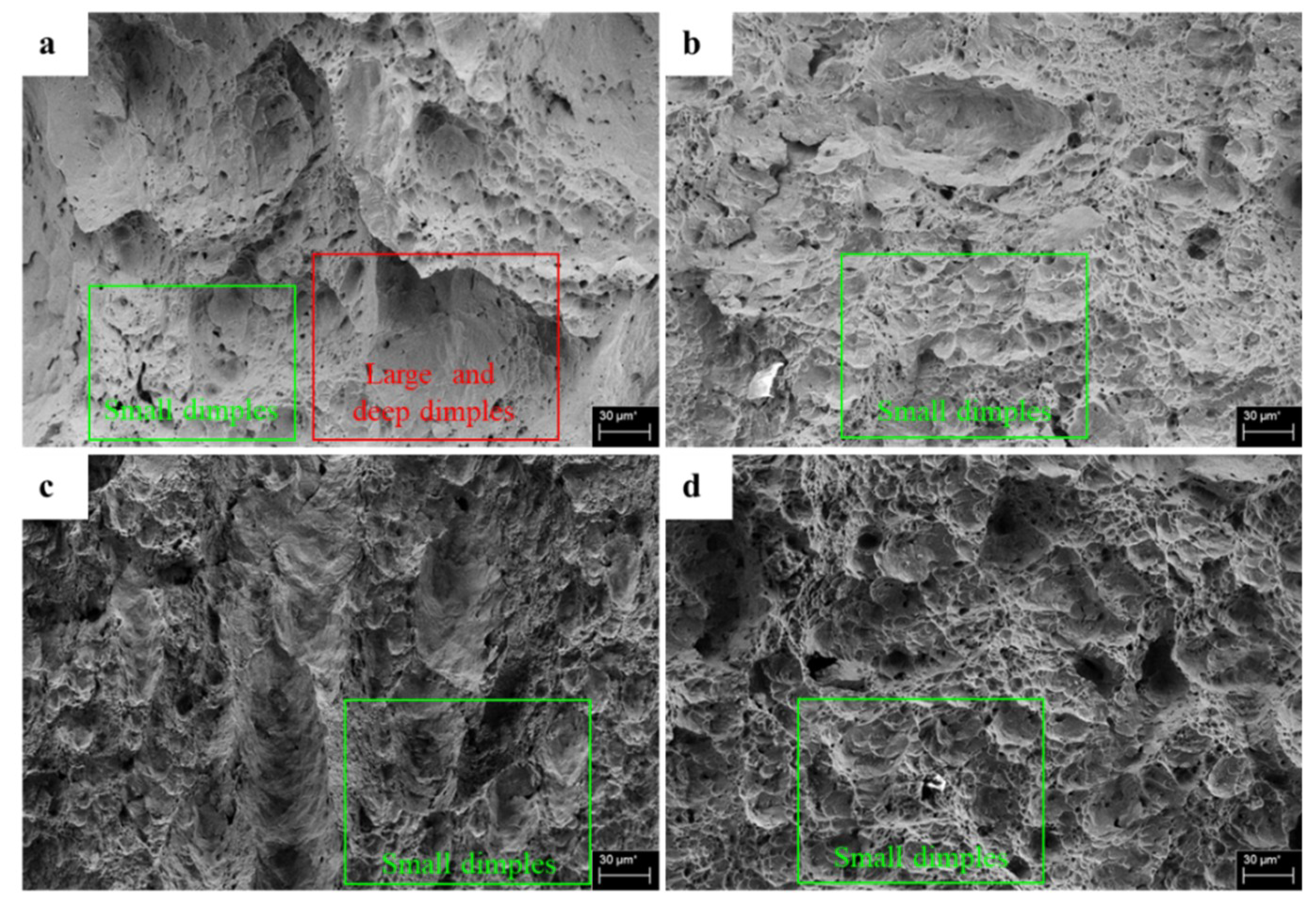
Figure 13.
Scanning electron microscope (SEM) images obtained from the impact test at −196 °C: (a) uncharged, (b) 12 h charged, (c) 24 h charged and (d) 48 h charged.
Figure 13.
Scanning electron microscope (SEM) images obtained from the impact test at −196 °C: (a) uncharged, (b) 12 h charged, (c) 24 h charged and (d) 48 h charged.


Table 1.
Composition of 316L stainless steel.
| Specimen | Chemical Elements (wt. %) | ||||||||
|---|---|---|---|---|---|---|---|---|---|
| C | Si | S | P | Mn | Mo | Ni | Cr | Fe | |
| 316L | 0.020 | 0.56 | 0.003 | 0.028 | 1.33 | 2.1 | 10.19 | 16.4 | Bal. |
Table 2.
Experimental scenario.
| No | Charging Current Density (A/m2) | Charging Duration (h) | Electroplating Current Density (A/m2) | Temperature of CVN Impact Test (°C) |
|---|---|---|---|---|
| 1 | 0 | 0 | 0 | 25 |
| 2 | 20 | 12 | 300 | |
| 3 | 24 | |||
| 4 | 48 | |||
| 5 | 0 | 0 | 0 | −50 |
| 6 | 20 | 12 | 300 | |
| 7 | 24 | |||
| 8 | 48 | |||
| 9 | 0 | 0 | 0 | −125 |
| 10 | 20 | 12 | 300 | |
| 11 | 24 | |||
| 12 | 48 | |||
| 13 | 0 | 0 | 0 | −196 |
| 14 | 20 | 12 | 300 | |
| 15 | 24 | |||
| 16 | 48 |
© 2019 by the authors. Licensee MDPI, Basel, Switzerland. This article is an open access article distributed under the terms and conditions of the Creative Commons Attribution (CC BY) license (http://creativecommons.org/licenses/by/4.0/).
Share and Cite
MDPI and ACS Style
Nguyen, L.T.H.; Hwang, J.-S.; Kim, M.-S.; Kim, J.-H.; Kim, S.-K.; Lee, J.-M. Charpy Impact Properties of Hydrogen-Exposed 316L Stainless Steel at Ambient and Cryogenic Temperatures. Metals 2019, 9, 625. https://doi.org/10.3390/met9060625
AMA Style
Nguyen LTH, Hwang J-S, Kim M-S, Kim J-H, Kim S-K, Lee J-M. Charpy Impact Properties of Hydrogen-Exposed 316L Stainless Steel at Ambient and Cryogenic Temperatures. Metals. 2019; 9(6):625. https://doi.org/10.3390/met9060625
Chicago/Turabian StyleNguyen, Le Thanh Hung, Jae-Sik Hwang, Myung-Sung Kim, Jeong-Hyeon Kim, Seul-Kee Kim, and Jae-Myung Lee. 2019. "Charpy Impact Properties of Hydrogen-Exposed 316L Stainless Steel at Ambient and Cryogenic Temperatures" Metals 9, no. 6: 625. https://doi.org/10.3390/met9060625
Note that from the first issue of 2016, this journal uses article numbers instead of page numbers. See further details here.