Article

Effect of Final Electromagnetic Stirring Parameters on Central Cross-Sectional Carbon Concentration Distribution of High-Carbon Square Billet

1
Anhui Province Key Laboratory of Metallurgical Engineering & Resources Recycling, Anhui University of Technology, Ma’anshan 243002, China
2
School of Metallurgical Engineering, Anhui University of Technology, Ma’anshan 243002, China
3
The State Key Laboratory of Refractories and Metallurgy, Wuhan University of Science and Technology, Wuhan 430081, China
4
Xinyu Iron and Steel Co., Ltd., Xinyu 338001, China
*
Authors to whom correspondence should be addressed.
Metals 2019, 9(6), 665; https://doi.org/10.3390/met9060665
Submission received: 4 May 2019 / Revised: 23 May 2019 / Accepted: 5 June 2019 / Published: 7 June 2019
(This article belongs to the Special Issue Advances in Metal Casting Technology)

Abstract

:
The effect of final electromagnetic stirring parameters, with current intensity increasing from 300 A to 400 A and frequency increasing from 4 Hz to 12 Hz, on the electromagnetic forces and carbon concentration distribution of the central cross section of a 70 steel square billet have been studied. Along the center line of the liquid core zone, current intensity of 400 A and frequency of 8 Hz achieve the maximum electromagnetic force at the position 48 mm away from the billet edge among the 10 groups of stirring parameters. Nevertheless, along diagonal of the liquid core zone, the electromagnetic force near the diagonal center is the greatest and the current intensity of 280 A and frequency of 12 Hz obtain the maximum electromagnetic force. The optimal final electromagnetic stirring (F-EMS) parameter to uniform the central cross-sectional carbon concentration and minimize the center carbon segregation of 70 steel billet was obtained with a current intensity of 280 A and frequency of 12 Hz. Under this stirring parameter, the area ratios of carbon concentrations of 0.66 wt%, 0.70 wt% and 0.74 wt% in the middle of the billet cross section reached 28.5%, 56.9% and 10.9%, respectively. Moreover, the carbon segregation indexes for all sampling points were in the range of 0.92–1.05.

1. Introduction

The high carbon steel tends to solidify over a large solidification temperature range and long solidification time. The macrosegregation and porosity defects produced during the solidification can be explained by the lesser volume of the components in the solid phase with respect to the liquid. [1,2]. As the diffusing time is so lengthy in practice, macrosegregation cannot be eliminated during subsequent soaking and the hot working process, and leads to poor or non-uniform mechanical properties in the finished products [3,4]. The presence of proeutectoid cementite in the pearlite matrix of a high carbon steel billet has been attributed to the center carbon segregation. Due to a tendency to martensitic transformation even at the moderate cooling rates, high carbon segregated regions will result in a cup and cone type failure during downstream deformation processing or premature failure of finished products in service [5,6,7,8].
In recent decades, many techniques have been proposed to minimize the detrimental center carbon segregation in high-carbon continuous casting, such as low temperature casting, intensive cooling at the solidification end, soft reduction, large reduction, and electromagnetic stirring (EMS) [9,10,11]. Among those techniques, the combination of mold and final electromagnetic stirring (M-EMS and F-EMS) is known as one of the most effective and widely used methods to eliminate the macrosegregation of high-carbon square billet. Therefore, many plant trials and laboratory experiments have been undertaken to investigate the role of EMS in macrosegregation improvement [12]. Suzuki et al. [13] applied some EMS experiments in small ingot casting and found that V-segregation could be improved by weak stirring. However, intensive stirring had some detrimental effects. Sun and Zhang [14] applied the continuum model to ascribe segregation formation to the floatation of solute-enriched molten steel and the washing effect of electromagnetic stirring. Luo et al. [15] studied the distribution of the electromagnetic field and flow field in final stirring zone and obtained the optimal stirring parameters. Jiang and Zhu [16] applied a multiphase solidification model to investigate F-EMS parameters on center segregation improvement, such as F-EMS current intensity, stirring pool width, and stirring mode. However, the relationship between final electromagnetic stirring parameters and cross-sectional carbon element distribution in a stirring zone of a high-carbon square billet has not previously been reported in literature, especially in a continuous casting process.
In the present work, the F-EMS model was developed for 160 mm × 160 mm continuous casting of high-carbon steel billets with the aid of commercial software ANSYS to investigate the distribution of the electromagnetic field. The morphology of cross and longitudinal sections was obtained by acid tech, and the concentration of solute element carbon at the central cross-section under different final electromagnetic stirring currents and frequencies were tested by the wet chemical and original position analyzer, and finally the optimal parameters of F-EMS for the continuously cast billet of 70 steel were determined.

2. Mathematical Model and Experimental Procedures

2.1. Electromagnetic Field Model

The F-EMS device with 750 mm height, 314 mm inner diameter, 604 mm outer diameter was installed in the secondary cooling zone of the caster. The generated electromagnetic field was obtained by solving Maxwell’s and constitutive equations, which are shown as Equation (1) [15]. The time-averaged electromagnetic force replaces the transient value, calculated by Equation (2). The electromagnetic forces on the center line and diagonal of the x–y plane at z = 0 mm, z = 112 mm, z = 224 mm and z = 336 mm, respectively, are calculated to demonstrate the stirring intensity of different final electromagnetic stirring parameters on the molten steel in the stirring zone, as shown in Figure 1. The physical properties and process parameters for the simulation are shown in Table 1.
{ · B = 0 · H = J · E = B t B = μ · H J = σ · E
F mag = 1 2 R e · J · B
where H (A/m) is the magnetic field intensity; J (A/m2) is induced current density in the strand; E (V/m) is the electric field intensity; B (T) is magnetic induction intensity; μ is the magnetic permeability; σ is the electric conductivity; Re is the real quantity of a complex expression; F mag (N/m3) is the electromagnetic force per unit volume.

2.2. Experimental Procedures

In this work, two positions, 8000 and 9100 mm below meniscus along the casting direction, respectively, were chosen to measure liquid core thickness of the billet at the inlet and outlet of the stirrer, as shown in Figure 2. The distance of the final electromagnetic stirrer inlet below the meniscus was 8180 mm. In each shooting position, the center along the width direction was the measuring point. After the slabs were cooled into the room temperature, the slab sections with nails were cut into slab samples of 100 mm length with a flame-cutting machine. Two slab samples were sent to the machining workshop to be further cut and milled until the nails can expose themselves clearly. Then the samples with nails were macroetched with 1:1 warm hydrochloric acid-water solution.
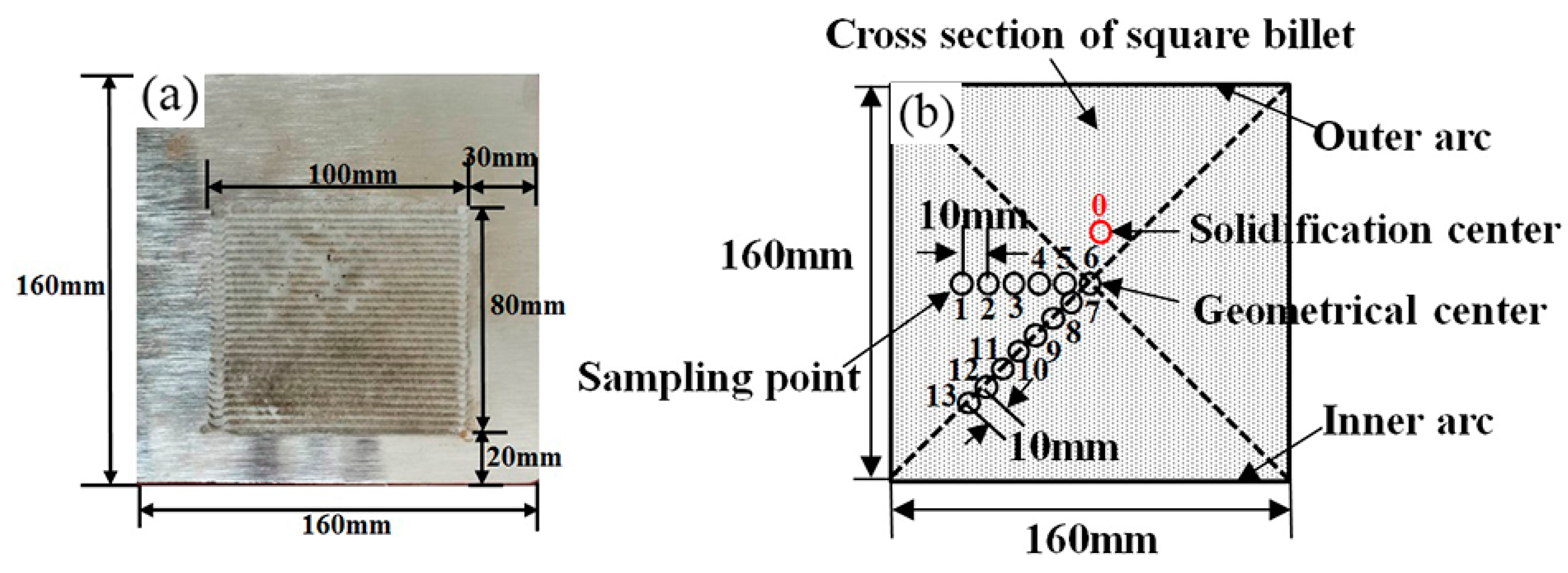
To assess the effects of final electromagnetic stirring parameters on central cross-sectional carbon concentration distribution of 70 high carbon steel, the plant trials with stirring parameters elaborately set were carried on a six strand billet continuous caster with a casting speed of 2.10 m/min, superheat value of 20 °C, and water ratio in secondary cooling of 1.5 L/kg. Then, several samples with a thickness of 25 mm were cut from billet. The current intensity of the F-EMS was set to 300 A, 350 A and 400 A and the frequency was 4 Hz, 6 Hz, 8 Hz and 12 Hz, respectively. With the frequency increasing to 12 Hz, the excited current intensity decreased dramatically due to the fixed power of electromagnetic stirrer, and only achieved 280 A. After polishing the cross section of the samples, an original position analyzer for metal (OPA-100, NCS Testing Technology Co., Ltd., Beijing, china) was conducted to detect the carbon concentration at the cross section, whose scanning area is shown in Figure 3a. The area ratios of different carbon concentrations were counted by Adobe Photoshop CS6 software, where the area ratio of some carbon concentration is the area of some carbon concentration to the scanning area. To reveal more accurately the concentration of solute element carbon in the stirring zone with different final electromagnetic stirring parameters, 13 spots were bored in the cross section along the radial center line and diagonal with a diameter of 5 mm drill, as shown in Figure 3b. The steel filings were analyzed with carbon-sulfur analyzer. The carbon segregation index is defined as C/C0, where C is the carbon concentration at some point (drilling test), C0 is the carbon concentration in liquid steel (tundish test). The typical chemical composition of 70 high carbon steel is shown in Table 2. The solidification structures of longitudinal sections of billet were revealed by macrostructure and defect erosion inspection methods.

3. Results and Discussion

3.1. Electromagnetic Forces of Final Electromagnetic Stirring (F-EMS) with Different Stirring Parameters

A rotating magnetic field passing through the molten steel will induce eddy currents which travel in the direction perpendicular to the magnetic field. The interaction between the internal magnetic field and the eddy currents will produce an electromagnetic force. The electromagnetic force, whose action is perpendicular to both the magnetic field and induced currents, will cause the stirring movement in the melt. Figure 4 and Figure 5 show the tangential electromagnetic forces on the center line and diagonal of the x–y plane at z = 0 mm (a), z = 112 mm (b), z = 224 mm (c) and z = 336 mm (d) under different stirring parameters. It can be seen that the electromagnetic forces on the center line and diagonal of the x–y plane at z = 112 mm and z = 336 mm are much larger than those of the x–y plane at z = 0 mm and z = 224 mm. With the current intensity and frequency increasing, the electromagnetic force on the center line of the x–y plane increases proportionally, as shown in Figure 4. Meanwhile, the electromagnetic force firstly increases and then decreases as the distance from billet edge increases, and obtains peak value near the edge of the billet. To F-EMS, the increasing frequency is much more important to add electromagnetic force than that of increasing current density. It can be concluded that the electromagnetic force of F-EMS could be effectively increased by adding stirring frequency. The current intensity of 400 A and frequency of 8 Hz, achieves the maximum electromagnetic force on the center line of the x–y plane at z = 112 mm among the 10 groups of electromagnetic stirring parameters, whose maximum electromagnetic force is 836 N/m3 and located at the position with 48 mm away from the edge of the billet, which is more liable to carry the enriched carbon element at the solid–liquid interface to the liquid core, followed by the current intensity of 350 A and frequency of 8 Hz and the current intensity of 280 A and frequency of 12 Hz. As the distance from the billet edge on the center line increases from 48 mm to 80 mm (liquid core zone), the electromagnetic force gradually decreases. The variation trends of the electromagnetic force on the diagonal of x–y plane under different stirring parameters are consistent with those on the center line. Nevertheless, some deviations exist between the electromagnetic force on the center line (F) and that on the diagonal (F′) in the liquid core zone. It can be observed from Figure 5 that the electromagnetic force near the diagonal center is the greatest and the current intensity of 280 A and frequency of 12 Hz obtain the maximum electromagnetic force in the liquid core zone of the x–y plane at z = 112 mm among the ten groups of electromagnetic stirring parameters, which is probably the benefit of accelerating mixture between the low-temperature liquid steel near the slurry–porous interface and the molten steel in the billet center.

3.2. Effect of F-EMS Parameters on Central Cross-Sectional Carbon Concentration Distribution of Square Billet

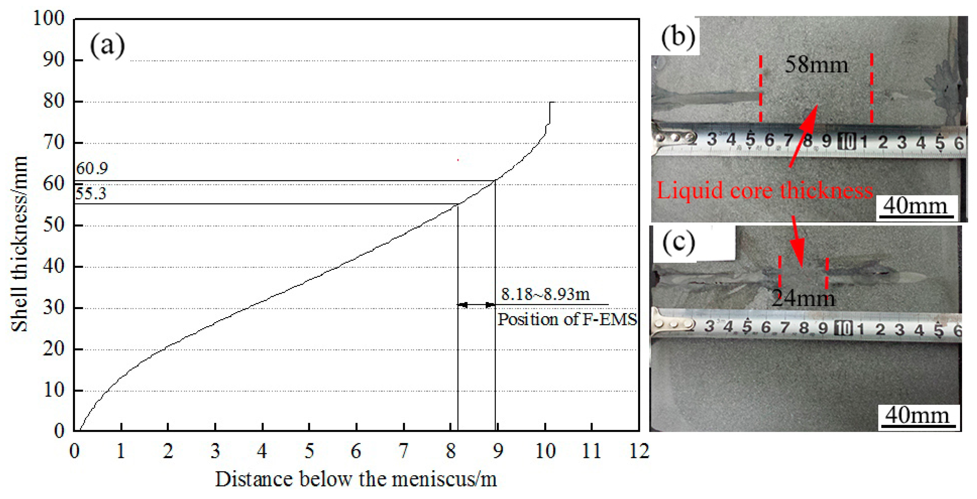
Figure 6 illustrates the simulated results of shell thickness, which are calculated by solidification and heat transfer model, and the morphologies of slab samples with steel nails. In the simulated results, the shell thickness at the F-EMS position is between 55.3 mm and 60.9 mm. As shown in experimental results, the shell thickness at the inlet and outlet of the stirrer is 58 mm and 24 mm, respectively. It can be concluded that the thickness data of the solidification shell in the simulated results is located within the range of the measured data in the experimental results. The mathematical model of solidification and heat transfer can predict the solidification behavior well. Li et al. [17] reported that the position where the solidification rate is 70% or so is suitable for the F-EMS and the solidification rate at the inlet of the stirrer is 72.5% in this work, which demonstrated that the F-EMS position is very reasonable to the actual second cooling condition of 70 steel.
Figure 7 and Figure 8 present the two-dimensional contour map and area ratio of different carbon concentration in the middle of the billet cross section with different stirring parameters, which are analyzed with OPA-100 and Adobe Photoshop CS6 software. It can be seen that the negative segregation close to the billet center has been already formed as shown in Figure 7a,c,h–j. It is attributed to the thermosolutal convection of the liquid phase and the sedimentation of depleted equiaxed grain in the secondary cooling zone. In order to analyze it conveniently, carbon concentration in excess of 0.78% and in lack of 0.62% are defined as carbon-rich and carbon-poor concentration, respectively. The carbon concentration in the range of 0.66%–0.74% is defined as carbon-medium concentration whose carbon concentration is close to the tundish carbon concentration. It is also seen that the area ratio of carbon-rich and carbon-poor concentration decreases obviously, and the area ratio of carbon-medium concentration increases apparently in the middle of billet cross section as F-EMS frequency increases from 4 Hz to 8 Hz and current intensity is 300 A, as shown in Figure 8a. Increasing the current intensity from 300 A to 350 A, and then to 400 A, the area ratio of carbon-medium concentration increases gradually, which were compared at the same frequency. Jiang and Zhu reported that the effect of F-EMS on center segregation is the competition between the decease of center temperature and the increase of liquid solute concentration [18]. Increasing the current and frequency to some extent will induce low-temperature liquid steel near the slurry–porous interface mixing better with elevated molten steel in the billet center. The strand center temperature drops quickly and the solidification rate will increase and, as a result, limit the transportation of rejected carbon element after electromagnetic stirring, which promotes the uniformity of carbon concentration in the middle of the billet cross section. As current intensity is 280 A and frequency is 12 Hz, the area ratios of carbon concentrations of 0.66 wt%, 0.70 wt% and 0.74 wt% reach 28.5%, 56.9% and 10.9%, respectively, and the predicted center carbon concentration could be reduced to 0.78% as shown in Figure 8d. This demonstrates that the billet achieves the most uniform carbon concentration in the middle of the cross section, compared to that with other stirring parameters. With the frequency increasing from 6 to 8 Hz, the transport of the liquid carbon element in the F-EMS zone may be the main factor, resulting in the increase of final center segregation. Figure 7i shows that the area ratio of carbon-rich and carbon-poor concentration is larger with higher frequency. Because the center segregation is controlled by the solidification rate at lower frequency and is affected by liquid solute transport in the F-EMS zone with higher frequency, the final billet center segregation decreases first and then turns to rise.

3.3. Effect of F-EMS Parameters on Carbon Segregation of Cross Section of Square Billet

The carbon segregation index in the middle of the billet cross section along the radial center line and diagonal with different stirring parameters is given in Figure 9. When the current intensity is 300 A and frequency is 4 Hz, the carbon segregation index at the solidification center and geometrical center of the billet are 1.23 and 1.21, respectively. Moreover, the carbon segregation indexes along the radial center line and diagonal from geometrical center to edge decrease obviously from 1.21 to 0.94, and from 1.21 to 0.89, respectively. It can also be observed from Figure 9a that the carbon segregation index at solidification and geometrical center of the billet firstly decreases and then increases simultaneously with stirring frequency increasing from 4 Hz to 8 Hz. Furthermore, the carbon segregation index of all sampling points is closer to 1.0 as frequency is 6 Hz, compared to the frequency being 4 Hz and 8 Hz. This indicates that the carbon concentration in the middle of billet cross section is more well-distributed with frequency of 6 Hz. As current intensity increases from 300 A to 350 A, and then to 400 A, the carbon segregation index at the sampling points of the cross section decreases gradually, compared at the same frequency, as shown in Figure 9a–c. Thus, it can be concluded that increasing the current intensity to 400 A and maintaining frequency at 6 Hz can effectively reduce center carbon segregation of the billet cross section of 70 steel. However, an excess of stirring intensity such as current intensity of 400 A and frequency of 8 Hz, is likely to further accelerate the transportation of the liquid steel enriched with the carbon element in the equiaxed porous zone to the liquid pool. Hence, it will lead to the increase of liquid carbon concentration and a higher carbon segregation index at solidification and the geometrical center as shown in Figure 9c. Although the drilling values close to the center point are a little lower than the original position analyzed, the original position analyzed and drilling results of central cross-sectional carbon concentration distribution show the same variation with F-EMS set at different stirring parameters, as shown in Figure 7 and Figure 9. The optimal F-EMS parameter to uniform the central cross-sectional carbon concentration and minimize the center carbon segregation of 70 steel billet has been obtained with current intensity of 280 A and frequency of 12 Hz. Under this stirring parameter, the carbon segregation indexes for all sampling points are in the range of 0.92–1.05, which is attributed to the fact that its stirring intensity is more suitable for decreasing the strand center temperature and increasing the solidification rate of billet. Therefore, the rejected solute element has limited time to transport after electromagnetic stirring, which promotes the reduction of center segregation.

3.4. Effect of F-EMS on Internal Quality of Square Billet

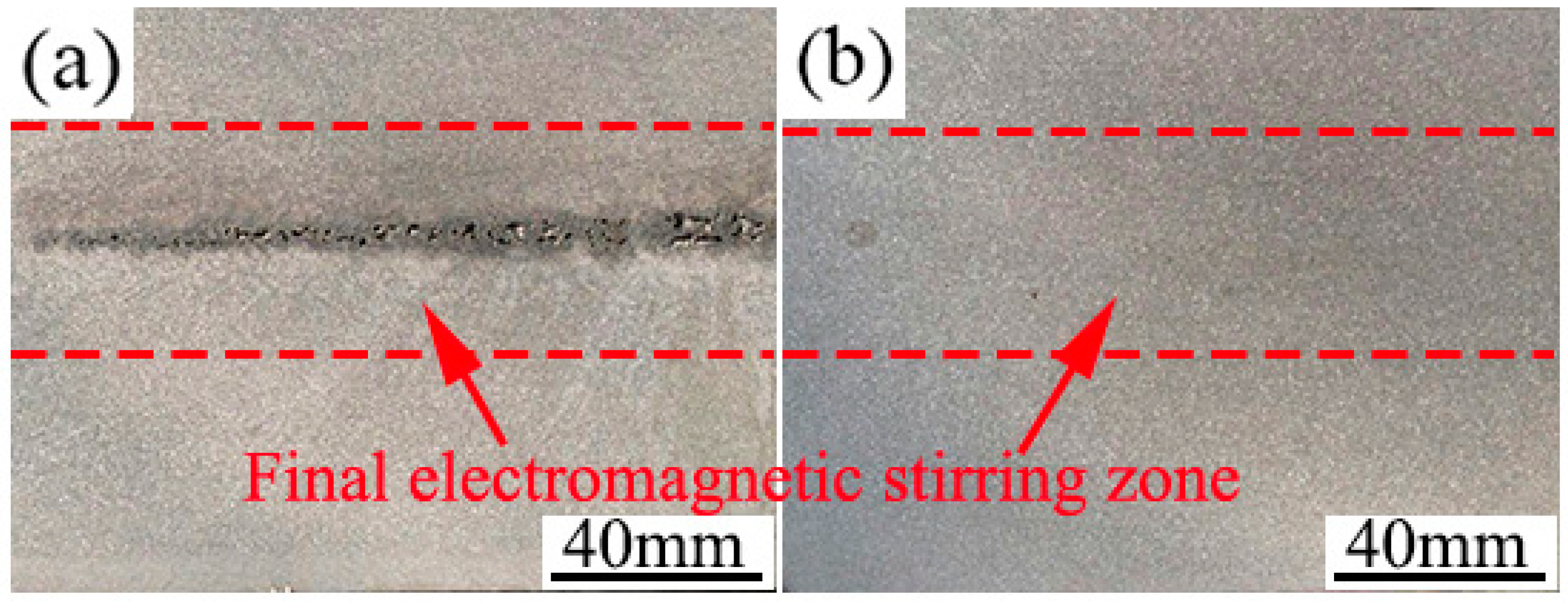
It is well known that porosities and shrinkage cavity occur in the central part of continuous casting blooms and billets [19,20]. Although there are good results in carbon segregation levels at a stirring current and frequency of 280 A and 12 Hz, respectively, further investigations have shown that the F-EMS has a significant impact on the other internal qualities of a square billet. Figure 10 shows the macroscopic structure of a longitudinal section at a current intensity of 280 A and frequency of 12 Hz, compared to a current of 300 A and frequency of 4 Hz. As seen in Figure 10a, at the billet centerline, where the last remaining portion of the liquid pool solidifies, a large area of shrinkage porosities has been formed. The central shrinkage porosity of the billet with current of 280 A and frequency of 12 Hz is less pronounced and more uniform in distribution, as shown in Figure 10b. Moreover, there exists a serious segregation defect such as center black spot in the etched macrograph with current of 300 A and frequency of 4 Hz. However, the segregation defect of the billet apparently subsides with a current of 280 A and frequency of 12 Hz, which illustrates that the current of 280 A and frequency of 12 Hz is the optimal F-EMS parameter to improve the segregation defect and internal quality of 70 steel billet.

4. Conclusions

The effect of final electromagnetic stirring parameters with current intensity increasing from 300 A to 400 A and frequency increasing from 4 Hz to 12 Hz, on the electromagnetic forces and carbon concentration distribution in the central cross section of 70 steel square billet has been studied. The results can be summarized as below:
(1)
With frequency increasing to 12 Hz, the current intensity can measure up to 280 A due to the fixed power of the electromagnetic stirrer.
(2)
The electromagnetic forces in the liquid zone of cross section at z = 112 mm and z = 336 mm are much larger than that at z = 0 mm and z = 224 mm. Along the center line of the liquid core zone, the electromagnetic force gradually decreases as the distance from the billet edge increases. The current intensity of 400 A and frequency of 8 Hz achieves the maximum electromagnetic force among the 10 groups of electromagnetic stirring parameters and is more liable to carry the enriched carbon element at the solid–liquid interface to the liquid core. Nevertheless, along the diagonal of the liquid core zone, the electromagnetic force near the diagonal center is the greatest and the current intensity of 280 A and frequency of 12 Hz obtains the maximum electromagnetic force.
(3)
The area ratio of carbon-medium concentration increases apparently in the middle of the billet cross section as the F-EMS current intensity and frequency increase to some extent. The optimal F-EMS parameter to make uniform the central cross-sectional carbon concentration and minimize the center carbon segregation of 70 steel billet has been obtained with a current intensity of 280 A and frequency of 12 Hz. Under this final electromagnetic stirring parameter, the area ratios of carbon concentrations of 0.66 wt%, 0.70 wt% and 0.74 wt% in the middle of the billet cross section are 28.5%, 56.9% and 10.9%, respectively. Moreover, the carbon segregation indexes for all the sampling points are in the range of 0.92–1.05.

Author Contributions

Software, Y.W. and W.Z.; investigation, M.L. and L.C.; writing—original draft preparation, Y.W.; supervision, J.L.; funding acquisition, H.P.

Funding

This research was funded by the State Key Laboratory of Refractories and Metallurgy (Wuhan University of Science and Technology), grant number G201902 and the National Natural Science Foundation of China, grant number 51604004.

Acknowledgments

The authors are grateful for the support of the the State Key Laboratory of Refractories and Metallurgy (Wuhan University of Science and Technology)(G201902) and National Natural Science Foundation of China (51604004).

Conflicts of Interest

The authors declare no conflict of interest.

References

  1. Beckermann, C. Modelling of macrosegregation: Applications and future needs. Int. Mater. Rev. 2002, 47, 243–261. [Google Scholar] [CrossRef]
  2. Eskin, D.G.; Nadella, R.; Katgerman, L. Effect of different grain structures on centerline macrosegregation during direct-chill casting. Acta Mater. 2008, 56, 1358–1365. [Google Scholar] [CrossRef] [Green Version]
  3. Raihle, C.M.; Fredriksson, H. On the formation of pipes and centerline segregates in continuously cast billets. Metall. Mater. Trans. B 1994, 25, 123–133. [Google Scholar] [CrossRef]
  4. Yamazaki, M.; Natsume, Y.; Harada, H.; Ohsasa, K. Numerical simulation of solidification structure formation during continuous casting in Fe–0.7 mass% C alloy using cellular automaton method. ISIJ Int. 2006, 46, 903–908. [Google Scholar] [CrossRef]
  5. Power, P.; Yalamanchili, B.; Centa, T.; Lanham, D.; Boudreaux, T.; Boucier, T.; Hanchey, J. Importance of superheat and chemistry control for high carbon (1080) prestressed concrete grade steel. In Proceedings of the International Symposium on Near-Net-Shape Casting in the Minimills, Vancouver, BC, Canada, 19–23 August 1995; pp. 123–133. [Google Scholar]
  6. Stercken, K. Aspects of center segregation in high-carbon wire rod rolled from continuously cast billets. In Proceedings of the International Symposium on Near-Net-Shape Casting in the Minimills, Vancouver, BC, Canada, 19–23 August 1995; pp. 163–177. [Google Scholar]
  7. Ghosh, A. Principles of Secondary Processing and Casting of Liquid Steel; Raju Primlani: New Delhi, India, 1990. [Google Scholar]
  8. Sung, P.K.; Poirier, D.R.; Yalamanchili, B.; Geiger, G.H. Segregation of carbon and manganese in continuously cast high carbon steel for wire rod. Ironmak. Steelmak. 1990, 17, 424. [Google Scholar]
  9. Thome, R.; Harste, K. Principles of billet soft-reduction and consequences for continuous casting. ISIJ Int. 2006, 46, 1839–1844. [Google Scholar] [CrossRef]
  10. Ludlow, V.; Normanton, A.; Anderson, A.; Thiele, M.; Ciriza, J.; Laraudogoitia, J.; van der Knoop, W. Strategy to minimise central segregation in high carbon steel grades during billet casting. Ironmak. Steelmak. 2005, 32, 68–74. [Google Scholar] [CrossRef]
  11. Oh, K.S.; Chang, Y.W. Macrosegregation behavior in continuously cast high carbon steel blooms and billets at the final stage of solidification in combination stirring. ISIJ Int. 1995, 35, 866–875. [Google Scholar] [CrossRef]
  12. Du, W.-D.; Wang, K.; Song, C.-J.; Li, H.-G.; Jiang, M.-W.; Zhai, Q.-J.; Zhao, P. Effect of special combined electromagnetic stirring mode on macrosegregation of high strength spring steel blooms. Ironmak. Steelmak. 2008, 35, 153–156. [Google Scholar] [CrossRef]
  13. Suzuki, K.; Shinsho, Y.; Murata, K.; Nakanishi, K.; Kodama, M. Hot model experiments on electromagnetic stirring at about crater end of continuously cast bloom. Trans. Iron Steel Inst. Jpn. 1984, 24, 940–949. [Google Scholar] [CrossRef]
  14. Sun, H.; Zhang, J. Study on the macrosegregation behavior for the bloom continuous casting: Model development and validation. Metall. Mater. Trans. B 2014, 45, 1133–1149. [Google Scholar] [CrossRef]
  15. Luo, S.; Piao, F.-y.; Jiang, D.-b.; Wang, W.-l.; Zhu, M.-y. Numerical simulation and experimental study of F-EMS for continuously cast billet of high carbon steel. J. Iron. Steel Res. Int. 2014, 21, 51–55. [Google Scholar] [CrossRef]
  16. Jiang, D.; Zhu, M. Center segregation with final electromagnetic stirring in billet continuous casting process. Metall. Mater. Trans. B 2017, 48, 444–455. [Google Scholar] [CrossRef]
  17. Li, J.; Wang, B.; Ma, Y.; Cui, J. Effect of complex electromagnetic stirring on inner quality of high carbon steel bloom. Mater. Sci. Eng. A 2006, 425, 201–204. [Google Scholar] [CrossRef]
  18. Jiang, D.; Zhu, M. Solidification structure and macrosegregation of billet continuous casting process with dual electromagnetic stirrings in mold and final stage of solidification: A numerical study. Metall. Mater. Trans. B 2016, 47, 3446–3458. [Google Scholar] [CrossRef]
  19. Flemings, M.C. Our understanding of macrosegregation: Past and present. ISIJ Int. 2000, 40, 833–841. [Google Scholar] [CrossRef]
  20. Krauss, G. Solidification, segregation, and banding in carbon and alloy steels. Metall. Mater. Trans. B 2003, 34, 781–792. [Google Scholar] [CrossRef]
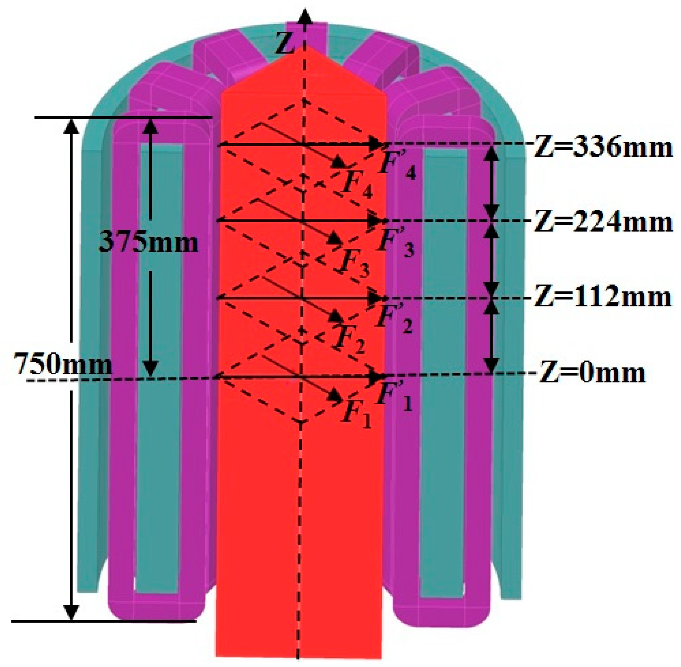
Figure 1. Geometric model of final electromagnetic stirring (F-EMS) device and the computational domain of electromagnetic forces.
Metals 09 00665 g001
Figure 2. Diagrammatic sketch of nail-shooting experiments and final electromagnetic stirring.
Metals 09 00665 g002
Figure 3. Schematic diagrams of billet scanning area detected by original position analyzer (a) and drilling positions (b).
Metals 09 00665 g003
Figure 4. The electromagnetic forces on the center line of the x–y plane at z = 0mm (a), z = 112mm (b), z = 224 mm (c) and z = 336 mm (d), respectively.
Metals 09 00665 g004aMetals 09 00665 g004b
Figure 5. The electromagnetic forces on the center diagonal of the x–y plane at z = 0mm (a), z = 112 mm (b), z = 224 mm (c) and z = 336 mm (d), respectively.
Metals 09 00665 g005aMetals 09 00665 g005b
Figure 6. The simulated results of fraction solid (a) and the morphologies of slab samples with steel nails at the inlet (b) and outlet (c) of the stirrer.
Metals 09 00665 g006
Figure 7. The two-dimensional contour map of different carbon concentrations in the middle of the billet cross section with different stirring parameters: (a) 300 A, 4 Hz; (b) 300 A, 6 Hz; (c) 300 A, 8 Hz; (d) 350 A, 4 Hz; (e) 350 A, 6 Hz; (f) 350 A, 8 Hz; (g) 400 A, 4 Hz; (h) 400 A, 6 Hz; (i) 400 A, 8 Hz; (j) 280 A, 12 Hz.
Metals 09 00665 g007
Figure 8. The area ratio of different carbon concentration in the middle of billet cross section with different stirring parameters: (a) 300 A, 4–8 Hz; (b) 350 A, 4–8 Hz; (c) 400 A, 4–8 Hz; (d) 280 A, 12 Hz.
Metals 09 00665 g008aMetals 09 00665 g008b
Figure 9. The carbon segregation index in the middle of billet cross section along the radial center line and diagonal with different stirring parameters: (a) 300 A, 4–8 Hz; (b) 350 A, 4–8 Hz; (c) 400 A, 4–8 Hz; (d) 280 A, 12 Hz.
Metals 09 00665 g009aMetals 09 00665 g009b
Figure 10. The macroscopic structure of longitudinal section with current intensity of 300 A and frequency of 4 Hz (a), and current intensity of 280 A and frequency of 12 Hz (b), respectively.
Metals 09 00665 g010
Table 1. Physical properties and process parameters for simulation.
ItemValue (Unit)
Number of turns150
Current phase and phase difference of the magnetic stirring coil3 and 120°
Coil cross-sectional area4.8 × 10−3(m2)
Density of the liquid steel7000 (kg/m3)
Electrical resistivity of 70 steel1.6 × 10−6 (Ω·m)
Density of liquid steel7000 (kg/m3)
Viscosity of liquid steel5.5 × 10−3 (kg/m/s)
Electrical conductance of liquid steel7.14 × 106 (S/m)
Electrical conductance of air8.86 × 10−12 (S/m)
Electrical conductance of slab shell1.0 × 106 (S/m)
Electrical conductance of stainless steel1.33 × 106 (S/m)
Electrical conductance of iron core0 (S/m)
Relative magnetic permeability of liquid steel1
Relative magnetic permeability of air1
Relative magnetic permeability of slab shell1
Relative magnetic permeability of stainless steel1
Relative magnetic permeability of iron core1000
Table 2. Typical chemical composition of 70 steel (wt.%).
CSiMnSPAlsOtol
0.700.200.600.0060.0190.0010.0023