Article

Microstructures, Tensile Properties and Creep Characteristics of as-Extruded AZ91 Magnesium Alloy Containing Si, Ca and Rare Earth Elements

1
Zhejiang Key Laboratory for Protection Technology of High-Rise Operation, Zhejiang Huadian Equipment Testing Institute Co. LTD, Hangzhou 310015, China
2
State Key Laboratory of Rare Earth Resource Utilization, Changchun Institute of Applied Chemistry, CAS, Changchun 130022, China
3
College of Materials Science and Engineering, Harbin Engineering University, Harbin 150001, China
4
Roll Forging Research Institute, Jilin University, Changchun 130025, China
5
Heavy Machinery Engineering Research Center of the Ministry of Education, Taiyuan University of Science and Technology, Taiyuan 030024, China
*
Authors to whom correspondence should be addressed.
Metals 2019, 9(9), 954; https://doi.org/10.3390/met9090954
Submission received: 19 June 2019 / Revised: 2 August 2019 / Accepted: 20 August 2019 / Published: 30 August 2019
(This article belongs to the Special Issue Alloy Design)

Abstract

:
Wrought AZ (Mg–Al–Zn) series alloys have attracted lots of researches, due to low cost, high strength and good formability. Few researches focus on creep characteristics of wrought AZ series alloys, which might be of significance to extensive use of low-cost wrought Mg–Al based alloy at elevated temperature. The microstructures, tensile properties and creep characteristics of as-extruded Mg-9Al-Zn-0.5RE-0.5Ca-0.5Si (wt.%, named AZXSE91000) alloy were investigated by optical microscopy (OM), scanning electron microscopy (SEM), X-ray diffractometer (XRD), TEM (transmission electron microscopy), tensile tests and tensile creep tests (40–100 MPa, 125–150 °C). The as-extruded AZXSE91000 alloy exhibited good tensile strength both at room temperature and elevated temperature. The co-addition of Si, Ca and rare earth elements can improve the heat resistance of as-extruded AZ91 alloy resulting from fragmented heat-resistant particles hindering grain boundaries sliding. The steady creep rates of as-extruded AZXSE91000 alloy can be comparable with that of as-cast AZ91 alloy under similar experimental conditions. Dislocation climbing and grain boundary slip should dominantly contribute to the creep of as-extruded AZXSE91000 alloy. The asymmetric discontinuous precipitation in crept samples revealed that diffusion played an unneglected role during the creep process.

1. Introduction

Magnesium alloys are new light-weight metal structural materials [1,2,3,4]. Mg–Al–Zn (AZ series) alloys are among the most popular magnesium alloys and widely used for commercial applications, owing to their low cost, excellent room temperature strength, good die castability and favorable corrosion resistance [5]. Although a majority of AZ series alloys are applied as die-cast parts [6], the wrought AZ series alloys have attracted lots of researches [7,8,9], due to high strength, high ductility and good formability of wrought Mg alloys [10,11]. For example, recently, the researches on uniaxial compression deformation behavior [12] and reducing of edge cracks by multi-cross rolling of AZ31B alloy [13] were carried out. Zeng et al. obtained a high strength as-extruded AZ31 alloy via suppressing intergranular deformation [14].
The Mg17Al12 phase is the main eutectic compound in the AZ series alloys, whose softening results in poor mechanical properties of AZ series alloys above 120 °C [15]. Former research revealed that existence of the Mg17Al12 phase promoted migration and sliding of grain boundaries during the creep test, leading to poor creep resistance of AZ series alloys, both distributing at grain boundaries and discontinuously precipitating in grains [16]. There are two methods to improve the creep resistance of AZ series alloys, i.e., restraining the formation of the Mg17Al12 phase and introducing thermally stable secondary phases [5]. Co-addition of Si, Ca and rare earth elements into AZ series alloys can introduce heat-resistant secondary phases, such as Al2Ca, Al2RE, Al11RE3, CaMgSi and Mg2Si. Meanwhile, it can suppress the formation of Mg17Al12 phase [15,17,18,19]. Former work from the authors revealed that the coarse Mg2Si and CaMgSi could be fragmented into finer dispersed particles after hot extrusion in AZXSE91100 alloy (Mg-9Al-Zn-1Ca-0.5Si-0.1La-0.1Ce, wt.%), which can improve heat resistance of the as-extruded alloy [19].
Lots of researches on creep characteristics of as-cast Mg–Al based alloys were carried out [5,20,21], while few researches focused on wrought Mg–Al based alloys. According to former research [20], dislocation climbing and grain boundary sliding were the dominant creep mechanisms for as-cast Mg–Al based alloys. The further addition of Si, rare earth elements or alkaline earth elements could enhance creep resistance of as-cast Mg–Al based alloys, which was attributed to heat-resistant intermetallic particles hindering grain boundaries sliding and dislocation slip, or to strengthening Mg matrix via solid solution and/or precipitation hardening [20].
In this work, based on the as-extruded AZXSE91100 alloy, the contents of Si, Ca and rare earth element have been further adjusted slightly, in order to obtain optimal alloying composition. Four similar as-extruded alloys (Mg-9Al-Zn-0.5RE-Si, Mg-9Al-Zn-0.5RE-0.5Ca-Si, Mg-9Al-Zn-0.5RE-0.5Ca, Mg-9Al-Zn-0.5RE-0.5Ca-0.5Si, wt.%) have been designed and researched, among which the as-extruded Mg-9Al-Zn-0.5RE-0.5Ca-0.5Si (wt.%) alloy exhibited the best mechanical properties both at room and elevated temperature (only the analysis results of the fourth alloy will be presented in this paper). In fact, the coarse Mg17Al12 phase in the as-cast Mg–Al based alloys can dissolve into the Mg matrix or be fragmented into small pieces after T4 treatment following hot extrusion, which may be good for the improvement of creep resistance owing to content decreasing and morphology changing of Mg17Al12 phase. The coarse Mg2Si, CaMgSi, Al2RE and Al11RE3 phase could be fragmented into finer dispersed particles after hot extrusion in Mg-9Al-Zn-0.5RE-0.5Ca-0.5Si (wt.%, named AZXSE91000) alloy, which may influence the creep characteristics of as-extruded AZXSE91000 alloy via hindering grain boundaries sliding and dislocation slip. Therefore, this work focuses on researching the tensile creep characteristics of as-extruded AZXSE91000 alloy, which may be of significance to extensive use of a low-cost wrought Mg–Al based alloy at elevated temperature.

2. Materials and Methods

2.1. Casting

The raw materials of the as-cast AZXSE91000 alloy were commercial pure magnesium, pure aluminum, pure zinc, Mg-20Si (wt.%), Mg-20Ca (wt.%) and Mg-20MM (wt.%, MM was the mixed rare earth element containing La and Ce) master alloys. At first, pure Mg was melt in an electric resistance furnace under protective atmosphere consisting of CO2 and SF6. Then pure Al, pure Zn and the master alloys were added into the furnace with maintaining a furnace temperature at 760 °C for at least 30 min after all the ingots were melted. The molten metal was stirred for ~3 min, and sat quietly for ~30 min. At last, the molten metal was poured into a cylindrical steel mold (Φ 90 mm × ~500 mm) with a circulating water cooling system, before which the impurities were excluded from the molten metal. The chemical composition of as-cast AZXSE91000 alloy was analyzed by inductively coupled plasma (ICP), as shown in Table 1. The powder sample for ICP was taken from different positions of as-cast ingots.

2.2. Hot Extrusion

At first, the as-cast AZXSE91000 alloy was solution treated at 420 °C for 20 h (T4). Then the cylindrical ingot was machined into a cylinder with a diameter of 82 mm and length of 100 mm. The solution-treated AZXSE91000 alloy cylinder was be extruded as a bar with diameter of 15 mm at 360 °C with speed of ~1.5 mm/s, before which the cylinder and extrusion die were heated to 360 °C for at least 90 min.

2.3. Tensile Creep Test

The tensile creep test of as-extruded AZXSE91000 alloy was carried out by the CRIMS RDL50 creep testing machine with a temperature of 125–150 °C and stress of 40–100 MPa for 50 h. The shape and size of the tensile creep rod-like sample is shown in Figure 1a, and the tensile direction of sample parallels to the extrusion direction of the bar.
The microstructures of the as-cast and as-extruded samples were analyzed by optical microscopy (OM; Olympus-GX71, Tokyo, Japan), SEM (Hitachi, S-4800 SEM, Tokyo, Japan) equipped with an energy dispersive spectrometer (EDS, Oxford, UK) and an EDAX/TSL electron back scattered diffraction (EBSD, EDAX, Inc., New York, NY, USA). The operating voltage and current for SEM and EDS were 10 kV/10 μA and 20 kV/15 μA respectively. The sample for EBSD was cut from the as-extruded bar with 8 mm × 5 mm × 4 mm whose observed surface (8 mm × 5 mm) was parallel to the extrusion direction and passed the axis of the as-extruded bar. The observed surface of the sample was machine polished with 0.05 μm Al2O3 suspensions at first, then was electrochemically polished (commercial ACII electrolyte, 20 V/0.1 A at ~−20 °C). The XRD tests were implemented by an 18 kW type X-ray diffractometer (Rigaku D/max 2500 PC X-ray Diffractometer, Tokyo, Japan) operated at 40 kV and 40 mA. The tensile experiments of as-extruded sample were implemented by a MTS810 material test machine (MTS, WA, USA) with a speed of 1 mm/min, at room temperature, 150 °C and 200 °C respectively. Tensile samples were flat tensile specimens with a gauge length of 20 mm and cross-section of 3 mm × 4 mm, and the tensile direction paralleled to the extrusion direction, as shown in Figure 1b. In order to ensure repeatability of the datum, five samples were tested for the same condition. The nano-scale analysis of tensile sample was examined by TEM (JEM-2100F, Tokyo, Japan) operating at 200 kV. The TEM sample was taken from the gauge length part of the tensile sample, with the foil surface paralleling to the tensile direction. The foil was polished to 20 μm thick, then was machined by an ion milling instrument (Ion milling system Leica EM RES101, Wetzlar, Germany).

3. Results

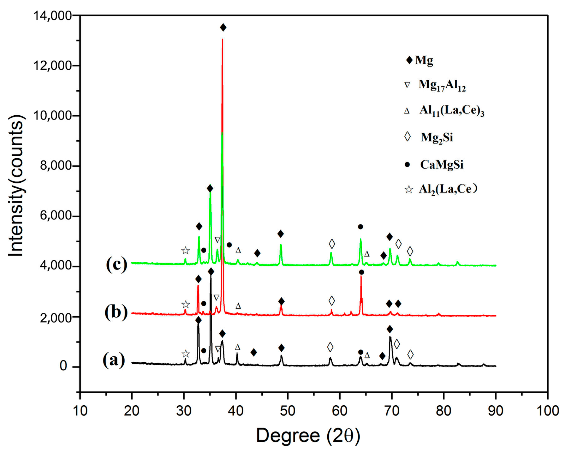
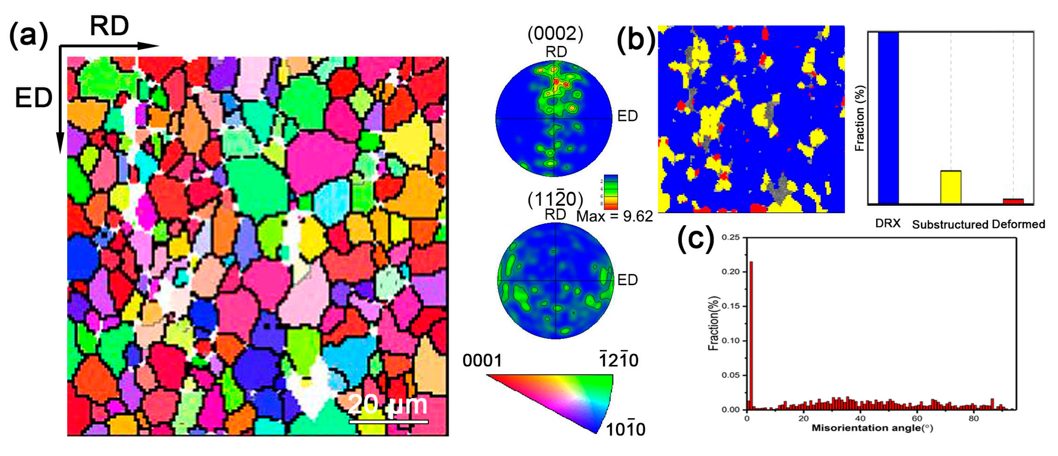
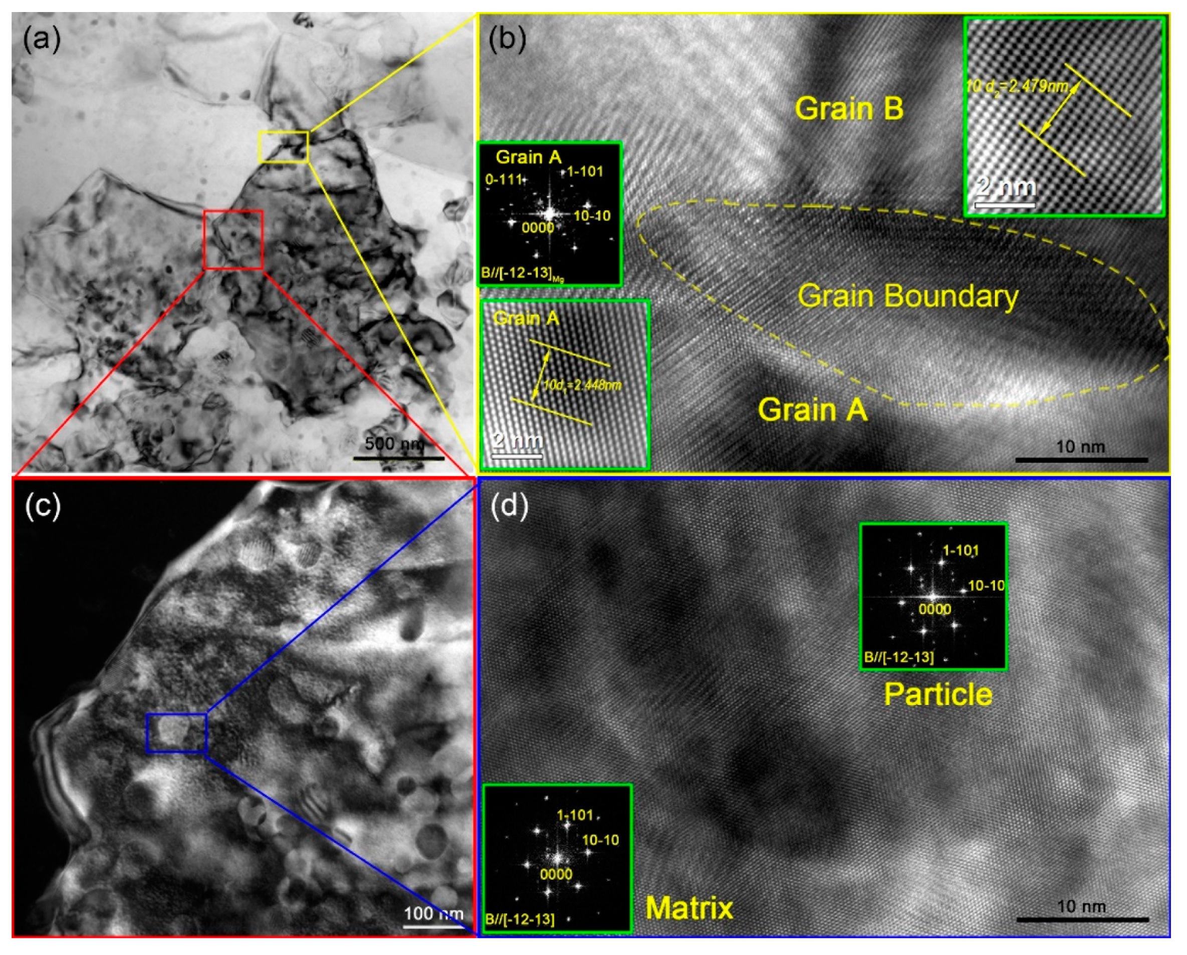
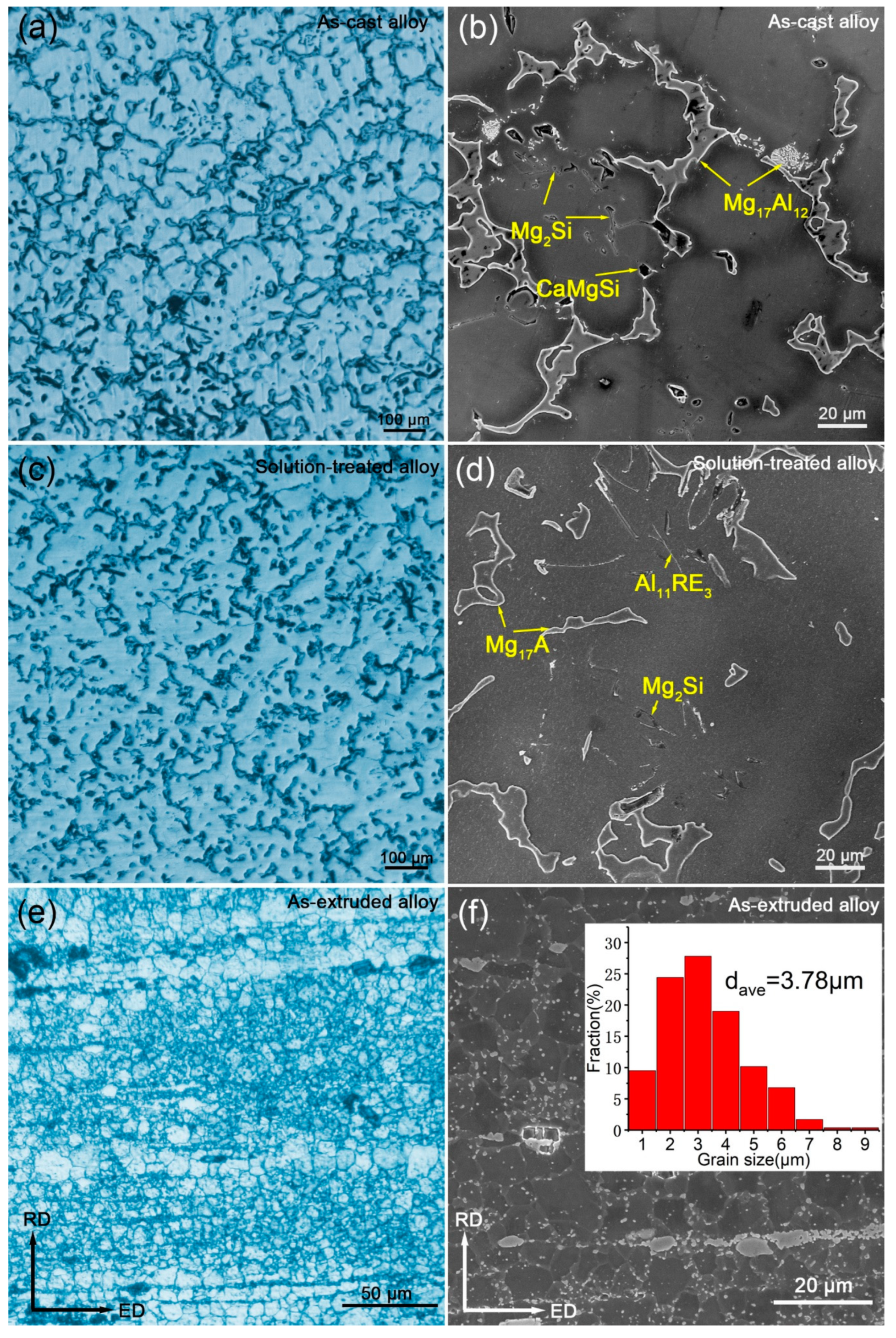
3.1. Microstructures

Figure 2a–c shows the XRD patterns of the as-cast, solution-treated and as-extruded AZXSE91000 alloy respectively. It could be concluded that the as-cast, solution-treated and as-extruded AZXSE91000 alloy all contain the α-Mg matrix and intermetallic compounds, i.e., Mg17Al12, Al11RE3, Mg2Si and Al2RE. Comparing with the XRD patterns of AZXSE91100 alloy [19], the minor peaks near 30° were more remarkable in Figure 2a–c. In fact, the TEM analysis of as-extruded AZXSE91100 alloy (as shown in Figure 8 of ref. 19) indicated existence of the Al2RE phase, while low relative content of this phase led to a weak display in the XRD patterns. The content of La/Ce in the AZXSE91000 alloy (0.51 wt.%) was higher than that in AZXSE91100 alloy (0.24 wt.%), therefore the content of Al2RE phase was higher.
Figure 3a–f shows the OM and SEM images of the as-cast, solution-treated and as-extruded AZXSE91000. It could be observed that the island-shaped Mg17Al12 phase partially dissolved in the Mg matrix and contents and morphologies of the other intermetallic compounds were almost unchanged after 420 °C/20 h solution treatment, which agreed with the results of XRD. The microstructure of the as-extruded alloy consisted of fine equiaxed grain and massive broken intermetallic compounds distributing along extrusion bands. The grain size distribution of the as-extruded alloy is presented in the top right corner in Figure 3f, and average grain size of the as-extruded alloy was 3.78 μm, approaching the grain size of the as-extruded AZXSE91100 alloy (~3.0 μm).
Figure 4a shows the EBSD IPF (inverse pole figure) map and pole figures of the as-extruded AZXSE91000 alloy, which indicates that strong basal texture existed in the as-extruded alloy. Figure 4b shows the recrystallized grains distribution map and the histogram of recrystallization statistics of the as-extruded alloy. It could be concluded that ~81.6% of the area in the as-extruded alloy was the DRXed region, and only ~2.6% of the area was the deformed region. Figure 4c shows the histogram of misorientation angle distribution. A significant number of substructured grains existed in the as-extruded alloy consistent with the result in Figure 4c, in which a remarkable fraction of low angle grain boundary (LAGBs, ≤15°) reached ~30%.

3.2. Tensile Properties

Figure 5 shows the tensile engineering stress–strain curves of the as-extruded AZXSE91000 alloy at room temperature, 150 °C and 200 °C. The strength of the alloy decreased with temperature increasing, while the elongation increased. A comparative exhibition about the tensile properties of the as-extruded AZXSE91000 alloy and AZXSE91100 alloy has been presented in Table 2. It could be concluded that the yield strength (YS) and ultimate tensile strength (UTS) of the as-extruded AZXSE91000 alloy were higher than those of the as-extruded AZXSE91100 alloy at room temperature, while the situation of elongation was opposite. The grain size and texture should be the main factors to influence the strength of fine-grain as-extruded alloys, which have similar chemical compositions. According to the results of the grain statistics, the two as-extruded alloys had approximately equal grain sizes, therefore, the stronger basal texture might contribute to the improvement of yield strength of the as-extruded AZXSE91000 alloy at room temperature. Besides, the type and intensity of the texture can affect the Hall-Petch relationship, which also can influence the strength of the wrought Mg alloy [22,23,24].
Figure 6a shows a bright field TEM micrograph of the tensile sample of the as-extruded AZXSE91000 alloy at 200 °C. Several DRXed (dynamic recrystallization) grains could be observed, and their diameters ranged from 500 nm to 1 μm. Figure 6b shows the HRTEM (high resolution transmission electron microscopy) micrograph corresponding to the yellow rectangle zone in Figure 6a. A high angle DRXed grain boundary could be observed in Figure 6b. The left insets in Figure 6b were enlarged in the HRTEM image and FFT (fast Fourier transform) pattern of grain A, which reveals the electron beam parallels [ 1 2 ¯ 1 3 ¯ ] α - Mg direction of the Mg matrix. The inset at the top right corner was enlarged in the HRTEM image corresponding to grain B. By calculation, the interplanar spacing of d2 was 0.2479 nm, which approximates to the interplanar spacing of the { 10 1 ¯ 1 } α - Mg lattice plane of the Mg matrix, therefore, the lattice plane should be { 10 1 ¯ 1 } α - Mg .
Lots of nano-scale particles can be observed in Figure 6c, which is the enlarged dark field TEM micrograph corresponding to the red rectangle zone in Figure 6a. Further analysis via HRTEM is presented in Figure 6d. The FFT patterns of the Mg matrix and particle indicate the nano-scale particle had the same crystal structure with the Mg matrix, therefore, the nano-scale particles might be Guinier Preston (G.P.) zone forming in the process of hot extrusion or the tensile test at an elevated temperature.

3.3. Tensile Creep Characteristics

Figure 7 shows the creep curves and corresponding creep rate-time curves of the as-extruded AZXSE91000 alloy at 125–150 °C, 40–100 MPa. Under all the experimental conditions, no fracture happened for all the samples within 50 h. It could be observed that the creep curves contained two stages, namely the deceleration creep stage and the steady state creep stage. As is seen in Figure 7a,c, with the creep stress increasing, the strain of tensile creep sample increased obviously within 50 h, especially when the stress increased from 80 to 100 MPa. It could be seen from the creep rate-time curves in Figure 7b,d that the steady state creep rate of the sample increased with stress increasing. The creep experimental results of the as-extruded AZXSE91000 alloy at 125–150 °C and under a stress of 40–100 MPa have been presented in Table 3. It could be concluded that the creep strain and steady state creep rate increased obviously with temperature increasing when the stress maintained constant.
As is well known that creep deformation consists of three stages, i.e., primary creep, steady state creep and tertiary creep. While steady state creep is the most important process drawing more attention. In a general way, two variables can roughly estimate the dominant creep mechanism, i.e., creep stress exponent n and activation energy Q c [11]. In the steady state creep stage, the relationship between the creep rate and stress and temperature can be described by the following relationship [26,27,28],
ε ˙ = A σ n exp ( Q c R T ) ,
where ε ˙ presents the steady-state creep rate, A is a material-dependent constant, σ is the applied stress, n is the creep stress exponent, Q c is the creep activation energy, R is the gas constant and T is the creep temperature. Take the logarithm on both sides of Formula (1), the following equation can be obtained,
ln ε ˙ = n ln σ + ln A Q c R T .
In Equation (2), for a specific material, when the temperature is constant, ln A Q c R T is also constant, so the experimentally measured substituting into the formula. The value of n can be obtained by drawing the ln ε ˙ ln σ line and taking the slope value (as shown in Figure 8a). The value of Q c can be obtained by drawing the ln ε ˙ 1 / T line and taking the slope value (as shown in Figure 8b).
It could be seen that creep stress exponent n increased slightly with creep test temperature increasing. In general, when creep stress exponent n = 1, the creep behavior of the Mg alloy is considered to be mainly affected by diffusion, which generally occurs under conditions of higher temperature and lower stress, including Coble creep (grain boundary diffusion) and N–H creep; when the creep stress exponent n = 2–3, the corresponding main creep mechanism is the grain boundary slip and when the creep stress exponent n = 3–7, the corresponding main creep mechanism is the dislocation creep, which generally occurs under low temperature and high stress conditions [20,29,30,31]. In this paper, the creep stress exponent n was 3.0 and 3.3 at a temperature of 125 °C and 150 °C respectively, under a stress of 40–100 MPa. Although the values of the creep stress exponent n were between 3–7, the values of n also were close to 2–3. Therefore, the grain boundary slip and dislocation motion might be the main creep mechanisms under this condition for the as-extruded AZXSE91000 alloy.
Creep activation energy Q c is another important indicator to reveal the creep mechanism. Figure 8b shows the creep activation energy of the as-extruded AZXSE91000 alloy at 125–150 °C, under a stress of 40, 60, 80 and 100 MPa. The creep activation energy ranged from 150 to 190 kJ/mol within the stress range of 40–100 MPa.
The activation energy of grain boundary diffusion of magnesium alloy is about 92 kJ/mol [29,30,32], the activation energy of self-diffusion is about 135 kJ/mol [29,30,32] and the activation energy of dislocation climbing is about 126 kJ/mol. The activation energy of the as-extruded AZXSE91000 alloy at 125–150 °C, 40–100 MPa was significantly higher than the above values, indicating that grain boundary slip, dislocation climbing and lattice self-diffusion occurred in the process of the alloy under this condition.
Based on the above discussion and the values of the creep activation energy Q c and creep stress exponent n of the as-extruded AZXSE91000 alloy, value of n was about 3 in the range of 125–150 °C, 40–100 MPa, and it is believed that the creep mechanism of the alloy under this condition is dominated by the dislocation motion and grain boundary slip. Although the creep activation energy of the alloy was higher than the dislocation cross-slip activation energy (100 kJ/mol), the creep test temperature was relatively low, and the non-basal slip starting temperature of the magnesium alloy were generally around 225 °C. It could be concluded that cross-slip might contribute to creep deformation of the as-extruded AZXSE91000 alloy under the condition of 125–150 °C, 40–100 MPa, but it was not the main mechanism of the dislocation creep.

4. Discussion

The last column in Table 3 shows a steady creep rate of the as-cast AZ91 alloy at 150 °C and 50 MPa was 5.0 × 10⁻⁸ s−1 [25]. Comparing with the as-cast AZ91 alloy, the steady creep rates of the as-extruded AZXSE91000 alloy were comparable with that of the as-cast AZ91 alloy under similar experimental condition, whose values were 2.6 × 10⁻⁸ s−1 and 9.3 × 10⁻⁸ s−1 at 150 °C/40 MPa and 150 °C/60 MPa respectively. In other words, the creep resistance of the as-extruded AZXSE91000 alloy was comparable with that of the as-cast AZ91 alloy at 150 °C/40–60 MPa. Generally, the grain size of the as-cast AZ91 alloy sharply decreased after hot extrusion with a high extruded ratio of about 30:1, following heat resistance or creep resistance deteriorating owing to grain boundary increasing. The good creep resisrance of the as-extruded AZXSE91000 alloy should be attributed to co-addition of Si, Ca and RE. The fragmented heat-resistant intermetallics, such as Mg2Si, Al2RE, Al11RE3 and CaMgSi, distributed at grain boundaries, which could hinder the grain boundary slip.
Figure 9 shows typical SEM microstructures of crept samples at temperature of 125–150 °C, under a stress of 40–100 MPa. Obvious elongation of grains along the tensile creep direction can be observed in Figure 9, which indicates the grain boundary slip occurred during the creep test process. Besides, more and more discontinuous precipitates could be observed with temperature and stress increasing, which originated from the grain boundaries then spread to the grain interior. Differing from lots of PFZs (precipitation free zones) distributing at the grain boundary observed in crept Mg–RE samples [33,34], the PFZs of the crept as-extruded AZXSE91000 alloy were in the grain interior. As is well known that precipitation can be induced by heat treatment, i.e., isothermal aging. While the exerted stress can observably affect the precipitation behavior [33,35]. According to Nabbaro–Herring diffusion theory, the exerted stress can influence the vacancy diffusion behaviour around grain boundaries, the vacancy tend to concentrate in the grain boundary in tension [35]. The concentration gradient can drive a flow of vacancies from the boundary in compression to the boundary in tension, corresponding to a flow of atoms in the opposite form [33], as shown in Figure 10. Comparing with former research from Wang et. al. [33], the diffusion coefficient of the solute atom Al was much higher than Gd and Y, thus the Al atoms migrated to the grain boundary in compression substituting for Mg atoms. This would result in a solute concentration zone near the grain boundary in compression. Therefore, the discontinuous precipitation near the grain boundary in compression takes precedence over the other locations.
A detailed observation from the 125 °C/100 MPa crept sample about discontinuous precipitation (Figure 11) confirmed the above conjecture. As shown in Figure 11, the blue arrows indicate grain boundaries in compression and the red ones indicate grain boundaries in tension. It could be obviously observed that there were discontinuous precipitates at the position indicated by the blue arrows, while there were not at the position indicated by the red arrows. The asymmetric discontinuous precipitation in crept samples revealed that diffusion plays an unneglected role during the creep process. However, considering the values of the creep activation energy Q c and creep stress exponent n , diffusion was not the dominated mechanism of the creep.

5. Conclusions

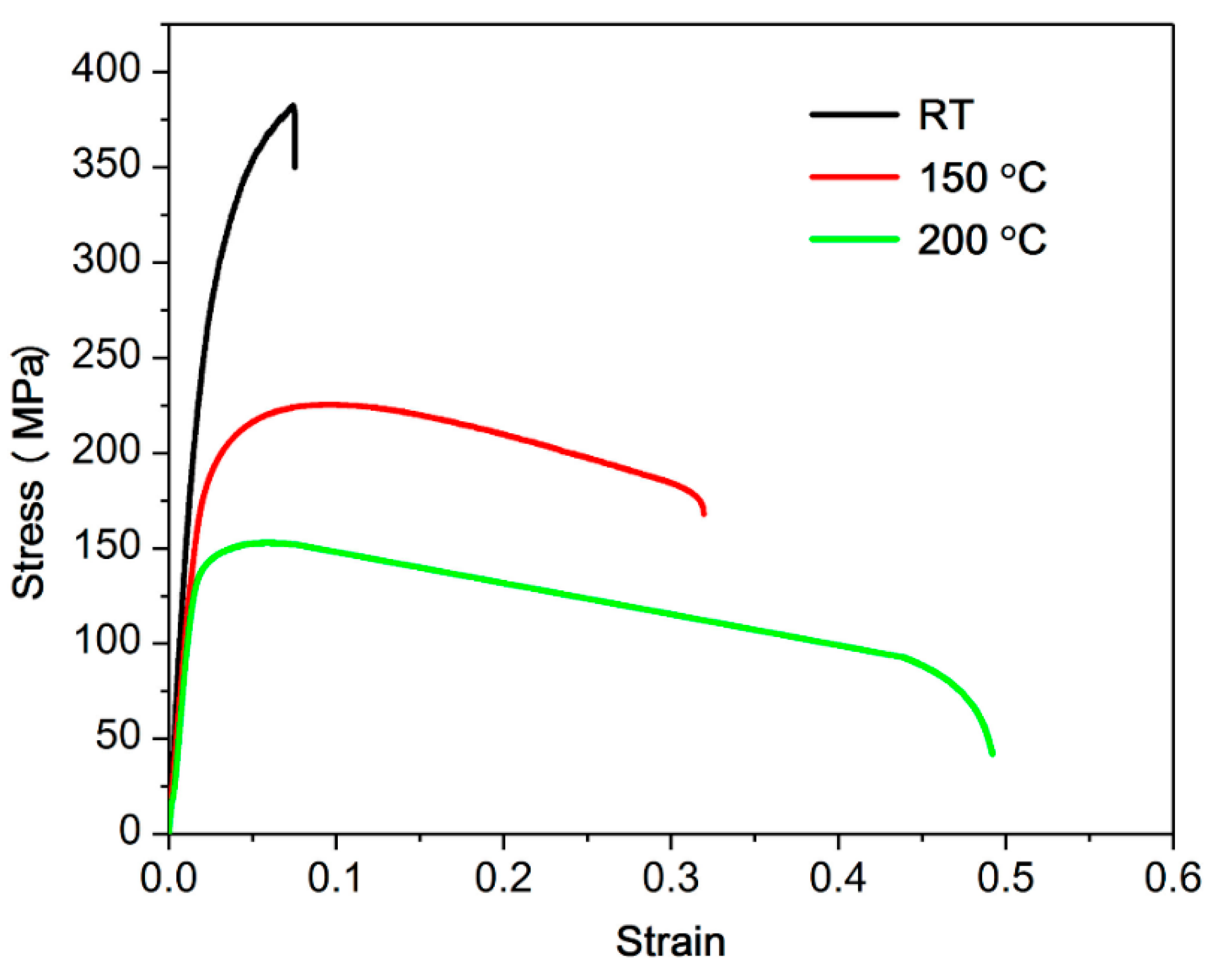
  • The yield strength (YS), ultimate tensile strength (UTS) and elongation (EL) of the as-extruded AZXSE91000 alloy were 351 MPa, 383 MPa and 7.4% at room temperature, respectively. Those were 184 MPa, 225 MPa and 31.8% at 150 °C.
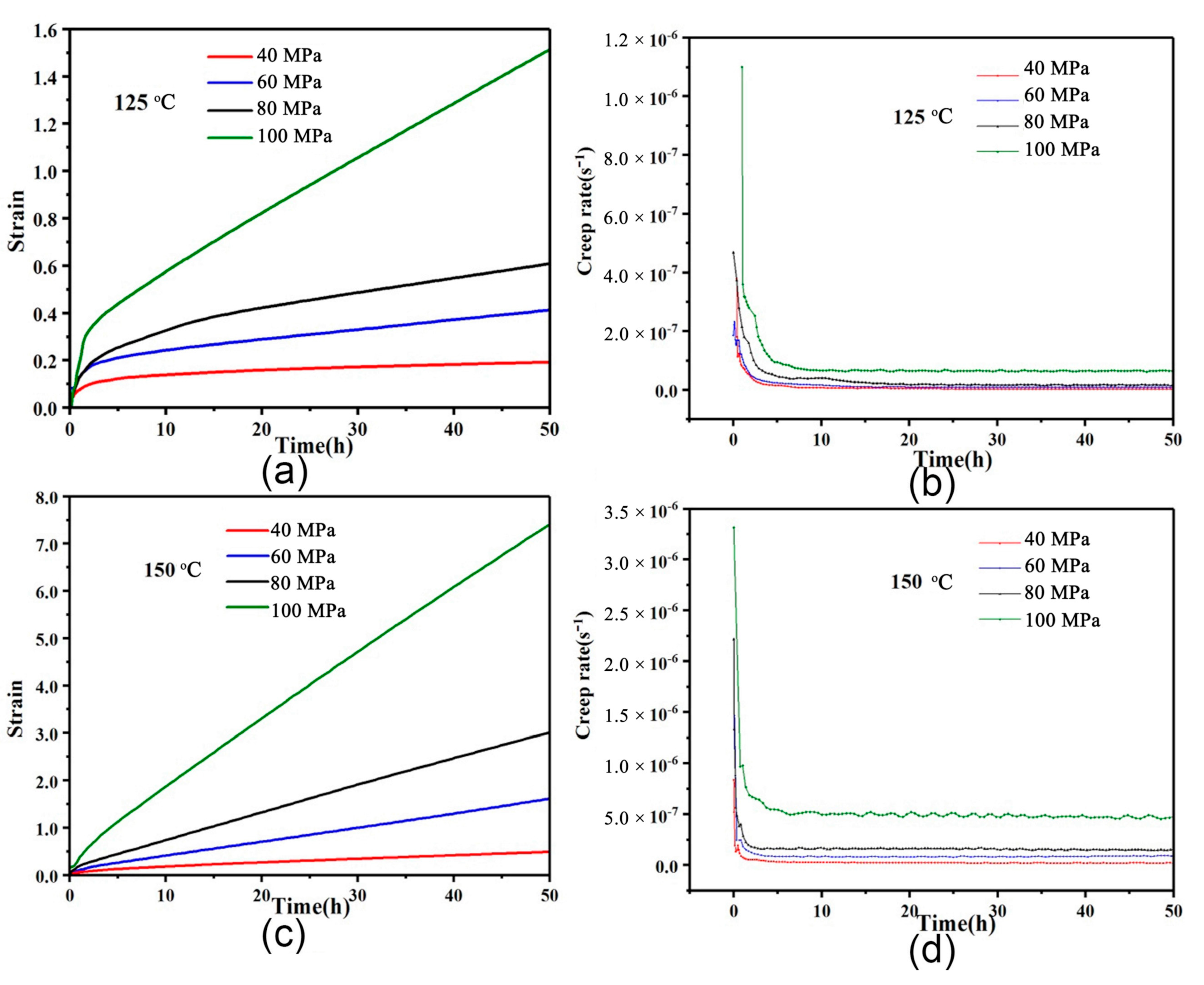
  • The steady creep rates of the as-extruded AZXSE91000 alloy could be comparable with that of the as-cast AZ91 alloy under similar experimental condition, whose values were 2.6 × 10⁸ s−1 and 9.3 × 10⁻⁸ s−1 at 150 °C/40 MPa and 150 °C/60 MPa respectively.
  • The creep stress exponent n of the as-extruded AZXSE91000 alloy was 3.0 and 3.3 at a temperature of 125 °C and 150 °C respectively, under a stress of 40–100 MPa. The creep activation energy ranged from 150 to 190 kJ/mol within the stress range of 40–100 MPa.
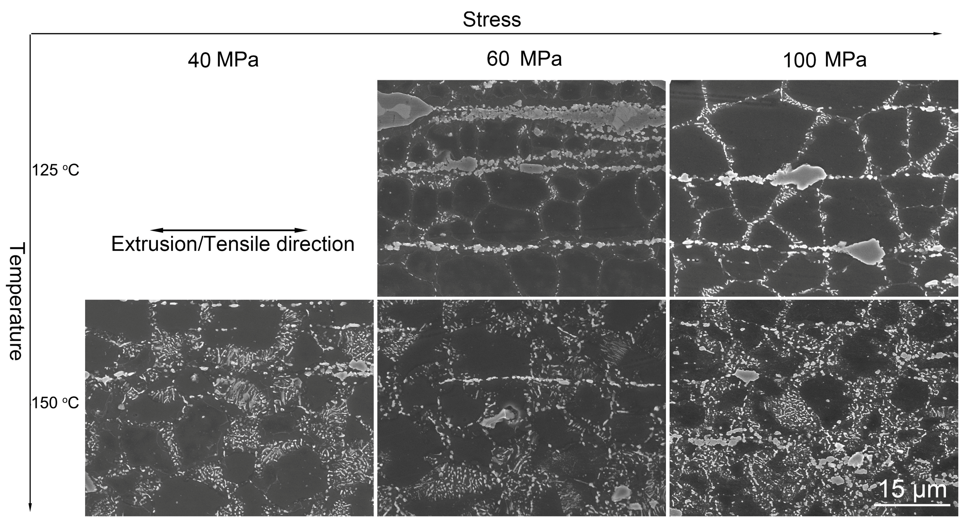
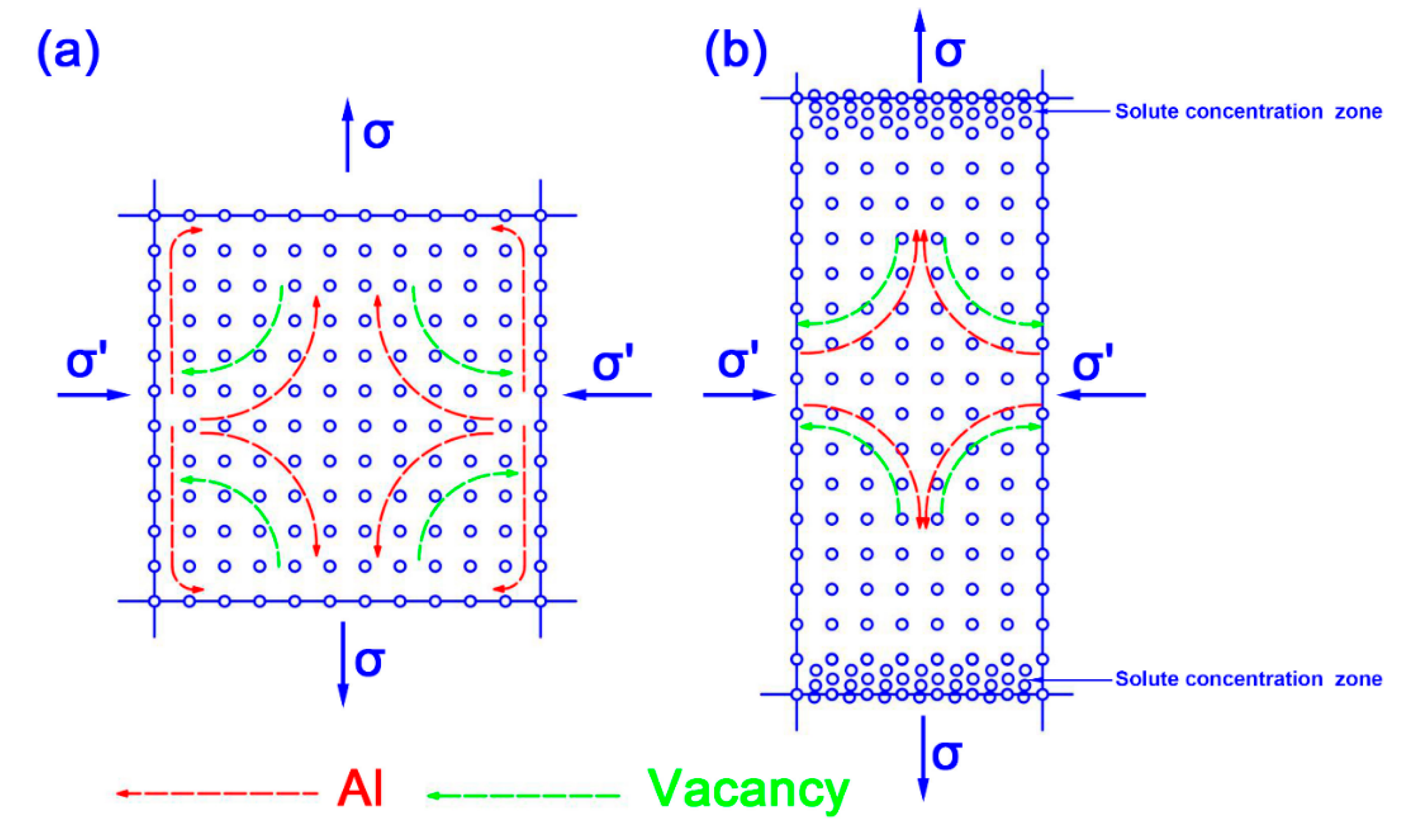
  • Dislocation climbing and grain boundary slip should dominantly contribute to the creep of the as-extruded AZXSE91000 alloy. The asymmetric discontinuous precipitation in crept samples revealed that diffusion played an unneglected role during the creep process.

Author Contributions

Conceptualization, L.C. and C.C.; methodology, F.W.; validation, W.P., H.M., T.L., C.Y. and X.M.; investigation, C.Q., Y.Z. and C.C.; resources, L.C.; data curation, C.Q., Y.Z. and C.C.; writing—original draft preparation, C.C.; writing—review and editing, L.C.; visualization, F.W.; funding acquisition, L.C. and Z.C.

Funding

This work was funded by the National Natural Science Foundation of China (No. U1710113), China Postdoctoral Science Foundation (No. 2017M622903), Personnel Training Project of Shanxi Province Graduate Training Base (No. 2018JD33) and TAI YUAN UNIVERSITY OF SCIENCE AND TECHNOLOGY SCIENTIFIC RESEARCH INITIAL FUNDING (No. 20192003).

Conflicts of Interest

The authors declare no conflict of interest.

References

  1. AlHazaa, A.N.; Shar, M.A.; Atieh, A.M.; Nishikawa, H. Transient liquid phase bonding of magnesium alloy AZ31 using Cu coatings and Cu coatings with Sn interlayers. Metals 2018, 8, 60. [Google Scholar] [CrossRef]
  2. Che, C.; Cai, Z.; Cheng, L.; Meng, F.; Yang, Z. The microstructures and tensile properties of as-extruded Mg–4Sm–xZn–0.5Zr (x = 0, 1, 2, 3, 4 wt%) alloys. Metals 2017, 7, 281. [Google Scholar] [CrossRef]
  3. Dharmendra, C.; Rao, K.P.; Suresh, K.; Hort, N. Hot deformation behavior and processing map of Mg-3Sn-2Ca-0.4Al-0.4Zn alloy. Metals 2018, 8, 216. [Google Scholar] [CrossRef]
  4. Guan, K.; Meng, F.; Qin, P.; Yang, Q.; Zhang, D.; Li, B.; Sun, W.; Lv, S.; Huang, Y.; Hort, N.; et al. Effects of samarium content on microstructure and mechanical properties of Mg–0.5Zn–0.5Zr alloy. J. Mater. Sci. Technol. 2019, 35, 1368–1377. [Google Scholar] [CrossRef]
  5. Majhi, J.; Mondal, A.K. Microstructure and impression creep characteristics of squeeze-cast AZ91 magnesium alloy containing Ca and/or Bi. Mater. Sci. Eng. A 2019, 744, 691–703. [Google Scholar] [CrossRef]
  6. Pan, F.; Yang, M.; Chen, X. A review on casting magnesium alloys: Modification of commercial alloys and development of new alloys. J. Mater. Sci. Technol. 2016, 32, 1211–1221. [Google Scholar] [CrossRef]
  7. Dogan, E.; Vaughan, M.W.; Wang, S.J.; Karaman, I.; Proust, G. Role of starting texture and deformation modes on low-temperature shear formability and shear localization of mg–3Al–1Zn alloy. Acta Mater. 2015, 89, 408–422. [Google Scholar] [CrossRef]
  8. Yoon, D.J.; Kim, E.Z.; Na, K.H.; Lee, Y.S. A study on the forming characteristics of AZ31B mg alloy in a combined forward-backward extrusion at warm temperatures. Appl. Sci. 2018, 8, 2187. [Google Scholar] [CrossRef]
  9. Liu, W.J.; Jiang, B.; Luo, S.Q.; Liu, B. Formation and characterization of hot tearing in AZ series alloys. Int. J. Mater. Res. 2018, 109, 694–698. [Google Scholar] [CrossRef]
  10. Pan, H.C.; Ren, Y.P.; Fu, H.; Zhao, H.; Wang, L.Q.; Meng, X.Y.; Qin, G.W. Recent developments in rare-earth free wrought magnesium alloys having high strength: A review. J. Alloys Compd. 2016, 663, 321–331. [Google Scholar] [CrossRef]
  11. You, S.; Huang, Y.; Kainer, K.U.; Hort, N. Recent research and developments on wrought magnesium alloys. J. Magnes. Alloy 2017, 5, 239–253. [Google Scholar] [CrossRef]
  12. Jia, W.T.; Ma, L.F.; Le, Q.C.; Zhi, C.C.; Liu, P.T. Deformation and fracture behaviors of AZ31B Mg alloy at elevated temperature under uniaxial compression. J. Alloys Compd. 2019, 783, 863–876. [Google Scholar] [CrossRef]
  13. Zhi, C.C.; Ma, L.F.; Huang, Q.X.; Huang, Z.Q.; Lin, J.B. Improvement of magnesium alloy edge cracks by multi-cross rolling. J. Mater. Process. Technol. 2018, 255, 333–339. [Google Scholar] [CrossRef]
  14. Zeng, Z.R.; Zhu, Y.M.; Liu, R.L.; Xu, S.W.; Davies, C.H.J.; Nie, J.F.; Birbilis, N. Achieving exceptionally high strength in mg-3Al-1Zn-0.3Mn extrusions via suppressing intergranular deformation. Acta Mater. 2018, 160, 97–108. [Google Scholar] [CrossRef]
  15. Mazraeshahi, E.M.; Nami, B.; Miresmaeili, S.M.; Tabatabaei, S.M. Effect of Si on the creep properties of AZ61 cast magnesium alloy. Mater. Des. 2015, 76, 64–70. [Google Scholar] [CrossRef]
  16. Srinivasan, A.; Swaminathan, J.; Gunjan, M.K.; Pillai, U.T.S.; Pai, B.C. Effect of intermetallic phases on the creep behavior of AZ91 magnesium alloy. Mater. Sci. Eng. A 2010, 527, 1395–1403. [Google Scholar] [CrossRef]
  17. Nami, B.; Shabestari, S.G.; Razavi, H.; Mirdamadi, S.; Miresmaeili, S.M. Effect of Ca, RE elements and semi-solid processing on the microstructure and creep properties of AZ91 alloy. Mater. Sci. Eng. A 2011, 528, 1261–1267. [Google Scholar] [CrossRef]
  18. Esgandari, B.A.; Mehrjoo, H.; Nami, B.; Miresmaeili, S.M. The effect of Ca and RE elements on the precipitation kinetics of Mg17Al12 phase during artificial aging of magnesium alloy AZ91. Mater. Sci. Eng. A 2011, 528, 5018–5024. [Google Scholar] [CrossRef]
  19. Che, C.; Cai, Z.; Yang, X.; Cheng, L.; Du, Y. The effect of co-addition of Si, Ca and RE on microstructure and tensile properties of as-extruded AZ91 alloy. Mater. Sci. Eng. A 2017, 705, 282–290. [Google Scholar] [CrossRef]
  20. Mo, N.; Tan, Q.; Bermingham, M.; Huang, Y.; Dieringa, H.; Hort, N.; Zhang, M.-X. Current development of creep-resistant magnesium cast alloys: A review. Mater. Des. 2018, 155, 422–442. [Google Scholar] [CrossRef]
  21. Kondori, B.; Mahmudi, R. Effect of ca additions on the microstructure and creep properties of a cast Mg–Al–Mn magnesium alloy. Mater. Sci. Eng. A 2017, 700, 438–447. [Google Scholar] [CrossRef]
  22. Wang, Y.; Choo, H. Influence of texture on hall–petch relationships in an Mg alloy. Acta Mater. 2014, 81, 83–97. [Google Scholar] [CrossRef]
  23. Yu, H.H.; Xin, Y.C.; Wang, M.Y.; Liu, Q. Hall-petch relationship in Mg alloys: A review. J. Mater. Sci. Technol. 2018, 34, 248–256. [Google Scholar] [CrossRef]
  24. Yuan, W.; Panigrahi, S.K.; Su, J.Q.; Mishra, R.S. Influence of grain size and texture on hall-petch relationship for a magnesium alloy. Scr. Mater. 2011, 65, 994–997. [Google Scholar] [CrossRef]
  25. Yuan, G.Y.; Sun, Y.S.; Ding, W.J. Effects of bismuth and antimony additions on the microstructure and mechanical properties of AZ91 magnesium alloy. Mater. Sci. Eng. A 2001, 308, 38–44. [Google Scholar]
  26. Zhu, S.M.; Easton, M.A.; Gibson, M.A.; Dargusch, M.S.; Nie, J.F. Analysis of the creep behaviour of die-cast Mg–3Al–1Si alloy. Mater. Sci. Eng. A 2013, 578, 377–382. [Google Scholar] [CrossRef]
  27. Yin, D.D.; Wang, Q.D.; Boehlert, C.J.; Ding, W.J. Creep and fracture behavior of as-cast Mg–11Y–5Gd–2Zn–0.5Zr (wt%). J. Mater Sci. 2012, 47, 6263–6275. [Google Scholar] [CrossRef]
  28. Zhang, D.D.; Guan, K.; Yang, Q.; Jiang, B.; Sun, C.; Wang, N.; Li, B.S.; Zhang, D.P.; Li, X.L.; Liu, X.J.; et al. Microstructures, mechanical properties and creep behavior of a Mg-3Yb-0.6Zn-0.4Zr casting alloy. Mater. Sci. Eng. A 2019, 745, 360–368. [Google Scholar] [CrossRef]
  29. Somekawa, H.; Hirai, K.; Watanabe, H.; Takigawa, Y.; Higashi, K. Dislocation creep behavior in Mg–Al–Zn alloys. Mater. Sci. Eng. A 2005, 407, 53–61. [Google Scholar] [CrossRef]
  30. Watanabe, H.; Mukai, T.; Kohzu, M.; Tanabe, S.; Higashi, K. Effect of temperature and grain size on the dominant diffusion process for superplastic flow in an AZ61 magnesium alloy. Acta Mater. 1999, 47, 3753–3758. [Google Scholar] [CrossRef]
  31. Chelliah, N.M.; Sudarshan; Kraemer, L.; Singh, H.; Surappa, M.K.; Raj, R. Stress–rupture measurements of cast magnesium strengthened by in-situ production of ceramic particles. J. Magnes. Alloy. 2017, 5, 225–230. [Google Scholar] [CrossRef]
  32. Nami, B.; Razavi, H.; Mirdamadi, S.; Shabestari, S.G.; Miresmaeili, S.M. Effect of Ca and rare earth elements on impression creep properties of AZ91 magnesium alloy. Metall. Mater. Trans. A 2010, 41, 1973–1982. [Google Scholar] [CrossRef]
  33. Wang, H.; Wang, Q.; Yin, D.; Yuan, J.; Ye, B. Tensile creep behavior and microstructure evolution of extruded Mg–10Gd–3Y–0.5Zr (wt%) alloy. Mater. Sci. Eng. A 2013, 578, 150–159. [Google Scholar] [CrossRef]
  34. Wadsworth, J.; Ruano, O.A.; Sherby, O.D. Denuded zones, diffusional creep, and grain boundary sliding. Mater. Sci. Eng. A 2002, 33, 219–229. [Google Scholar] [CrossRef]
  35. Nabarro, F.R.N. Creep in commercially pure metals. Acta Mater. 2006, 54, 263–295. [Google Scholar] [CrossRef]
Figure 1. The mechanical drawing of the tensile creep sample and tensile sample (unit is millimeter).
Metals 09 00954 g001
Figure 2. The XRD patterns of the as-cast AZXSE91000 sample for (a), solution-treated sample for (b) and as-extruded sample for (c).
Metals 09 00954 g002
Figure 3. The OM and SEM images of the as-cast, solution-treated and as-extruded AZXSE91000: (a,b) as-cast sample; (c,d) solution-treated sample; (e,f) as-extruded sample (ED represents extrusion direction; RD represents radial direction).
Metals 09 00954 g003
Figure 4. (a) Electron back scattered diffraction (EBSD) inverse pole figure (IPF) map and pole figures of the as-extruded AZXSE91000 alloy; (b) the recrystallized grains distribution map and the histogram of the recrystallization statistics and (c) the histogram of the misorientation angle distribution.
Metals 09 00954 g004
Figure 5. Engineering stress–strain curves of the as-extruded AZXSE91000 alloy at room temperature, 150 °C and 200 °C, respectively.
Metals 09 00954 g005
Figure 6. (a) A bright field TEM micrograph of the tensile sample of the as-extruded AZXSE91000 alloy at 200 °C; (b) the high resolution transmission electron microscopy (HRTEM) micrograph corresponding to the yellow rectangle zone in Figure 6a; (c) the enlarged dark field TEM micrograph corresponding to the red rectangle zone in Figure 6a and (d) the HRTEM micrograph corresponding to the blue rectangle zone in Figure 6c.
Metals 09 00954 g006
Figure 7. Creep curves and corresponding creep rate-time curves of the as-extruded AZXSE91000 alloy at 125–150 °C, 40–100 MPa.
Metals 09 00954 g007
Figure 8. Variation of the steady creep rate against applied stress and temperature.
Metals 09 00954 g008
Figure 9. The typical SEM microstructures of the crept samples at temperature of 125–150 °C, under a stress of 40–100 MPa after 50 h.
Metals 09 00954 g009
Figure 10. The atom and vacancy diffusion flow schematic diagram in the crept as-extruded AZXSE91000 alloy.
Metals 09 00954 g010
Figure 11. A detailed SEM micrograph of the crept sample under the condition of 125 °C/100 MPa.
Metals 09 00954 g011
Table 1. Chemical component analysis of the as-cast AZXSE91000 alloy.
Nominal AlloyComposition (wt.%)
AlZnCaSiLaCeMg
Mg-9Al-Zn-0.5RE-0.5Ca-0.5Si9.161.120.450.490.190.32Bal.
Table 2. Tensile properties of the as-extruded AZXSE91000 and AZXSE91100 alloy.
AlloysTemperatureUTS (MPa)YS (MPa)EL
AZXSE91000R.T.3833517.4%
150 °C22518431.8%
200 °C15313649%
AZXSE91100 [19]R.T.3182789.2%
150 °C23022225.9%
200 °C14813927.5%
Table 3. The creep experimental results of the as-extruded AZXSE91000 alloy at 125–150 °C/40–100 MPa and steady creep rate of the as-cast AZ91 alloy.
AlloyConditionCreep Strain ε (%; 50 h)Creep Life (h)Steady-State Creep Rate (s−1)
As-extruded AZXSE91000 alloy125 °C/40 MPa0.19503.6 × 10−09
125 °C/60 MPa0.31509.7 × 10−09
125 °C/80 MPa0.61502.1 × 10−08
125 °C/100 MPa1.52506.4 × 10−08
150 °C/40 MPa0.49502.6 × 10−08
150 °C/60 MPa1.61509.3 × 10−08
150 °C/80 MPa3.00501.3 × 10−07
150 °C/100 MPa4.58506.0 × 10−07
As-cast AZ91 [25]150 °C/50 MPa--5.0 × 10−08

