
Chloride Transport Characteristics of Concrete Exposed to Coastal Dredger Fill Silty Soil Environment

1
College of Civil Engineering and Architecture, Wenzhou University, Wenzhou 325035, China
2
Country Key Laboratory of Engineering and Technology for Soft Soil Foundation and Tideland Reclamation of Zhejiang Province, Wenzhou 325035, China
3
Wenzhou Engineering Technical Research Center on Building Energy Conservation and Emission Reduction & Diaster Prevention and Mitigation, Wenzhou 325035, China
4
Zhejiang Collaborative Innovation Center of Tideland Reclamation and Ecological Protection, Wenzhou 325035, China
*
Author to whom correspondence should be addressed.
Buildings 2023, 13(9), 2398; https://doi.org/10.3390/buildings13092398
Submission received: 26 August 2023
/
Revised: 10 September 2023
/
Accepted: 20 September 2023
/
Published: 21 September 2023
(This article belongs to the Special Issue Corrosion and Durability of Building Materials)
Abstract
:In contrast to the marine environment, coastal regions encompass substantial saline soils characterized by complex corrosive chemical compositions. This poses notable challenges to the durability of concrete structures erected in coastal dredger fill silty soil environments. This research undertook concrete chloride corrosion assessments in both a dredger fill silty soil environment and a simulated solution environment. The findings demonstrated a progressive escalation in the free chloride concentration within concrete specimens, as the exposure duration was extended from 60 to 120 d, and discernible convection zones were observed with depths ranging from 6 to 8 mm. The investigation revealed a diminishing trend in the apparent chloride diffusion coefficient, corresponding to the elongation of exposure time and the augmentation of burial depth. Paradoxically, the burial depth and exposure duration exhibited converse effects on the apparent surface chloride concentration. Empirical formulations were derived to express the apparent surface chloride concentrations and apparent chloride diffusion coefficients as dependent on the exposure time and burial depth variables. These models exhibited an excellent goodness of fit, reaching up to 0.96. Notably, concrete specimens interred at a depth of 0.0 m displayed a favorable likeness to the simulated solution environment throughout the 60 d exposure period.
1. Introduction
Reinforced concrete is widely used in industrial and civil buildings due to its adequate strength as well as its practical and economical properties. However, in the complex environments in which it is used, the concrete can be damaged by corrosive media, resulting in the rusting of the steel bars and cracking of the concrete cover, ultimately leading to performance degradation or durability failure of the concrete structure [1,2,3,4].
In recent years, research on the effects of salt corrosion on concrete has been carried out globally. However, the chloride corrosion of concrete in marine environments has long been a research hotspot in academic circles [4,5,6,7,8,9,10]. Pack et al. [5] investigated the durability of 11 concrete bridges that had been used in marine environments for 0.65 to 48.65 years. Based on the test results of the chloride profiles of concrete core samples, the study found that the concrete chloride diffusion coefficients and surface chloride concentrations had obvious time-varying characteristics. According to concrete field exposure tests in marine environments, Jin et al. [6] discussed the chloride ion migration and binding ability of different concrete samples in marine environments. The study found that both fly ash and blast-furnace slag had notable effects on the chloride ion transport and binding capacity of all concrete samples. Based on the results, the researchers proposed an optimal replacement ratio of mineral admixture in marine environments. By determining the chloride content and microstructure of specimens exposed to marine environments for 10 years, Fjendbo et al. [7] found that an obvious area of concrete microstructure changed at 10 mm from the concrete surface, corresponding to a significant peak value of chloride concentration. Furthermore, they analyzed the effects of exposure conditions and mineral admixtures on the corrosion of concrete chloride ions. Aside from field exposure tests, Zhang et al. [8] carried out a large number of laboratory accelerated corrosion tests and conducted in-depth research on the similarity of concrete chloride corrosion in the field exposure test and indoor accelerated corrosion test. In addition, to address the problem of chloride corrosion of concrete in marine environments, Qu et al. [1], Hu et al. [2], and Li et al. [3] have conducted in-depth reviews and analyses in recent years.
Compared to marine environments, coastal and inland salt lake regions contain more extensive saline soils, which tend to have complex corrosive chemical compositions [11]. Therefore, concrete structures built in saline environments also face serious durability problems. Through field exposure tests, Valipour et al. [12] found that chloride corrosion is less damaging to concrete in coastal saline soil environments than in marine splash zones or tidal zones. Sadati et al. [13,14] conducted chloride corrosion tests on concrete used in coastal saline soil environments in the Persian Gulf region and studied the influence of various surface coatings on the chloride penetration resistance of concrete. Al-Tameemi et al. [15] discussed the effects of soil chloride ions on rebar corrosion under varying conditions of concrete cover depth, concrete strength grade, and the exposed surface of concrete specimens. Yang et al. [16] used electrochemical impedance spectroscopy to measure corrosion initiation times and critical chloride concentrations of rebar immersed in simulated saline–alkali solutions based on saline–alkali experimental environments in western China; they also analyzed the influence of sulfate and other ions on corrosion initiation times and critical chloride concentrations. Taking the saline–alkali soil in western China as the experimental background, Zhang et al. [17] simulated the corrosion solution of saline–alkali soil with NaCl and MgSO4 and discussed the effects of different NaCl and MgSO4 ratios on the compressive strength, microstructure, porosity, and chloride corrosion depth of concrete. In addition, Yang et al. [18] and Deng et al. [19,20] conducted comparative studies on the mechanical performance of reinforced concrete components used in saline soil environments.
In sum, previous studies on the chloride corrosion of concrete mainly focused on marine environments; comparatively little research has been carried out on saline soil environments. Moreover, the few existing studies on saline soil environments mainly focused on inland natural saline soils and have usually replaced real saline soil with simulated saline soil solutions [15,16,17,18,19,20]. Therefore, the similarity between the corrosion of concrete specimens in saline soil and that in a simulated solution environment is worthy of investigation. In addition, large portions of the reclamation areas of coastal regions contain a typical “artificial soft soil” of dredger fill silty soil. The corrosive chemical components of the dredger fill silty soil differ significantly from those of natural saline soil [11]. Therefore, research results on the durability of concrete in natural saline soil environments may not be applicable to the concrete structures built in reclamation areas.
Accordingly, this study aims to carry out chloride corrosion tests for concrete in coastal dredger fill silty soil environments. In light of the results of the chloride content detected in the concrete specimens, this paper discusses the chloride transport characteristics of coastal dredger fill silty soil and its simulated solution environment.
2. Materials and Methods
2.1. Materials and Concrete Mix Ratio
The experiment used P·O 42.5 ordinary Portland cement produced by Hailuo Cement Co., Ltd. from Wenzhou city, China. The fine aggregate was standard sand with a particle size range of 0.08–2 mm, and the coarse aggregate was crushed stone with a size of 5–10 mm. Both mixing water and curing water were tap water from the local area of Wenzhou city. The concrete mixing ratio is given in Table 1.
2.2. Preparation of Concrete Specimens
For each working condition, three 100 mm × 100 mm × 100 mm concrete specimens were prepared according to the mixing ratio given in Table 1 for a total of 36 concrete specimens. These concrete specimens were demolded 24 h after casting and cured for 28 days in a standard indoor curing laboratory, with temperatures of 20 ± 2 °C and relative humidity above 95%. According to the tests, the average compressive strength of the standard cubic concrete specimens after 28 days was 42.2 MPa. After curing, five surfaces of each concrete specimen were coated with epoxy resin, leaving only one side as an invasion surface to transport chloride ions during the tests.
2.3. Test Environment and Methods
The buried test of coastal dredger fill silty soil and simulated solution immersion test were conducted to investigate the transport characteristics of chloride ions. The experiment was conducted under natural indoor conditions in Wenzhou city. The averaged environmental temperature and humidity were 18 °C and 80%, respectively. The soil used in the in-ground test was vacuum-preloaded dredger fill silty soil taken from the coastal reclamation area of Wenzhou city, with water content of 48.6%. The components of the corrosive salts in the soil are presented in Table 2.
A portion of the concrete specimens were buried in the soil after the standard 28 d curing period, as shown in Figure 1. The specimens were buried at depths of 0.0 m, 0.5 m, and 1.0 m and were exposed for 60 d, 90 d, and 120 d, respectively. A total of 27 concrete specimens were buried. As the soils for burial were dredger fill silty soils, when the specimen was about to be buried at 0.0 m depth, it was firstly buried halfway into the soil, with gravel placed beneath it, in order to prevent gradual sinking.
The simulated solution was mixed in accordance with Table 2, and the specific chemical components can be found in Table 3.
The concrete samples were immersed in the simulated solution, as shown in Figure 2. During the experiment, water was added to each container every two weeks to prevent concentration changes in the simulated solutions due to water evaporation. The exposure times were set to 60 d, 90 d, and 120 d, respectively.
In each case, once the specified corrosion time had elapsed, the concrete specimens were removed from their respective burial depths and simulated solutions. Upon removal, the concrete specimens were rinsed once with tap water to remove any residual silt and then stored in a dry place for one week. Each specimen was then mounted on a grinder to be ground inwards from the corrosion surface. They were ground every 2 mm to collect the concrete powder obtained. As the exposure times set for the specimens were 60 d, 90 d, and 120 d, the chloride corrosion depth could be shallow, and the chloride concentration in each section of the specimens could be small. Therefore, 10 powder samples were taken for each concrete specimen, i.e., ground to a point 20 mm from the surface of the specimen. Each resulting ground concrete powder sample was filtered through a 0.63 mm sieve and placed in a dryer at a temperature of 105 °C ± 5 °C for two hours. It should be noted that for the concrete specimens at a burial depth of 0.0 m, the sampling location was at the interface between the soil surface and atmosphere. According to the method for determining the free chloride content in concrete powder proposed in the China Concrete Specification (JGJ/T 322–2013), 5 g of concrete powder was taken out, in each case, and put into a beaker; 50 g of pure water was added to prepare the solution. The prepared solution was thoroughly stirred and left for 24 h. Swiss Metrohm 916 Ti-Touch potentiometric titration was used to ascertain the free chloride content of the concrete powder. The procedures for sampling and measuring the chloride content of the concrete specimens are shown in Figure 3.
In addition, for each sample, part of the concrete powder was dried in a vacuum dryer at 40° for 12 h after completion of the tests and then sieved through a 0.074 mm sieve. The post-treatment powder was carried out with XRD detection.
3. Results
3.1. Chloride Profiles
The free chloride concentrations of the concrete specimens in the indoor dredger fill silty soil environment are given in Figure 4.
In the dredger fill silty soil environment, in addition to the concrete specimens embedded at a 0.0 m depth, those embedded at 0.5 m and 1.0 m depths showed an unexpectedly significant tendency for the free chloride concentration to first increase and then decrease. The free chloride concentration of all the samples, regardless of depth, peaked in the range of 6–8mm, indicating an obvious convection zone [21,22,23]. In addition, due to the cumulative effect of chloride ions [1,7], the longer the exposure time of the concrete specimens, the higher the chloride concentrations. The free chloride concentrations of the concrete samples under the same working conditions exhibited the same fluctuating tendency with changes in the corrosion depth, showing little difference. It should be noted that, as the concrete specimens taken from the soil were washed with clean water to remove the silt on the surface, the concentration of water-soluble free chloride ions in the concrete powder at a depth of 2 mm was generally low. Moreover, this operation may also have some influence on the depth of the convective zone.
Further analysis of the data presented in Figure 4 reveals that for concrete specimens buried at a depth of 0.0 m, the convection zone depth was approximately 6 mm. Furthermore, for a burial depth of 0.5 m, the convection zone depth increased by 2 mm during the period from 60 d to 90 d and remained unchanged at 8 mm during the period from 90 d to 120 d. At a burial depth of 1.0 m, the convection zone depth remained at 8 mm for all time periods. The convection zone depths of the concrete specimens buried at 0.5 m and 1.0 m were both greater than those of the concrete specimens buried at 0.0 m. This is because water in the upper part of the soil evaporates more rapidly than that in the lower part, and the water in the soil gradually accumulates in the lower part over time. Thus, the convection effect in the lower part is more powerful than that in the upper part. Therefore, one can reasonably infer that the convection zone depth of the concrete specimen increases as the burial depth increases under the test conditions of this study.
Convection zones were found in concrete specimens at different burial depths because chloride ion penetration into concrete occurs in two stages. When dry concrete specimens come into contact with the soil, the salt solution in the soil enters the concrete via capillary absorption. Under the action of capillary absorption, the transfer rate of the salt solution into the concrete is the fastest, and the internal pores of the concrete can become saturated in a very short time [21]. However, given that the vacuum pre-treated dredger fill silty soil selected for the test with a low water content of approximately 48.6%, the internal pores of the concrete always remain in an unsaturated state. The water evaporation in the soil drives the water evaporation on the surface of the concrete. This leads to a decrease in pore water saturation on the surface layer of the concrete and a gradual increase in the capillary negative pressure on the surface layer of the concrete, which, in turn, causes the pore water to be transported outwards and evaporate [22]. Therefore, the chloride concentration on the concrete surface rises, forming a concentration difference with that inside the concrete, thereby driving the diffusion of chloride ions inwards, eventually resulting in an obvious convection zone on the surface layer of the concrete [23]. Upon passing through the convection zone, the chloride content decreases with increasing depth and shows a gradually slower decreasing tendency until approaching the horizontal level. The gradual decrease in chloride ions is mainly achieved via diffusion [21,22,23,24].
Figure 5 presents the mean free chloride concentration of the concrete specimens in the dredger fill silty soil environment and those in the simulated solution environment at different exposure times.
In the simulated solution environment, as expected, the chloride concentration of the concrete specimens decreased with increasing corrosion depth, and no convection zone appeared. The longer the exposure time, the greater the chloride permeability and penetration depth. The chloride concentrations on all sections of the specimens in the simulated solution under different exposure times were higher than those of the specimens buried at a depth of 0.0 m. The chloride concentration curve for the concrete in the simulated solution environment was similar to that for the concrete specimens buried at 0.5 m and 1.0 m depths in the dredger fill silty soil environment. Concrete in an unsaturated state has a greater difference in capillary pressure in the internal pores, so water transport in the pores results in a convective effect. The transport rate of chloride ions in the unsaturated state is faster than that of chloride ions in the saturated state [23,24]. Although the concrete specimens buried in the soil were in unsaturated states, the chloride ions in the concrete migrated mainly via diffusion using the pore fluid in the concrete. The low water content of the soil caused the water in the concrete specimens to migrate outwards under the negative capillary pressure, thus inhibiting the transport of chloride ions toward the interior of the concrete. Additionally, it makes sense that the chloride content of the concrete specimens would also be at a low level, given that sufficient contact between the concrete specimens and the soil could not be realized. The concrete specimens buried at a 0.0 m depth were only half buried in the soil according to the experimental setup. Therefore, compared to the concrete specimens buried at 0.5 m and 1.0 m depths and immersed in the simulated solution, the transmission channel for chloride ions in the external environment was reduced by about 50%. In addition, water evaporation on the surface soil was more significant during the test, causing the water near the surface of the concrete specimen to migrate outwards under the negative capillary pressure. This did not facilitate the transport of chloride ions into the concrete. Therefore, the concrete specimens buried at a 0.0 m depth were tested for the lowest chloride concentration.
3.2. Time-Varying Chloride Transport
In accordance with the chloride profiles in the stable diffusion zone of the concrete samples under different exposure conditions, the apparent chloride diffusion coefficient of concrete at different exposure times and burial depths was derived by curve fitting via Fick’s second law [1,4], as presented in Figure 6.
Figure 6 shows that when the exposure time was extended from 60 d to 120 d, the apparent chloride diffusion coefficient of concrete under different exposure conditions exhibited a tendency to gradually decrease, and the decreasing speed during the time period from 60 d to 90 d was higher than that during the time period from 90 d to 120 d. This is because the surface pore fluid in the concrete specimens placed in the soil and in the simulated solution was not saturated initially. Under this condition, capillary tension acts to draw the solution into the interior of the concrete until the pores on the surface of the concrete reach a saturated state [23,24]. At this stage, the chloride ions in the solution rapidly diffuse into the concrete. When the pores on the surface of the concrete reach a saturation state, a concentration difference appears between the surface pores and internal pores, causing the chloride ions to continue to diffuse into the interior of the concrete until the concentrations on the surface and in the interior of the concrete become the same. At this point, the rate of diffusion of chloride ions gradually decreases.
In addition, C2S(CaO·Al2O3) hydration produces C-S-H gel during the curing stage of the concrete specimens. When concrete is placed in a corrosive environment, chloride ions penetrating the concrete will react with C3A(3CaO·Al2O3) and C4AF(4CaO·Al2O3·Fe2O3) to form Friedel’s salt [6,25]. Previous studies have reported that the penetration rate of chloride ions can be slowed by binding in concrete [25,26,27]. The combined action of Friedel’s salt and C-S-H gel is essential to the ability to bind chloride ions in concrete [25,26]. The formation of Friedel’s salt and C-S-H gel fills the pore structure inside the concrete, which can block the diffusion channels of solution and chloride ions, eventually resulting in a decrease in the chloride diffusion coefficient during the period from 60 d to 120 d. With the extension of the exposure time, Friedel’s salt and C-S-H gel fill the smaller internal pores and gradually produce tiny cracks, which prove convenient for the diffusion of chloride ions [26]. However, the effect of Friedel’s salt in optimizing the internal pore structure of the concrete is greater than its negative effect of producing additional small cracks [6,27]. In addition, the study by Bullard et al. [28] has shown that concrete typically completes most of its cement hydration within 90 days after casting. In addition, cement hydration was supposed to be the primary factor that led to a rapid decrease in the chloride diffusion coefficient during the early stages [1,5,9]. Therefore, under the combined influence of cement hydration and chloride ion binding, the reduction rate of the chloride diffusion coefficient of the concrete specimens during the 60 d–90 d period was higher than that during the 90 d–120 d period.
Furthermore, the observations gleaned from Figure 6 underscore a noteworthy trend within the milieu of the dredger fill silty soil environment. This trend manifests in the form of escalating compressive stress exhibited in the concrete specimens with a concurrent increase in burial depth. This rise in compressive stress is concomitantly accompanied by a discernible reduction in the apparent chloride diffusion coefficient. Quantitative evaluations affirm that concrete specimens interred at depths of 0.5 m and 1.0 m bear respective loads of approximately 9 kPa and 18 kPa. Although extant literature has consistently evidenced a negative correlation between the apparent chloride diffusion coefficient of concrete and escalating compressive stress [29,30,31,32], it is pivotal to recognize that the compressive stress engendered via the subsoil conditions in this present study remains markedly subordinate in magnitude to the measured concrete compressive strength. Consequently, the influence of loading on the apparent chloride diffusion coefficient within the purview of this research assumes a stance of marginal insignificance. The reduction in the apparent chloride diffusion coefficient of concrete with progressive increments in the interment depth of the concrete specimens could plausibly be ascribed to the nuanced heterogeneity in soil moisture content across varying depths of interment. This, in turn, gives rise to corresponding differentials in the extent of concrete hydration.
As shown in Figure 7, the apparent surface chloride concentration in the dredger fill silty soil environment increased as exposure time increased. Due to the short exposure time, the apparent surface chloride concentration showed a relatively fast growth rate. This is consistent with research findings on concrete in marine environments [33,34,35,36]. Previous studies have shown that the concentration of chloride on the surface of concrete increases rapidly in the initial phase of exposure to chloride [33]. Linear, square-root, and exponential functions are often used to represent the relationship between the increases in surface chloride concentration and exposure time [34,35,36].
Existing studies have shown that compressive stress has almost no effect on the chloride concentration on the concrete surface [37,38]. In this study, as shown in Figure 7, in the dredger fill silty soil environment, the apparent surface chloride concentration of concrete showed an almost linearly increasing tendency with increasing specimen burial depth. The reason for this may not be related to soil compressive stress; rather, as discussed above, the water content in the surface soil is limited, so as burial depth increases, the water content gradually increases, which forms satisfactory drying–wetting conditions. This encourages chloride ions to penetrate the concrete [21,22,23,24].
In addition, as shown in Figure 6 and Figure 7, both the apparent chloride diffusion coefficient and apparent surface chloride concentration varied with changes in exposure time t and burial depth b. Therefore, assuming that these two parameters increase exponentially with exposure time and have a linear functional relationship with burial depth, Equations (1) and (2) give the respective surface-fitting results:
The goodness of fit obtained via the two fitting formulas both reached 0.965, indicating that these formulas may reflect the correlation of the apparent chloride diffusion coefficient and apparent surface chloride concentration of concrete changing with exposure time t and burial depth b. However, because the fitting results were obtained based on the limited experimental data in this current work, further studies should be carried out to obtain a more accurate relational function.
3.3. Similarity Analysis
To explore the similarities between chloride ion transport in concrete specimens in the dredger fill silty soil environment and simulated solution environment, it is assumed that the ratio of the durability parameters of concrete in the two environments is the similarity index λ [8,9]. On this basis, the similarity index λD of the apparent chloride diffusion coefficient and the similarity index λCs of the apparent surface chloride concentration can be calculated via Equations (3) and (4), respectively.
where D′ and are the apparent chloride diffusion coefficient and apparent surface chloride concentration of concretes in dredger fill silty soil, respectively; D and Cs are the corresponding parameters in the simulated solution environment.
The similarity indexes of concrete specimens in the dredger fill silty soil environment and simulated solution environment are calculated, as shown in Figure 8.
Figure 8 clearly illustrates that the burial depth and exposure time of the concrete specimens had a highly significant effect on the similarity indexes in the two test environments. According to the definition of the similarity index λ, the closer this value is to 1, the more similar the chloride corrosion is in the two test environments. As shown in Figure 8, after an exposure period of 60 d in the corrosive environment, a satisfactory similarity of chloride corrosion occurred for the concrete specimens buried at a depth of 0.0 m in the dredger fill silty soil environment and specimens in the simulated solution environment. The similarity indexes λD and λCs were 1.07 and 1.11, respectively. The chloride diffusion coefficient of concrete mainly depended on the ratio of water to cement, as has been shown in previous studies [39]. In this work, the water–cement ratio of all concrete specimens was set to 0.4. Therefore, as shown in Figure 8a, with the extension of the exposure time, the similarity index λD gradually approached 1.0, due to the cement hydration and chloride ion binding effect of the concrete specimens. In addition, λCs gradually rose with the elongation of the exposure time, as seen in Figure 8b. This is because the chloride ion transport mechanisms and external chloride ion sources in the two experimental environments are different, which, as discussed above, affects the chloride concentration accumulation rate.
3.4. Concrete Corrosion Products Analysis
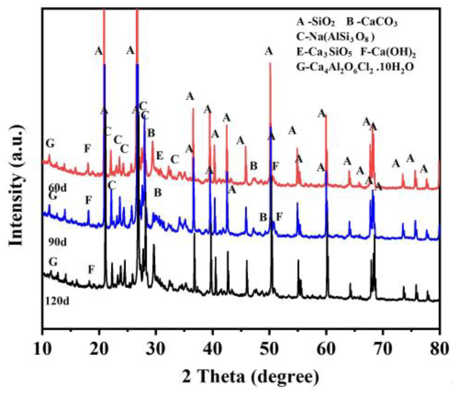
XRD analysis was carried out on the concrete powder at 3 mm and 5 mm from the surface of the concrete specimens in order to detect the concrete corrosion products. The XRD test results for the dredger fill silty soil environment and simulated solution environment are shown in Figure 9 and Figure 10.
For all of the concrete specimens tested in both the dredger fill silty soil environment and simulated solution environment, SiO2, CaCO3, Na(AlSi3O8), AlKO8Si3, Ca3O5Si, Ca(OH)2, and Friedel’s salt (Ca4Al2O6Cl2·10H2O) were detected. SiO2 and CaCO3 mainly result from incomplete cement hydration, silica fume particles in the concrete, and sand particles produced during the grinding process; Ca(OH)2 is the product of cement hydration; Ca3O5Si is one of the main components of cement; and Na(AlSi3O8) and AlKO8Si3 mainly result from the aggregates of the concrete specimens.
Friedel’s salt plays a key role in the binding of chloride ions in concrete [27,40]. Chloride ion binding slows the rate at which free chloride ions reach the rebar, effectively reducing the chloride ion concentration in the section and delaying the corrosion initiation time of the rebar [27]. As shown in Figure 9 and Figure 10, the intensity, sharpness, and peak area ratio of the XRD diffraction peaks of Friedel’s salt in the dredger fill silty soil environment were all lower than those of the concrete tested in the simulated solution environment. This indicates that in the dredger fill silty soil environment, the crystallization of Friedel’s salt within 5 mm of the concrete surface was unsatisfactory. Under the simulated solution environment, chloride ions could enter the concrete and make full contact with aluminate hydration products, which is conducive to the formation of Friedel’s salt [41]. However, in the dredger fill silty soil environment, the location 5 mm from the concrete surface was in the convection zone, and the concrete was in the unsaturated state, so chloride ions rarely achieved full contact with cement hydration products. In addition, as shown in Figure 9 and Figure 10, the intensity and sharpness of the Ca(OH)2 diffraction peaks were lower than those of the concrete samples in the simulated solution environment. Ca(OH)2 is a product of the cement hydration process, which results in a progressive increase in the pH of the concrete and produces concrete in an alkaline environment. This is very important for the stabilization of Friedel’s salt [42]. Friedel’s salt begins to decompose, and the chloride ions in the concrete gradually increase as the pH falls to 11 [43].
4. Conclusions
The primary objective of this study was to investigate the transport behaviors exhibited via chloride ions within concrete specimens situated within a dredger fill silty soil environment as well as a simulated solution environment. A comparative analysis of the resemblances in concrete chloride corrosion across these two environments was also undertaken. The conclusions drawn from the experimental results are as follows:
- (1)
- In the dredger fill silty soil environment, a direct correlation was observed between the increase in exposure time (ranging from 60 days to 120 days) and the corresponding augmentation in the free chloride content of the concrete specimens. Owing to the relatively diminished moisture content within the soil matrix, a distinct convection zone emerged adjacent to the concrete specimen surfaces at varying depths of interment and exposure durations. This convection zone manifested at an approximate depth of 6 to 8 mm. Furthermore, an elevation in burial depth corresponded to parallel increments in both the convection zone’s depth and chloride content.
- (2)
- In the dredger fill silty soil environment, the apparent chloride diffusion coefficient exhibited a diminishing trend as both the depth of interment and exposure time escalated. Divergent effects were noted concerning the impact of exposure time and burial depth on the apparent surface chloride concentration relative to the chloride diffusion coefficient evident within the concrete samples. Mathematical formulations were devised to represent the concrete’s apparent surface chloride concentrations and apparent chloride diffusion coefficients as dependent on the exposure time and burial depth parameters, yielding an exceptional coefficient of determination of up to 0.96.
- (3)
- The chloride corrosion similarity in the two distinct testing environments was significantly influenced by both the burial depth and exposure time of the concrete specimens. Notably, concrete samples interred at a depth of 0.0 m for a duration of 60 days exhibited satisfactory parallels with those placed within the simulated solution environment, as characterized by similarity indices (λD and λCs) of 1.07 and 1.11, respectively.
- (4)
- In contrast to the simulated solution environment, the space 5 mm from the surface of the concrete in the dredger fill silty soil environment usually remained in an unsaturated state, leading to unsatisfactory crystallization of Friedel’s salt. Therefore, the chloride corrosion potential of concrete may be more severe in the dredger fill silty soil environment.
Author Contributions
Conceptualization, L.W.; methodology, L.W.; software, Y.X.; validation, W.W., Y.X. and X.G.; formal analysis, C.J.; investigation, W.W.; resources, W.W. and C.J.; data curation, W.W.; writing—original draft preparation, C.J.; writing—review and editing, L.W.; visualization, W.W.; supervision, C.J.; project administration, L.W.; funding acquisition, L.W. All authors have read and agreed to the published version of the manuscript.
Funding
This research was funded by the National Natural Science Foundation of China, grant number 52008317, and the Natural Science Foundation of Zhejiang Province, grant number LQ20E080024.
Data Availability Statement
The data presented in this study are available on request from the corresponding author.
Conflicts of Interest
The authors declare no conflict of interest.
References
- Qu, F.L.; Li, W.G.; Dong, W.K.; Tam, V.W.Y.; Yu, T. Durability deterioration of concrete under marine environment from material to structure: A critical review. J. Build. Eng. 2021, 35, 102074. [Google Scholar] [CrossRef]
- Hu, J.Y.; Zhang, S.S.; Chen, E.; Li, W. A review on corrosion detection and protection of existing reinforced concrete (RC) structures. Constr. Build. Mater. 2022, 325, 126718. [Google Scholar] [CrossRef]
- Li, K.F.; Zeng, J.J.; Tang, L.P.; Sorensen, H.E.; Borges, P.C.; Geiker, M.R.; Pedersen, M.T.; Zhang, P.; Surana, S.; Maddalena, R.; et al. Long-term field exposure of structural concretes in marine environment: State-of-the-art review by RILEM TC 289-DCM. Mater. Struct. 2022, 55, 205. [Google Scholar] [CrossRef]
- Wu, L.J.; Li, W.; Yu, X.N. Time-dependent chloride penetration in concrete in marine environments. Constr. Build. Mater. 2017, 152, 406–413. [Google Scholar] [CrossRef]
- Pack, S.W.; Jung, M.S.; Song, H.W.; Kim, S.H.; Ann, K.Y. Prediction of time dependent chloride transport in concrete structures exposed to a marine environment. Cem. Concr. Res. 2010, 40, 302–312. [Google Scholar] [CrossRef]
- Jin, Z.Q.; Zhao, X.; Zhao, T.J.; Li, J.Q. Chloride ions transportation behavior and binding capacity of concrete exposed to different marine corrosion zones. Constr. Build. Mater. 2018, 177, 170–183. [Google Scholar]
- Fjendbo, S.; Sorensen, H.E.; De Weerdt, K.; Jakobsen, U.H.; Geiker, M.R. Correlating the development of chloride profiles and microstructural changes in marine concrete up to ten years. Cem. Concr. Compos. 2022, 131, 104590. [Google Scholar] [CrossRef]
- Zhang, Y.R.; Zhuang, H.X.; Shi, J.L.; Huang, J.; Zhang, J.Z. Time-dependent characteristic and similarity of chloride diffusivity in concrete. Mag. Concr. Res. 2018, 70, 129–137. [Google Scholar] [CrossRef]
- Wu, L.J.; Wang, W.Q.; Jiang, C.C. Study on the similarity of chloride penetration in concrete exposed to field and laboratory conditions. Mater. Struct. 2023, 56, 95. [Google Scholar] [CrossRef]
- Sun, L.; Wang, C.; Zhang, C.W.; Yang, Z.Y.; Li, C.; Qiao, P.Z. Experimental investigation on the bond performance of sea sand coral concrete with FRP bar reinforcement for marine environments. Adv. Struct. Eng. 2023, 26, 533–546. [Google Scholar] [CrossRef]
- Wu, L.J.; Xiang, Z.Y.; Jiang, H.; Liu, M.W.; Ju, X.L.; Zhang, W.X. A Review of Durability Issues of Reinforced Concrete Structures Due to Coastal Soda Residue Soil in China. J. Mar. Sci. Eng. 2022, 10, 1740. [Google Scholar] [CrossRef]
- Valipour, M.; Pargar, F.; Shekarchi, M.; Khani, S.; Moradian, M. In situ study of chloride ingress in concretes containing natural zeolite, metakaolin and silica fume exposed to various exposure conditions in a harsh marine environment. Constr. Build. Mater. 2013, 46, 63–70. [Google Scholar] [CrossRef]
- Sadati, S.; Arezoumandi, M.; Shekarchi, M. Long-term performance of concrete surface coatings in soil exposure of marine environments. Constr. Build. Mater. 2015, 94, 656–663. [Google Scholar] [CrossRef]
- Sadati, S.; Moradllo, M.K.; Shekarchi, M. Long-Term Performance of Silica Fume Concrete in Soil Exposure of Marine Environments. J. Mater. Civ. Eng. 2017, 29, 04017126. [Google Scholar] [CrossRef]
- Al-Tameemi, A.A.; Mahmood, M.S.; Albahadli, N.A.; Alkhudery, H.H.; Alturaihee, R.M. Impact of Soil-Borne Chloride on Rebars Corrosion in Reinforced Concrete Members. J. Eng. Sci. Technol. 2022, 17, 654–672. [Google Scholar]
- Yang, D.Q.; Yan, C.W.; Zhang, J.; Liu, S.G.; Li, J. Chloride threshold value and initial corrosion time of steel bars in concrete exposed to saline soil environments. Constr. Build. Mater. 2021, 267, 120979. [Google Scholar] [CrossRef]
- Zhang, F.; Wei, F.; Wu, X.J.; Hu, Z.P.; Li, X.G.; Gao, L.L. Study on Concrete Deterioration and Chloride Ion Diffusion Mechanism by Different Aqueous NaCl-MgSO4 Concentrations. Buildings 2022, 12, 1843. [Google Scholar] [CrossRef]
- Yang, D.Q.; Yan, C.W.; Liu, S.G.; Zhang, J.; Hu, Z.C. Stress-strain constitutive model of concrete corroded by saline soil under uniaxial compression. Constr. Build. Mater. 2019, 213, 665–674. [Google Scholar] [CrossRef]
- Yan, C.W.; Zhao, J.J.; Liu, S.G.; Zhang, J. Seismic Yield Strength of Reinforced Concrete Bridge Piers in a Saline Soil Environment. J. Perform. Constr. Facil. 2020, 34, 04019114. [Google Scholar] [CrossRef]
- Deng, Y.H.; Yan, C.W.; Li, J.; Liu, S.G.; Zhang, J.; Wang, J.J. Seismic deformation of reinforced concrete piers corroded by saline soil. Bull. Earthq. Eng. 2022, 20, 6763–6788. [Google Scholar] [CrossRef]
- Xu, G.; Li, Y.P.; Su, Y.B.; Xu, K. Chloride ion transport mechanism in concrete due to wetting and drying cycles. Struct. Concr. 2015, 16, 289–296. [Google Scholar]
- Yang, L.F.; Cai, R.; Yu, B. Investigation of computational model for surface chloride concentration of concrete in marine atmosphere zone. Ocean Eng. 2017, 138, 105–111. [Google Scholar] [CrossRef]
- Cai, R.; Hu, Y.S.; Yu, M.; Liao, W.Y.; Yang, L.F.; Kumar, A.; Ma, H.Y. Skin effect of chloride ingress in marine concrete: A review on the convection zone. Constr. Build. Mater. 2020, 262, 120566. [Google Scholar] [CrossRef]
- Zhang, Y.; Di Luzio, G.; Alnaggar, M. Coupled multi-physics simulation of chloride diffusion in saturated and unsaturated concrete. Constr. Build. Mater. 2021, 292, 123394. [Google Scholar] [CrossRef]
- He, H.; Shuang, E.; Wen, T.; Yao, J.; Wang, X.; He, C.; Yu, Y. Employing novel N-doped graphene quantum dots to improve chloride binding of cement. Constr. Build. Mater. 2023, 401, 132944. [Google Scholar] [CrossRef]
- Loser, R.; Lothenbach, B.; Leemann, A.; Tuchschmid, M. Chloride resistance of concrete and its binding capacity—Comparison between experimental results and thermodynamic modeling. Cem. Concr. Compos. 2010, 32, 34–42. [Google Scholar] [CrossRef]
- Yuan, Q.; Shi, C.J.; De Schutter, G.; Audenaert, K.; Deng, D.H. Chloride binding of cement-based materials subjected to external chloride environment—A review. Constr. Build. Mater. 2009, 23, 1–13. [Google Scholar] [CrossRef]
- Bullard, J.W.; Jennings, H.M.; Livingston, R.A. Mechanisms of cement hydration. Cem. Concr. Res. 2011, 41, 1208–1223. [Google Scholar] [CrossRef]
- Wang, H.L.; Dai, J.G.; Sun, X.Y.; Zhang, X.L. Time-Dependent and Stress-Dependent Chloride Diffusivity of Concrete Subjected to Sustained Compressive Loading. J. Mater. Civ. Eng. 2016, 28, 04016059. [Google Scholar] [CrossRef]
- Bao, J.W.; Wang, L.C. Combined effect of water and sustained compressive loading on chloride penetration into concrete. Constr. Build. Mater. 2017, 156, 708–718. [Google Scholar] [CrossRef]
- Zhang, L.H.; Jia, J.Q.; Meng, G.; Zhu, W.Q. Chloride diffusion in concrete subjected to compressive loading. Mag. Concr. Res. 2014, 66, 991–997. [Google Scholar] [CrossRef]
- Xu, J.; Li, F.M. Analytical Model for Load Dependence of Chloride Penetration into Concrete. J. Mater. Civ. Eng. 2017, 29, 04016279. [Google Scholar] [CrossRef]
- Yang, L.F.; Wang, L.; Yu, B. Time-varying behavior and its coupling effects with environmental conditions and cementitious material types on surface chloride concentration of marine concrete. Constr. Build. Mater. 2021, 303, 124578. [Google Scholar] [CrossRef]
- Zhou, S.J. Modeling Chloride Diffusion in Concrete with Linear Increase of Surface Chloride. ACI Mater. J. 2014, 111, 483–490. [Google Scholar]
- Zhou, S.J. Analytical Model for Square Root Increase of Surface Chloride Concentration and Decrease of Chloride Diffusivity. J. Mater. Civ. Eng. 2016, 28, 04015181. [Google Scholar] [CrossRef]
- Cai, R.; Yu, M.; Hu, Y.S.; Yang, L.F.; Ma, H.Y. Influence of data acquisition and processing on surface chloride concentration of marine concrete. Constr. Build. Mater. 2021, 273, 121705. [Google Scholar] [CrossRef]
- Wang, Y.Z.; Lin, C.P.; Cui, Y.Q. Experiments of Chloride Ingression in Loaded Concrete Members under the Marine Environment. J. Mater. Civ. Eng. 2014, 26, 04014012. [Google Scholar] [CrossRef]
- Wu, J.; Li, H.M.; Wang, Z.; Liu, J.J. Transport model of chloride ions in concrete under loads and drying-wetting cycles. Constr. Build. Mater. 2016, 112, 733–738. [Google Scholar] [CrossRef]
- Song, H.W.; Lee, C.H.; Ann, K.Y. Factors influencing chloride transport in concrete structures exposed to marine environments. Cem. Concr. Compos. 2008, 30, 113–121. [Google Scholar] [CrossRef]
- Zhu, Q.; Jiang, L.H.; Chen, Y.; Xu, J.X.; Mo, L.L. Effect of chloride salt type on chloride binding behavior of concrete. Constr. Build. Mater. 2012, 37, 512–517. [Google Scholar] [CrossRef]
- Voinitchi, D.; Julien, S.; Lorente, S. The relation between electrokinetics and chloride transport through cement-based materials. Cem. Concr. Compos. 2008, 30, 157–166. [Google Scholar] [CrossRef]
- Long, W.J.; Zhang, X.H.; Feng, G.L.; Xie, J.; Xing, F.; Dong, B.Q.; Zhang, J.R.; Khayat, K.H. Investigation on chloride binding capacity and stability of Friedel’s salt in graphene oxide reinforced cement paste. Cem. Concr. Compos. 2022, 132, 104603. [Google Scholar] [CrossRef]
- Machner, A.; Hemstad, P.; De Weerdt, K. Towards the Understanding of the pH Dependency of the Chloride Binding of Portland Cement Pastes. Nord. Concr. Res. 2018, 58, 143–162. [Google Scholar] [CrossRef]
Figure 1.
Concrete specimens in the dredger fill silty soil.

Figure 2.
Concrete specimens in the simulated solution.
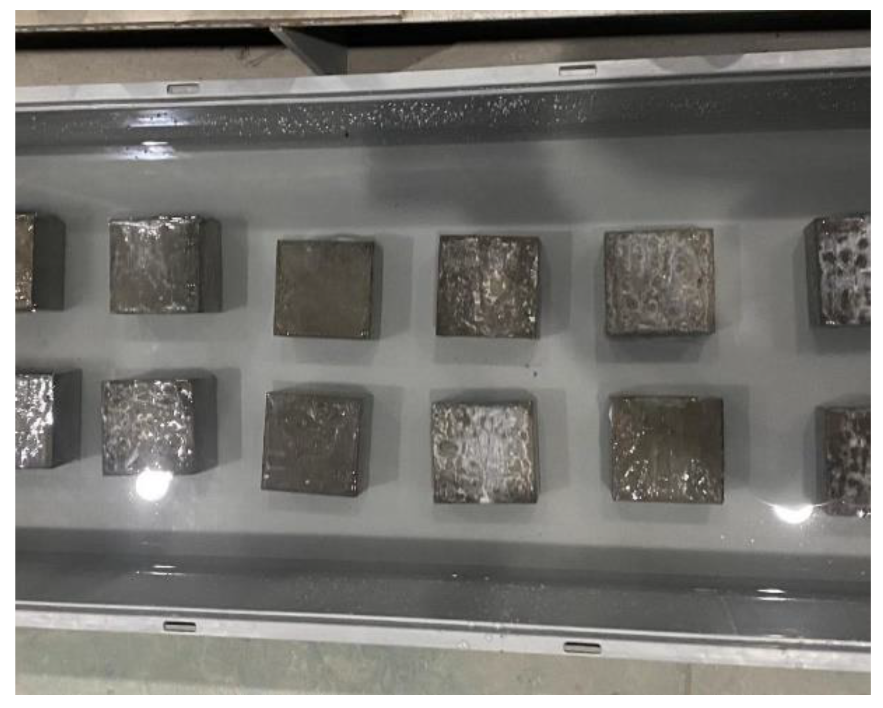
Figure 3.
Concrete specimen sampling and chloride content testing: (a) concrete grinding machine, (b) concrete specimen grinding, (c) concrete powder, and (d) chloride content testing.
Figure 3.
Concrete specimen sampling and chloride content testing: (a) concrete grinding machine, (b) concrete specimen grinding, (c) concrete powder, and (d) chloride content testing.

Figure 4.
Chloride profiles of concrete under dredger fill silty soil environment with different burial depth: (a) burial depth of 0.0 m, (b) burial depth of 0.5 m, and (c) burial depth of 1.0 m.
Figure 4.
Chloride profiles of concrete under dredger fill silty soil environment with different burial depth: (a) burial depth of 0.0 m, (b) burial depth of 0.5 m, and (c) burial depth of 1.0 m.
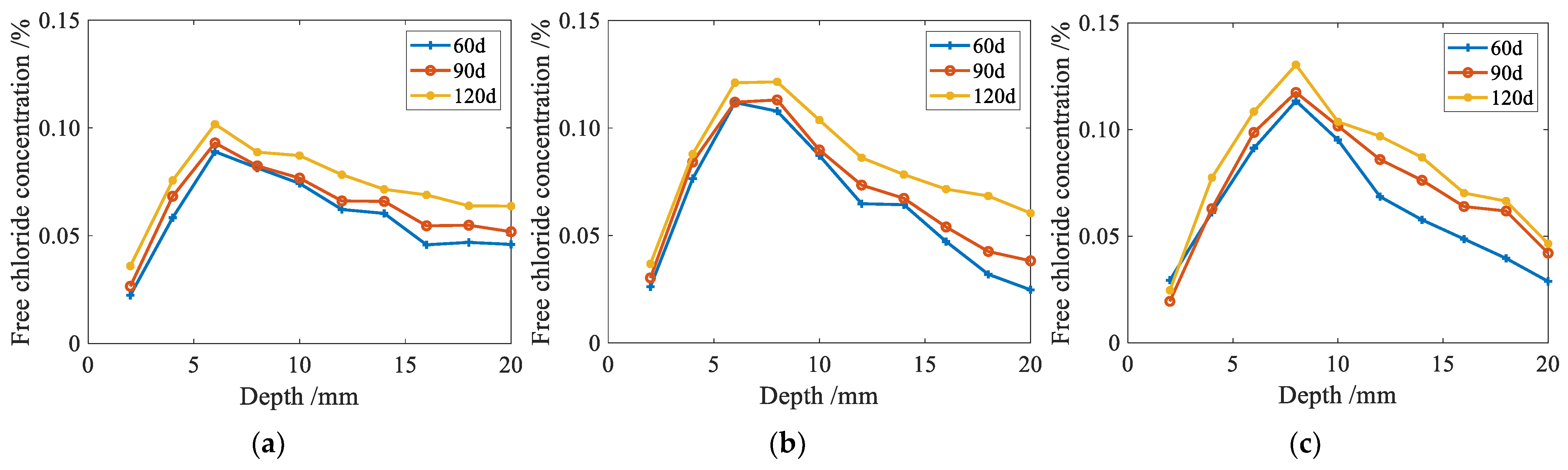
Figure 5.
Chloride profiles of concrete with different exposure times: (a) exposure 60 d, (b) exposure 90 d, and (c) exposure 120 d.
Figure 5.
Chloride profiles of concrete with different exposure times: (a) exposure 60 d, (b) exposure 90 d, and (c) exposure 120 d.

Figure 6.
Apparent chloride diffusion coefficient for different exposure times and burial depths /10−12 m2·s−1.
Figure 6.
Apparent chloride diffusion coefficient for different exposure times and burial depths /10−12 m2·s−1.
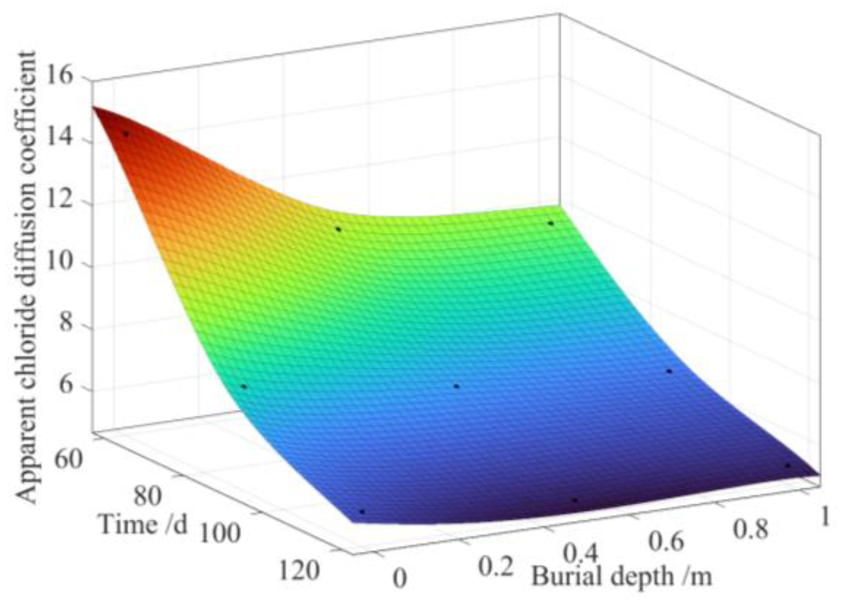
Figure 7.
Apparent surface chloride concentration for different exposure times and burial depths.

Figure 8.
Similarity indexes between two test environments: (a) apparent chloride diffusion coefficient similarity index λD; (b) apparent surface chloride concentration similarity index λCs.
Figure 8.
Similarity indexes between two test environments: (a) apparent chloride diffusion coefficient similarity index λD; (b) apparent surface chloride concentration similarity index λCs.
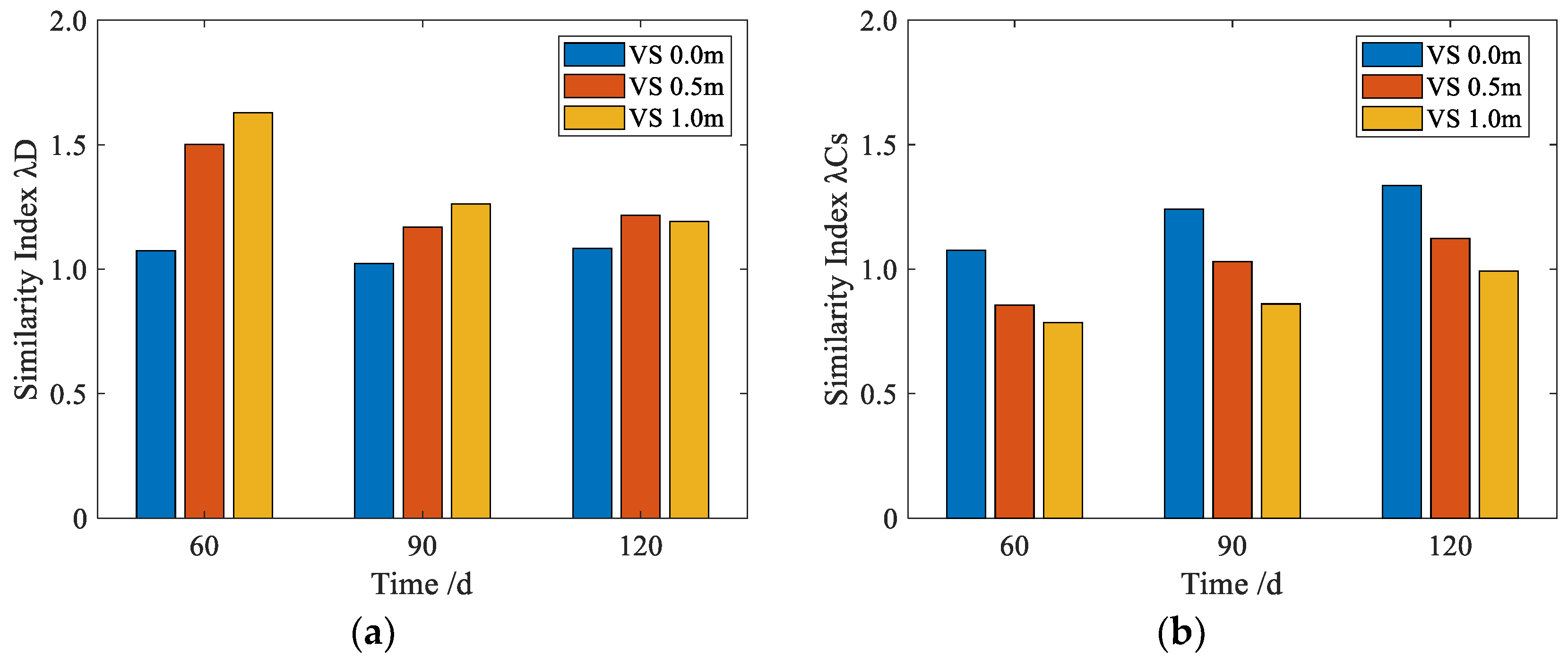
Figure 9.
Concrete corrosion products under the dredger fill silty soil environment.
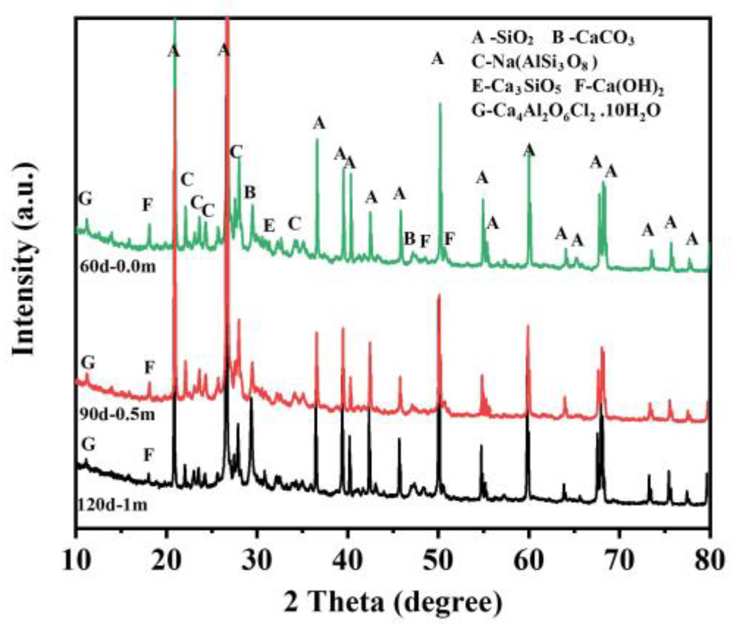
Figure 10.
Concrete corrosion products under the simulated solution environment.

Table 1.
Details of the concrete mixtures.
| Cement/kg | Water/kg | Fine Aggregates/kg | Coarse Aggregates/kg | w/c |
|---|---|---|---|---|
| 475 | 190 | 547 | 1164 | 0.4 |
Table 2.
The components of the corrosive salts in the dredger fill silty soil.
| Components | K | Na | Ca | Mg | Cl− | SO₄2− | HCO3− |
|---|---|---|---|---|---|---|---|
| Molarity (mg/L) | 352 | 4750 | 705 | 315 | 3976 | 573 | 2501 |
| Percentage concentration (%) | 0.0352 | 0.4750 | 0.0705 | 0.0315 | 0.3976 | 0.0573 | 0.2501 |
Table 3.
The chemical components of the simulated solution.
| Components | KCl | NaCl | MgCl2 | CaCl2 | MgSO4 | NaHCO3 |
|---|---|---|---|---|---|---|
| Molarity (mg/L) | 672 | 3175 | 613 | 1958 | 733 | 3573 |
| Percentage concentration (%) | 0.0626 | 0.2961 | 0.0571 | 0.1826 | 0.0683 | 0.3332 |
Disclaimer/Publisher’s Note: The statements, opinions and data contained in all publications are solely those of the individual author(s) and contributor(s) and not of MDPI and/or the editor(s). MDPI and/or the editor(s) disclaim responsibility for any injury to people or property resulting from any ideas, methods, instructions or products referred to in the content. |
© 2023 by the authors. Licensee MDPI, Basel, Switzerland. This article is an open access article distributed under the terms and conditions of the Creative Commons Attribution (CC BY) license (https://creativecommons.org/licenses/by/4.0/).
Share and Cite
MDPI and ACS Style
Wu, L.; Jiang, C.; Wang, W.; Gao, X.; Xia, Y. Chloride Transport Characteristics of Concrete Exposed to Coastal Dredger Fill Silty Soil Environment. Buildings 2023, 13, 2398. https://doi.org/10.3390/buildings13092398
AMA Style
Wu L, Jiang C, Wang W, Gao X, Xia Y. Chloride Transport Characteristics of Concrete Exposed to Coastal Dredger Fill Silty Soil Environment. Buildings. 2023; 13(9):2398. https://doi.org/10.3390/buildings13092398
Chicago/Turabian StyleWu, Lingjie, Chenchi Jiang, Weiqiang Wang, Xiang Gao, and Yufeng Xia. 2023. "Chloride Transport Characteristics of Concrete Exposed to Coastal Dredger Fill Silty Soil Environment" Buildings 13, no. 9: 2398. https://doi.org/10.3390/buildings13092398
Note that from the first issue of 2016, this journal uses article numbers instead of page numbers. See further details here.