
Experimental and Numerical Study of Strengthening Prestressed Reinforced Concrete Beams Using Different Techniques
 , , and
Abstract
:1. Introduction
2. Materials and Methods
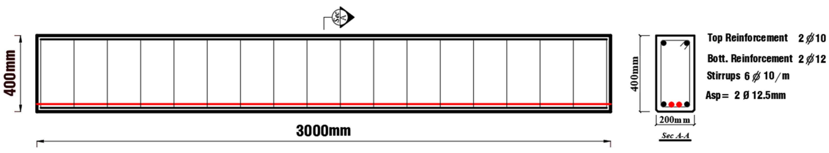
2.1. Experimental Plan
2.2. Material Characteristics
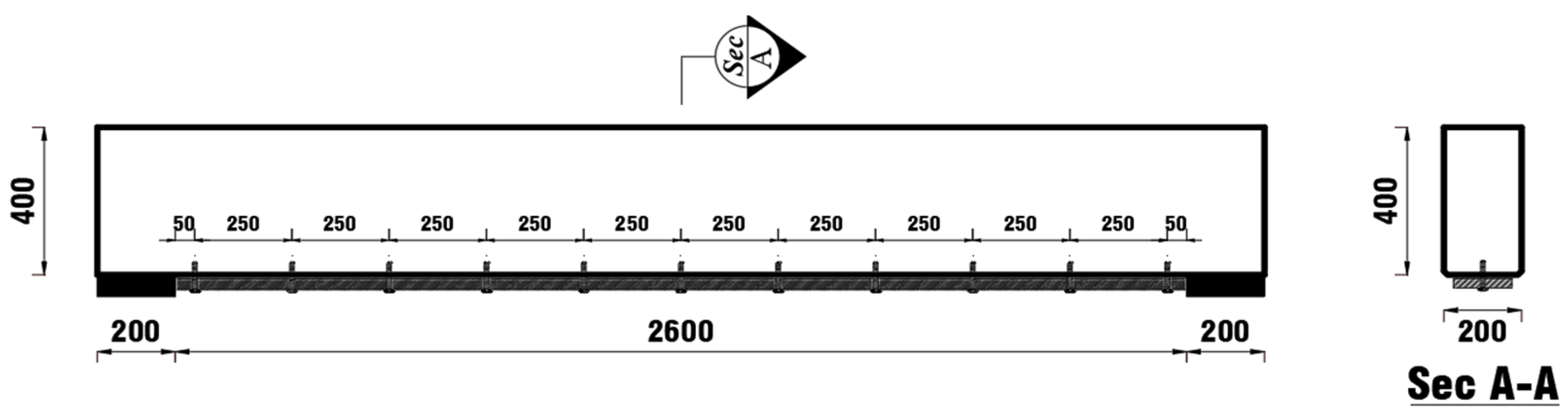
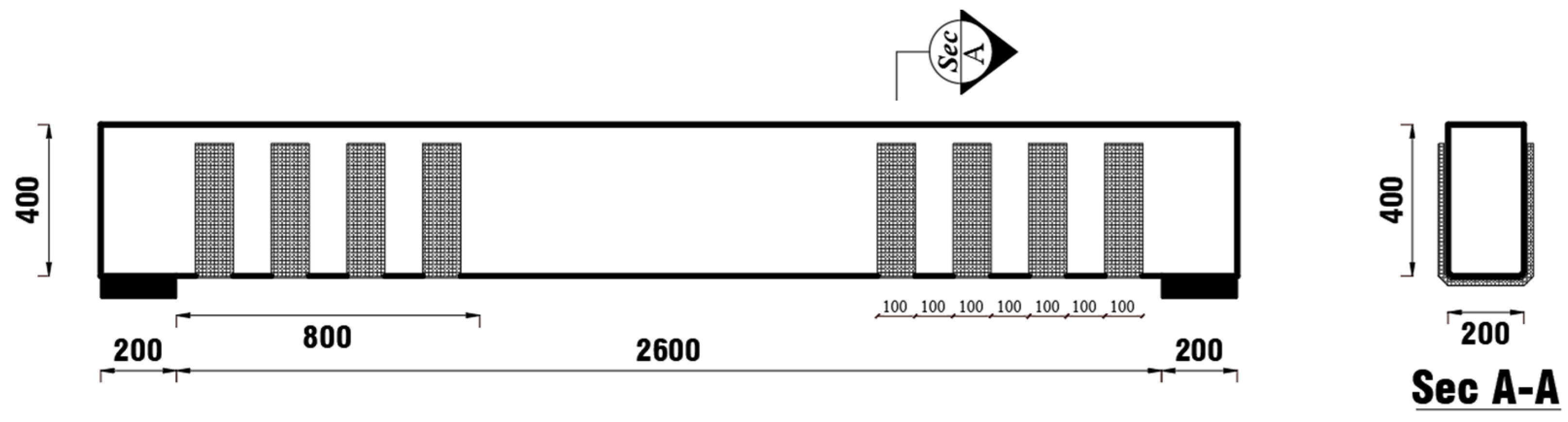
3. Preparation of Test Beams
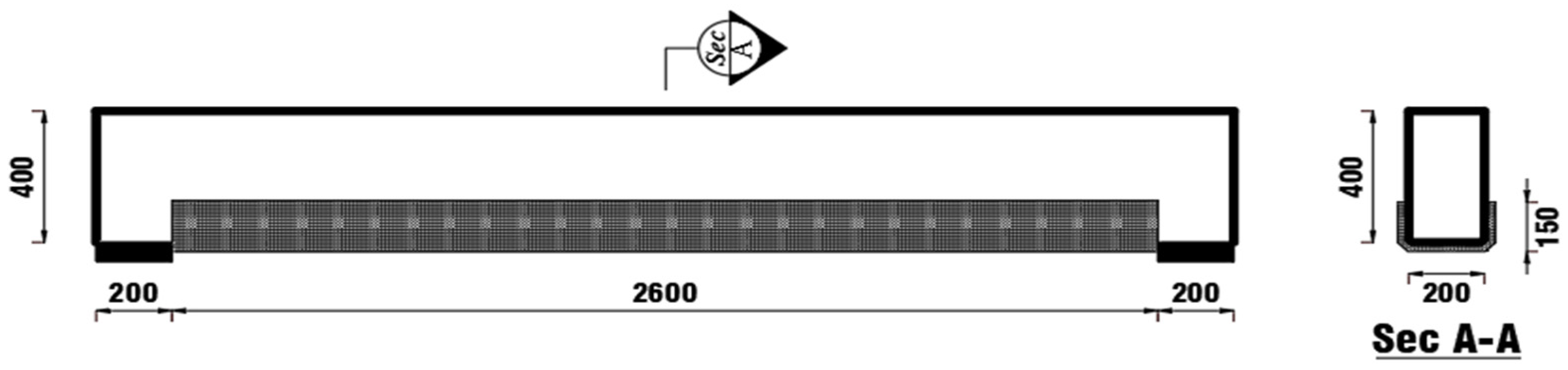
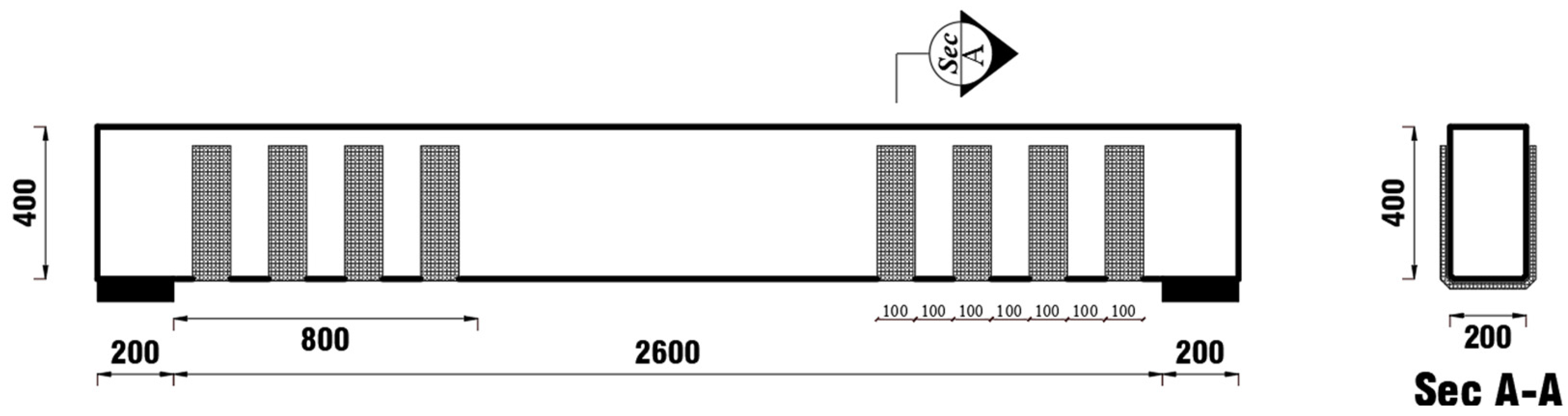
3.1. Strengthening by WCFF
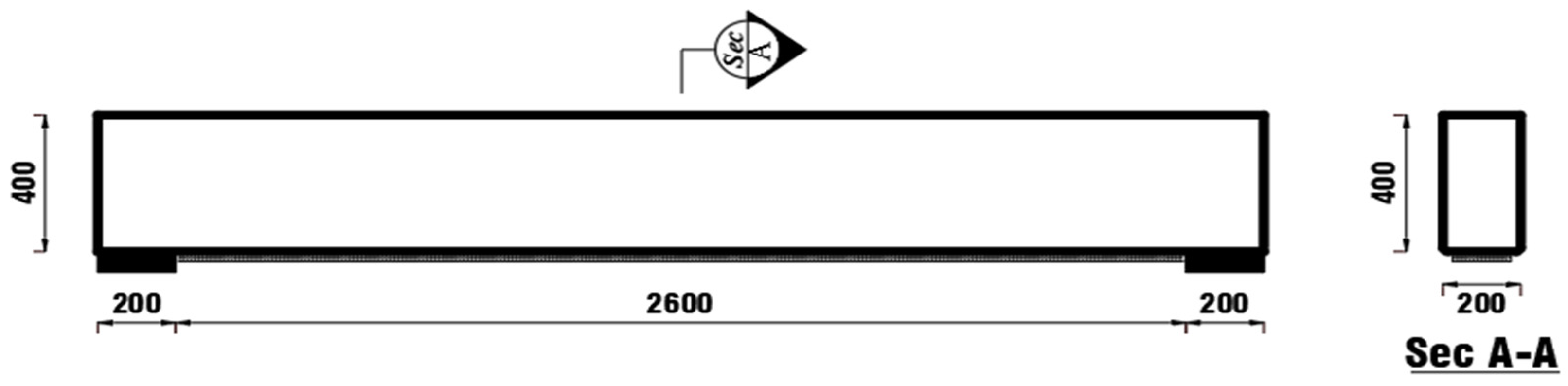
3.2. Strengthening by Steel Plates
4. Testing Procedure
5. Results and Discussion
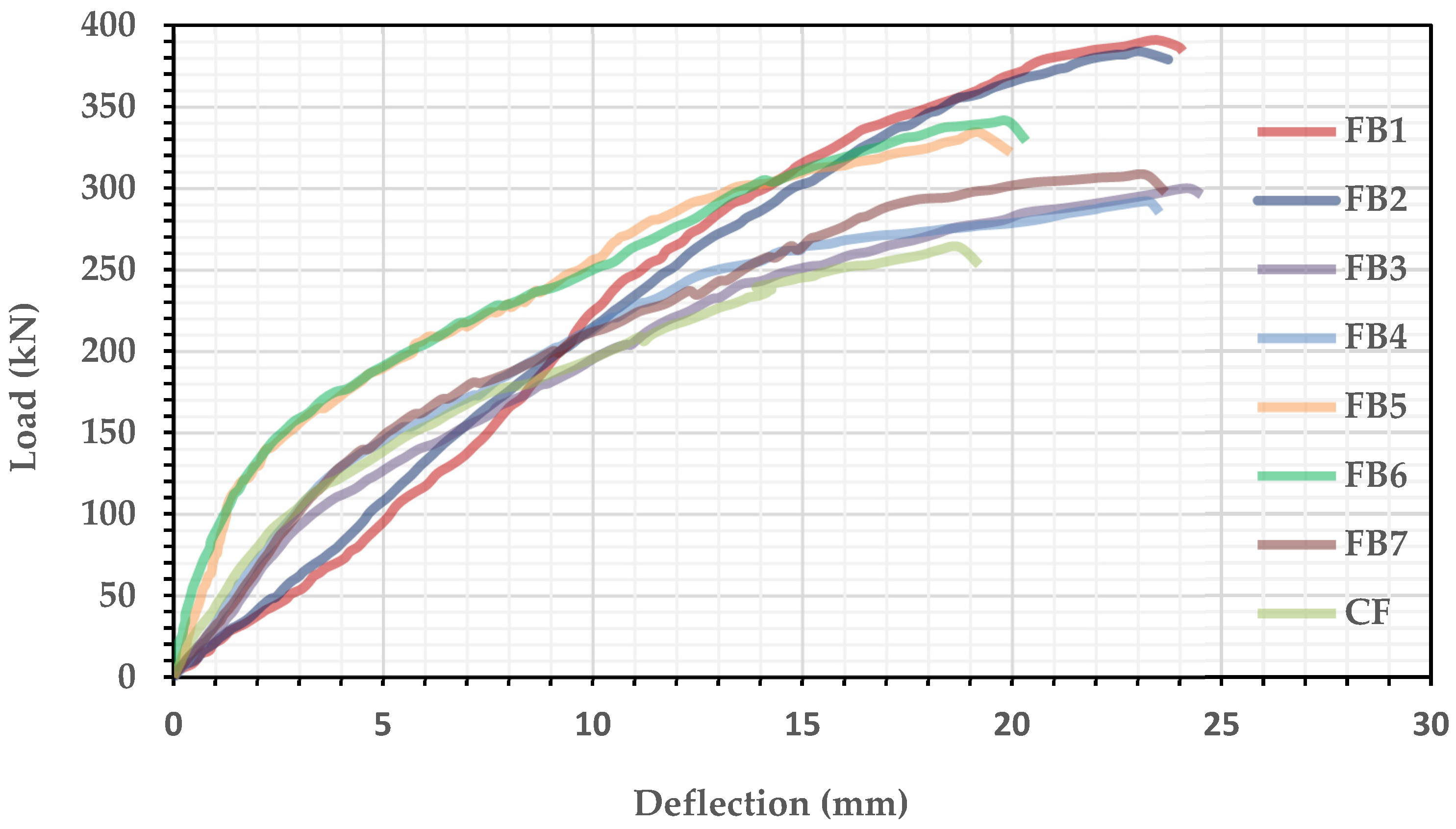
5.1. Flexural Test Series
5.1.1. Effect of Strengthening at Various Loads
5.1.2. Effect of Strengthening on Deflections
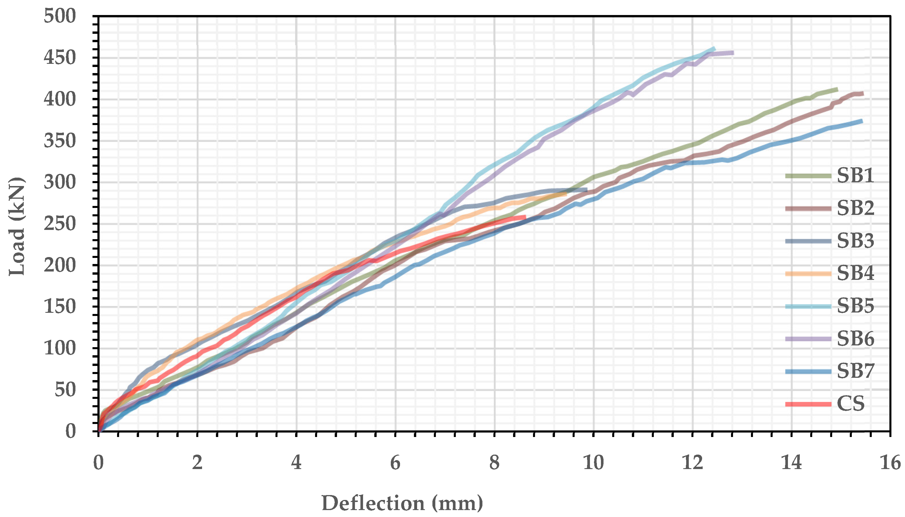
5.2. Shear Test Series
5.2.1. Effect of Strengthening at Various Loads
5.2.2. Effect of Strengthening on Deflections
6. Failure Modes and Cracking Patterns
7. Simulation Finite Element Model
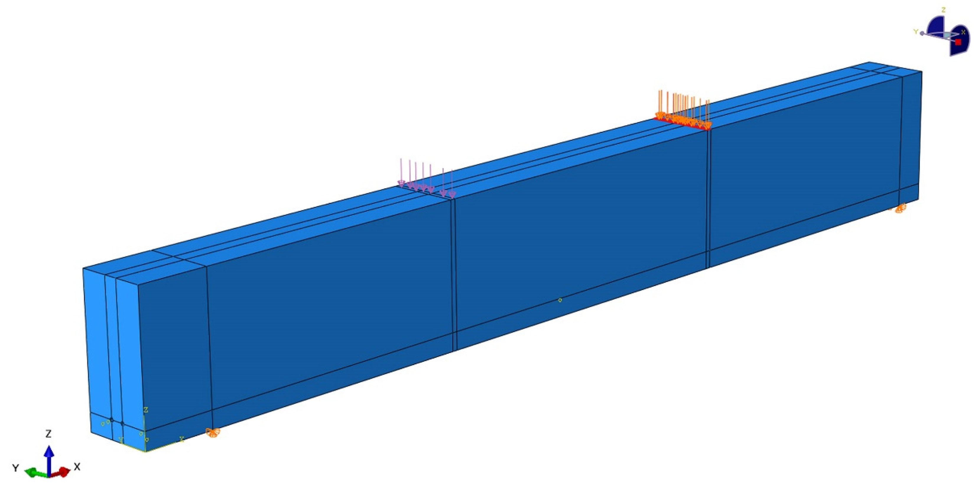
7.1. Finite Element Modeling
- Concrete beams were modeled using solid elements, specifically the C3D8R or brick elements.
- Reinforcement bars and stirrups were modeled using the T3D2 element, which represents truss elements. These elements were embedded in the concrete blocks.
- WCFF were modeled using conventional shell elements. Two types of shell elements were employed—S8R5 for thin-shell elements and S8R for thick-shell elements.
7.2. Material Modeling
- Concrete material model: The concrete damaged plasticity model available in Abaqus was employed to model concrete.
- Reinforcement bars: An elastic–plastic model was used to represent the reinforcement bars embedded in the concrete elements.
- Woven carbon fiber fabric (WCFF): An elastic-lamina model was used to simulate the WCFF.
7.3. Boundary Conditions
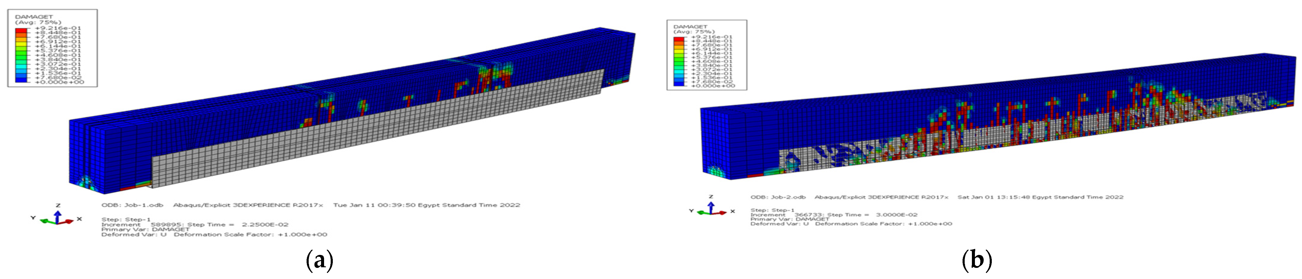
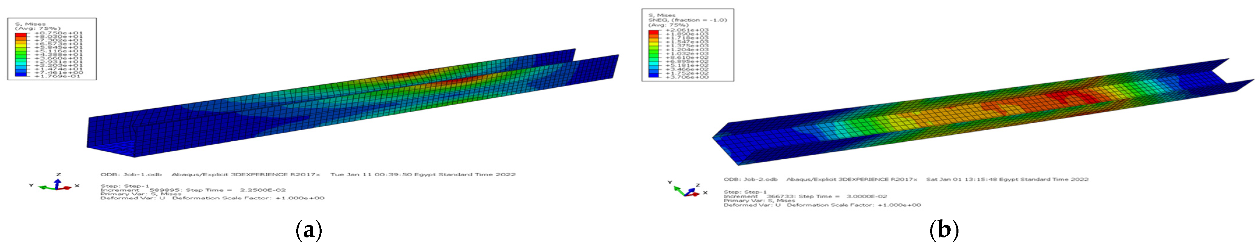
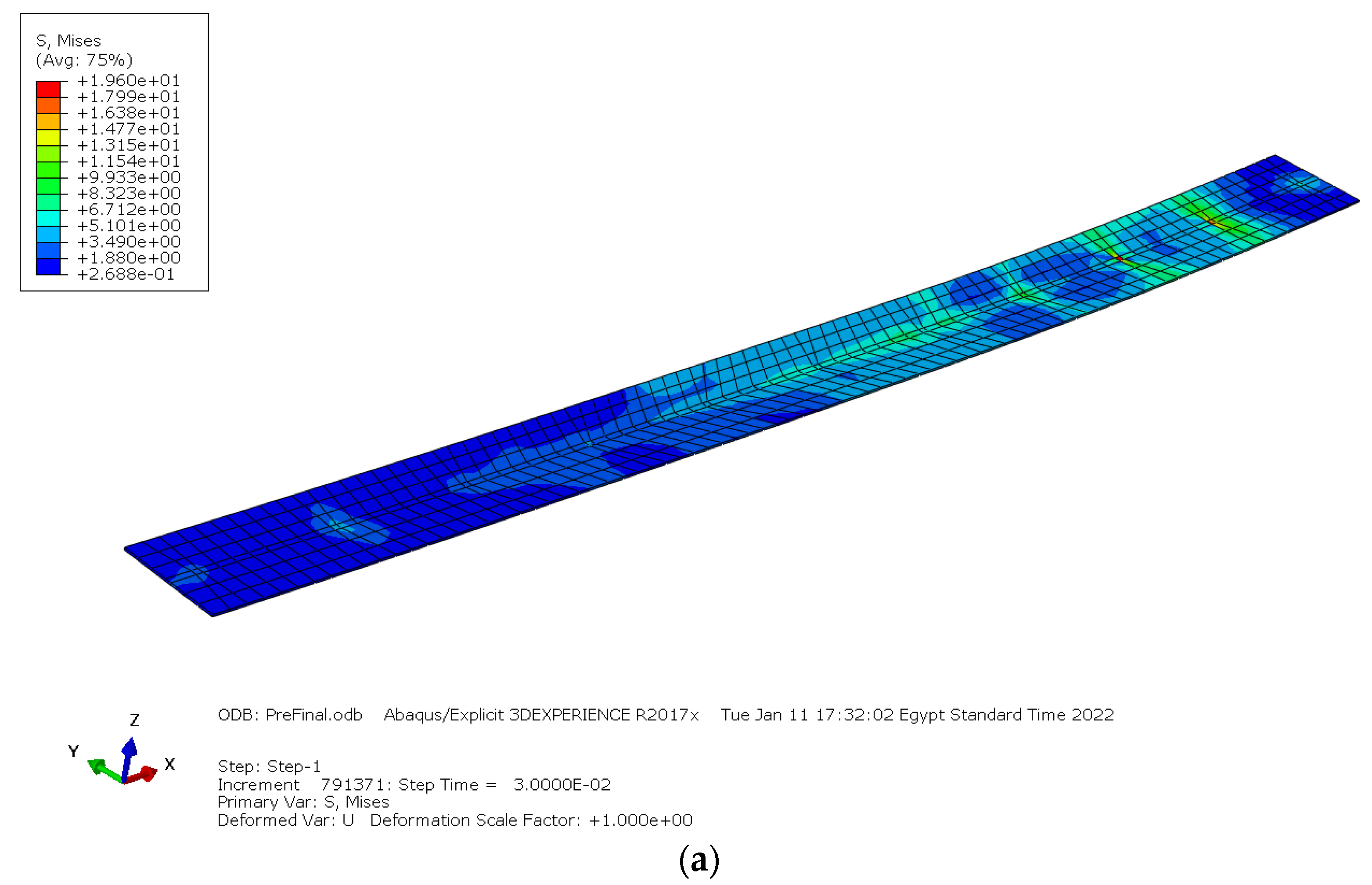
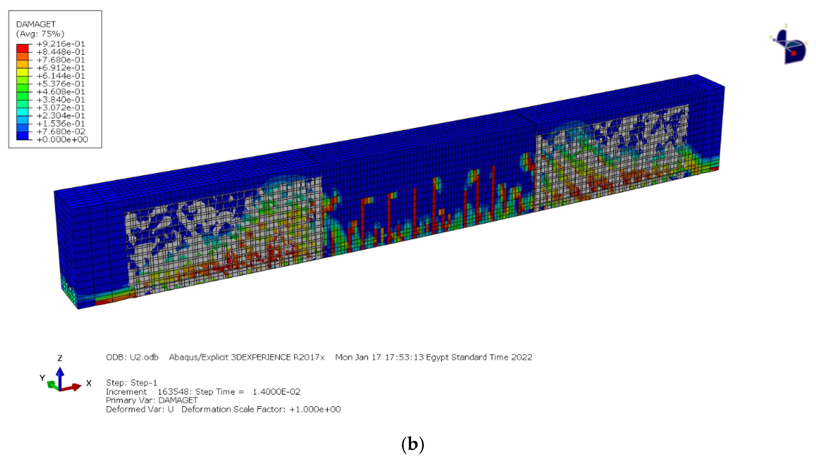
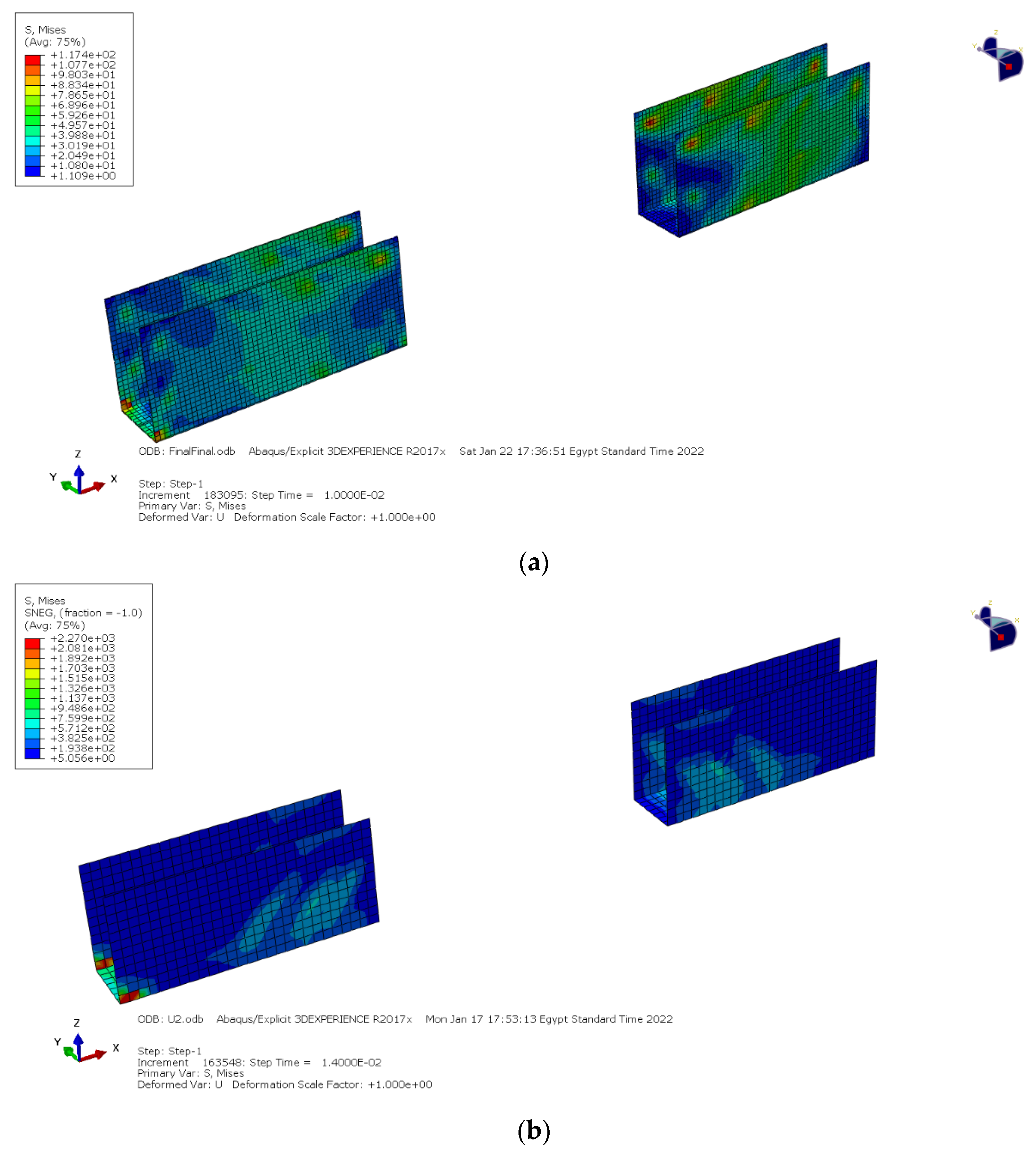
7.4. Finite Element Model Results for the Flexural Test Series
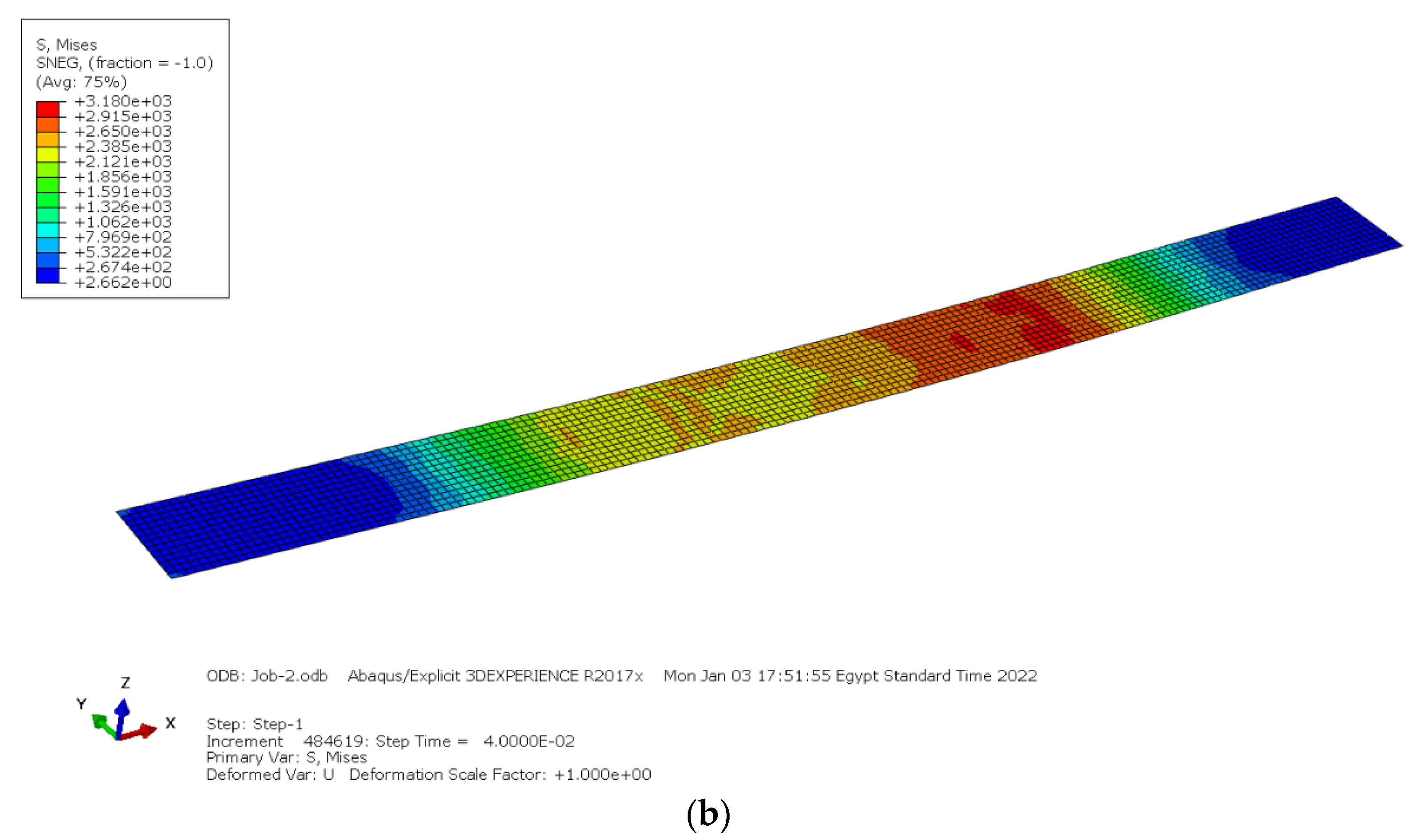
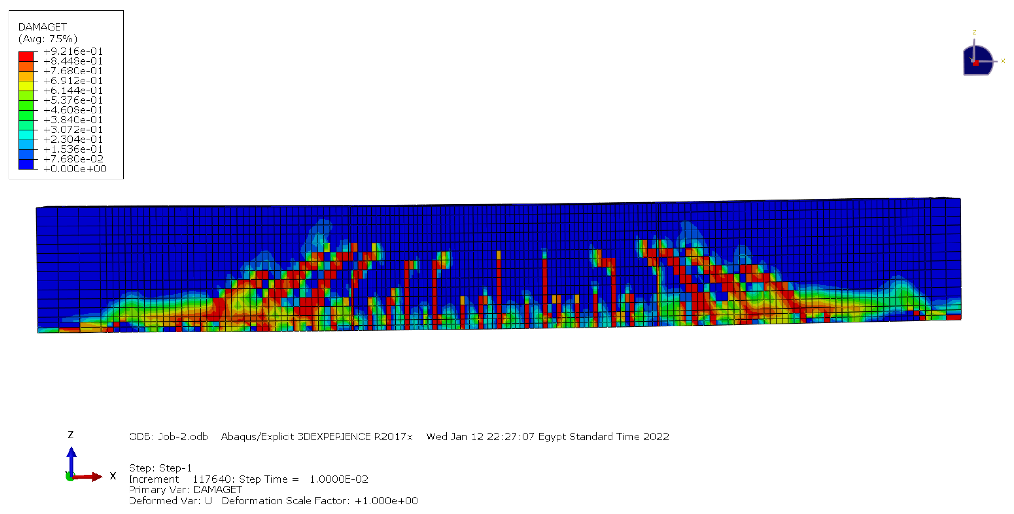
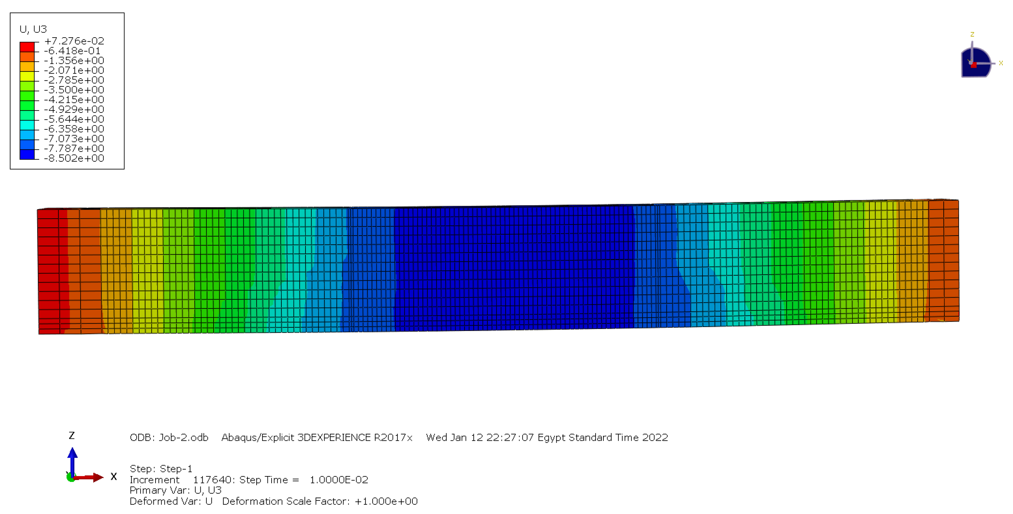
7.4.1. Control Beam (CF)
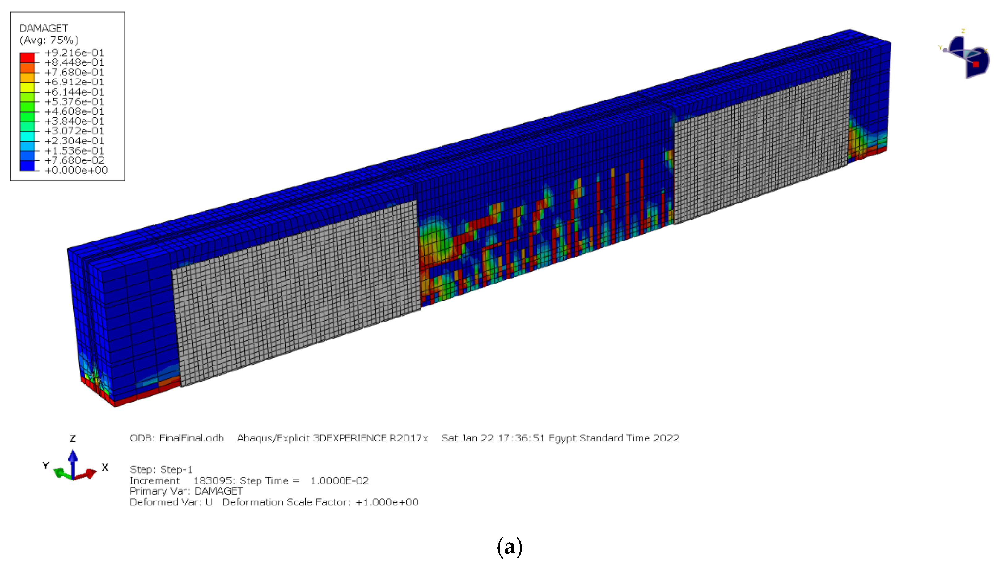
7.4.2. Addition of Steel Plate and WCFF (U-Shaped) to the Tension Side (FB1, FB5)
7.4.3. Addition of Steel Plate and WCFF to the Tension Side (FB3, FB7)
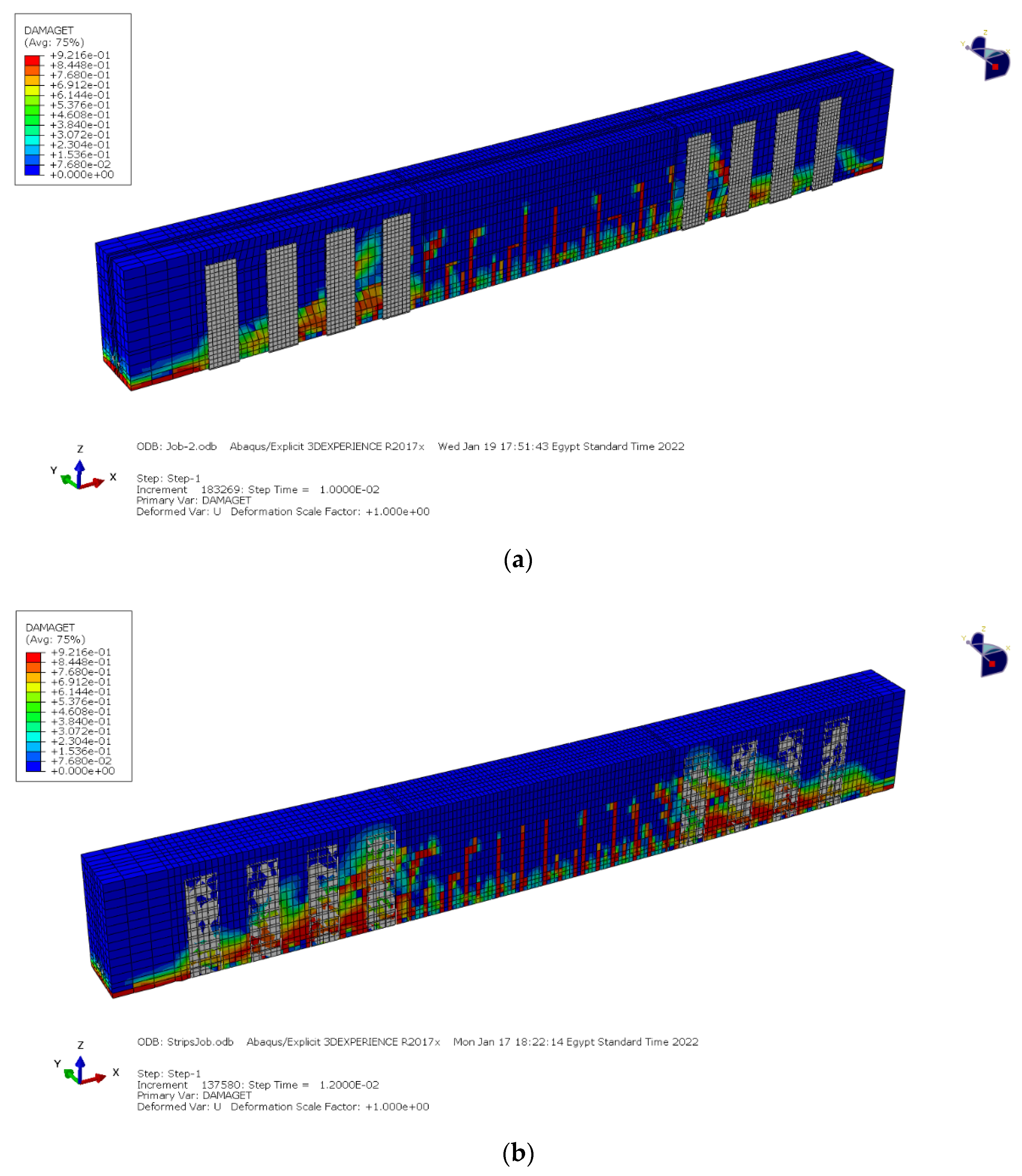
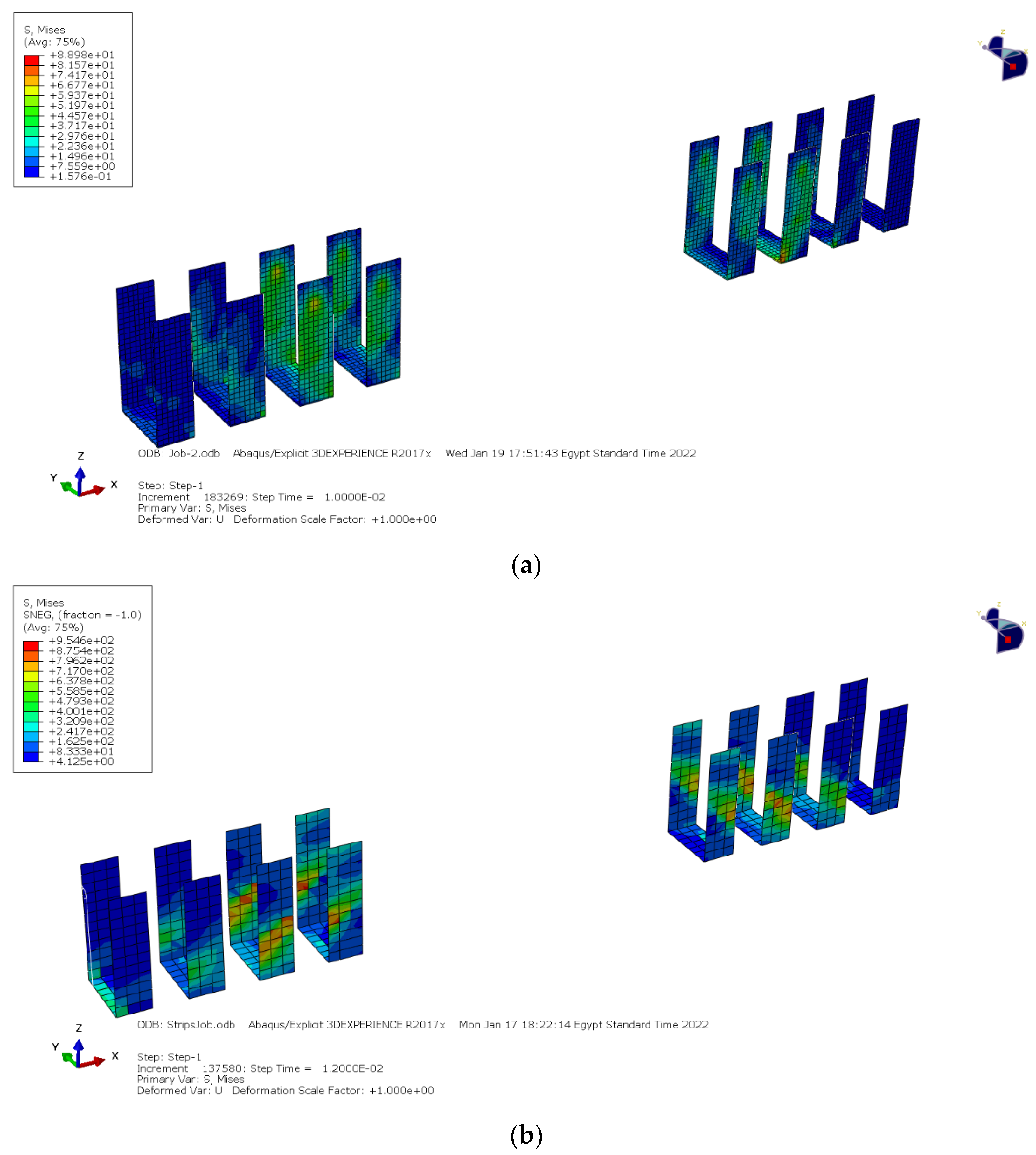
7.5. Finite Element Model Results for the Shear Test Series
7.5.1. Control Beam (CS)
7.5.2. Addition of Steel Plate and WCFF U-Shaped (SB1, SB5)
7.5.3. Addition of Steel Plate and WCFF Straps (SB3, SB7)
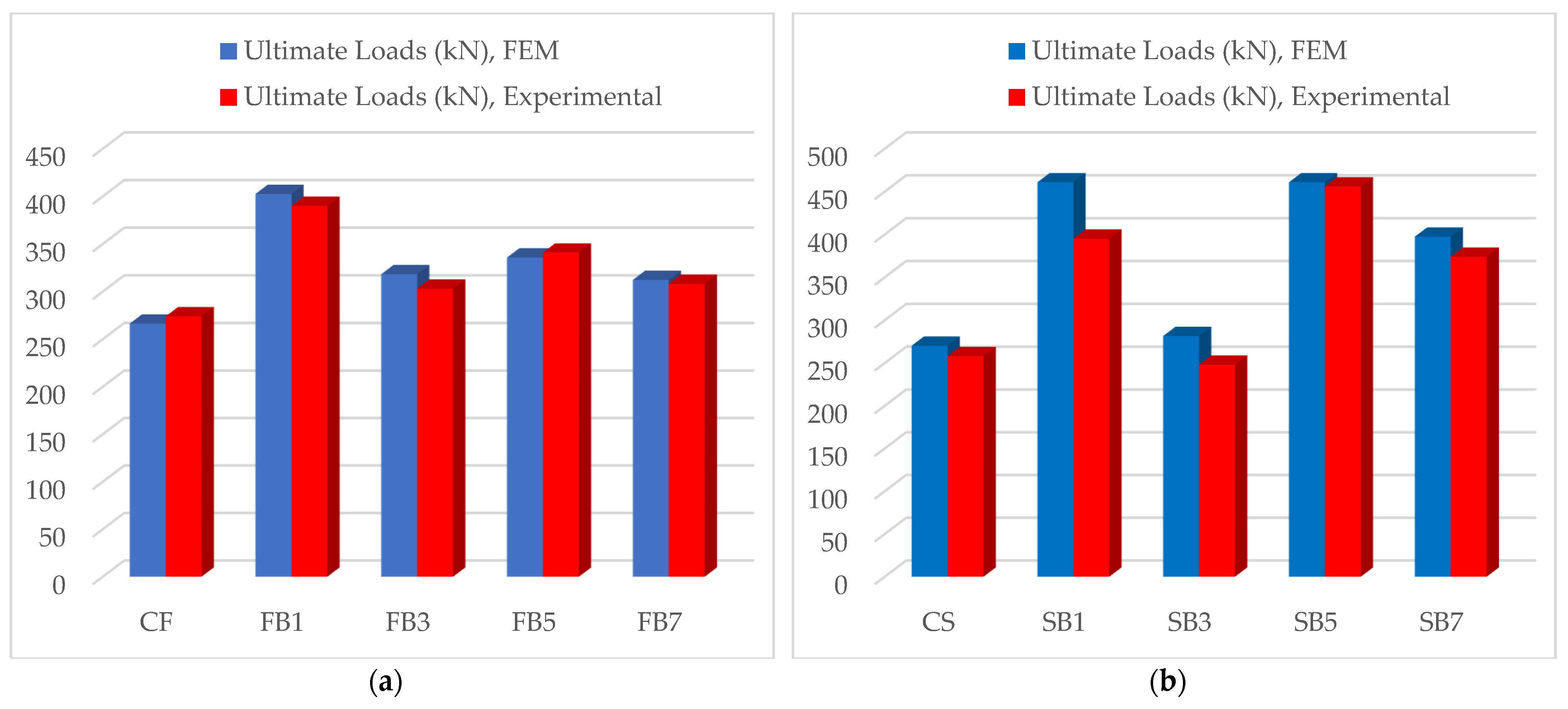
8. Comparison between FEM and Experimental Test Results
8.1. Ultimate Loads
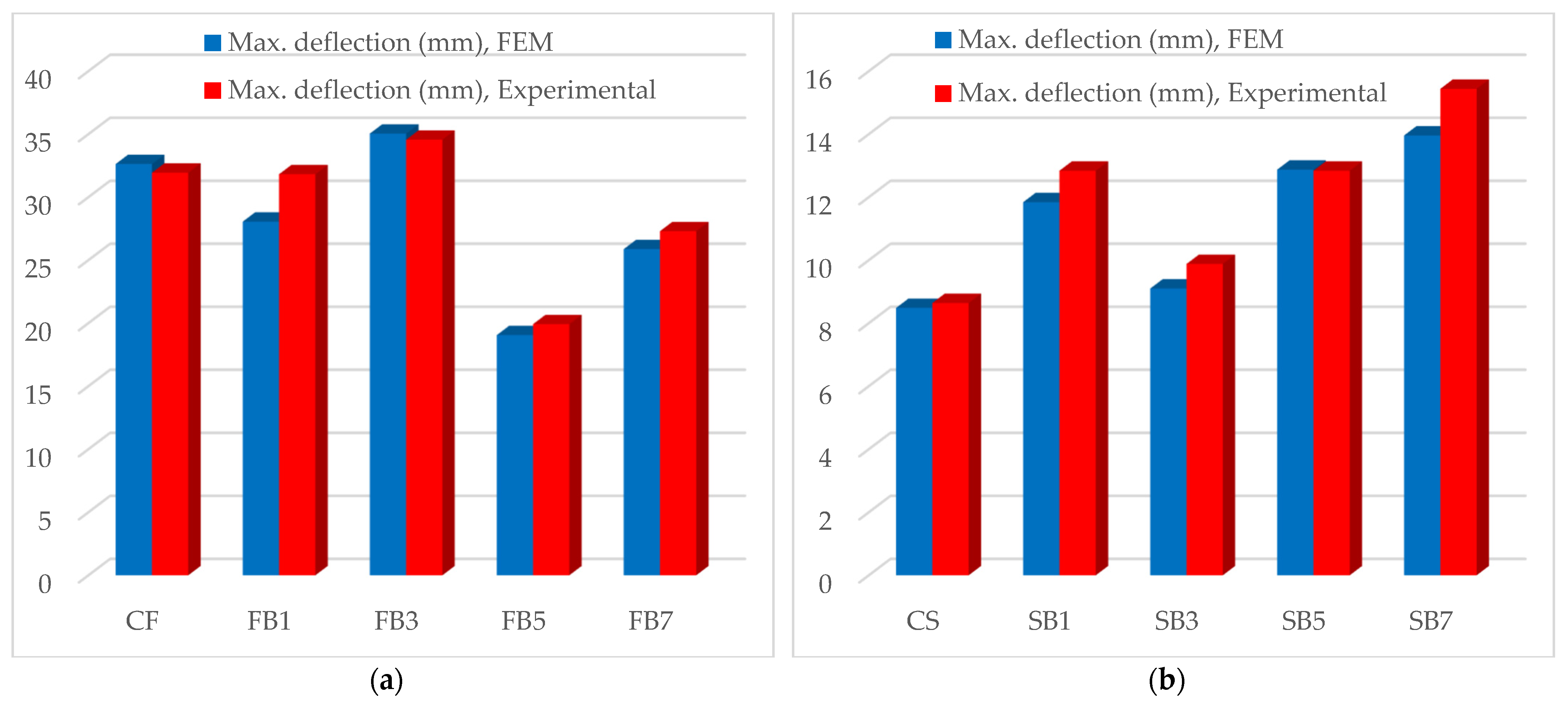
8.2. Max Deflection
9. Conclusions
- In summary, all strengthening techniques led to notable improvements in both flexural and shear strength outcomes when compared to the respective control beams. Specifically, the use of U-shaped steel plates resulted in significant increases between 57% and 97% in the first crack loads and between 14% and 48% in the ultimate loads for the prestressed concrete beams, strengthened with respect to their flexural properties. Likewise, woven carbon fiber fabric (WCFF) wrapping demonstrated increases between 27% and 35% in the first crack loads and between 17% and 29% in the ultimate loads.
- In terms of deflection, U-shaped steel plates and WCFF wrapping contributed to increases ranging from 25% to 29% and 27% to 38%, respectively, compared to the control beams.
- For prestressed concrete beams, strengthened with respect to their shear properties, the application of U-shaped steel plates yielded increases between 2% and 63% in the first crack loads and between 11% and 60% in the ultimate loads. WCFF wrapping, in turn, showed increases between 19% and 32% in the first crack loads and between 45% and 79% in the ultimate loads.
- Furthermore, the finite element model’s results demonstrated congruence with the experimental outcomes, affirming the efficacy of the presented model. Notably, the maximum difference in the ultimate load for the prestressed concrete beams, strengthened with respect to their flexural properties, was approximately 5%, and the mid-span deflection showed a variance of about 9%.
- Strengthening of pre-tension concrete beams could be carried out using more layers and angles of woven carbon fiber fabric (WCFF) wrapping.
- Strengthening of pre-tension concrete beams could be achieved using externally bonded hybrid fiber-reinforced polymer (HyFRP) laminates.
Author Contributions
Funding
Data Availability Statement
Acknowledgments
Conflicts of Interest
References
- Ravichandran, A.; Kothandaraman, S.; Zealakshmi, D. Flexural Behavior of Confined Hybrid Fiber in the Plastic Hinging Region of the High Strength Concrete Beam. Indian J. Sci. Technol. 2016, 9, 1–5. [Google Scholar]
- Ravichandran, A.; Kothandaraman, S.; Zealakshmi, D. Prediction of Flexural Performance of Confined Hybrid Fiber Reinforced High Strength Concrete Beam by Artificial Neural Networks. Indian J. Sci. Technol. 2016, 9, 1–6. [Google Scholar]
- Sim, C.; Tadros, M.; Gee, D.; Asaad, M. Flexural design of precast, prestressed ultra-high-performance concrete members. PCI J. 2020, 65, 35–61. [Google Scholar] [CrossRef]
- Lei, D.; Chen, G.; Chen, Y.; Ren, Q. Experimental research and numerical simulation of RC beams strengthened with bonded steel plates. Sci. China Technol. Sci. 2012, 55, 3270–3277. [Google Scholar]
- Al-Hassani, H.; Al-Ta’an, S.; Mohammed, A. Behavior of Damaged Reinforced Concrete Beams Strengthened with Externally Bonded Steel Plate. Tikrit J. Eng. Sci. 2013, 20, 48–59. [Google Scholar] [CrossRef]
- Daouadji, T.H. Analytical and numerical modeling of interfacial stresses in beams bonded with a thin plate. Adv. Comput. Des. 2017, 2, 57–69. [Google Scholar] [CrossRef]
- Altin, S.; Anil, Ö.; Kora, M.E. Improving shear capacity of existing RC beams using external bonding of steel plates. Eng. Struct. 2005, 27, 781–791. [Google Scholar] [CrossRef]
- Aykac, S.; Kalkan, I.; Uysal, A. Strengthening of reinforced concrete beams with epoxy-bonded perforated steel plates. Struct. Eng. Mech. 2012, 44, 735–751. [Google Scholar] [CrossRef]
- Alam, M.A.; Sami, A.; Mustapha, K.N. Embedded Connectors to Eliminate Debonding of Steel Plate for Optimal Shear Strengthening of RC Beam. Arab. J. Sci. Eng. 2017, 42, 4053–4068. [Google Scholar] [CrossRef]
- Esfahani, M.R.; Kianoush, M.R.; Tajari, A.R. Flexural behavior of reinforced concrete beams strengthened by CFRP sheets. Eng. Struct. 2007, 29, 2428–2444. [Google Scholar] [CrossRef]
- Rasheed, H.; Abdalla, J.; Hawileh, R.; Al-Tamimi, A. Flexural behavior of reinforced concrete beams strengthened with externally bonded Aluminum Alloy plates. Eng. Struct. 2017, 147, 473–485. [Google Scholar] [CrossRef]
- Abdalla, J.; Abu-Obeidah, A.; Hawileh, R.; Rasheed, H. Shear strengthening of reinforced concrete beams using externally-bonded aluminum alloy plates: An experimental study. Constr. Build. Mater. 2016, 128, 24–37. [Google Scholar] [CrossRef]
- Rakgate, S.M.; Dundu, M.S.M. Strength and ductility of simple supported R/C beams retrofitted with steel plates of different width-to-thickness ratios. Eng. Struct. 2018, 157, 192–202. [Google Scholar] [CrossRef]
- Askar, M.K.; Hassan, A.F.; Al-Kamaki, Y.S. Flexural and shear strengthening of reinforced concrete beams using FRP composites: A state of the art. Case Stud. Constr. Mater. 2022, 17, e01189. [Google Scholar] [CrossRef]
- Derkowski, A.; Walczak, R. Possibilities of increasing effectiveness of rc structure strengthening with frp materials. Materials 2021, 14, 1387. [Google Scholar] [CrossRef] [PubMed]
- Vijayan, D.S.; Revathy, J. Flexural Response of Fibre Reinforced Polymer Laminated Pre-stressed Concrete Beams. Indian J. Sci. Technol. 2016, 9, 1–6. [Google Scholar] [CrossRef]
- Hussien, O.F.; Elafandy, T.E.; Abdelrahman, A.S.; Abdel-Bakry, S.A.; Nasr, E.A. Behavior of bonded and unbonded prestressed normal and high strength concrete beams. Hous. Build. Natl. Res. Cent. J. 2012, 8, 239–251. [Google Scholar] [CrossRef]
- Revathy, J.; Saranya, S.; Illakkiya, B. Behavior of Prestressed Concrete Beams Strengthened with Externally Bonded Fiber Reinforced Polymer Laminates. Int. J. Struct. Anal. Des. 2014, 1, 60–64. [Google Scholar]
- Hurukadli, P.; Bharti, G.; Shukla, B.K. Behavior of fiber reinforced polymer laminates strengthening prestressed concrete beams. Mater. Today Proc. 2023, 78, 731–737. [Google Scholar] [CrossRef]
- Siddika, A.; Al-Mamun, M.d.A.; Ferdous, W.; Alyousef, R. Performances, challenges and opportunities in strengthening reinforced concrete structures by using FRPs—A state-of-the-art review. Eng. Fail. Anal. 2020, 111, 104480. [Google Scholar] [CrossRef]
- Dassault Systèmes. Abaqus User’s Guide; Dassault Systèmes: Velizy-Villacoublay, France, 2013. [Google Scholar]


| Sample | Strengthening Type | Connection Type |
|---|---|---|
| Flexural strengthening | ||
| CF | No strengthening (Control beam) | - |
| FB1, FB2 | Bottom steel plate (U-shape) | Anchors |
| FB3, FB4 | Bottom steel plate | Anchors |
| FB5, FB6 | Bottom WCFF (U-Shape) | Adhesive |
| FB7 | Bottom WCFF | Adhesive |
| Shear strengthening | ||
| CS | No strengthening (Control beam) | - |
| SB1, SB2 | Steel plate (U-shape) | Anchors |
| SB3, SB4 | Steel plate (Straps) | Anchors |
| SB5, SB6 | WCFF (U-Shape) | Adhesive |
| SB7 | WCFF (Straps) | Adhesive |
| Specimen ID | Average Cube Compressive Strength after 7 Days (MPa) | Average Cube Compressive Strength after 28 Days (MPa) |
|---|---|---|
| SB1 | 25.9 | 38.6 |
| SB2 | 25.6 | 35.6 |
| SB3 | 27.8 | 40.8 |
| Reinf. | Bar Dia. (mm) | Plate Thick. (mm) | Yield Stress (MPa) | Ult. Stress (MPa) | Modulus of Elasticity (MPa) |
|---|---|---|---|---|---|
| Steel Bars | 8 | - | 470 | 575 | 210,000 |
| 10 | - | 450 | 550 | 211,000 | |
| 12 | - | 440 | 530 | 207,000 | |
| 18 | - | 490 | 581 | 200,000 | |
| 22 | - | 492 | 595 | 205,000 | |
| Steel Plate | - | 4 | 345 | 420 | 206,000 |
| Diameter (mm) | Tensile Strength (MPa) | Mass (g/m) | Cross-Sectional Area (mm2) | Minimum Breaking Strength (kN) | Maximum Breaking Strength (kN) |
|---|---|---|---|---|---|
| 12.5 | 1860 | 726.3 | 93.0 | 173.0 | 199.0 |
| Thickness (mm) | Fiber Density (g\cm3) | Tensile Strength (MPa) | Ultimate Elongation (%) | Elasticity Modulus (MPa) |
|---|---|---|---|---|
| 0.131 | 1.76 | 4300 | 1.8 | 238,000 |
| No. | Specimen | F.C.L (kN) | Deflection of F.C.L (mm) | Maximum Load (kN) | Deflection of Maximum Load (mm) | Strengthening Type | Connection Type |
|---|---|---|---|---|---|---|---|
| 1 | CF | 58 | 1.40 | 264 | 18.74 | (Control beam) | - |
| 2 | FB1 | 110 | 2.84 | 391 | 23.46 | Bottom steel plate (U-shape) | Anchors |
| 3 | FB2 | 114 | 2.90 | 384 | 23.06 | ||
| 4 | FB3 | 91 | 1.99 | 300 | 24.18 | Bottom steel plate | Anchors |
| 5 | FB4 | 92 | 2.02 | 292 | 23.24 | ||
| 6 | FB5 | 77 | 0.90 | 334 | 19.25 | Bottom WCFF (U-Shape) | Adhesive |
| 7 | FB6 | 78 | 0.92 | 341 | 19.92 | ||
| 8 | FB7 | 74 | 1.3 | 308.2 | 23.2 | Bottom WCFF | Adhesive |
| No. | Specimen | F.C.L (kN) | Deflection of F.C.L (mm) | Maximum Load (kN) | Deflection of Maximum Load (mm) | Strengthening Type | Connection Type |
|---|---|---|---|---|---|---|---|
| 1 | CS | 112 | 1.74 | 258 | 2.9 | (Control beam) | - |
| 2 | SB1 | 182 | 2.65 | 412 | 14.94 | Steel plate (U-Shape) | Anchors |
| 3 | SB2 | 175 | 2.32 | 407 | 15.46 | ||
| 4 | SB3 | 120 | 2.73 | 291 | 9.88 | Steel plate (Straps) | Anchors |
| 5 | SB4 | 114 | 2.44 | 286 | 9.46 | ||
| 6 | SB5 | 148 | 2.26 | 462 | 12.46 | WCFF (U-Shape) | Adhesive |
| 7 | SB6 | 144 | 2.29 | 456 | 12.84 | ||
| 8 | SB7 | 133 | 1.79 | 374 | 15.44 | WCFF (Straps) | Adhesive |
| Parameter | Model (1) | Model (2) | Model (3) |
|---|---|---|---|
| Mass density, kg/m3 | 2400 | 2400 | 2400 |
| Modulus of elasticity (Es), MPa | 17,864 | 22,736.58 | 23,424.77 |
| Poisson’s ratio (υ) | 0.14 | 0.16 | 0.17 |
| Parameter | Dilation Angle | Eccentricity | fb0/fc0 | K | Viscosity p. |
|---|---|---|---|---|---|
| Model (1) | 41 | 0.8 | 1.16 | 0.667 | 0.000001 |
| Model (2) | 49 | 0.04 | 1.18 | 0.667 | 0.000001 |
| Model (3) | 37 | 0.1 | 1.16 | 0.667 | 0.000001 |
| Parameter | High Tensile | Normal–Mild |
|---|---|---|
| Mass density, kg/m3 | 7859 | 7859 |
| Modulus of elasticity (Es), MPa | 210,000 | 203,000 |
| Poisson’s ratio (υ) | 0.3 | 0.3 |
| Yield stress, MPa | 490 | 470 |
| Ultimate stress, MPa | 581 | 575 |
| Elongation, % | 15 | 23 |
| Parameter | WCFF |
|---|---|
| Mass density, kg/m3 | 1760 |
| Modulus of elasticity (E1), MPa | 238,000 |
| Modulus of elasticity (E2), MPa | 238,000 |
| Poisson’s ratio (Nu12) | 0.23 |
| Shear modulus (G12), MPa | 7800 |
| Shear modulus (G13), MPa | 7800 |
| Shear modulus (G23), MPa | 7800 |
| Stress limit (tensile strength), MPa | 4300 |
| Thickness, mm | 0.131 |
Disclaimer/Publisher’s Note: The statements, opinions and data contained in all publications are solely those of the individual author(s) and contributor(s) and not of MDPI and/or the editor(s). MDPI and/or the editor(s) disclaim responsibility for any injury to people or property resulting from any ideas, methods, instructions or products referred to in the content. |
© 2023 by the authors. Licensee MDPI, Basel, Switzerland. This article is an open access article distributed under the terms and conditions of the Creative Commons Attribution (CC BY) license (https://creativecommons.org/licenses/by/4.0/).
Share and Cite
Eisa, A.S.; Kotrasova, K.; Sabol, P.; Mihaliková, M.; Attia, M.G. Experimental and Numerical Study of Strengthening Prestressed Reinforced Concrete Beams Using Different Techniques. Buildings 2024, 14, 29. https://doi.org/10.3390/buildings14010029
Eisa AS, Kotrasova K, Sabol P, Mihaliková M, Attia MG. Experimental and Numerical Study of Strengthening Prestressed Reinforced Concrete Beams Using Different Techniques. Buildings. 2024; 14(1):29. https://doi.org/10.3390/buildings14010029
Chicago/Turabian StyleEisa, Ahmed S., Kamila Kotrasova, Peter Sabol, Mária Mihaliková, and Mohamed G. Attia. 2024. "Experimental and Numerical Study of Strengthening Prestressed Reinforced Concrete Beams Using Different Techniques" Buildings 14, no. 1: 29. https://doi.org/10.3390/buildings14010029