Article

Experimental Study on the Evolution Law of the Mechanical and Pore Characteristic Parameters of Set Cement under High- and Ultra-High-Temperature Treatments

1
Faculty of Architecture, Civil and Transportation Engineering, Beijing University of Technology, Beijing 100124, China
2
CNPC Xibu Drilling Engineering Company Limited, Karamay 834000, China
3
National Engineering Research Center for Oil and Gas Drilling and Completion Technology, Daqing 163311, China
4
Daqing Drilling and Exploration Engineering Company, Daqing 163311, China
*
Author to whom correspondence should be addressed.
Buildings 2024, 14(1), 303; https://doi.org/10.3390/buildings14010303
Submission received: 18 December 2023 / Revised: 7 January 2024 / Accepted: 19 January 2024 / Published: 22 January 2024

Abstract

:
Cement has been widely used as a structural material in many underground projects, and these projects often face high- or ultra-high-temperature environments, leading to the deterioration of the mechanical, porosity, and permeability properties of set cement, thereby increasing the risk of instability of underground structures. In response to this, two new temperature-resistant cement slurry systems were designed. Experiments were conducted on the changes in porosity and permeability of set cement after thermal treatment using low-field nuclear magnetic resonance technology (NMR), visual studies of pore and crack development were carried out using the argon-ion polishing field emission scanning electron microscopy (FE-SEM) and computed tomography (CT) methods. The research results show that as the thermal treatment temperature continued to rise, the compressive strength first increased (25 °C–200 °C) and then decreased (200 °C–600 °C). The porosity of the set cement first decreased (25 °C–115 °C) and then increased (115 °C–600 °C), and the penetration first slowly increased (25 °C–400 °C) and then rapidly increased (400 °C–600 °C). Visualization experiments were conducted on micro-cracks and the pore distribution of the set cement under high- and ultra-high-temperatures, which proved the evolution law of these characteristic parameters. The research results have vital reference significance for the protection of the structural stability of cement components when encountering high-temperature environments.

1. Introduction

Cement has been widely used as a structural material in many underground projects such as tunnel construction, deep underground landfills of nuclear waste, geothermal energy development, underground coal gasification, and oil shale pyrolysis [1,2,3,4,5]. Considering that these projects often face high-temperature challenges, such as fires encountered during tunnel construction, temperature increases caused by nuclear waste heat release, high-temperature environments during geothermal energy development, and heat treatment during the in situ thermal recovery of oil shale, the mechanical properties of set cement will be challenged [6,7,8]. In addition, in high-temperature environments, the porosity and permeability parameters of cementitious materials can deteriorate. Under the action of external fluids such as formation water or corrosive gases, their mechanical properties can accelerate and deteriorate, leading to rapid declines in their compressive strength and support capacity, increasing the risk of building or structural instability [9,10,11,12]. Therefore, exploring the changes in mechanical properties, porosity, and permeability characteristics of cement paste at high temperatures can provide a theoretical basis for evaluating the risk of structural instability in cement under high-temperature conditions, which is of great significance.
A series of studies have been conducted by previous researchers on the changes in the mechanical properties of cement paste under high temperatures [13,14,15,16,17,18]. Some scholars mainly conducted indoor experiments to test and analyze the changes in mechanical parameters such as compressive strength, tensile strength, and elastic modulus under high-temperature conditions with different heat treatment temperatures. The research results show that the higher the heat treatment temperature, the higher the degree of degradation of these mechanical parameters [19,20,21]. At the same time, Lin et al. (2020) and Zhang et al. (2022) also pointed out that in different engineering scenarios, the heating rate, cooling method, etc. also have an impact on the damage of set cement, and once the heat treatment temperature exceeds 400 °C, the degradation rate of set cement will be significantly accelerated. In addition, under the action of high temperature, the porosity and permeability of cement paste will also continuously increase. This is mainly because high temperature increases the internal thermal stress of cement paste, leading to the continuous development of internal pores and the generation of micro-cracks [22,23,24,25]. From this, it can also be seen that designing and developing a high-temperature-resistant cement slurry is extremely important for ensuring the mechanical properties of cement paste at high temperatures.
The above study conducted a series of studies on the integrity damage of set cement under high-temperature conditions. However, many aspects are still not fully considered, mainly reflected in the following two aspects. (1) Insufficient analysis of the impact of extreme temperatures at ultra-high temperatures in previous studies [26,27,28,29]. For example, in underground energy extraction projects, in view of the late appearance of shale oil in situ pyrolysis mining, previous research mainly considered the high-temperature effect of heavy oil thermal recovery. The ultimate ambient temperature set via theoretical analysis or indoor testing was usually below 350 °C. However, for shale oil in situ pyrolysis mining, the heating temperature should be set to or even exceed 500 °C to ensure that the kerogen in the oil shale can transform from a solid to gaseous state and form oil and gas migration paths in the tight shale matrix. In this regard, few studies have considered the changes in the mechanical properties, failure mode, porosity, and permeability of the set cement under corresponding ultra-high-temperature conditions. (2) Insufficient analysis of the impact of high-temperature heat treatment on the integrity of set cement. The integrity of set cement requires consideration of the influence of porosity and permeability changes on the fluid seepage-formation process, as well as the generation and development of cracks in the set cement under the high-temperature effect [30,31]. In response to this, it is urgent to develop a new type of cement slurry system and conduct research on the mechanical properties, porosity, and permeability changes in set cement under high- and ultra-high-temperature conditions to evaluate the integrity of the cement structure under high- and ultra-high-temperature conditions.
This study considered the thermal treatment temperature conditions (200 °C–600 °C) in a wellbore during the in situ pyrolysis mining of shale oil, and two new temperature-resistant cement slurry systems were designed. Experiments were conducted on the changes in the mechanical properties of set cement under different temperature thermal treatment conditions and different confining pressures, and the changes in the porosity and permeability of set cement after thermal treatment were measured using low-field nuclear magnetic resonance technology (NMR). Visual studies of pore and crack developments under high- and ultra-high-temperature conditions were carried out using the argon-ion polishing field emission scanning electron microscopy (FE-SEM) method. Computed tomography (CT) scanning technology was also used to visualize and analyze the changes in pore distribution after heat treatment. The research results have vital reference significance for the protection of the structural stability of cement components when encountering high-temperature environments and optimizing the high-temperature-resistant cement slurry formula.

2. Materials and Methods

2.1. Subsection

Two cement slurry systems were designed and configured considering the thermodynamic environment during underground building fires. The 1# cement slurry system configuration was as follows: Solid additives are G-grade cement + sand + expansion agent + toughening agent, dry powder instant water loss reducer fluid reagent was added in the cement slurry, and the water–cement ratio was 0.53. The 2# cement slurry system configuration was as follows: Solid additives are G-grade cement + sand + expansion agent, clean water was added to the cement slurry, and the water–cement ratio was 0.52.
The configured cement slurry was injected into a mold for curing. The internal dimensions of the mold were 25 mm × 50 mm. The curing pressure and temperature were set to 20.7 MPa and 115 °C, and the curing time was seven days. After curing and molding, both ends of the specimen were polished to ensure the surface flatness was within 0.05 mm, as presented in Figure 1.

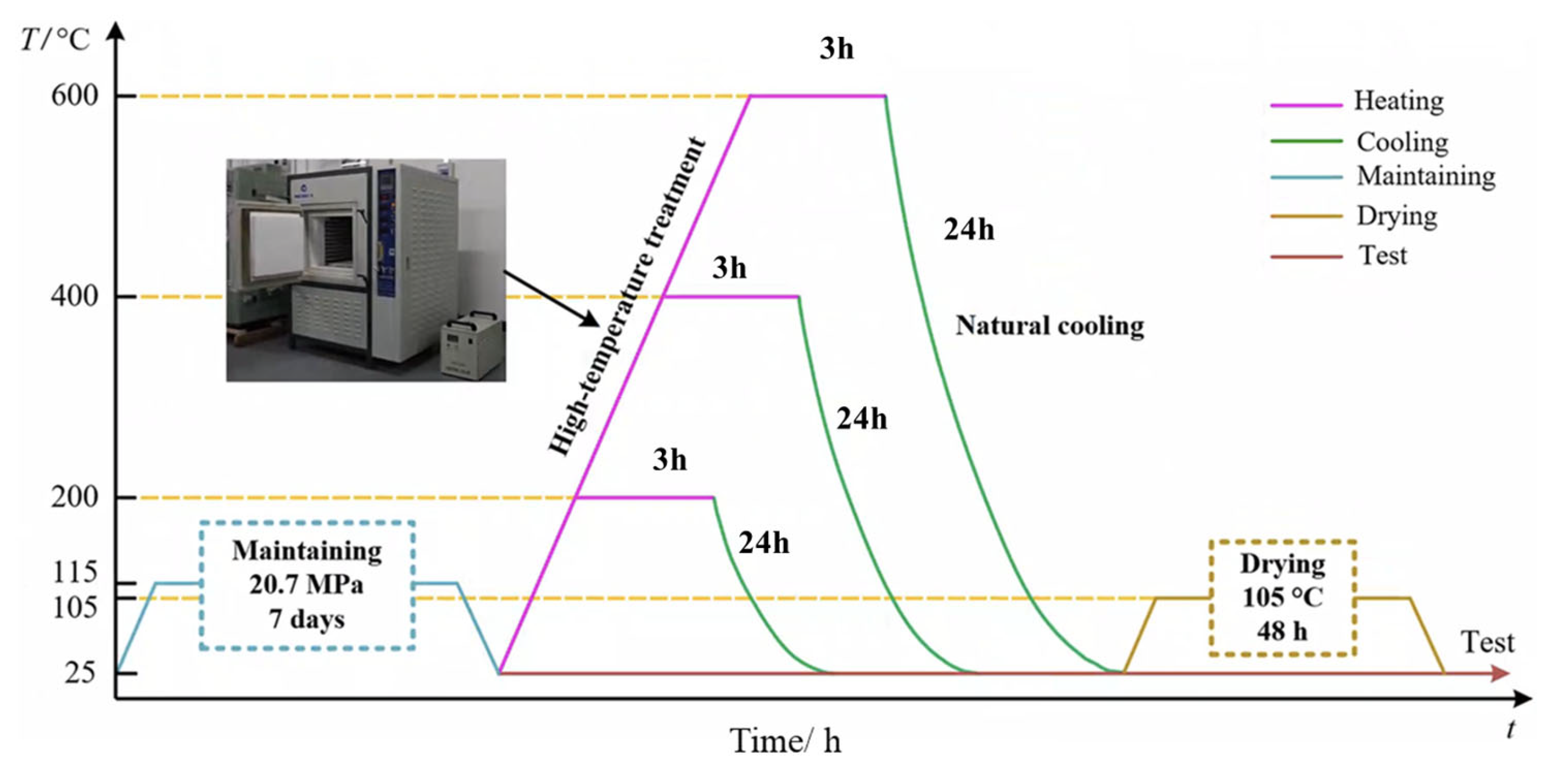
2.2. Experimental Methodology

In underground engineering, especially in the field of oil and gas engineering, the definition of bottomhole high temperature is above 150 °C but below 205 °C, and ultra-high temperature and above are above 205 °C. Considering the actual situation of set cement bearing high- and ultra-high-temperature loads during underground building fires, the cured specimens were subjected to thermal treatment. Model MXQ1200-50 heating equipment was selected, with a heating temperature of 1200 °C and accuracy of ±1 °C. Before the beginning of the thermal treatment, all specimens were divided into five groups, each containing 16 specimens. Taking the set cement specimens at room temperature (25 °C) as the control group, the other four groups of specimens were heated to 115 °C, 200 °C, 400 °C, and 600 °C, respectively.
According to previous research results, the heating rate also specifically impacts rock damage. As a result, each specimen group was heated to the target temperature at a constant speed of 2.5 °C/min, ensuring that all parts in the test block were evenly heated. Moreover, the continuous temperature was maintained for 180 min to guarantee that the set cement was sufficiently heated [32]. Then, the thermal treatment specimens were naturally cooled for 24 h. Considering that the moisture content of the specimens may affect the NMR measurement results, all samples were dried at 105 °C for 48 h before returning to room temperature. The heating process is displayed in Figure 2.

2.3. Subsection

There were a total of 80 samples, including 16 samples at each heat treatment temperature (25 °C, 115 °C, 200 °C, 400 °C, and 600 °C). For each thermal treatment temperature, there were 16 test samples used to conduct the following four types of tests, with four samples for each experiment (Figure 3):
(1) Mechanical characteristic experiments under confining pressure conditions. Considering that set cement has to withstand the combined effects of the structural internal stress and crustal stress underground, mechanical characteristic experiments under confining pressure conditions were performed, and then the compressive strength of the set cement under different heat treatment conditions was obtained.
(2) Experiment on pore size and distribution based on low-field nuclear magnetic resonance technology. Before the experiment, the specimens were placed in a vacuum-pressurized saturation device for 12 h to reach a 100% water-saturated state, and then the samples were placed in a low-field nuclear magnetic resonance experimental device. Through inversion calculation, T2 spectra in the water-saturated state were obtained, and the pore size distribution, porosity, and permeability could be calculated based on this.
(3) Argon-ion polishing field emission-scanning electron microscopy (FE-SEM) was employed to feature the microscopic pore structure properties of the set cement. Each specimen was subjected to argon-ion polishing and then heated to 115 °C, 200 °C, 400 °C, and 600 °C, respectively. The developments of pores and cracks in the samples at exact locations were noted.
(4) A computer tomography (CT) scanning experiment was conducted to analyze the changes in pores in three dimensions. Each specimen was first scanned at room temperature, and then the specimens were heated to 115 °C, 200 °C, 400 °C, and 600 °C, respectively. The change patterns of the pore size distributions in the specimens were observed.

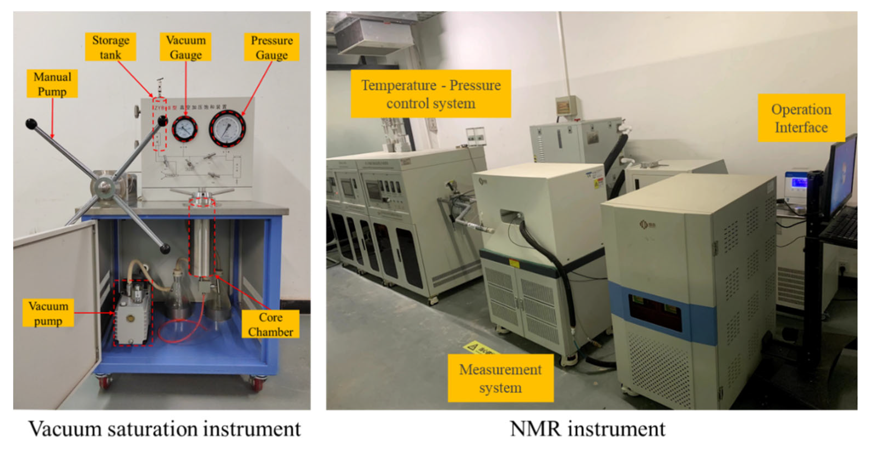
2.3.1. NMR Experiments

Nuclear magnetic resonance (NMR) technology can be used to measure and analyze the size and distribution of pores before and after thermal treatment. When testing porous media samples, the hydrogen nucleus signal of the selection itself can be measured, and parameters related to the physical properties (such as saturation, porosity, and permeability) could be obtained [33]. In this paper, the instrument used in the nuclear magnetic resonance experiment was a Micro MR12-025V LF NMR analyzer (Figure 4). The laboratory temperature was constant at 25.00 ± 0.50 °C. The magnetic field temperature was controlled at 32.00 ± 0.02 °C. An NMR frequency of 12 MHz and a probe coil diameter of 25 mm were used. The test sequence adopted the CPMG sequence. The main parameters were as follows: echo interval (TE) = 0.1 ms, sampling interval (TW) = 3000 ms, number of echoes (NECH) = 8000, and cumulative sampling number (NS) = 128 [34].

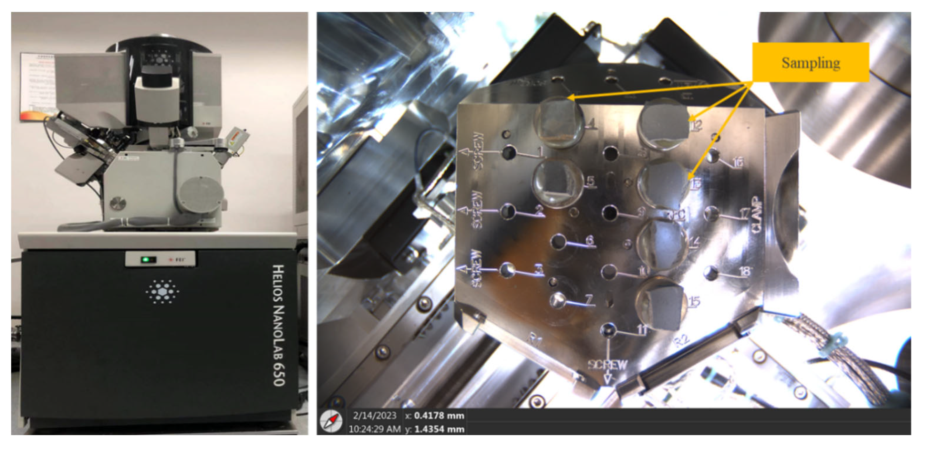
2.3.2. Argon-Ion Polishing Electron Microscope Experiment

Argon-ion polishing backscattered electron scan (FE-SEM) equipment was used to observe the changes in the set cements’ core pores and micro-cracks after thermal treatment (Figure 5). When preparing samples for argon-ion polishing, small samples of appropriate sizes were taken from the large samples. The small samples were cut and polished into smooth thin sheets using mechanical methods and then polished using an argon-ion polishing instrument. The argon gas was ionized into positively charged argon ions with a specific energy under the action of an electric field. Argon ions fly from the anode to the cathode and pass through the cathode hole to reach the sample’s surface, making the surface smooth and flat under the continuous bombardment of argon ions. The set cement treated with argon-ion polishing exhibited an extremely high flatness. The high-quality flat surface made the boundaries between mineral particles transparent, increasing the recognition of different mineral particle size ranges [34]. For the set cement before and after heat treatment, this method had a good observation effect on identifying organic matter and the internal nanopores and could display the chemical composition in the micro area.

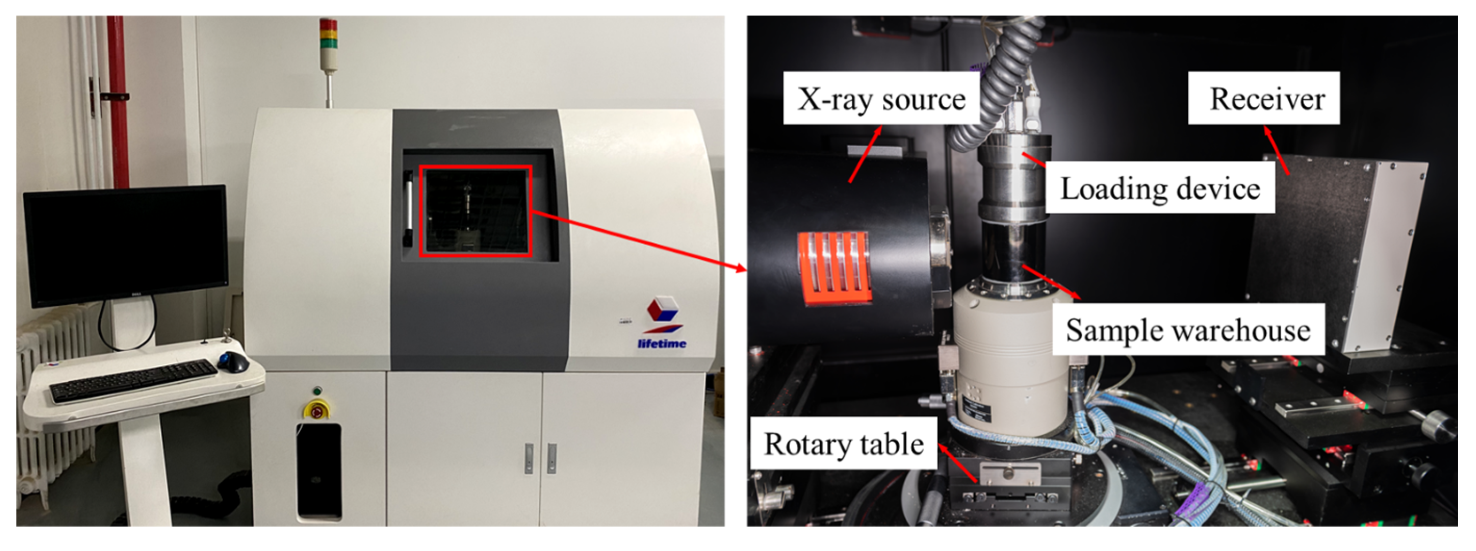
2.3.3. CT Scanning Experiment

As shown in Figure 6, the experiment was conducted using a CT real-time scanning device, which consists of four parts: a ray source, rotary table, detector, and loading device. During the experiment, a specimen was placed on the platform of the loading device, of which the maximum loading capacity was 5 kN, the adjustable displacement loading rate was 0.1–1 mm/min, and the applicable temperature range was 20 °C–150 °C. Afterward, the loading device was fixed on the rotating table of the scanning system for the CT scanning test, and a cone beam X-ray source was used for scanning, with a voltage of 120 kV and a current of 120 µA. X-rays pass through the specimen and record vertical projections on the detector. During a 360° rotation, specimen projections at different rotation angles were obtained at intervals of 0.4° [35]. After three-dimensional reconstruction, a three-dimensional image of the specimen with a voxel size of 16.58 µm × 16.58 µm × 16.58 µm was obtained, which was used to observe the internal damage characteristics of the sample under different thermal treatment conditions.

3. Results and Discussion

3.1. Study on the Mechanical Properties of Cement

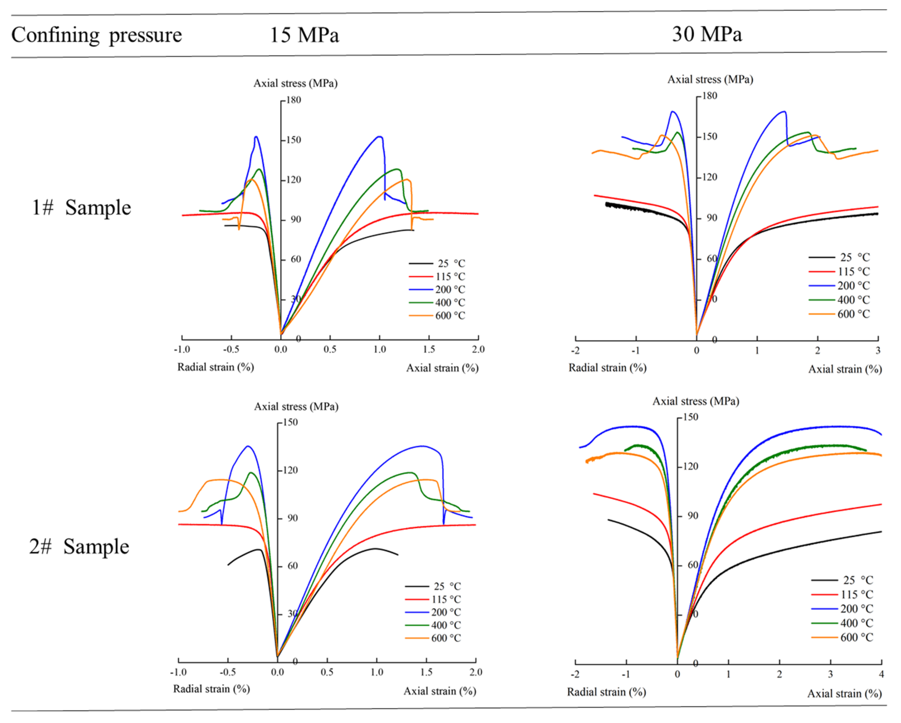
3.1.1. Stress–Strain Curve Analysis

During an underground building fire, the set cement is under the combined action of structural internal stress and crustal stress underground. Therefore, the set cement stress–strain analysis was carried out under different confining pressure conditions, as displayed in Figure 7. The following findings were made:
(1) Under confining pressure: The stress–strain curve in the early loading stage shows an approximately linear relationship, and the set cement has gone through the process of the crack being compressed, showing elastic deformation characteristics. When the stress reaches the yield strength of the set cement, the stress–strain curve shows the curve change, and as the pressure increases, the set cement shows the characteristics of plastic deformation.
(2) For the set cement with the same cement slurry formula: When the temperature increases from room temperature to 200 °C, the elastic deformation stage increases significantly, and the maximum deviatoric stress value of the set cement continues to grow. With the temperature rising from 200 °C to 600 °C, the elastic deformation stage begins to decrease, and the maximum deviatoric stress value continues to fall. With the higher confining pressure, the maximum deviatoric stress value of the set cement under the same temperature conditions is higher, and the plastic deformation stage of the set cement is more durable.
(3) For the set cement with different slurry formulas: The elastic stage of 1# set cement is longer, which shows a higher maximum deviatoric stress value. The short duration of the plastic deformation stage means that the set cement will break quickly once its yield strength is exceeded. Although the elastic phase of 2# set cement is shorter, it has a better plastic deformation ability after plastic deformation occurs, which means the set cement has better strain capacity under continuous stress.

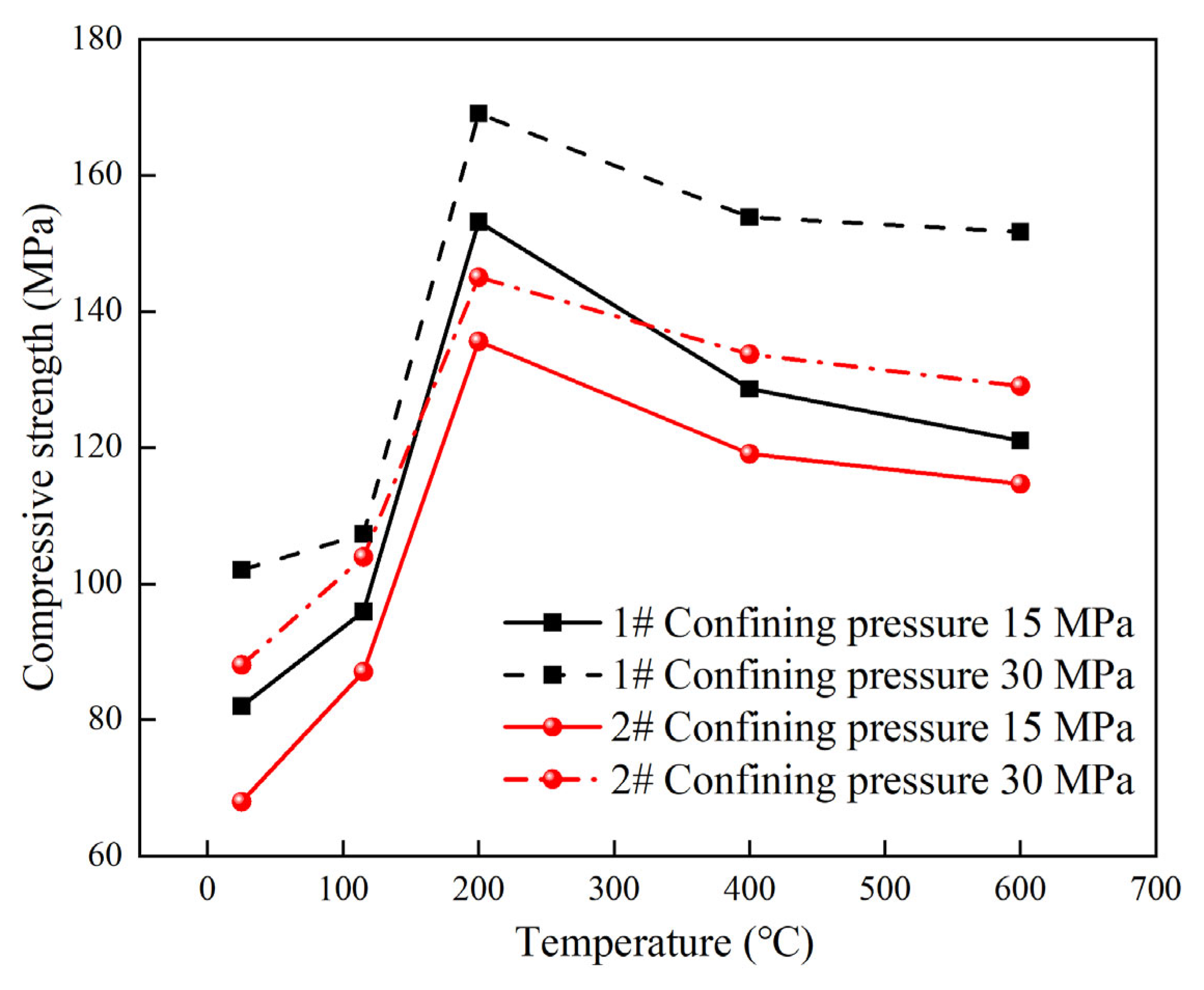
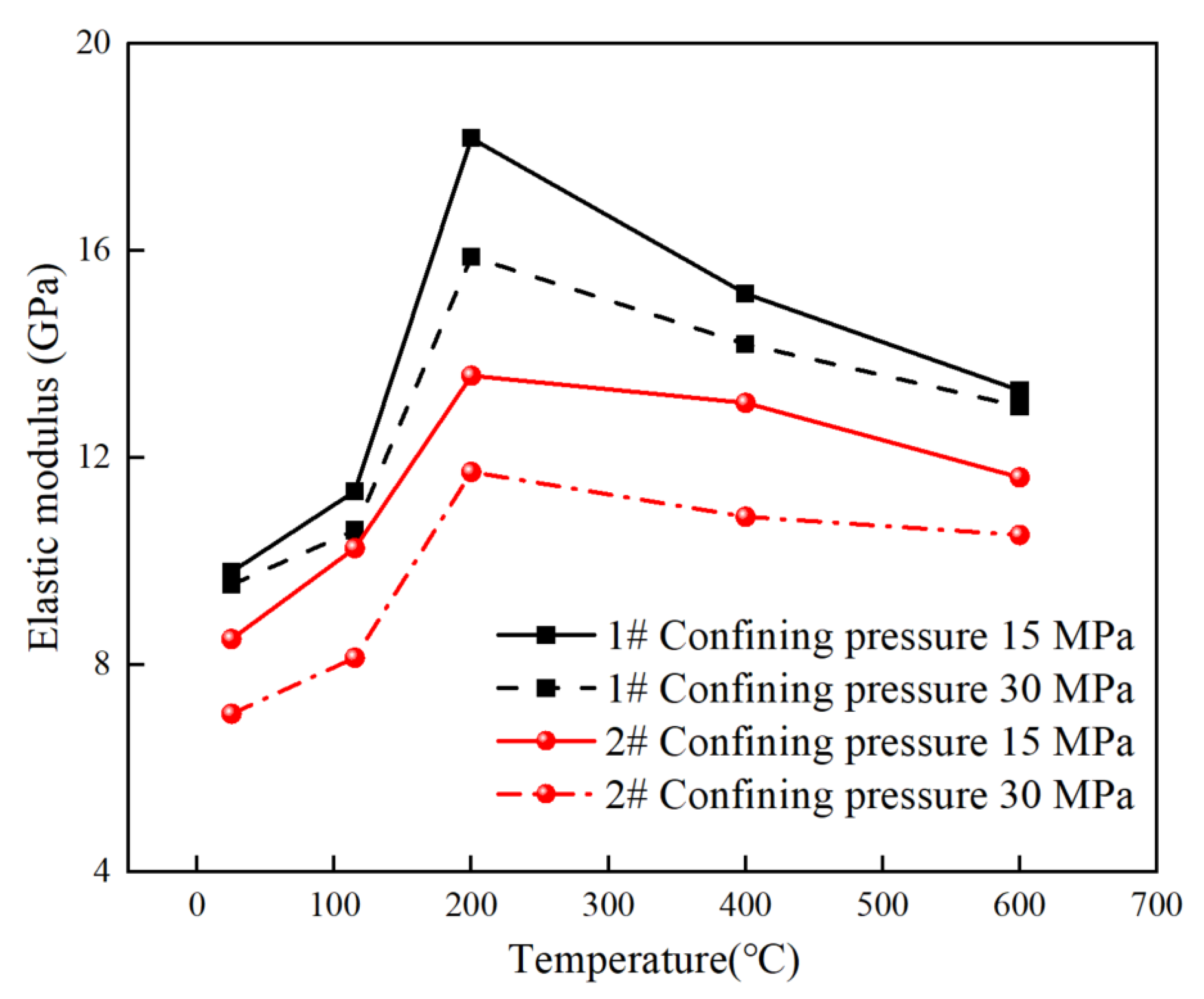
3.1.2. Variation of Mechanical Parameters

Following the stress–strain experimental results under the aforementioned confining pressure conditions, the compressive strength of the set cement at different temperatures was obtained, as displayed in Figure 8. For these two types of set cement, the compressive strengths exhibited similar variation patterns: As the heating temperature continues to rise, the compressive strength of the set cement first increases (25 °C–200 °C) and then decreases (200 °C–600 °C); the strength of the set cement reaches its peak after thermal treatment at 200 °C. Under the same thermal treatment condition, the higher the confining pressure, the greater the compressive strength of the set cement.
With 1# set cement as an example, when the confining pressure is 30 MPa under normal temperature conditions, the compressive strength of set cement is 102.03 MPa. As the temperature continues to increase (200 °C), the compressive strength of set cement reaches 169.08 MPa, with an elevation of 65.7%. The set cement matrix expands under the increased temperature, causing the internal pore volume to shrink continuously. Since the strength of the set cement reaches full development under this temperature condition, the compressive strength of the set cement specimen reaches its highest level.
As the subsequent thermal treatment temperature continues to increase (400 °C–600 °C), the compressive strength of the rock reduces to 153.85 MPa (400 °C) and 151.67 MPa (600 MPa). This is because higher temperatures cause the number of pores in set cement to increase. In addition, some pores aggregate and penetrate to form micro-cracks. As this develops, complex cracks appear, causing the compressive strength of set cement to decrease.
The 2# set cement had similar change patterns. When the confining pressure is 30 MPa, under normal temperature conditions (25 °C) and the thermal treatment temperatures of 115 °C, 200 °C, 400 °C, and 600 °C, the compressive strength is 88.06 MPa, 103.93 MPa, 145.03 MPa, 133.73 MPa, and 129.05 MPa, respectively.
In order to further verify this conclusion, a low-field nuclear magnetic resonance experiment was carried out to analyze the changes in pores under different temperature conditions and the penetration between different types of pores.
According to the stress–strain curve of the set cement at different temperatures obtained above, the elastic modulus under different thermal treatment conditions was calculated, as shown in Figure 9. Both types of set cement have similar change characteristics: the elastic modulus first increases and then decreases as the temperature increases, which is identical to the change pattern of compressive strength. The elastic modulus will decrease with the same thermal treatment temperature as the confining pressure increases.
With the confining pressure being 30 MPa, the elastic moduli of 1# set cement and 2# set cement at room temperature are 9.55 GPa and 7.07 GPa, respectively. When the temperature of the thermal treatment increases to 115 °C, 200 °C, 400 °C, and 600 °C, the elastic moduli of 1# set cement are 10.60 GPa, 15.89 GPa, 14.20 GPa, and 12.96 GPa, and the elastic moduli of 2# set cement are 8.14 GPa, 11.73 GPa, 10.86 GPa, and 10.51 GPa.
It is worth mentioning that when the set cement is in the same mechanical environment underground, a higher elastic modulus may cause the cement sheath to bear more significant stress, making it more susceptible to damage under pressure or tension and the risk of integrity failure. Therefore, it can be concluded that 1# set cement has a higher compressive strength and elastic modulus, and can withstand greater external stress under the same mechanical environment.

3.2. Changes in Pore and Permeability Characteristics under Thermal Treatment

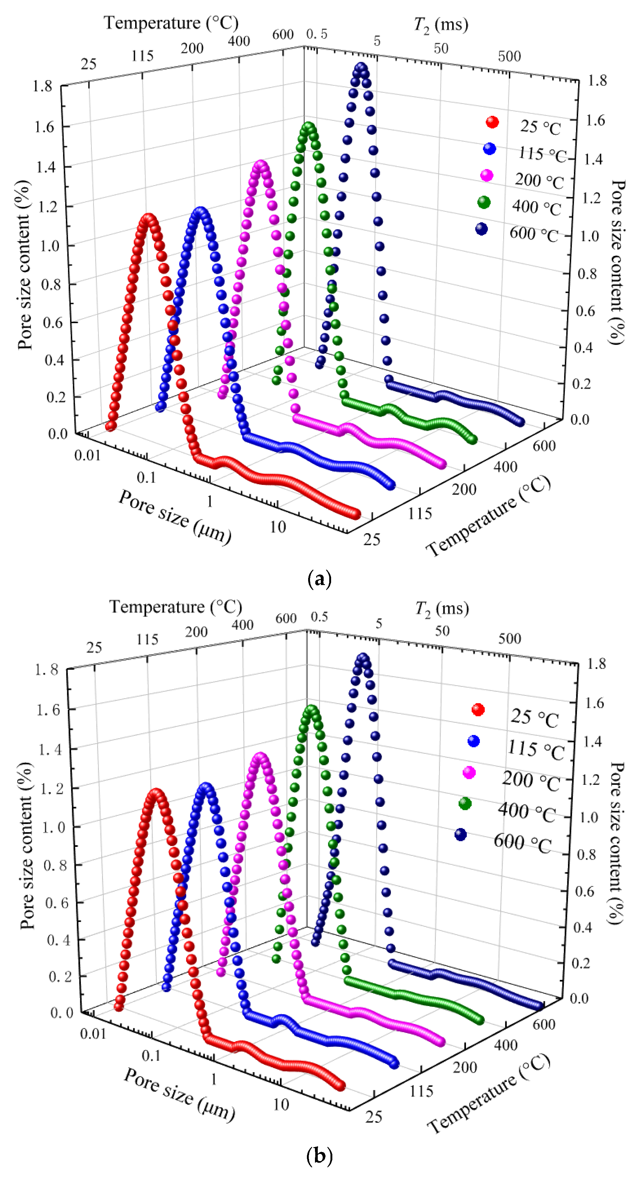
3.2.1. Aperture Distribution Analysis

During an underground building fire, the mechanical properties of set cement continue to deteriorate in the higher-temperature environment [36,37]. It is because the continuous increase in pores leads to a constant decrease in the bearing capacity of set cement. Meanwhile, pore changes will also affect the set cement’s permeability and sealing ability. Considering that nuclear magnetic resonance technology is a crucial way to carry out non-destructive measurements of pore permeability characteristics, the changes in set cement pores under different thermal treatment conditions are measured using NMR devices.
Figure 10a characterizes the pore size distribution of a 1# set cement specimen at room temperature and different thermal treatment temperatures. The following can be seen:
(1) Change in peak value: Before the thermal treatment, the highest peak value is 1.17%, and the pore size is 0.52 μm. When the temperature is elevated to 115 °C, the peak value decreases slightly (1.14%), and the pore size is 0.49 μm. As the temperature continues to increase to 200 °C, 400 °C, and 600 °C, the peak values increase to 1.33% (pore size is 0.078 μm), 1.48% (pore size is 0.084 μm), and 1.76% (pore size is 0.12 μm). This indicates that as the temperature increases, the peak value decreases and then increases. In addition, the pore size corresponding to the peak point continues to grow.
According to the division intervals of the small pore (≤0.1 μm), mesopore (0.1 μm < diameter ≤ 1 μm), and macropore (>1 μm), the pores of the set cement under normal temperature conditions are mainly small. With the temperature increasing to 600 °C, the pores of the set cement are mainly mesopores. There are some macropores in the set cement, but the proportion is small (less than 0.2%).
(2) Change law of pores with maximum size: Before the thermal treatment, the maximum pore size is 0.30 μm. When the temperature is 115 °C, 200 °C, 400 °C, and 600 °C, the maximum pore size is 0.27 μm, 0.29 μm, 0.36 μm, and 0.41 μm, respectively. It can be seen that the change pattern of the maximum pore size is first decreasing and then increasing.
The set cement formed by the 2# slurry has a similar change pattern. When the temperatures are room temperature (25 °C), 115 °C, 200 °C, 400 °C, and 600 °C, the peak values are 2.77% (pore size is 0.060 μm), 2.58% (pore size is 0.055 μm), 3.41% (pore size is 0.073 μm), and 4.20% (pore size is 0.12 μm). Correspondingly, the maximum pore diameters are 0.34 μm, 0.24 μm, 0.38 μm, 0.40 μm, and 0.44 μm, respectively.

3.2.2. Analysis of Pore Development

Based on the measurement of the pore size distribution using the NMR device, the change pattern of the porosity of the set cement specimen at different temperatures was analyzed, as shown in Figure 11. The following can be seen:
(1) At room temperature, the porosities of the 1# and 2# set cements are 32.48% and 35.29%, respectively. When the temperature increases to 115 °C, the porosities of the 1# and 2# set cement decrease to 31.59% and 34.84%, with a decrease rate of 2.74% and 1.27%. This is mainly because the set cement has many native pores as an artificial specimen. As the temperature continues to increase, the internal matrix and particles of the set cement undergo thermal expansion, causing the native pores to be compressed, and the number and size of pores to decrease continuously.
(2) As the temperature continues to increase (200 °C, 400 °C, 600 °C), the porosities of the 1# set cement and 2# set cement show increasing trends. Specifically, the porosity of 1# set cement is 33.57%, 34.10%, and 39.04%; the porosity of 2# set cement is 35.35%, 36.24%, and 40.45%. This is mainly because as the temperature increases, the original pores continue to grow, some small pores transform into medium to large pores, and new small pores are generated, leading to a continuous increase in porosity.
The change in porosity will lead to corresponding changes in permeability and further affect the sealing performance of the set cement. The permeability of set cement was measured as shown in Figure 12. Thus, the permeability changes of the set cement can be classified into two stages:
(1) Stage with slow growth in permeability: Under room temperature conditions, the permeabilities of the 1# and 2# set cement are 0.67 mD and 1.31 mD, respectively. This indicates that 1# set cement has better sealing performance. When the temperature is 115 °C, 200 °C, and 400 °C, the permeability increases slowly, and the permeability of 1# set cement is 1.39 mD, 1.40 mD, and 1.88 mD, and that of 2# set cement is 1.76 mD, 1.89 mD, and 2.05 mD. This is mainly because at this stage, although some small pores merged into medium or large pores and some new small pores were generated, the vast majority of pores did not connect with each other, resulting in a limited increase in permeability despite some rise.
(2) Stage with rapid growth in permeability: When the temperature reaches 600 °C, the permeabilities reach 4.61 mD and 5.43 mD, which shows rapid increases compared with those at 400 °C. This is mainly because under this temperature condition, with the continuous increases in large, medium, and small pores, there is connectivity between the different levels of pores, leading to significant increases in permeability.

3.2.3. Relationship between Porosity and Permeability

Based on the analysis above on porosity and permeability under different temperature conditions, the corresponding relationship between porosity and permeability was established, as shown in Figure 13. When the temperature increases from room temperature (25 °C) to 115 °C, a negative correlation exists between porosity and permeability. As the temperature rises (200 °C, 400 °C, and 600 °C), a positive relationship exists between porosity and permeability. From the perspective of a growth trend, the porosity of 2# set cement has a higher growth rate.

3.3. Visualization Analysis of Sewage Sludge under High- and Ultra-High-Temperature Conditions

3.3.1. FE-SEM Imaging Analysis

In order to further analyze the changes in the micromorphology of the set cement during thermal treatment, the same specimen was selected to be heated at temperatures of 115 °C, 200 °C, 400 °C, and 600 °C. The FE-SEM method was applied to observe the same position at different temperatures, as presented in Figure 14. The following findings were made:
(1) The set cement matrix is relatively dense under normal temperature conditions, without apparent micro-cracks.
(2) When the heating temperature is 115 °C, the pore and micro-crack changes are minor, indicating that thermal stress has a negligible impact on the set cement. The original micro-cracks become more apparent as the temperature increases to 200 °C. With the thermal treatment temperature reaching 400 °C, the cracks on the set cement matrix become increasingly prominent. As more cracks develop along the edge of the crystal, some new cracks appear. This is mainly because different types of crystals have different thermal expansion coefficients, so cracks first appear along the edge of the crystal during the heating process. At the same time, as the temperature continues to rise (600 °C), the original cracks continue to expand, resulting in a significant increase in the widths and lengths of the micro-cracks, and different cracks gradually begin to merge, making the morphology of micro-cracks more complex.

3.3.2. CT Scanning Analysis

To further characterize the occurrence and development of the set cement pores under different thermal treatment temperature conditions, CT scanning experiments were performed on the set cement to varying temperatures before and after heating, as shown in Figure 15. The following findings were made:
(1) For 10 set cement samples under the original temperature conditions, it can be seen that these samples are filled with many small pores, which is consistent with the measurement data in that the original pores are mainly small pores. At the same time, some samples showed significant porosity during the sample preparation process.
(2) When the thermal treatment temperature is 115 °C, comparing specimens before and after heating shows little difference. With the thermal treatment temperature increasing to 200 °C, the small pores in the samples increase significantly. When the temperature rises to 400 °C, small pores increase significantly. Some small pores have aggregated into mesopores and macropores. When the thermal treatment temperature rises to 600 °C, mesopores and fine pores gradually increase, and the pores have covered the entire specimen.
(3) After comparing the two types of specimens, the generation of pores in 2# set cement is more sensitive to temperature.

4. Conclusions

Two high-temperature-resistant cement slurry systems were designed and configured based on an ultra-high-temperature environment. Mechanical, porosity, and permeability experiments were conducted on the set cement under high- and ultra-high-temperature conditions, and the experimental results were analyzed. The conclusions are as follows:
  • Two types of high-temperature-resistant cement slurries were designed, and uniaxial compression tests were conducted after high-temperature and high-pressure curing. The results indicate that as the heating temperature continues to rise, the compressive strength of the set cement first increases (25 °C–200 °C) and then decreases (200 °C–600 °C), and the strength of the set cement reaches its peak after thermal treatment at 200 °C.
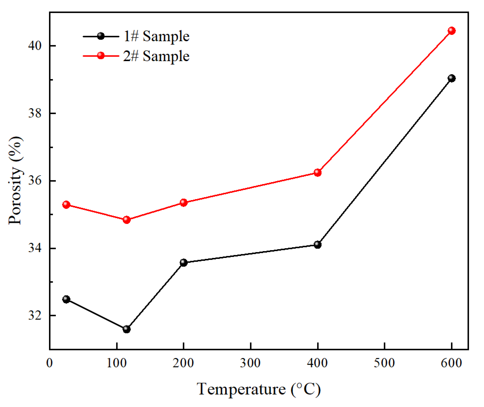
  • The porosity and permeability characteristics of set cement after thermal treatment were measured using a low-field NMR experimental device. The results show that with the continuous increase in temperature, the porosity of cement paste first decreases (25 °C–115 °C) and then increases (115 °C–600 °C). The penetration first slowly increases (25 °C–400 °C) and then rapidly increases (400 °C–600 °C).
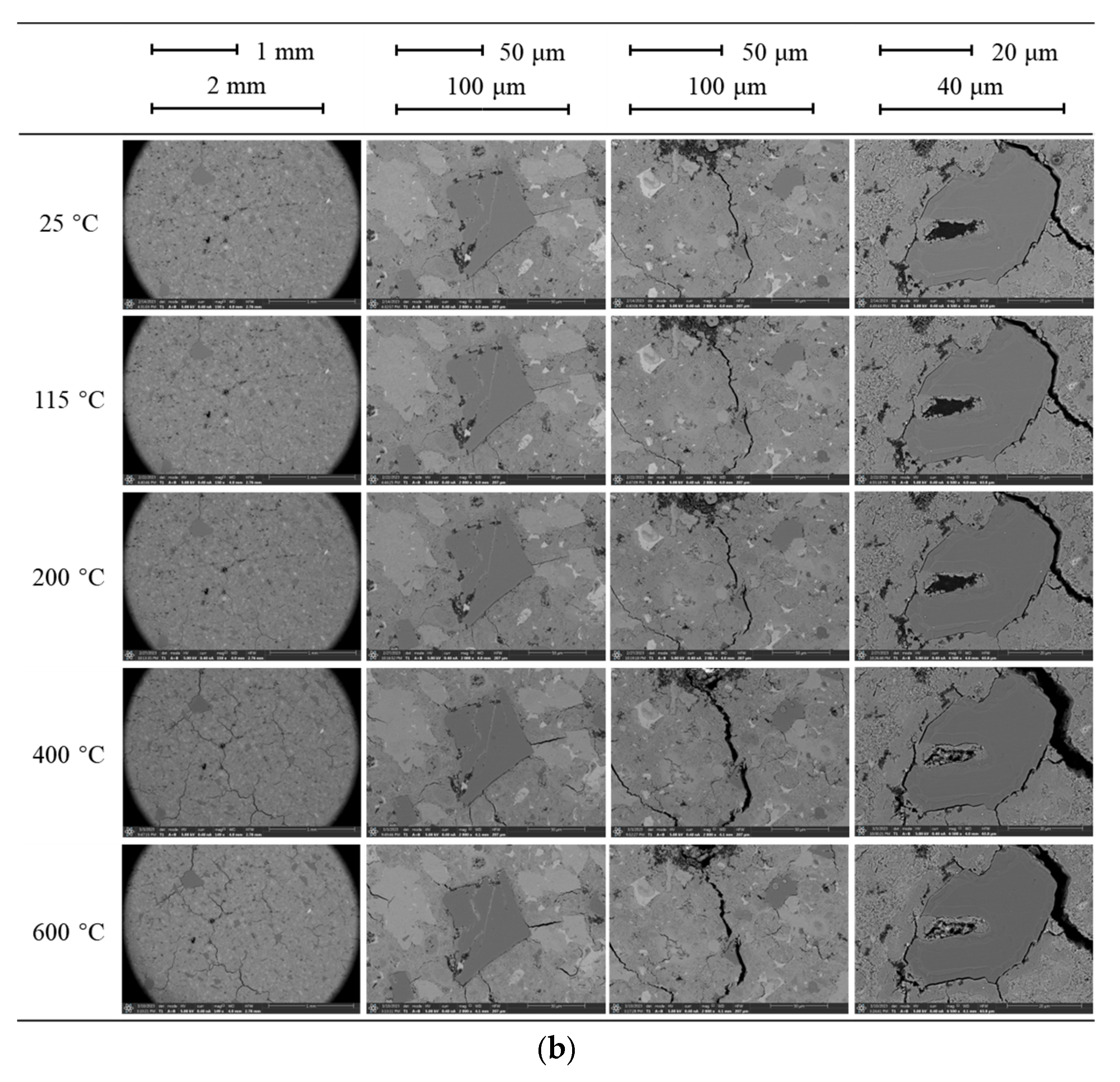
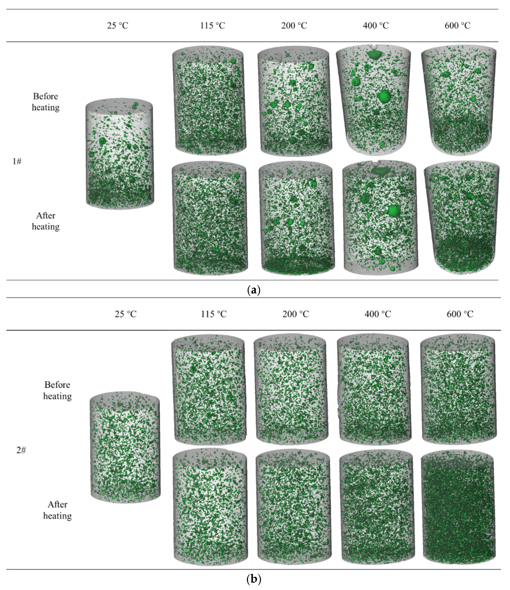
  • Visualization experiments were conducted on the micro-cracks and pore distribution of set cement based on FE-SEM and CT scanning. The experimental results show that when the thermal treatment temperature is 200 °C–600 °C, the number of pores on the cement matrix after a thermal roughening treatment has significantly increased, and some pores have polymerized and formed micro-cracks.

Author Contributions

Y.X.: Methodology, Writing, Original draft. J.X.: Validation, Formal analysis. J.F.: Validation. C.M.: Validation, Formal analysis. X.Y.: Visualization. Y.T.: Formal analysis. X.L.: Writing, Visualization. All authors have read and agreed to the published version of the manuscript.

Funding

This research was funded by National Natural Science Foundation of China (52374001).

Data Availability Statement

The datasets in the current study are available from the corresponding author upon reasonable request.

Conflicts of Interest

Author Jiajia Feng was employed by the company CNPC Xibu Drilling Engineering Company Limited. Authors Xiutian Yang, Yudong Tian and Xin Liu were employed by the company Daqing Drilling and Exploration Engineering Company. The remaining authors declare that the research was conducted in the absence of any commercial or financial relationships that could be construed as a potential conflict of interest.

References

  1. Zhao, Y.S.; Liang, W.G.; Feng, Z.J. Introduction to In-Situ Modification Mining by Fluidization; Science Press: Beijing, China, 2019; pp. 291–335. [Google Scholar]
  2. Feng, Z.J.; Zhao, Y.S.; Zhou, A.C.; Zhang, N. Development program of hot dry rock geothermal resource in the Yangbajing Basin of China. Renew. Energy 2012, 39, 490–495. [Google Scholar] [CrossRef]
  3. Yin, W.T.; Zhao, Y.S.; Feng, Z.J. Experimental research on the rupture characteristics of fractures subsequently filled by magma and hydrothermal fluid in hot dry rock. Renew. Energy 2019, 139, 71–79. [Google Scholar] [CrossRef]
  4. Zhao, Y.S.; Feng, Z.J.; Zhao, Y.; Wan, Z.J. Experimental investigation on thermal cracking, permeability under HTHP and application for geothermal mining of HDR. Energy 2017, 132, 305–314. [Google Scholar] [CrossRef]
  5. Martin, C.D.; Christiansson, R. Estimating the potential for spalling around a deep nuclear waste repository in crystalline rock. Int. J. Rock Mech. Min. Sci. 2009, 46, 219–228. [Google Scholar] [CrossRef]
  6. Bhutto, A.W.; Bazmi, A.A.; Zahedi, G. Underground coal gasification: From fundamentals to applications. Prog. Energy Combust. Sci. 2013, 39, 189–214. [Google Scholar] [CrossRef]
  7. Šolcová, O.; Soukup, K.; Rogut, J.; Stanczyk, K.; Schneider, P. Gas transport through porous strata from underground reaction source; The influence of the gas kind, temperature and transport-pore size. Fuel Process. Technol. 2009, 90, 1495–1501. [Google Scholar] [CrossRef]
  8. Wan, Z.J.; Feng, Z.J. The Coupled Thermo-Mechanical Characteristics of Coal and Their Application; Science Press: Beijing, China, 2014; pp. 130–145. [Google Scholar]
  9. Curiel-Esparza, J.; Canto-Perello, J.; Calvo, M.A. Establishing sustainable strategies in urban underground engineering. Sci. Eng. Ethics 2004, 10, 523–530. [Google Scholar] [CrossRef]
  10. CAE. The Blue Book of Urban Underground Space Development in China in 2021; Strategic Consulting Center of Chinese Academy of Engineering: Beijing, China, 2021. [Google Scholar]
  11. Yuan, Q.; Zhu, H.; Zhang, X.; Zhang, B.; Zhang, X. An Integrated Quantitative Risk Assessment Method for Underground Engineering Fires. Int. J. Environ. Res. Public Health 2022, 19, 16934. [Google Scholar] [CrossRef]
  12. She, L.; Chen, Z.; Zheng, Z.G. Urban Underground Space Risk Early Warning Management; Science Press: Beijing, China, 2014. [Google Scholar]
  13. Chen, Q.; Zhu, H.H.; Yan, Z.G.; Ju, J.W.; Jiang, Z.W.; Wang, Y.Q. A multiphase micromechanical model for hybrid fiber reinforced concrete considering the aggregate and ITZ effects. Constr. Build. Mater. 2016, 114, 839–850. [Google Scholar] [CrossRef]
  14. Ju, J.; Wu, Y. Stochastic micromechanical damage modeling of progressive fiber breakage for longitudinal fiber-reinforced composites. Int. J. Damage Mech. 2015, 25, 203–227. [Google Scholar] [CrossRef]
  15. Kale, S.; Ostoja-Starzewski, M. Representing stochastic damage evolution in disordered media as a jump Markov process using the fiber bundle model. Int. J. Damage Mech. 2016, 26, 147–161. [Google Scholar] [CrossRef]
  16. Park, S.M.; Yang, B.J.; Kim, B.R.; Ha, S.K.; Lee, H.K. Structural strengthening and damage behaviors of hybrid sprayed fiber-reinforced polymer composites containing carbon fiber cores. Int. J. Damage Mech. 2016, 26, 358–376. [Google Scholar] [CrossRef]
  17. Wu, Y.; Ju, J.W. Elastoplastic damage micromechanics for continuous fiber-reinforced ductile matrix composites with progressive fiber breakage. Int. J. Damage Mech. 2016, 26, 4–28. [Google Scholar] [CrossRef]
  18. Yan, Z.G.; Zhang, Y.; Ju, J.W.; Chen, Q.; Zhu, H.H. An equivalent elastoplastic damage model based on micromechanics for hybrid fiber-reinforced composites under uniaxial tension. Int. J. Damage Mech. 2017, 28, 79–117. [Google Scholar] [CrossRef]
  19. Ma, Q.M.; Guo, R.X.; Zhao, Z.M.; Lin, Z.W.; He, K.C. Mechanical properties of concrete at high temperature—A review. Constr. Build. Mater. 2015, 93, 371–383. [Google Scholar] [CrossRef]
  20. Xiao, J.Z.; König, G. Study on concrete at high temperature in China—An overview. Fire Saf. J. 2004, 39, 89–103. [Google Scholar] [CrossRef]
  21. Xiao, J.Z.; Xie, Q.H.; Xie, W.G. Study on high-performance concrete at high temperatures in China (2004–2016)—An updated overview. Fire Safety J. 2018, 95, 11–24. [Google Scholar] [CrossRef]
  22. Phan, L.T.; Carino, N.J. Review of mechanical properties of HSC at elevated temperature. J. Mater. Civil Eng. 1998, 10, 58–65. [Google Scholar] [CrossRef]
  23. Lin, Y.H.; Deng, K.H.; Yi, H.; Zeng, D.Z.; Tang, L.; Wei, Q. Integrity tests of cement sheath for shale gas wells under strong alternating thermal loads. Nat. Gas Ind. B 2020, 7, 671–679. [Google Scholar] [CrossRef]
  24. Zhang, G.Y.; Wu, Z.Q.; Cheng, X.W.; Sun, X.L.; Zhang, C.M.; Zhou, M. Mechanical properties of high-ferrite oil-well cement used in shale gas horizontal wells under various loads. Constr. Build. Mater. 2022, 319, 126067. [Google Scholar] [CrossRef]
  25. Li, H.L.; Pang, X.Y.; Zhang, J.; Shi, X. Mechanical properties of low-density cement under shale oil in-situ conversion conditions. Constr. Build. Mater. 2023, 393, 131970. [Google Scholar] [CrossRef]
  26. Zhang, Y.H.; Xu, M.B.; Song, J.J.; Wang, C.L.; Wang, X.L.; Hamad, B.A. Study on the corrosion change law and prediction model of set cement in oil wells with CO2 corrosion in ultra-high-temperature acid gas wells. Constr. Build. Mater. 2022, 323, 125879. [Google Scholar] [CrossRef]
  27. Hao, H.Y.; Song, J.W.; Chen, M.Z.; Yan, X.; Zhang, K.F. Rheological and mechanical properties of oil-well cement reinforced by hybrid inorganic fibers. Constr. Build. Mater. 2023, 377, 131002. [Google Scholar] [CrossRef]
  28. Bathija, A.P.; Boyd, P.; Martinez, R. Cement sheath integrity at simulated reservoir conditions of pressure, temperature, and wellbore configuration in a laboratory setup. Geoenergy Sci. Eng. 2023, 232, 212446. [Google Scholar] [CrossRef]
  29. Sun, L.J.; Pang, X.Y.; Liu, H.J.; Wang, C.C.; Yu, J.W.; Zhao, P.Y. Experimental study of pure Class G cement hydration up to 150 °C and 50 MPa. J. Mater. Res. Technol. 2023, 25, 1463–1482. [Google Scholar] [CrossRef]
  30. Weibel, R.; Olivarius, M.; Jakobsen, F.C.; Whitehouse, M.; Larsen, M.; Midtgaard, H.; Nielsen, K. Thermogenetic degradation of early zeolite cement: An important process for generating anomalously high porosity and permeability in deeply buried sandstone reservoirs? Mar. Petrol. Geol. 2019, 103, 620–645. [Google Scholar] [CrossRef]
  31. Bai, S.; Yu, L.B.; Guan, X.C.; Li, H.; Ou, J.P. Study on the long-term chloride permeability of nano-silica modified cement pastes cured at negative temperature. J. Build. Eng. 2022, 57, 104854. [Google Scholar] [CrossRef]
  32. Yin, T.B.; Li, Q.; Li, X.B. Experimental investigation on mode I fracture characteristics of granite after cyclic heating and cooling treatments. Eng. Fract. Mech. 2019, 222, 106740. [Google Scholar] [CrossRef]
  33. Li, Q.; Li, X.B.; Yin, T.B. Factors affecting pore structure of granite under cyclic heating and cooling: A nuclear magnetic resonance investigation. Geothermics 2021, 96, 102198. [Google Scholar] [CrossRef]
  34. Xi, Y.; Xing, J.H.; Jiang, H.L.; Fan, L.F.; Li, J. Pore characteristic evolution and damage deterioration of granite subjected to the thermal and cooling treatments combined with the NMR method. Bull. Eng. Geol. Environ. 2023, 85, 182. [Google Scholar] [CrossRef]
  35. Fan, L.F.; Gao, J.W.; Du, X.L.; Wu, Z.J. Spatial gradient distributions of thermal shock-induced damage to granite. J. Rock Mech. Geotech. 2020, 12, 917–926. [Google Scholar] [CrossRef]
  36. Qiao, Y.F.; Xiao, Y.M.; Ding, W.Q.; He, M.C. Effect of rock nonlinear mechanical behavior on plastic zone around deeply buried tunnel: A numerical investigation. Comput. Geotech. 2023, 161, 105532. [Google Scholar] [CrossRef]
  37. Xu, Y.Y.; Tang, T.T.; Liu, M.; Huang, J.Q. Experimental investigation of post-fire seismic behavior of reinforced high-strength concrete shear walls. Eng. Struct. 2023, 297, 117010. [Google Scholar] [CrossRef]
Figure 1. Experimental specimen and geometric dimensions.
Buildings 14 00303 g001
Figure 2. Thermal and cooling processes.
Buildings 14 00303 g002
Figure 3. Experimental procedure.
Buildings 14 00303 g003
Figure 4. Vacuum saturation and NMR instruments.
Buildings 14 00303 g004
Figure 5. Argon-ion polishing electron microscope equipment and core sampling.
Buildings 14 00303 g005
Figure 6. CT scanning device.
Buildings 14 00303 g006
Figure 7. Stress–strain curves of slurry at different temperatures.
Buildings 14 00303 g007
Figure 8. Compressive strength of set cement under different temperatures and confining pressure conditions.
Buildings 14 00303 g008
Figure 9. Elastic modulus of set cement under different temperatures and confining pressure conditions.
Buildings 14 00303 g009
Figure 10. Change patterns of set cement pores under different temperature conditions. (a) Pore size distribution of 1# sample. (b) Pore size distribution of 2# sample.
Buildings 14 00303 g010
Figure 11. Porosity changes under different temperature conditions.
Buildings 14 00303 g011
Figure 12. Permeability changes under different temperature conditions.
Buildings 14 00303 g012
Figure 13. Corresponding relationship between porosity and permeability.
Buildings 14 00303 g013
Figure 14. Development regularity of micro-cracks in sewage mud and stone at different temperatures. (a) 1#- SEM image. (b) 2#- SEM image.
Buildings 14 00303 g014aBuildings 14 00303 g014b
Figure 15. Development of set cement pores under different temperature conditions. (a) 1# Sample. (b) 2# Sample.
Buildings 14 00303 g015
Disclaimer/Publisher’s Note: The statements, opinions and data contained in all publications are solely those of the individual author(s) and contributor(s) and not of MDPI and/or the editor(s). MDPI and/or the editor(s) disclaim responsibility for any injury to people or property resulting from any ideas, methods, instructions or products referred to in the content.

