Article

Study on the Influence and Optimization Design of Viscous Damper Parameters on the Damping Efficiency of Frame Shear Wall Structure

1
College of Architecture and Civil Engineering, Kunming University, Kunming 650214, China
2
Institute of Engineering Earthquake Resistance and Disaster Reduction, Kunming University, Kunming 650214, China
3
College of Architecture and Civil Engineering, Dianchi College of Yunnan University, Kunming 650228, China
4
College of Urban Construction, Yunnan Open University & Yunnan Vocational and Technical College of National Defense Industry, Kunming 650032, China
*
Author to whom correspondence should be addressed.
Buildings 2024, 14(2), 497; https://doi.org/10.3390/buildings14020497
Submission received: 15 January 2024 / Revised: 4 February 2024 / Accepted: 7 February 2024 / Published: 10 February 2024
(This article belongs to the Special Issue Advances and Applications in Structural Vibration Control)

Abstract

:
This study investigates the influence of viscous damper parameters on the damping efficiency of frame shear wall structures. Taking a specific frame shear wall structure as the background, a three-dimensional finite element model is established using a nonlinear dynamic time–history analysis method. The damping ratio, reduction in vertex displacement, reduction in base shear, and inter-story drift utilization rate are selected as the damping performance indicators. Firstly, a sensitivity analysis is conducted to study the influence of different viscous damper parameters on these indicators. Then, the relationship models between the viscous damper parameters and the indicators are fitted using the response surface method, and the fitting effect is evaluated through an F-test and determination coefficient R2. Finally, an objective function based on key damping performance indicators is established to solve for the optimal parameters. The results show that the traditional sensitivity analysis method is unable to comprehensively consider the combined effects of different damping efficiency indicators. The response surface method has high fitting accuracy and good predictability and can serve as an optimization model. Considering the stiffness of supporting components matched with the viscous damper parameters, the feasibility of the optimal damping parameters is demonstrated from an engineering application perspective. A simple and easy-to-operate damping design flowchart is proposed, providing important guidance and reference for designers in frame shear wall structure damping design in the future.

1. Introduction

On 1 September 2021, with the implementation of the “Regulations on Seismic Management of Construction Engineering” in China, the application of energy dissipation and isolation technology has sparked a new wave nationwide. Energy dissipation structures [1,2] refer to the installation of energy dissipation devices in building structures to dissipate a portion of the seismic energy input, thereby reducing the response of the upper structure under seismic excitation and mitigating or even avoiding damage to the main structure. The control types of energy dissipation systems mainly include active control, semi-active control, passive control, and intelligent control [3,4,5]. The common passive energy dissipation devices include velocity-dependent dampers, displacement-dependent dampers, and hybrid dampers. Viscous dampers [6] are the most common velocity-based dissipative devices used to reduce the vibration response of structures by utilizing the damping characteristics of viscous materials. When a structure is subjected to external forces, the viscous material inside the damper generates damping forces, allowing the structure to absorb and dissipate energy. Viscous dampers have several advantages compared to other types of dampers. Firstly, they can provide higher additional damping ratios, effectively reducing the vibration amplitude and response of the structure. Secondly, they exhibit stable and reliable damping characteristics within the frequency response range. Lastly, viscous dampers have a relatively simple construction, resulting in lower installation and maintenance costs. As a result, they have been widely applied in engineering practice.
Lin et al. [7] conducted a comprehensive study on the earthquake response of elastic single-degree-of-freedom systems with attached nonlinear viscous dampers. And Gherbi et al. [8] researched the simplified design strategy of nonlinear fluid viscous dampers for MDOF structures. A computational framework is proposed for the design of earthquake-resistant buildings using genetic algorithms to optimize robust designs with passive dampers [9]. Rayegani et al. [10] conducted a study on retrofitting a steel moment frame structure with four-joint rotational friction dampers to improve seismic behavior during mainshock–aftershock sequences. Ding et al. [11] presented a seismic performance analysis of viscous damping outrigger technology for super high-rise buildings, demonstrating its effectiveness in enhancing structural security and reducing construction costs. The application of viscous dampers in adjacent buildings is also widespread. Scholars have conducted in-depth research on the dynamic response [12,13,14,15] and seismic performance [16,17] of structures under seismic excitation. It can be observed from the literature mentioned above that passive energy dissipation devices, particularly viscous dampers, are widely utilized in various structural systems. However, their application in reinforced concrete frame shear walls is almost nonexistent.
Numerous scholars have conducted comprehensive research on the calculation methodology for additional damping ratio and the effective evaluation of the added dampers. Xu et al. [18] proposed a method for calculating the additional damping ratio considering the influence of excitation frequency. Diotallevi et al. [19] conducted a simplified method for assessing the supplemental damping ratio using a new dimensionless parameter. This was verified through numerical investigations on single- and multi-degree of freedom systems under harmonic excitations and ground motions. Hwang et al. [20] investigated how to incorporate the consideration of additional damping ratio in the practical engineering application of the normative design methods (FEMA273 or FEMA356) and related research report methods. Rama et al. [21], Xie et al. [22], and Occhiuzzi [23] conducted a comprehensive study on the enhancement of structural seismic performance and effectiveness assessment of dampers installed in buildings. However, there has been no specific research on the influence of viscous damper parameters on the additional damping ratio and the effectiveness of the damper.
The purpose of attaching viscous dampers is to reduce the structural response during an earthquake. Different scholars have conducted detailed research on optimal seismic response control and optimal damper placement. Singh et al. [24] and Aguirre et al. [25] investigated the optimal seismic response of structures with additional viscous dampers. The optimal placement of dampers has been investigated in terms of the simplified methods of multi-degree-of-freedom systems [26], transfer functions [27], critical excitation [28], and distribution of damping coefficients [29]. Pollini et al. [30] conducted research on minimum-cost optimization of viscous dampers and their supporting members for seismic retrofitting. The optimal design of frame structures [31], steel frame structures [32], and seismic retrofit structures [33] with added viscous dampers has also been studied. Seismic response is essentially a random vibration, which needs to be understood from a probabilistic perspective. The researchers have also studied the random vibration response of structures with additional viscous dampers under seismic excitation [34], as well as the research on their optimized design [35,36], and conducted probabilistic seismic response assessment studies [37,38]. However, they did not consider the influence of different damper parameters on the optimal seismic response control and optimal damper placement.
In summary, there is still limited research detailing the influence of viscous dampers’ parameters on the seismic performance of damping structures, especially in the application research of frame shear wall structures. Therefore, this paper aims to investigate the influence of damper parameters in detail on the seismic efficiency of frame shear wall structures with attached viscous dampers through various damping indicators. The study proposes to use a response surface-based method, which has been applied in bridge structures [39,40]. In previous conventional structural design optimization methods, optimization was often performed using a large number of finite element analyses, which is computationally expensive for multi-degree-of-freedom systems such as those used in practical structural engineering. By introducing the response surface method and conducting sensitivity analysis on a limited number of damper parameters that affect the damping efficiency, an explicit objective function is established through response surface fitting based on the obtained results. This enables the prediction of various damping indicators of structural response under other parameter combinations. The optimization problem of damper parameters is then solved by optimizing the objective function. This approach avoids frequent repetitive finite element calculations, reduces computational time and resource consumption, and improves the efficiency of optimizing damper parameters for damping structures. In order to provide a clearer design approach for the damping design of frame shear walls with additional viscous dampers, a simplified and easy-to-operate “damping design flowchart considering the influence of damper parameters on damping efficiency” is proposed, aiming to provide important guidance and reference for designers in the damping design of frame shear wall structures in the future.

2. Methodology

2.1. Optimization Method for Damper Parameters Based on Response Surface Method

2.1.1. Establishment of Response Surface Model

First, we establish a finite element analysis model to analyze the key indicators of structural response under common damper parameters and their neighboring parameters. Then, fitting is performed using the response surface method, which approximates a specific polynomial explicit function suitable for solving problems related to nonlinear data processing. The basic expression of the response surface model is as follows.
y = β 0 + i = 1 n β i x i + i = 1 n β n + i x i 2 + i = 1 n β 2 n + i x i 3 + + i j n β i j x i x j
In the equation, where xi and y are the parameter variables and calculated results of the response surface model, respectively; β0, βi, βn+i, β2n+i, …, βij are unknown coefficients, and the coefficient vector formed by them is β.
β = (XTX)−1XTY
In the equation, vector X is composed of the x values at the sample points of finite element calculations, X = (x1, x2, …, xn)T; vector Y is composed of the y values at the sample points of finite element calculations, Y = (y1, y2, …, yn)T.
After determining the appropriate order of the function and obtaining the unknown coefficients, the response surface model is obtained. To verify the accuracy of the model, the coefficient of determination R2 and the F-test are used to perform accuracy testing and significance analysis on the response surface model. The calculation expressions are as follows.
R 2 = 1 S S E / S S T
F = S S R / p S S E / ( n p 1 )
S S E = i = 1 n ( y i y ^ i ) 2 , S S T = i = 1 n ( y i y ¯ i ) 2 , S S R = i = 1 n ( y ^ i y ¯ ) 2
In the equation, SSE, SST, and SSR represent the sum of squares of errors, total sum of squares, and sum of squares of regression, respectively, for function y. p and n – p − 1 represent the degrees of freedom for regression and error, respectively, for SSR and SSE. yi denotes the finite element value at sample i, y ^ i represents the response surface model value at sample i, and y ¯ denotes the average value of the finite element.

2.1.2. Solution of Extremum for Multivariate Function

The response surface model established in the previous section is a multivariate function. The optimization of the damper parameters mainly involves two parameters: the damping coefficient C and the damping exponent α. Therefore, the response surface model is a bi-variate function. The extremum of the bi-variate function can be obtained by applying the method of finding extremum for bi-variate functions. The specific steps are as follows:
  • Assume the bi-variate function is z = f ( x , y ) . Calculate the first-order partial derivatives and set them equal to zero to find the stationary point p0, as shown in Equation (6).
  • Calculate the second-order partial derivatives of p0 and obtain the coefficients A, B, and C, as shown in Equation (7).
  • Determine the extremum situation obtained, as shown in Equation (8).
f x ( p 0 ) = 0 ,   f y ( p 0 ) = 0
f xx ( p 0 ) = A ,   f xy ( p 0 ) = B ,   f yy ( p 0 ) = C
A C B 2 > 0 A > 0 ,   minimum   at   point   p 0 A < 0 ,   maximum   at   point   p 0 A C B 2 < 0 No   extremum A C B 2 = 0 Uncertain   value

2.2. Engineering Case on the Optimization of Damper Parameters in Frame Shear wall Structure

Frame shear wall structure is one of the most commonly used structural systems, and attaching viscous dampers at appropriate locations can achieve a good damping effect. When the placement and quantity of dampers are fixed, the influence of common parameters of the viscous damper (damping coefficient C and damping exponent α) on the damping efficiency of the structure deserves further research. In this paper, an actual engineering case study is conducted for analysis and research.

2.2.1. Engineering Overview

Taking a senior high school dormitory building as an example, the structure system adopts a reinforced concrete frame shear wall system, consisting of 6 floors with a total height of 21.7 m and a floor height of 3.7 m for the first floor and 3.6 m for the other floors, and the total building area is 6716 m2. According to Chinese standards, the seismic design intensity is set at level 8. That is to say, the peak ground acceleration is 0.20 g. The site category is class II, the design seismic grouping is group 3, the site characteristic period is Tg = 0.45 s, and the inherent damping ratio value for reinforced concrete frame shear wall structure is 5% according to Chinese standards.
Shear walls are arranged according to the principles of uniformity, dispersion, and periphery, as shown in the shaded part of Figure 1a in the architectural plan. The walls are all made of 200 mm reinforced concrete with an axial compressive strength design value of 14.3 MPa and the Young’s modulus is 30,000 MPa; this is referred to as C30 concrete in Chinese standards. According to the above standards, the reinforcement of the shear walls is as follows: (1) The vertical distribution reinforcement ratio is considered according to the structural requirement of 0.25%. (2) The horizontal distribution reinforcement ratio is configured based on the calculated results according to the magnitude of shear force on the shear walls. The reinforcement ratio on the first floor is mainly between 0.34% and 0.64%, and the reinforcement ratio on the second floor is between 0.28% and 0.32% for some parts. The horizontal distribution reinforcement ratio of the remaining shear walls is also considered to be 0.25%.
The columns are arranged at the intersection of axis A with axis 3, 4, 7, and 8, axis B and D with axes 2 to 9, and axis C with axes 1 to 10, as shown in Figure 1a. The column sections mainly consist of two types: 500 × 500 mm2 and 400 × 400 mm2. The column sections are the same for floors 1 to 6, while the column section at the intersection of axis D with axis 2, 5, 6 and 9 is 400 × 400 mm2, and the remaining column sections are 500 × 500 mm2. In addition, there are only two special columns with dimensions of 400 × 600 mm2 used to support a canopy of a gate on one floor. The main beam sections have dimensions of 200 × 750 mm2 in the X direction and 200 × 600 mm2 in the Y direction. The secondary beam sections have dimensions of 200 × 600 mm2 for larger spans in the Y direction, and there are two other types of secondary beam sections: 200 × 500 mm2 and 200 × 400 mm2. The concrete axial compressive strength design value for beams and columns is also 14.3 MPa, with a Young’s modulus of 30,000 MPa. The longitudinal and transverse reinforcement for beams and columns needs to be configured according to the calculation results.
Considering that the structure has a total of 6 floors and the top floor has a smaller inter-story drift angle, it is customary to place the dampers in the layers with larger inter-story displacement angles, which are the 1st to 5th floors. Next, the number, placement, and parameters of dampers will be determined primarily according to the following steps [41,42]:
  • Determine the target additional damping ratio added to the structure by the viscous dampers. In this study, a value of 3.0% is considered.
  • The formula for calculating the additional damping ratio through the energy method is used to deduce the total damping coefficient and the selected damping exponent required for the structure under the target additional damping ratio. The detailed procedure of this derivation can be referred to in reference [41].
  • Divide the total damping coefficient by the damping coefficient of a single damper to obtain the number of dampers. The damping coefficient and exponent of a single damper are generally selected based on engineering experience. In this study, the damping coefficient is taken as C = 60 kN/(mm/s)0.25, and the damping exponent α is 0.25.
  • Determine the number and placement of dampers in each floor. The dampers are typically arranged in a simplified manner with uniform distribution in height, and the placement is the same so as not to affect the functionality of the building. Therefore, in this study, the number and placement of viscous dampers are the same for the 1st to 5th floors. Four sets of dampers are arranged in the X and Y directions on each floor, resulting in a total of 40 sets of dampers. The arrangement diagram of dampers is shown in Figure 1a.

2.2.2. Finite Element Model Establishment and Earthquake Waves Selection

A three-dimensional finite element damping analysis model shown in Figure 1b is established using SAP2000 (version 15.2.1). The beam-column elements are simulated using rod elements, while the shear walls are simulated using shell elements. All three types of elements are considered linearly in this study. If readers need to consider the nonlinear behavior of the structure, it is recommended to simulate the beam-column members using plastic hinges or fiber hinges and simulate the mechanical behavior of concrete and reinforcement separately in the shear walls using layered shells. During the modeling process, rigid connections are adopted between beams and columns to ensure the consistency of linear and angular displacements of beams and columns at the nodes.
The viscous damper utilizes a nonlinear model that is based on the damper unit to achieve realistic simulation, and the viscous dampers are positioned as indicated by the blue rectangle within the ellipse in Figure 1a. The Maxwell constitutive model is employed in the viscous damper, and its restoring force model is depicted in Figure 2, as expressed by Equation (9).
F = C   v α
In the equation, F is the damping force, C is the damping coefficient, v is the relative velocity of the damper element, and α is the damping exponent. α = 1.0 is a linear damper and α ≠ 1.0 is a nonlinear damper. The commonly used values in structural engineering are between 0.15 and 1.0.
The upper and lower braces connected to the damper are designed according to the specifications [2], which need to meet the stiffness requirements. The reinforcement is generally designed according to the strength requirements for components that remain elastic under rare earthquakes. The upper and lower braces connected in this study adopt cantilever walls with a thickness of 200 mm and a width of 1500 mm. The height of the upper and lower supports is half of the floor height minus the beam height and the damper height. The design value of the concrete axial compressive strength is 14.3 MPa and the Young’s modulus is 30,000 MPa.
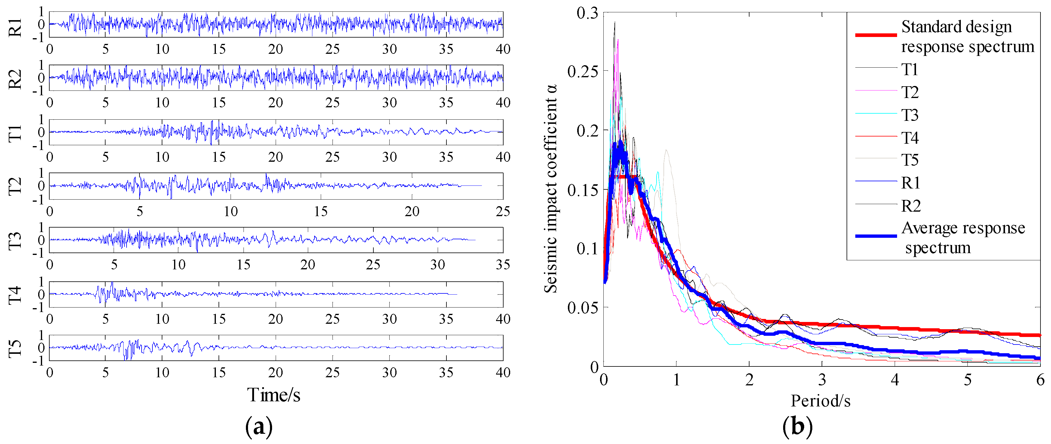
Elastic time–history analysis based on Ritz vectors (fast nonlinear analysis, i.e., FNA) is used, with 144 vibration modes selected. According to the requirements of the “Code for Seismic Design of Buildings” and the “Technical Specification for Seismic Energy Dissipation of Buildings” [1,2], 5 natural waves and 2 artificial waves are selected for time–history analysis, and the time–history curve, response spectrum curve, and comparison with the normative response spectrum are shown in Figure 3. Seismic wave records are normalized to peak amplitude, and when used, they are amplified to the corresponding peak amplitude according to different seismic levels using a scaling factor. However, the time axis of seismic wave records is not adjusted for scaling. In the numerical simulation analysis, the additional damping ratio of the structure, the force and displacement of the damper, the shear force and displacement of the floor, and other relevant indicators are selected based on the average value of the seven seismic waves.

3. Results and Discussion

3.1. Sensitivity Analysis of the Impact of Damping Parameters

In order to investigate the influence of parameters of the viscous damper (mainly damping coefficient C and damping exponent α) on the damping efficiency in frame shear wall structure, a comparative finite element analysis of two sets of parameters is conducted based on the information in Section 2.2.1 regarding damper parameters. The first set consists of damping coefficients of 60 kN/(mm/s)α with varying damping exponents. The second set consists of a damping exponent of 0.25 with varying damping coefficients, as detailed in Table 1.
After attaching viscous dampers, the damping efficiency of damper is usually measured by the magnitude of the additional damping ratio. The reduction ratio of the vertex displacement and base shear of the damping structure relative to the non-damped structure (the structure without viscous dampers) are studied, and the force and displacement of the damper themselves are also considered. The following analysis will be conducted in detail based on these aspects.

3.1.1. The Additional Damping Ratio

The additional damping ratio is one of the important indicators for measuring the damping efficiency in a structural system. Viscous dampers belong to the typical velocity-dependent damper. According to the current standards in China [1,2], the effective additional damping ratio provided by dampers to the structural system can be calculated using the following equation.
ξ d = j = 1 n W c j 4 π W s
where ξ d represents the additional effective damping ratio dampers provide to the structure; W c j is the energy dissipated by the jth dissipative component in the structure during one cycle of reciprocating motion with an inter-story displacement Δ u j ; n is the number of dampers; W s is the total strain energy of the energy dissipation and damping structure under the expected displacement.
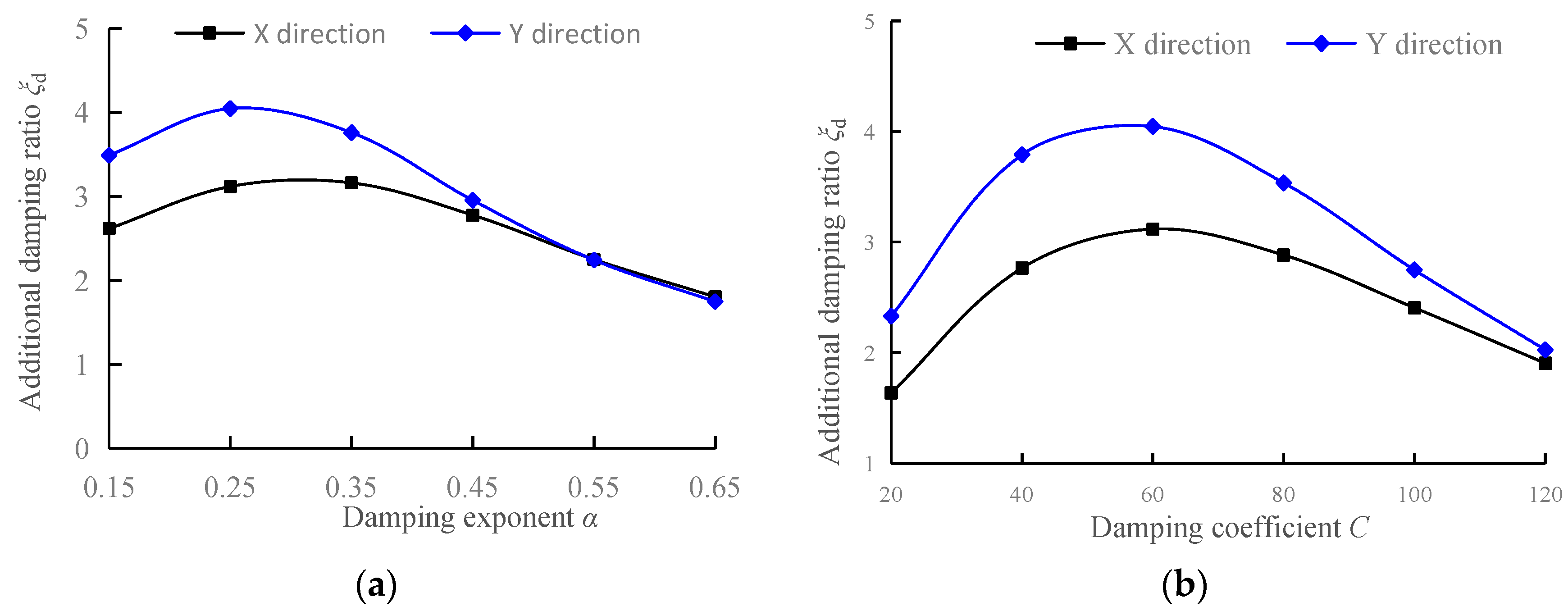
The additional damping ratios in the X and Y directions under two sets of parameters are calculated based on Equation (10), and the results are shown in Figure 4.
From the figure, it can be observed that the damping coefficient C remains constant at 60 kN/(mm/s)α and the damping exponent α varies between 0.15 and 0.65. The additional damping ratio of the structure increases initially and then decreases, ranging from 1.75% to 4.05%. The maximum additional damping ratio is achieved when α is between 0.25 and 0.35. When the damping exponent α remains constant at 0.25 and the damping coefficient C varies between 20 and 120 kN/(mm/s)0.25, the additional damping ratio of the structure also initially increases and then decreases, ranging from 1.63% to 4.05%. The maximum additional damping ratio is obtained when C is 60 kN/(mm/s)0.25.

3.1.2. The Reduction Rate of Vertex Displacement

The reduction rate of vertex displacement is also one of the important indicators for measuring the damping efficiency in a structural system. It is represented by the reduction rate of vertex displacement in the damping structure relative to that in the non-damped structure. The calculation expression is as follows.
μ u = u 0 u u 0 × 100 %
where μ u represents the reduction rate of vertex displacement, u 0 represents the vertex displacement in the non-damped structure, and u represents the vertex displacement in the damping structure.
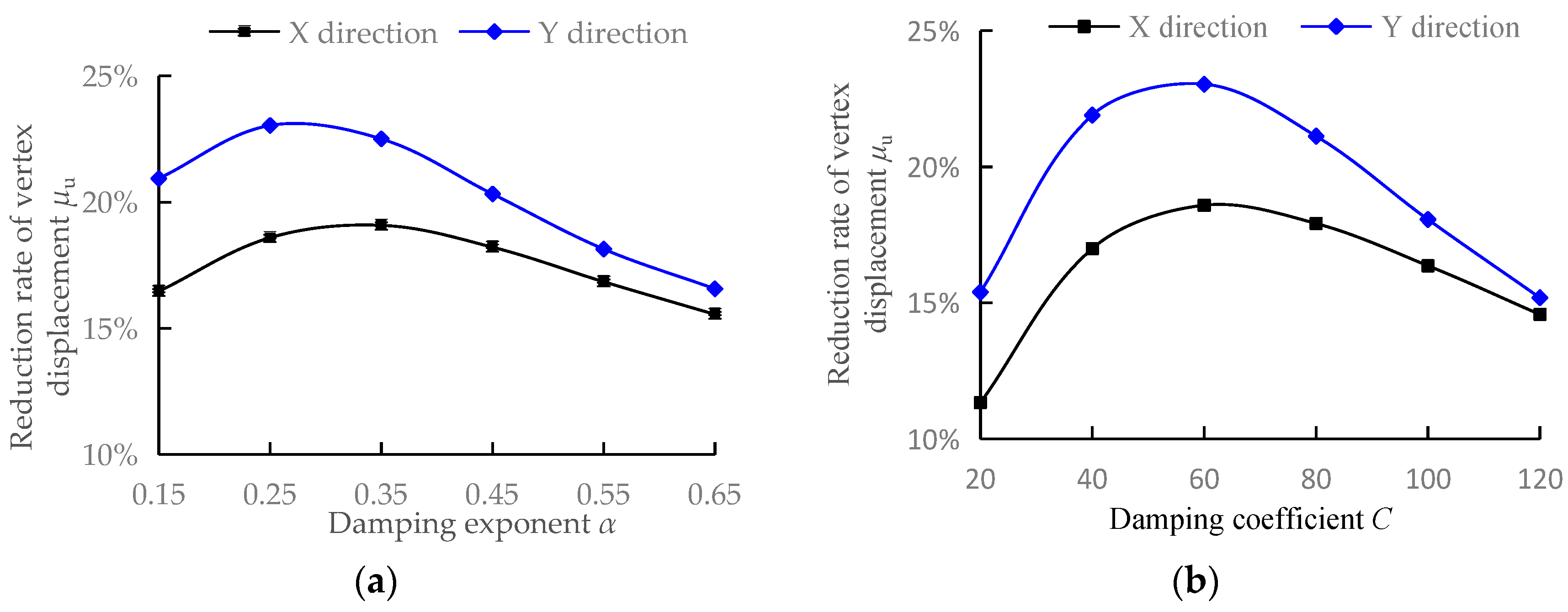
The reduction rates of vertex displacement in the X and Y directions of the structure are calculated for two sets of parameters according to Equation (11), as shown in Figure 5.
From the figure, it can be observed that when the damping coefficient C remains constant and the damping exponent α varies between 0.15 and 0.65, the reduction rate of vertex displacement increases initially and then decreases. Overall, there is not a significant difference in the reduction rate of vertex displacement, which ranges from 16% to 23%. The maximum reduction rate of vertex displacement is achieved when α is between 0.25 and 0.35. When the damping exponent α is fixed at 0.25 and the damping coefficient C varies between 20 and 120 kN/(mm/s)0.25, the reduction rate of vertex displacement first increases rapidly and then decreases slowly, ranging from 11% to 23%. The maximum reduction rate of vertex displacement is achieved when C is 60 kN/(mm/s)0.25.

3.1.3. The Reduction Rate of Base Shear

The base shear reduction rate is another important indicator for measuring the damping efficiency in a structural system. It is expressed by the ratio of the reduction in base shear for a structure with damping measure to the base shear without such measure. The calculation expression is as follows.
μ V = V 0 V V 0 × 100 %
In the equation, μ V represents the base shear reduction rate, V 0 represents the base shear of the non-damped structure, and V represents the base shear of the damping structure.
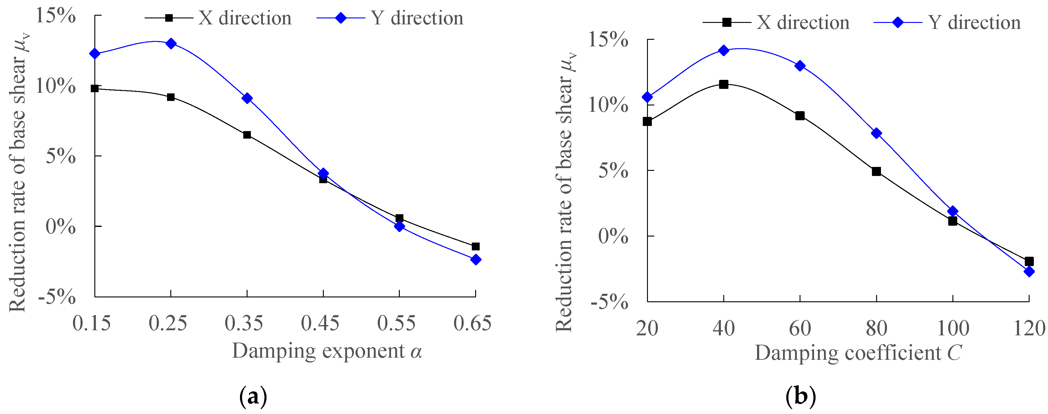
The base shear reduction rates in the X and Y directions are calculated according to Equation (12) for two sets of parameters, as shown in Figure 6.
From the graph, it can be observed that when the damping coefficient C remains constant at 60 kN/(mm/s)α, and the damping exponent α is adjusted between 0.15 and 0.65, the base shear reduction rate initially increases and then decreases, varying between −2% and 13%. The maximum base shear reduction rate is achieved when α = 0.25. When the damping exponent α is fixed at 0.25, and the damping coefficient C is adjusted between 20 and 120 kN/(mm/s)0.25, the base shear reduction rate also initially increases and then decreases, varying between −3% and 14%. The maximum base shear reduction rate is achieved when C = 40 kN/(mm/s)0.25.
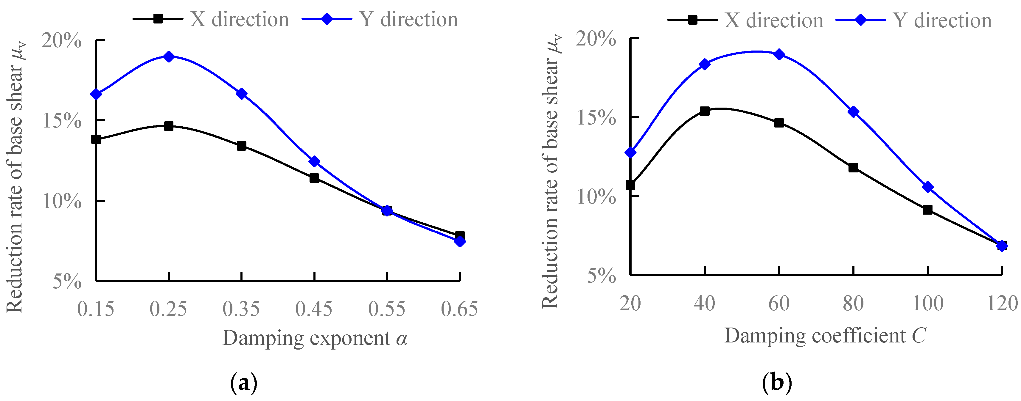
The aforementioned analysis of base shear includes the force of the bottom dampers. Therefore, negative values appear when calculating the base shear reduction rate, indicating an increase in base shear after the installation of additional dampers. However, the base shear of the structure itself does not change in this way. By deducting the force of the bottom dampers from the original base shear, a new base shear is obtained. The base shear reduction rates in the X and Y directions for two sets of parameters are calculated according to Equation (12), as shown in Figure 7.
From the graph, it can be observed that when the damping coefficient C remains constant at 60 kN/(mm/s)α, and the damping exponent α is adjusted between 0.15 and 0.65, the base shear reduction rate initially increases and then decreases, ranging from 7% to 19%. The maximum base shear reduction rate is achieved when α = 0.25. When the damping exponent α is fixed at 0.25, and the damping coefficient C is adjusted between 20 and 120 kN/(mm/s)0.25, the base shear reduction rate initially increases rapidly and then decreases slowly, ranging from 7% to 19%. The maximum base shear reduction rate is achieved when C = 40~60 kN/(mm/s)0.25.
Comparing Figure 6 and Figure 7, it can be seen that the base shear reduction rate significantly increases after deducting the force of the bottom dampers from the original base shear, and the pattern becomes more reasonable. Therefore, this method should be adopted to calculate the base shear reduction rate. Comparing Figure 5 and Figure 7, it can be observed that the base shear reduction rate is slightly smaller than the vertex displacement reduction rate.

3.1.4. The Inter-Story Displacement Utilization Rate

The inter-story displacement utilization ratio is commonly used to measure the damping efficiency in a structural system. It is expressed as the ratio between the displacement of the damping device in the damping structure and the displacement of the corresponding floor. The calculation expression is as follows.
η = u d u × 100 %
where η represents the inter-story displacement utilization rate; u represents the displacement of the floor where the damping device is located; u d represents the displacement of the damping device.
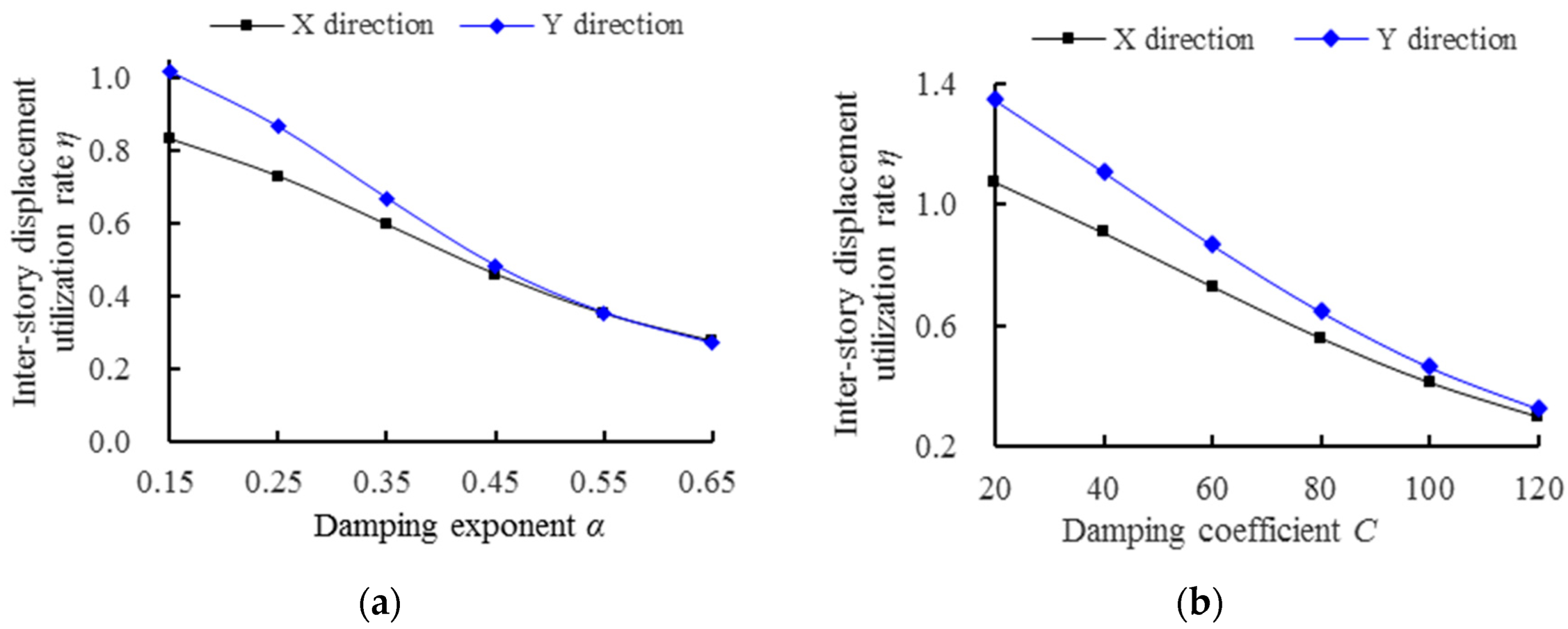
The inter-story displacement utilization rates in the X and Y directions of the structure are calculated based on Equation (13), as shown in Figure 8.
From the figure, it can be observed that when the damping coefficient C remains constant at 60 kN/(mm/s)α, the inter-story displacement utilization rate rapidly decreases from 1.02 to 0.27 as the damping exponent α is adjusted between 0.15 and 0.65. Similarly, when the damping exponent α remains constant at 0.25, the inter-story displacement utilization rate decreases from 1.35 to 0.30 as the damping coefficient C is adjusted between 20 and 120 kN/(mm/s)0.25. Both the damping coefficient and damping exponent have significant effects on the inter-story displacement utilization rate, with the damping coefficient having a more pronounced effect. The smaller inter-story displacement utilization rate indicates that the displacement of the damping device can make less use of the floor displacement, resulting in a poorer energy dissipation performance.

3.1.5. Damping Force and Displacement

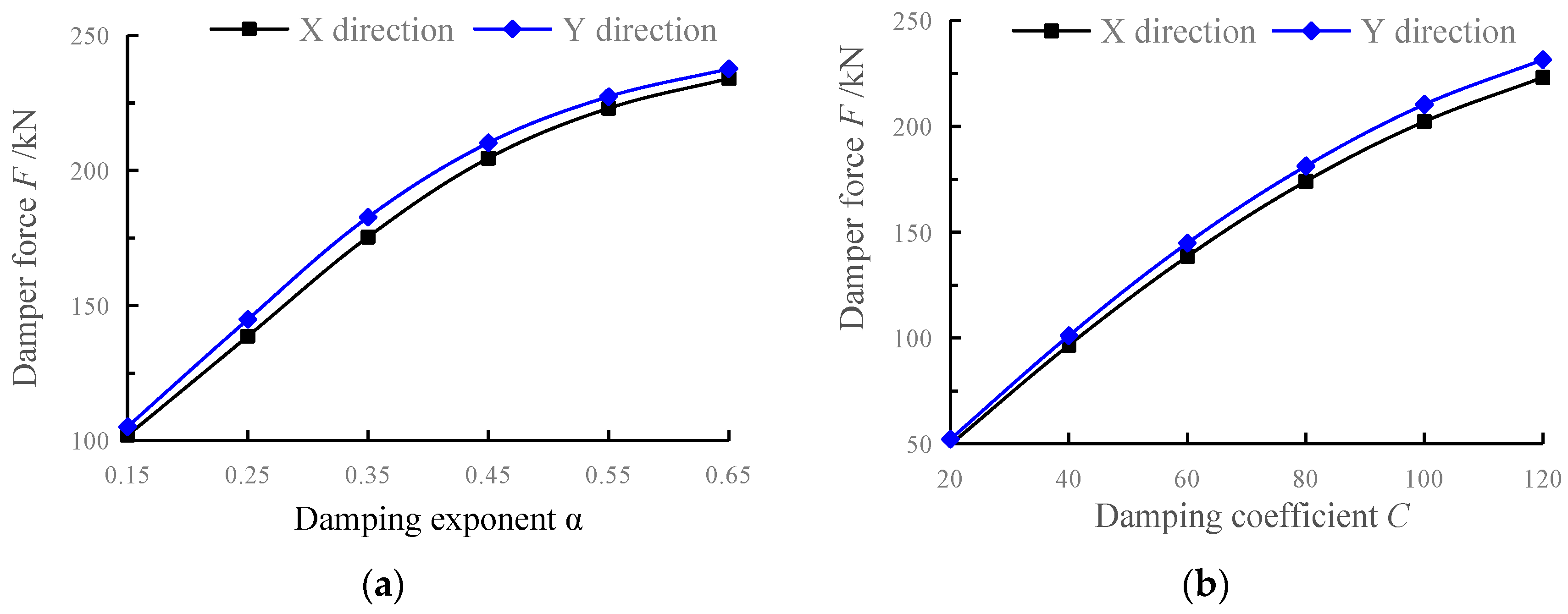
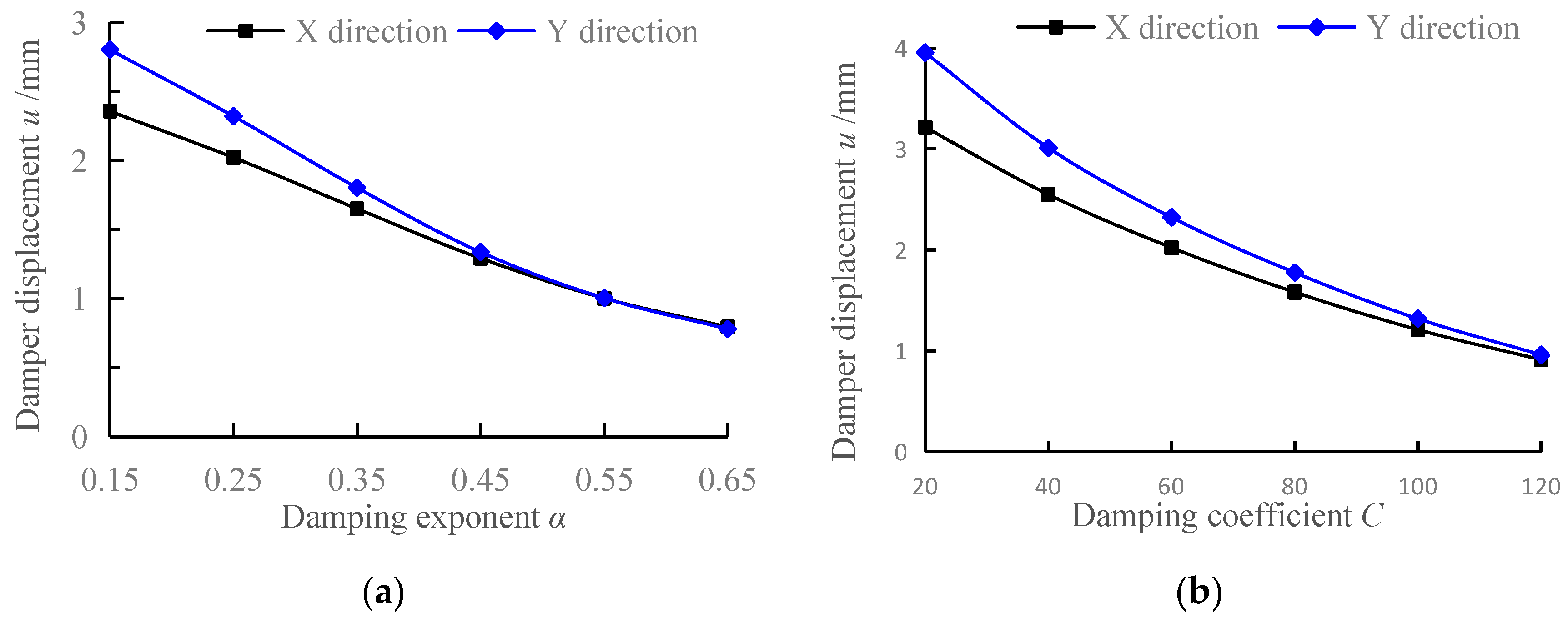
The force and displacement response of dampers allow it to dissipate energy, which is the reason for its ability to achieve a damping effect. The output force and displacement response of dampers vary greatly under different damper parameters. A higher output force and displacement result in more energy dissipation. However, the magnitude of the damper force has a significant impact on the damping structure, especially on the components connected to the damper. Therefore, a reasonable balance between the damper output force and displacement is required during the design of the damping structure. The damper output force and displacement for the X and Y directions of the structure under two sets of parameters are shown in Figure 9 and Figure 10, respectively.
From Figure 9 and Figure 10, it can be seen that the output force of dampers increases with the increase in the damping exponent and damping coefficient. The displacement of dampers decreases with the increase in the damping exponent and the damping coefficient. When the dynamic characteristics of structure X and Y directions are similar, the output force and displacement responses of the dampers are also similar. Therefore, in practical engineering applications, it is particularly important to balance the output of the damper. Excessive output of the damper will increase the burden on the supporting components of the damper, making the design of the supporting components difficult. On the other hand, insufficient output of the damper will result in lower energy dissipation, seriously affecting the damping effect of the structure.

3.2. Optimization of Parameters for Viscous Dampers and Flowchart for Damping Design

Optimization design of viscous dampers’ parameters for damping of frame shear wall structure based on response surface methodology and multivariate function extremum.

3.2.1. Response Surface Model

In the response surface model, the polynomial order directly affects the fitting accuracy of the model. When the order is too high, it is prone to “Runge’s phenomenon”, which reduces the accuracy of the response surface. On the other hand, a too low order cannot correctly reflect the nonlinear characteristics with implicit functional functions. Therefore, different basic expressions of response surface models are selected based on the curve laws of various indicators in the previous section.
In the precision test of the response surface model, the determination coefficient R2 exhibits values between 0 and 1, and the closer it is to 1, the higher the fitting accuracy. The significance level p value is calculated using the F-test method, and if p < 0.01, it indicates that the parameters of the response surface model are significant.
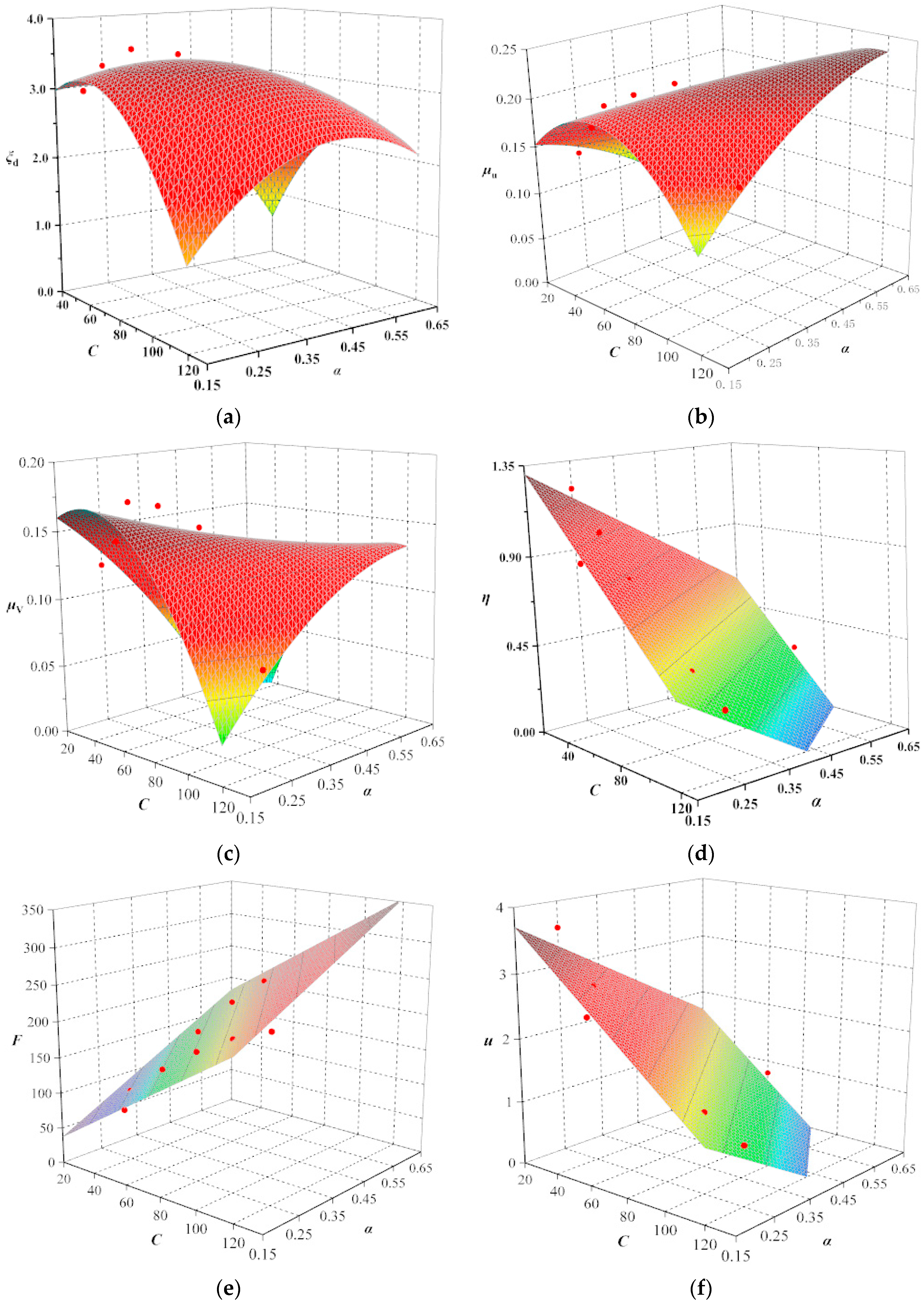
For convenience of simulation and expression, the average values of the corresponding indicators X-axis and Y-axis responses in the previous section are taken, and then the relationship between the damping coefficient and the damping exponent is examined. The surface fitting results of the seismic response for various indicators are shown in Table 2.
Referring to the fitting types of response surfaces corresponding to various damping indicators in Table 2, the fitting curves for the six indicators shown in Figure 11 are obtained. The red dots in the figure represent the target working condition sample points in Section 3.1. It can be seen from Table 2 that the response surface fitting surfaces of various indicators are in excellent agreement with the calculated results at the sample points, indicating excellent fitting effect.
From Figure 4 and Figure 11, it can be observed that the additional damping ratio, reduction rate of vertex displacement, and reduction rate of the base shear of the structure first increase and then decrease with the increase in damping coefficient C, and also first increase and then decrease with the increase in damping exponent α, but the rate of change is not consistent. The inter-story displacement utilization ratio and damper displacement decrease with the increase in both the damping coefficient and the damping exponent. The damper force increases with the increase in both the damping coefficient and the damping exponent. Therefore, it can be seen that there is no consistent or monotonic variation pattern in the response of different damping efficiency indicators of the structure, which is related to the values of the damper parameters C and α, showing a nonlinear surface variation pattern: response surface of additional damping ratio, response surface of vertex displacement reduction rate, and response surface of base shear reduction rate. As for the inter-story displacement utilization ratio, damper displacement, and damper output force, they show relatively simple linear surface variation patterns. Therefore, the influence pattern of different combinations of viscous damper parameters on the response of damping efficiency indicators is complex, and traditional sensitivity analysis methods struggle to comprehensively consider the combined effects of different damping efficiency indicators and obtain the optimal parameters.

3.2.2. Objective Function

In the above indicators of the damping efficiency, the focus is on analyzing the indicators that first increase and then decrease with the variation in the damper parameters (damping coefficient and damping exponent), i.e., the indicators that have extremum values, mainly including the additional damping ratio, the reduction rate of vertex displacement, and the reduction rate of base shear. Regarding the utilization ratio of inter-story displacement, it can be seen from the curve in Figure 8 that the smaller the damping coefficient and damping exponent, the greater the utilization ratio of inter-story displacement. The output force and displacement curves of the damper in Figure 9 to Figure 10 also approximately monotonically increase or decrease with the relationship with the damper parameters.
By using the linear weighting method, the three indicators with extremum values are linearly superimposed to obtain a response evaluation function that considers the combined influence of different damping efficiency indicators, i.e., the objective function. The weight coefficients of each indicator are determined based on the degree of influence of the damping efficiency indicator on the structural response. In this study, it is considered that the influence evaluations of the additional damping ratio, the reduction rate of vertex displacement, and the reduction rate of base shear on the structural response are equivalent, so they are assigned the same weight coefficients a, b, c, respectively. Therefore, the response evaluation function is expressed as shown in the equation.
S = a ξ d + b μ u + c μ V
where S is the response evaluation function (objective function) of the structure under the combined influence of different damping efficiency indicators. The weight coefficients, a, b, and c, are all set to 1.0. ξ d is the additional effective damping ratio provided by the damper; μ u is the reduction rate of vertex displacement of the damping structure; μ V is the reduction rate of the base shear of the damping structure. By optimizing Equation (14), the maximum value of the response S is obtained, which corresponds to the parameters of the viscous damper after the optimization design of the damping structure.

3.2.3. Analysis of Optimized Results

The objective function of Equation (14) is optimized with respect to the damping coefficient and the damping exponent as a bi-variate function. The specific steps follow those described in Equations (6)–(8) in Section 2.1.2. It is found that A < 0 and ACB2 > 0, indicating the existence of a maximum value. Based on the previous analysis, this maximum value is the maximum within the given range. The optimized values for the damping parameters are found to be (C, α) = (72, 0.32).
Substituting these optimal parameters into the actual engineering case, the additional damping ratio, vertex displacement reduction ratio, and base shear reduction ratio of the structure are obtained as shown in Table 3.
From Table 3, it can be seen that the optimal parameters (C, α) = (72, 0.32) are used for calculations in the actual engineering project in Section 2.2. The obtained damping indicator differs from the results calculated in Section 3.1 with damping parameters (60, 0.25), for example, the additional damping ratio index: ξd(60, 0.25) = 3.58%, ξd(72, 0.32) = 3.14% (taking the average value in the X and Y directions). It seems that the result of the optimal damping parameters (72, 0.32) is not as expected. The main reason for this is that the stiffness of the supporting damper components has a certain influence on the effectiveness of the damper parameters, which will be discussed in detail in the following content. In addition, the utilization rate of inter-story displacement is relatively low, indicating that the displacement of the damper is not fully utilized by the floor displacement, which is also related to the stiffness of the supporting damper components.
In fact, the effectiveness of the damper is to some extent influenced by the stiffness of the supporting damper components. Specifications [1,2] specifically stipulate that the stiffness of the supporting components of the linear viscous damper in the direction of energy dissipation should comply with Equation (15). Subsequently, using Equation (15) as a criterion, the support stiffness level is matched with the corresponding optimal damping parameters (72, 0.32) with the support stiffness level of the given damping parameters (60, 0.25).
K b 6 π C D / T 1
where Kb is the stiffness of the supporting components in the direction of energy dissipation (kN/m); T1 is the fundamental natural period of the damping structure (s); CD is the linear damping coefficient of the damper ( k N m 1 s 1 ), and for the nonlinear viscous damping coefficient, it needs to be converted into the equivalent linear viscous damping coefficient according to Equation (16) and satisfy the requirement of Equation (15).
C D = C e q = λ π ( ω A ) 1 α C α
In the equation, Ceq represents the equivalent linear viscous damping coefficient, which replaces CD in Equation (15); Cα represents the nonlinear viscous damping coefficient; ω is the circular frequency of the damping structure system; A is the displacement amplitude of the damper in the damping structure; α is the damping exponent; λ is the gamma function related to the damping exponent α, given by 22+αΓ2(1 + α/2)/Γ(2 + α).
According to Equations (15) and (16), the support component stiffness of the optimal damper parameters (72, 0.32) should be adjusted to a level equivalent to the parameters (60, 0.25). The support component stiffness needs to be amplified by a factor of 1.80, and its width should also be increased from 1500 mm to 2090 mm, while the thickness remains unchanged at 200 mm. Then, further analysis will be conducted. The results are presented in Table 4.
From Table 4, it can be seen that after considering the matching problem of the supported component stiffness under the optimal damper parameters, various damping performance indicators, especially the additional damping ratio, vertex displacement reduction rate, and base shear reduction rate, all significantly increase. The output force and displacement of the damper also increase significantly, leading to a significant increase in energy dissipation and a significant improvement in the damping efficiency of the structure. The establishment of the response surface model and the optimization of the objective function based on the above theoretically prove the existence of the optimal damping parameters. The calculation results in this table, based on the practical engineering case, demonstrate the feasibility of the optimal damping parameters from a practical perspective.

3.2.4. The Damping Design Flowchart

The application of viscous dampers in frame shear wall structures is investigated through traditional sensitivity analysis and response surface-based methods. The influence of damper coefficients and damper exponents on the structural seismic performance is studied in detail. A simple and easy-to-operate damping design flowchart is proposed, which can be used to complete the damping design of other additional viscous dampers in frame shear wall structures according to the idea and method presented in the flowchart. Therefore, it can provide important guidance and reference for designers in the future when conducting damping design of frame shear wall structures, as shown in Figure 12.

4. Conclusions

This paper focuses on the application of viscous dampers in frame shear wall structures and extensively investigates the influence of damper parameters on the damping efficiency of frame shear wall structures. It also proposes a damping design flowchart that takes into account the impact of damper parameters on the damping efficiency. The main conclusions are as follows:
(1)
The parameters within the range of damping coefficient 20~120 kN/(mm/s)α and damping exponent 0.15~0.65 are combined, and the traditional sensitivity analysis method is used to calculate various damping efficiency indicators. When the damping coefficient and damping exponent are approximately (60, 0.25), the additional damping ratio, reduction rate of vertex displacement, and reduction rate of base shear achieve relatively large values of 4.05%, 23%, and 19%, respectively. As the damping coefficient and damping exponent increase, the inter-story displacement utilization rate decreases from significantly greater than 1.0 to far less than 1.0, and the displacement of the damper decreases while the damping force increases. The study shows that the influence of different combinations of viscous damper parameters on the response of damping efficiency indicators is complex, and it is difficult for the traditional sensitivity analysis method to comprehensively consider the combined effects of different damping efficiency indicators to obtain the optimal parameters.
(2)
By explicitly formulating the relationship between viscous damper parameters and various damping efficiency indicators of the structural system using response surface methodology, and combining the F-test and coefficient of determination R2 to evaluate the fitting effect of the response surface function, high fitting accuracy and good predictability are achieved, making our model suitable as an optimization model.
(3)
The influence of support component stiffness on the damping efficiency indicators of the structure is significant. After the variation of damper parameters, it is advisable to match the corresponding support component stiffness according to the specifications in order to obtain the true results of various damping efficiency indicators under optimal parameters. After matching the stiffness of the supporting members, the additional damping ratios in the case increased from 2.91% and 3.38% to 4.50% and 5.70%, respectively, representing an approximately 55% increase. Other damping efficiency indicators also showed significant improvement. This pattern is applicable to other frame shear wall structures with additional viscous dampers.
(4)
A simple and easy-to-use “damping design flowchart considering the impact of damper parameters on the damping efficiency” is proposed. By following the idea and method presented in this flowchart, designers can complete the damping design of other frame shear wall structures with additional viscous dampers. This flowchart can provide important guidance and reference for future designers in conducting damping design for frame shear wall structures.

Author Contributions

Conceptualization, X.L. and X.Z.; methodology, X.L.; software, X.L.; validation, X.L., G.W. and X.Z.; formal analysis, X.L.; investigation, G.W.; resources, X.L.; data curation, X.L.; writing—original draft preparation, X.L.; writing—review and editing, X.L.; visualization, X.Z.; supervision, G.W.; project administration, X.L.; funding acquisition, X.L. All authors have read and agreed to the published version of the manuscript.

Funding

This research was funded by the Yunnan Provincial Basic Research Special Project (Grant No. 202101AU070059), the Foundation of Yunnan Provincial Educational Committee (No. 2022J0596) and the Research Project of Introducing Talents in Kunming University (No. XJ20210006).

Data Availability Statement

All the data utilized in the research has been fully presented in the paper. No additional data has been employed.

Conflicts of Interest

The authors declare no conflicts of interest.

References

  1. GB 50011-2016; Chinese Standard, Code for Seismic Design of Buildings. Chinese Architecture and Building Press: Beijing, China, 2016.
  2. JGJ 297-2013; Chinese Standard, Technical Specification for Seismic Energy Dissipation of Buildings. Chinese Architecture and Building Press: Beijing, China, 2013.
  3. Titirla, M.D. A state-of-the-art review of passive energy dissipation systems in steel braces. Buildings 2023, 13, 851. [Google Scholar] [CrossRef]
  4. Rayegani, A.; Nouri, G. Application of smart dampers for preventing of seismic pounding in isolated structures subjected to near-fault earthquakes. J. Earthq. Eng. 2020, 26, 4069–4084. [Google Scholar] [CrossRef]
  5. Rayegani, A.; Nouri, G. Seismic Collapse Probability and Life Cycle Cost Assessment of Isolated Structures Subjected to Pounding with Smart Hybrid Isolation Systems Using a Modified Fuzzy Based Controller. Structures 2022, 44, 30–41. [Google Scholar] [CrossRef]
  6. Zoccolini, L.; Bruschi, E.; Cattaneo, S.; Quaglini, V. Current trends in fluid viscous dampers with semi-active and adaptive behavior. Appl. Sci. 2023, 13, 10358. [Google Scholar] [CrossRef]
  7. Lin, W.H.; Chopra, A.K. Earthquake response of elastic SDF systems with nonlinear fluid viscous dampers. Earthq. Eng. Struct. D 2002, 31, 1623–1642. [Google Scholar] [CrossRef]
  8. Gherbi, A.; Belgasmia, M. A simplified design strategy of nonlinear fluid viscous dampers for MDOF structures. Iran. J. Sci. Technol. Trans. Civ. Eng. 2022, 46, 857–864. [Google Scholar] [CrossRef]
  9. Dargush, G.F.; Sant, R.S. Evolutionary aseismic design and retrofit of structures with passive energy dissipation. Earthq. Eng. Struct. D 2005, 34, 1601–1626. [Google Scholar] [CrossRef]
  10. Rayegani, A.; Soureshjani, O.K.; Alaee, S.A.M.; Mualla, I.H.; Nemati, F. Seismic performance of buildings equipped with four-joint rotational friction dampers in mainshock-aftershock sequences. J. Struct. Eng. 2024, 150, 12980. [Google Scholar] [CrossRef]
  11. Ding, J.; Wang, S.; Wu, H. Seismic performance analysis of viscous damping outrigger in super high-rise buildings. Struct. Des. Tall Spec. Build. 2018, 27, e1486. [Google Scholar] [CrossRef]
  12. Chen, P.; Wu, X. Investigations on the dynamic response of adjacent buildings connected by viscous dampers. Buildings 2022, 12, 1480. [Google Scholar] [CrossRef]
  13. De Souza Pippi, A.; Avila, S.M.; Doz, G. A review on the use of the inerter device in the structural coupling technique for adjacent building vibration control. Structures 2022, 42, 480–501. [Google Scholar] [CrossRef]
  14. Tubaldi, E. Dynamic behavior of adjacent buildings connected by linear viscous/viscoelastic dampers. Struct. Control Health Monit. 2015, 22, 1086–1102. [Google Scholar] [CrossRef]
  15. Palermo, M.; Silvestri, S. Damping reduction factors for adjacent buildings connected by viscous-viscous dampers. Soil. Dyn. Earthq. Eng. 2020, 138, 106323. [Google Scholar] [CrossRef]
  16. Kazemi, F.; Miari, M.; Jankowski, R. Investigating the effects of structural pounding on the seismic performance of adjacent RC and steel MRFs. Bull. Earthq. Eng. 2021, 19, 317–343. [Google Scholar] [CrossRef]
  17. Zhai, C.; Jiang, S.; Li, S.; Xie, L. Dimensional analysis of earthquake-induced pounding between adjacent inelastic MDOF buildings. Earthq. Eng. Eng. Vib. 2015, 14, 295–313. [Google Scholar] [CrossRef]
  18. Xu, W.; Du, D.; Wang, S.; Li, W. A new method to calculate additional damping ratio considering the effect of excitation frequency. Adv. Civ. Eng. 2020, 2020, 3172982. [Google Scholar] [CrossRef]
  19. Diotallevi, P.P.; Landi, L.; Dellavalle, A. A methodology for the direct assessment of the damping ratio of structures equipped with nonlinear viscous dampers. J. Earthq. Eng. 2012, 16, 350–373. [Google Scholar] [CrossRef]
  20. Hwang, J.S.; Huang, Y.N.; Yi, S.L.; Song, Y.H. Design formulations for supplemental viscous dampers to building structures. J. Struct. Eng. 2008, 134, 22–31. [Google Scholar] [CrossRef]
  21. Rama, R.K.; Ansu, M.; Iyer, N.R. A methodology of design for seismic performance enhancement of buildings using viscous fluid dampers. Struct. Control Health Monit. 2014, 21, 342–355. [Google Scholar] [CrossRef]
  22. Xie, Y.; Zhang, J.; Xi, W. Effectiveness evaluation and optimal design of nonlinear viscous dampers for inelastic structures under pulse-type ground motions. Earthq. Eng. Struct. D 2018, 47, 2802–2820. [Google Scholar] [CrossRef]
  23. Occhiuzzi, A. Additional viscous dampers for civil structures: Analysis of design methods based on effective evaluation of modal damping ratios. Eng. Struct. 2009, 31, 1093–1101. [Google Scholar] [CrossRef]
  24. Singh, M.P.; Moreschi, L.M. Optimal seismic response control with dampers. Earthq. Eng. Struct. D 2001, 30, 553–572. [Google Scholar] [CrossRef]
  25. Aguirre, J.J.; Almazan, J.L.; Paul, C.J. Optimal control of linear and nonlinear asymmetric structures by means of passive energy dampers. Earthq. Eng. Struct. D 2013, 42, 377–395. [Google Scholar] [CrossRef]
  26. Lopez, G.D. A simple method for the design of optimal damper configurations in MDOF structures. Earthq. Spectra 2001, 17, 387–398. [Google Scholar]
  27. Takewaki, I. Optimal damper placement for minimum transfer functions. Earthq. Eng. Struct. D 1997, 26, 1113–1124. [Google Scholar] [CrossRef]
  28. Takewaki, I. Optimal damper placement for critical excitation. Probabilist. Eng. Mech. 2000, 15, 317–325. [Google Scholar] [CrossRef]
  29. Lin, T.K.; Hwang, J.S.; Chen, K.H. Optimal distribution of damping coefficients for viscous dampers in buildings. Int. J. Struct. Stab. Dyn. 2017, 17, 1750054. [Google Scholar] [CrossRef]
  30. Pollini, N.; Lavan, O.; Amir, O. Minimum-cost optimization of nonlinear fluid viscous dampers and their supporting members for seismic retrofitting. Earthq. Eng. Struct. D 2017, 46, 1941–1961. [Google Scholar] [CrossRef]
  31. Parcianello, E.; Chisari, C.; Amadio, C. Optimal design of nonlinear viscous dampers for frame structures. Soil. Dyn. Earthq. Eng. 2017, 100, 257–260. [Google Scholar] [CrossRef]
  32. Domenico, D.D.; Hajirasouliha, I. Multi-level performance-based design optimisation of steel frames with nonlinear viscous dampers. Bull. Earthq. Eng. 2021, 19, 5015–5049. [Google Scholar] [CrossRef]
  33. Lavan, O.; Amir, O. Simultaneous topology and sizing optimization of viscous dampers in seismic retrofitting of 3D irregular frame structures. Earthq. Eng. Struct. D 2014, 43, 1325–1342. [Google Scholar] [CrossRef]
  34. Tubaldi, E.; Kougioumtzoglou, I.A. Nonstationary stochastic response of structural systems equipped with nonlinear viscous dampers under seismic excitation. Earthq. Eng. Struct. D 2015, 44, 121–138. [Google Scholar] [CrossRef]
  35. Zhang, Y.; Xu, W.; Du, D.; Wang, S. Stochastic optimization of dissipation structures based on lyapunov differential equations and the full stress design method. Buildings 2023, 13, 665. [Google Scholar] [CrossRef]
  36. Su, C.; Li, B.; Chen, T.; Dai, X. Stochastic optimal design of nonlinear viscous dampers for large-scale structures subjected to non-stationary seismic excitations based on dimension-reduced explicit method. Eng. Struct. 2018, 175, 217–230. [Google Scholar] [CrossRef]
  37. Tubaldi, E.; Ragni, L.; Dall’Asta, A. Probabilistic seismic response assessment of linear systems equipped with nonlinear viscous dampers. Earthq. Eng. Struct. D 2015, 44, 101–120. [Google Scholar] [CrossRef]
  38. Rodolfo, J.T.G.; Yeudy, F.V.A.; Ramon, G.D. Probabilistic estimation of the dynamic response of high-rise buildings via transfer functions. Eng. Struct. 2024, 302, 117299. [Google Scholar]
  39. Worden, K.; Cross, E.J. On switching response surface models, with applications to the structural health monitoring of bridges. Mech. Syst. Signal Process. 2018, 98, 139–156. [Google Scholar] [CrossRef]
  40. Deng, L.; Cai, C.S. Bridge model updating using response surface method and genetic algorithm. J. Bridge Eng. 2010, 15, 553–564. [Google Scholar] [CrossRef]
  41. Lan, X.; Pan, W.; Zhang, L.; Yu, W.; Wu, K. Application and research of viscous fluid damper in frame structure. Sichuan Build. Sci. 2022, 48, 10–17. (In Chinese) [Google Scholar] [CrossRef]
  42. Aydin, E.; Boduroglu, M.H.; Guney, D. Optimal damper distribution for seismic rehabilitation of planar building structures. Eng. Struct. 2007, 29, 176–185. [Google Scholar] [CrossRef]
Figure 1. Layout diagram of dampers and calculation model of damping structure: (a) the layout diagram of dampers; (b) the calculation model of damping structure.
Buildings 14 00497 g001
Figure 2. Maxwell mechanical model.
Buildings 14 00497 g002
Figure 3. Seismic wave time–history curves and response spectrum curves: (a) the time–history curves; (b) comparison of response spectrum curves.
Buildings 14 00497 g003
Figure 4. The curves of additional damping ratio: (a) the first set of parameters; (b) the second set of parameters.
Buildings 14 00497 g004
Figure 5. The curves of vertex displacement reduction rate: (a) the first set of parameters; (b) the second set of parameters.
Buildings 14 00497 g005
Figure 6. The curves of base shear reduction rate: (a) the first set of parameters; (b) the second set of parameters.
Buildings 14 00497 g006
Figure 7. The curves of base shear reduction rate (excluding damper output force): (a) the first set of parameters; (b) the second set of parameters.
Buildings 14 00497 g007
Figure 8. The curves of inter-story displacement utilization rate: (a) the first set of parameters; (b) the second set of parameters.
Buildings 14 00497 g008
Figure 9. The curves of damper output force: (a) the first set of parameters; (b) the second set of parameters.
Buildings 14 00497 g009
Figure 10. The curves of damper displacement: (a) the first set of parameters; (b) the second set of parameters.
Buildings 14 00497 g010
Figure 11. The response surface fitting of each indicator: (a) additional damping ratio; (b) reduction rate of vertex displacement; (c) reduction rate of base shear; (d) inter-story displacement utilization rate; (e) damper force; (f) damper displacement.
Buildings 14 00497 g011
Figure 12. Damping design flowchart considering the impact of damper parameters on damping efficiency.
Buildings 14 00497 g012
Table 1. The damper parameters.
The First Set of ParametersThe Second Set of Parameters
Serial NumberDamping Coefficient CDamping Exponent αSerial NumberDamping Coefficient CDamping Exponent α
1600.151200.25
2600.252400.25
3600.353600.25
4600.454800.25
5600.5551000.25
6600.6561200.25
Table 2. Seismic response surface fitting results.
IndicatorsResponse Surface TypespR2
Additional damping ratio ξdPoly2D<0.00010.917
Reduction rate of vertex displacement μuPoly2D<0.00010.900
Reduction rate of base shear μVPoly2D<0.00010.901
Inter-story displacement utilization rate ηPlane<0.00010.988
Damper force F/kNPlane<0.00010.970
Damper displacement u/mmPlane<0.00010.973
Note: The response surface types are the types of nonlinear surface fitting in Origin2017, where Poly2D represents a second-order polynomial for two variables, and Plane represents a first-order polynomial for two variables.
Table 3. Summary of damping indicators under optimal parameters.
IndicatorsX DirectionY Direction
Additional damping ratio ξd2.91%3.38%
Reduction rate of vertex displacement μu18%21%
Reduction rate of base shear μV12%14%
Inter-story displacement utilization rate η0.530.59
Damper force F/kN186194
Damper displacement u/mm1.481.61
Table 4. Summary of optimal parameters damping indicators after stiffness matching.
IndicatorsX DirectionY Direction
Additional damping ratio ξd4.50%5.70%
Reduction rate of vertex displacement μu25%30%
Reduction rate of base shear μV19%24%
Inter-story displacement utilization rate η0.700.81
Damper force F/kN199209
Damper displacement u/mm1.791.97
Disclaimer/Publisher’s Note: The statements, opinions and data contained in all publications are solely those of the individual author(s) and contributor(s) and not of MDPI and/or the editor(s). MDPI and/or the editor(s) disclaim responsibility for any injury to people or property resulting from any ideas, methods, instructions or products referred to in the content.