
Seismic Isolation of Fragile Pole-Type Structures by Rocking with Base Restraints

1
School of Civil and Resource Engineering, University of Science and Technology Beijing, Beijing 100083, China
2
Research Institute of Macro-Safety Science, University of Science and Technology Beijing, Beijing 100083, China
3
China Electric Power Research Institute, Beijing 100055, China
4
Department of Infrastructure Engineering, The University of Melbourne, Melbourne, VIC 3010, Australia
*
Author to whom correspondence should be addressed.
Buildings 2024, 14(4), 1176; https://doi.org/10.3390/buildings14041176
Submission received: 19 March 2024
/
Revised: 5 April 2024
/
Accepted: 16 April 2024
/
Published: 21 April 2024
(This article belongs to the Special Issue Advances and Applications in Structural Vibration Control)
Abstract
:Pole-type structures are vulnerable to earthquake events due to their slender shapes, particularly porcelain cylindrical equipment in electrical substations, which has inherent fragility and low strength in its materials. Traditional base isolation designs configure the bottom of the pole-type equipment as hinges with restraints. It fully relies on the restrainers to re-center the pole-type equipment, posing a risk of tilting and functionality failure after earthquakes. This study proposes a solution to this challenge by introducing a restrained rocking mechanism at the base of the structure. The design leverages the self-centering nature of rocking motion and uses restrainers to control the amplitude of rotation. Hence, it can effectively avoid tilting of the pole-type structures after earthquakes. Experimental investigations conducted on a 1:1 full-scale specimen revealed that the proposed restrained rocking design can achieve a reduction in seismic internal forces of over 50% while maintaining equipment in an upright position. Furthermore, an analytical model for the proposed isolation system of pole structures was developed and validated through comparison with experimental results. This paper introduces a novel solution for seismic isolation of pole-type structures through restrained rocking, specifically addressing the research gap regarding a reliable self-centering mechanism under seismic excitation. This advancement significantly enhances the seismic resilience of fragile pole-type structures and provides practical design methodologies for the seismic isolation of slender structures.
1. Introduction
Pole-type structures are commonly engineered to withstand moderate loads at considerable heights. This category of structures encompasses a variety of utility poles, such as electricity poles, flagpoles, communication facility poles, and overhead antennas. Typically, these structures are constructed using materials such as timber, steel tubes, or steel-reinforced concrete. Despite the supported loads being significantly lower than their own weight, the inherent self-weight and slender profile render these pole-type structures susceptible to lateral forces induced by seismic events [1,2] or wind loads [3,4]. Consequently, various efforts have been made to enhance the flexural strength of the pole-type structures [5,6].
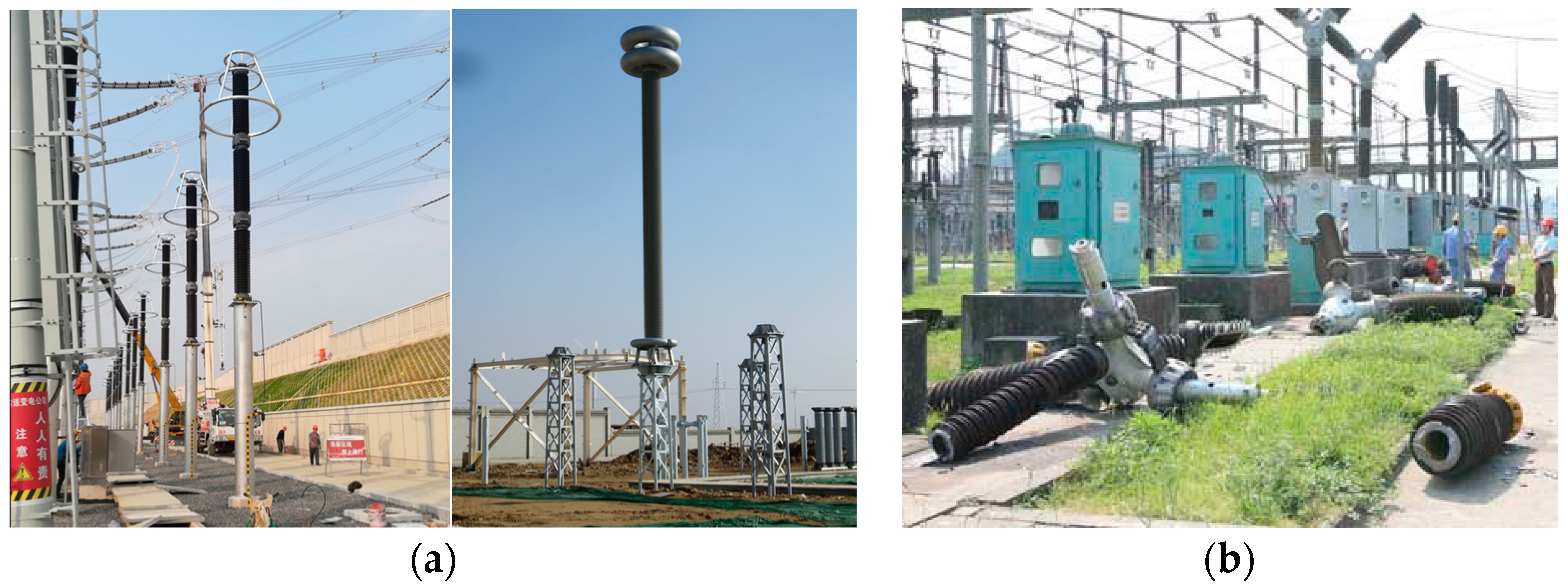
As illustrated in Figure 1a, cylindrical equipment within electric power substations represents an example of pole-type structures. The cylindrical electrical equipment comprises an array of insulators that support and house electrical components and conductors [7]. To ensure an adequate ground insulation distance, pole-type equipment in high-voltage substations can be more than ten meters in height, with length-to-diameter ratios of up to 1:20 [7]. Porcelain materials have excellent electrical insulation performance and are resistant to environmental corrosion, making them the preferred choice for forming the structural elements of cylindrical electrical equipment. As depicted in Figure 1a, hollow core insulators are formed by porcelain bushings, with both ends connected to metal flanges, and multiple insulators are assembled to create a piece of equipment. The electrical components housed within the hollow core insulators serve as non-structural parts.
Porcelain materials are characterized by low strength and brittleness, rendering them susceptible to brittle fracture even under low tensile stress [8,9]. Additionally, porcelain materials have a relatively high density, slightly exceeding that of concrete, and the electrical components housed within add considerable weight to the equipment. Given their brittle nature, substantial weight, and tall, slender profiles, the seismic resilience of pole-type cylindrical electrical equipment is compromised. Various types of pole-type electrical equipment, such as transformer bushings [10,11], surge arresters [12], capacitor voltage transformers [13], and post insulators [14,15], have been observed to be damaged during major earthquakes in recent decades [16,17,18,19], adversely affecting essential power supplies in the aftermath of these earthquakes [20,21,22]. Figure 1b illustrates the extensive damage to porcelain cylindrical electrical equipment during the 2008 Wenchuan earthquake. While glass fiber composite materials [23] can be employed as substitutes for porcelain in insulator tubes, challenges related to inadequate bending strength at connections persist [24]. Furthermore, replacing insulators necessitates repeated electrical design and verification efforts, incurring significant costs.
Figure 1.
Example of seismic fragile pole-type equipment in engineering (photo by the author) and damage of an electrical substation within the Sichuan electric power grid during the 2008 Wenchuan earthquake (cited from [25]). (a) Pole-type cylindrical equipment; (b) Earthquake damage.
Figure 1.
Example of seismic fragile pole-type equipment in engineering (photo by the author) and damage of an electrical substation within the Sichuan electric power grid during the 2008 Wenchuan earthquake (cited from [25]). (a) Pole-type cylindrical equipment; (b) Earthquake damage.

Given the aforementioned considerations, the optimal approach for seismic enhancement of cylindrical equipment is seismic isolation at the base. In relevant studies, the base of pole-type equipment is engineered to be a rotational hinge in order to achieve isolation objectives [26,27]. Additionally, energy dissipation devices, such as metallic yielding dampers [28,29] or wire rope isolators [30,31,32], are integrated as restraints to control the rotation at the base hinge. This method, which mitigates base moments and prolongs the structural vibration period, has demonstrated effectiveness in enhancing seismic resistance. However, it is crucial to note that restoring moments at the bottom are provided by restraint elements. This approach necessitates the restraint elements to maintain a recoverable state; otherwise, post-seismic residual deformations may lead to structural tilting and subsequent functional or structural failures. The absence of a reliable self-centering mechanism for seismic isolation of pole-type equipment represents a notable research gap. Addressing this gap is the primary objective of this study, which has the potential to further enhance the seismic resilience of such equipment.
The rocking motion of structures under horizontal base excitation [33] inherently possesses self-centering capabilities owing to the gravitational effects after uplifting. Seismic protection by rocking has been exemplified by the stone pillars in ancient temple architecture, which have withstood earthquakes over hundreds of years [34,35]. In recent decades, leveraging rocking action for seismic isolation design has seen significant application in building and bridge engineering, such as the use of rocking walls (or rocking shallow foundations) in buildings [36,37,38,39] and rocking piers in bridges [40,41,42,43]. Various types of restraints [44,45,46,47] have been proposed to mitigate the overturning hazard of rocking systems.
Incorporating restrained rocking mechanisms to achieve reliable rocking isolation designs for pole-type electrical equipment is the primary focus of this study. Equally important is the development of an analytical model as an analysis method for the restrained rocking design of such facilities. Previous studies have proposed analytical models for the rocking response of flexible structures [48,49,50,51,52], which serve as the basis for the models presented in this paper. Additionally, a significant contribution of this paper lies in the validation of the isolation design through shaking table tests of full-scale electrical equipment, the results of which will be extensively reported.
The novelty of the paper lies in the restrained rocking mechanism for seismic isolation of pole-type cylindrical electrical equipment. While previous studies have explored seismic isolation methods involving rotational hinges and energy dissipation devices, the proposed design integrates rocking interfaces, rotational restraint devices, and stopples to allow for a controlled rocking motion of the structure under seismic excitation while limiting excessive rotation. This innovative design addresses the lack of a reliable self-centering mechanism in existing seismic isolation methods for pole-type equipment, representing a significant advancement in enhancing the seismic resilience of such structures.
In this paper, Section 2 will introduce the design concept of restrained rocking isolation for pole-type structures. The analytical model of the proposed system will be developed in Section 3. The validation of the restrained rocking design for a full-scale high-voltage surge arrester will be presented in Section 4, and Section 5 will conduct a seismic response analysis to explore the seismic response patterns of the proposed design.
2. Conceptual Development
The aspect ratio of pole-type structures typically ranges from 1:10 to 1:20. According to previous experimental research [12], pole-type electrical equipment primarily experiences bending loads during seismic events, leading to significant tensile stress at the base. Consequently, implementing base shear isolation becomes challenging. The high tensile stress at the base necessitates horizontal shear isolation devices with a robust capacity for tensile resistance. However, common solutions for base shear isolation, such as friction pendulums or lead-core rubber bearings, lack sufficient tensile resistance in the vertical direction. Therefore, a rocking motion damping approach is considered more suitable for pole-type structures.
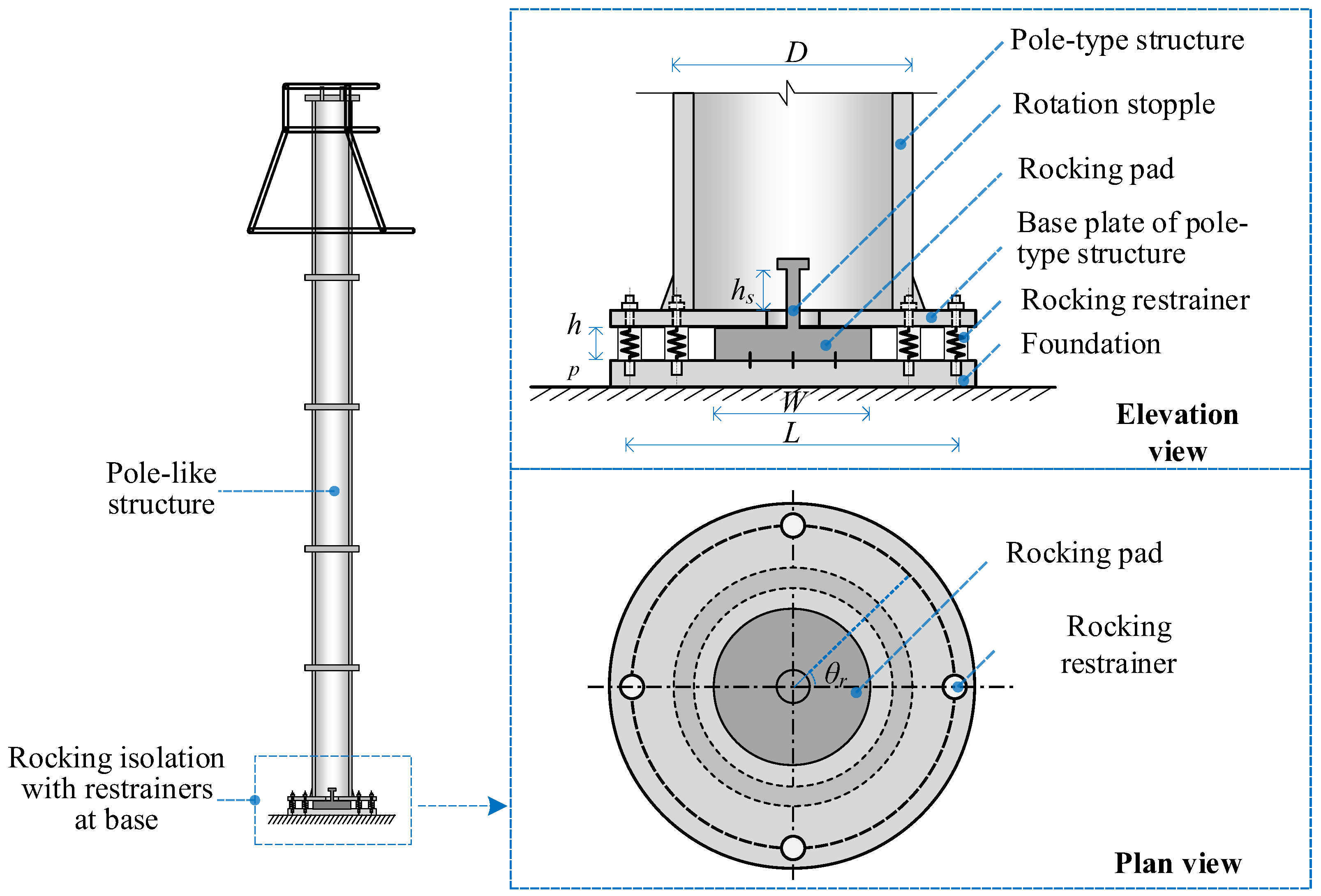
The design of restrained rocking isolation for pole-type structures in this study encompasses three main parts: rocking interfaces set at the base, rotational restraint devices circularly arranged at the base, and stopples set to prevent excessive rotation. These parts are compactly located between the base of the structure and the foundation (or elevation podium). The design is shown in Figure 2.
The isolation design in this study introduces a rocking mechanism at the base that allows the structure to undergo rocking motions under horizontal seismic excitation, as depicted in Figure 3. Unlike setting a hinge at the base in which the supporting block functions as a part of the base hinge [29], the rocking pads are set to provide an adjustable contact surface of width W (the diameter of the contact circle). Reducing the width W tends to make the structure more conducive to uplift, while increasing W enables the structure to enter a rocking state under larger base excitation. Another parameter of the rocking pad is the height hp, which should be coordinated with the initial length of the restrainers and its expected deformation during an earthquake event.
The rocking restrainers are arranged around the base of the structure, as shown in Figure 2, with the lower end fixed to the base and the upper end connected to the bottom plate of the pole-type structure. The example in Figure 2 shows eight evenly spaced restrainers, and its number can vary in different cases. The diameter D of the installation position needs to be selected carefully. A larger diameter D will result in a larger moment arm for restraining rocking motion and larger deformations in a certain rotation. When D is small, the deformation of the restrainer decreases, but larger force is required for restraining rocking.
The level arm of the circularly arranged restrainers relative to the pivot point is not constant during the rocking motion. For a given restrainer, the level arm is larger in the tension phases as compared to the compression phases. Additionally, among the restrainers, the majority are under tension, with only a few experiencing compression, as depicted in Figure 3. This force distribution characteristic of rocking restrainers is beneficial in reducing the demand on the height of rocking pads. Moreover, it facilitates the utilization of common springs as restrainers, which typically exhibit a large tensile stroke and a small compressive stroke. Figure 4 outlines the hysteresis relationships of various restrainers, such as linear springs, elasto-plastic elements, and yielding elements using the Wen model. Although not explicitly listed, restrainers with viscous damping can also be adopted.
In the design of restrained rocking isolation, it is necessary to implement stopples to limit the maximum rotation of the pole-structure within a certain range. The rotation stopples can be integrated with the rocking pad; for instance, it can be placed at the midpoint of the rocking pad, as shown in Figure 2. The length of the stopple (i.e., hs) restricts rotation within the range of arctan (2hs/W). The rotation limit can be set according to the maximum allowable inclination of the structure during earthquakes, and, in normal cases, the restrainers, rather than stopples, can keep the rotation within the limit so that the stopples become an additional safeguard against overturning.
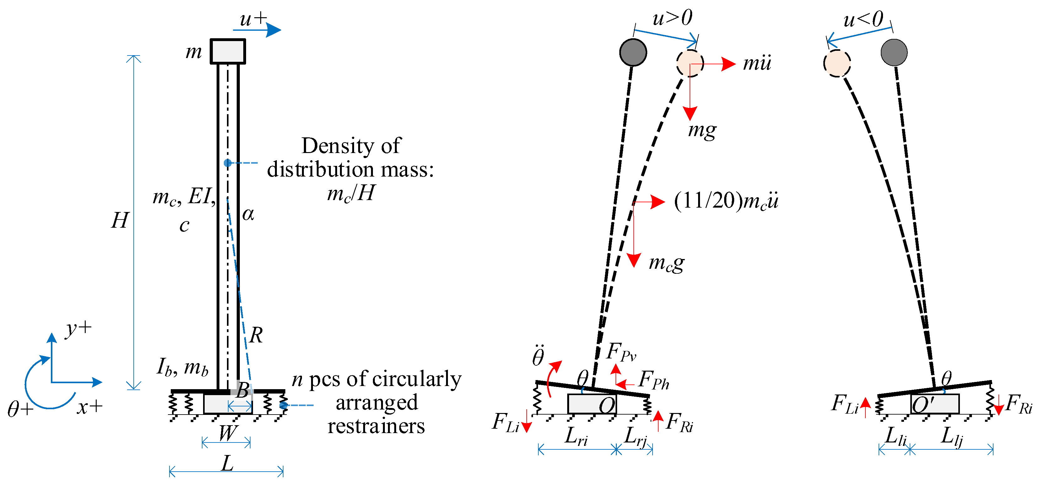
Figure 3 specifies the positive direction of rotation in the analysis. The structure rotates around the right-side point O of the rocking pad at a given time, t, and the rotation is represented by θ(t), which is a positive value. The level arm of ith the restrainer is expressed as:
in which LRi represents the lever arm of the ith restrainer relative to the rotation point and Lri denotes the lever arm when the rotation point is on the right. When the structure rotates around the left-side point O′, θ(t) is negative and the level arm of the restrainer is:
in which LRi represents the lever arm of the ith rocking restrainer relative to the rotation point O′ on the left. The values of Lri and Lli are contingent upon the distance of the restrainer relative to the rotation point, as depicted in Figure 3. The deformation of the restrainer is expressed as:
LRi = Lri, (i = 1, 2, …, n)
LRi = Lli, (i = 1, 2, …, n)
The corresponding restraining forces are determined based on the constitutive relationship of the restrainers. When the loading and unloading paths of the restrainers are consistent, as illustrated in Figure 4a,b, they can be represented as:
In cases where the loading and unloading paths of the restrainers are exhibiting hysteretic behaviour, is dependent on both the current deformation and the loading history. It also necessitates analysis combined with hysteresis relationships, as in the case shown in Figure 4c.
The total restoring moment of the restrainers, , is given by:
In addition to the restoring force from the restrainers, it is important to note that additional restoring moments can be generated from the rocking structure under the gravitational effects, ,
in which u(h,t) denotes the elastic displacement of the structure at height h.
3. Dynamics Modeling
The pole-type structure is simplified as a beam with a uniform cross-section, considering bending deformation as dominant and neglecting shear deformation. The sectional bending modulus of the column is denoted by EI, and the height of the column is H. The column is assumed to have a uniformly distributed mass with a mass density of mc/H. An additional mass m is added to the top to represent the supported load.
The fundamental period of pole-type equipment in electrical substations is typically within 0.8 s, placing it within or near the resonant period range of earthquake excitations. Consequently, the seismic response of pole-type equipment is predominantly governed by its first vibration mode. In former studies by the author on the shaking table test of pole-type electrical equipment with fixed bases, including the testing of surge arresters, post insulators and capacitor voltage transformers [7], it was demonstrated that the seismic response of the equipment primarily exhibited the first-order bending mode [12]. The shear deformation of the slender pole-type equipment is negligible considering the small cross-sectional dimensions compared to their length; therefore, it could be modelled by an Euler−Bernoulli beam with a damping coefficient c. The first-order mode shape of the cantilever column can be described by the following equation [53]:
With a fixed base, the frequency of the structure is given by:
It is important to highlight that, for pole-type structures with fundamental periods significantly longer than the resonant period range of earthquake excitations, the effectiveness of base isolation might be compromised due to the contribution of higher vibration modes [54,55]. While the exploration of seismic isolation methods for such flexural pole-type structures holds significance, it falls beyond the scope of this paper and warrants further research.
For the restrained rocking design in Section 2, the width of the rocking pad at the bottom of the structure is denoted as W, and the characteristic angle of the rocking structure is α, which equals arctan (W/H). There are n restrainers at the base, evenly distributed on a circle with diameter D. When the structure undergoes rocking vibrations, the system has two degrees of freedom: the rocking rotation degree of freedom (DOF) θ around the pivot point (O or O′) and the translational DOF representing the deformation at top u, as shown in Figure 5. The system forms a dynamic equilibrium in the rotational and horizontal directions under the action of gravity, inertia forces, and forces of restrainers.
The process of the rocking vibration of the pole-type structure, as shown in Figure 6, is analyzed here. In the initial state of rest, both rotation θ and translational deformation u are zero. Under seismic excitation, the structure undergoes lateral displacement first and responds like a fixed-base SDOF system. It does not rotate until the lateral displacement reaches a critical value . The can be obtained by referring to the state where an equivalent lateral force acting at the top of the cantilever structure produces the same moment as that of the gravity of the structure [56], which is:
After that, the system undergoes rotation, resulting in a state of 2DOF. The occurrence of rotation produces a deformation of the rocking restrainers. The vibration frequency of translational deformation shifts due to the supporting conditions changing from a fixed base to pivoting rotation [52]. Under the combined restoring moment from gravity and the rocking restrainer, the rocking rotation of the structure will return to zero after a cycle, and rocking pounding will occur. In this study, the Vertical Velocity Energy Loss (VVEL) model [52] is adopted to update the translational velocity and rotational velocity after pounding. It assumes that the energy of the vertical motion component is completely consumed while the energy of the horizontal motion remains unchanged, which is:
After the rocking pounding, the pole-type structure enters the SDOF state again and another cycle continues.
In a 2DOF state, both the angular acceleration and the translational acceleration will affect the dynamic balance in the translational direction and rotational direction. Analyzing from the perspective of dynamic equilibrium of forces and moments can be complex. Alternatively, analyzing the system dynamics from an energy perspective using the Lagrange equation is more straightforward.
The total kinetic energy E in the system is formed from kinetic energy generated by the motion of the added mass at the top and the column [52].
in which B equals 0.5 W as shown in Figure 5.
The potential energy V in the system comprises the potential energy VG due to gravity acceleration g and horizontal ground motion ; the strain energy of the column VE; and the energy developed in the rocking restrainer VR:
The expressions’ potential energies are expressed in Equations (14)–(16). These expressions are similar to that of an unrestrained rocking system [52], with the exception of the term rocking restrainers VR.
where LRi is the level arm of restraints and FRi is the force of restrainers obtained from hysteresis model (Figure 4).
By adopting Lagrangian operations [52,57], the governing equations of the system can be built based on considering transitions between potential and kinetic energy of the system. By the partial derivation operation in Equation (17), the governing equation for the rotation θ is obtained as Equation (18)
By the partial derivation operation in Equation (19), the governing equation for the translational deformation u is obtained as Equation (20) [52]:
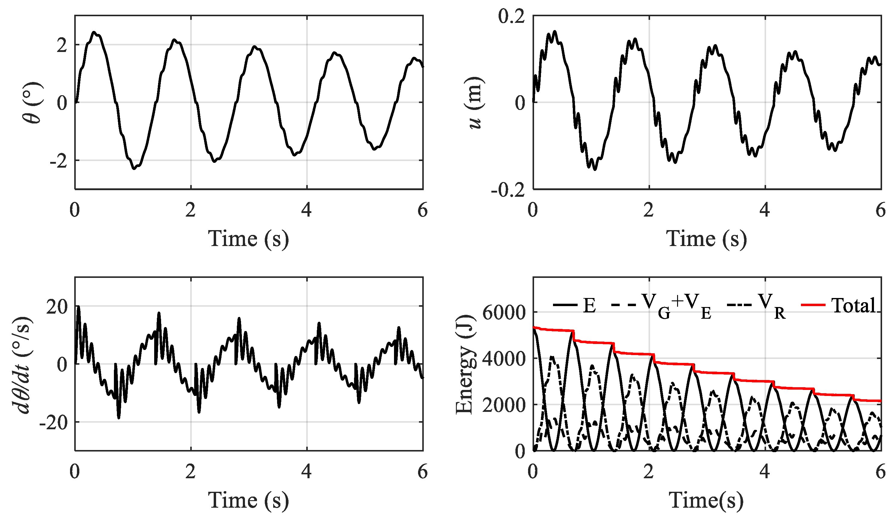
A case study of a pole structure with a height H of 10 m is given to illustrate the analysis. The uniformly distributed mass of the column along height is 500 kg/m, and no lump mass is added at the top. The bending stiffness of the pole is 3.5 × 10⁷ N.m2. When the base is fixed, the first-order frequency and the damping ratio are 1.5 Hz and 0.025, respectively. A base isolation design with a rocking pad width of 300 mm, as shown in Figure 2, is adopted in this structure. A total of 10 elastic restrainer are arranged circularly with a diameter of 750 mm, and the stiffness of each restrainer is 5 kN/mm. The initial condition of the structure is zero rotation, zero translational deformation, and zero angular velocity, while the initial translational velocity is 3 m/s. The structure enters a state of free rocking attenuation. Figure 7 shows the numerical analysis results based on the model in this section, including rotation angle, angular velocity, translational deformation, and the energy of the system. It can be seen that the system has a relatively short residence time in the 1DOF state. This is because a small amount of deformation (ucr = 5 mm) can cause the structure to enter a rocking state. The deformation of the structure is accompanied by high-frequency vibrations while maintaining the same pace as the rocking motion. This high-frequency part is the manifestation of the first-order deformation mode of the structure with a shifted frequency due to changes in supporting conditions after uplifting [48,58].
The energy curve represents the exchange of potential energy and kinetic energy, as well as the energy dissipation during the response. In this case study, the system exhibits initial velocity and experiences no base excitation. Therefore, monitoring changes in system energy provides insights into the damping characteristics of the system. As illustrated in Figure 7, the total energy dissipation of the system originates from two primary sources. Firstly, structural damping manifests as a gradual decrease in system energy, aligning with the inherent damping of the pole-type structure. Secondly, abrupt energy decreases signify dissipation due to rocking collisions, contributing to the system damping as the second source. If rocking restrainers with energy dissipation properties are utilized, their hysteresis energy dissipation constitutes the third source of system damping.
The structural damping of the pole-type structure can be quantified when it is with a fixed base. However, energy dissipation from rocking collisions and the hysteretic energy dissipation from restrainers depend on the vibration amplitude and cannot be accurately represented by a fixed equivalent damping coefficient. The influences of rocking impact and hysteretic behaviour of restrainers have been factored into the analytical model.
4. Experimental Study
4.1. Testing Specimen, Setup and Schedule
The effectiveness of the restrained rocking isolation design for pole-type structures is validated by the experimental study in this section. Additionally, verifying the accuracy of the analytical model proposed in this paper is of equal significance. The shaking table test conducted in this section utilized a full-scale prototype as the specimen; therefore, the results obtained carry greater practical significance.
The specimen involved surge arrester equipment used in an Ultra High Voltage (UHV) electric power substation, as shown in Figure 8. The surge arrester comprised six porcelain insulators, with the upper five insulators being 2.12 m in height and 1350 kg in weight. The lower insulator was 0.65 m in height and 400 kg in weight, making the total weight of the pole-type structure 7150 kg. The main structural component of the insulator was a porcelain hollow core bushing with an outer diameter of 510 mm and an inner diameter of 400 mm. The elastic modulus of the porcelain material was 1.1 × 10¹¹ N/m2. The fundamental frequency of this pole-type structure was around 1.5 Hz, while the structural damping of the fixed based specimen was around 2%.
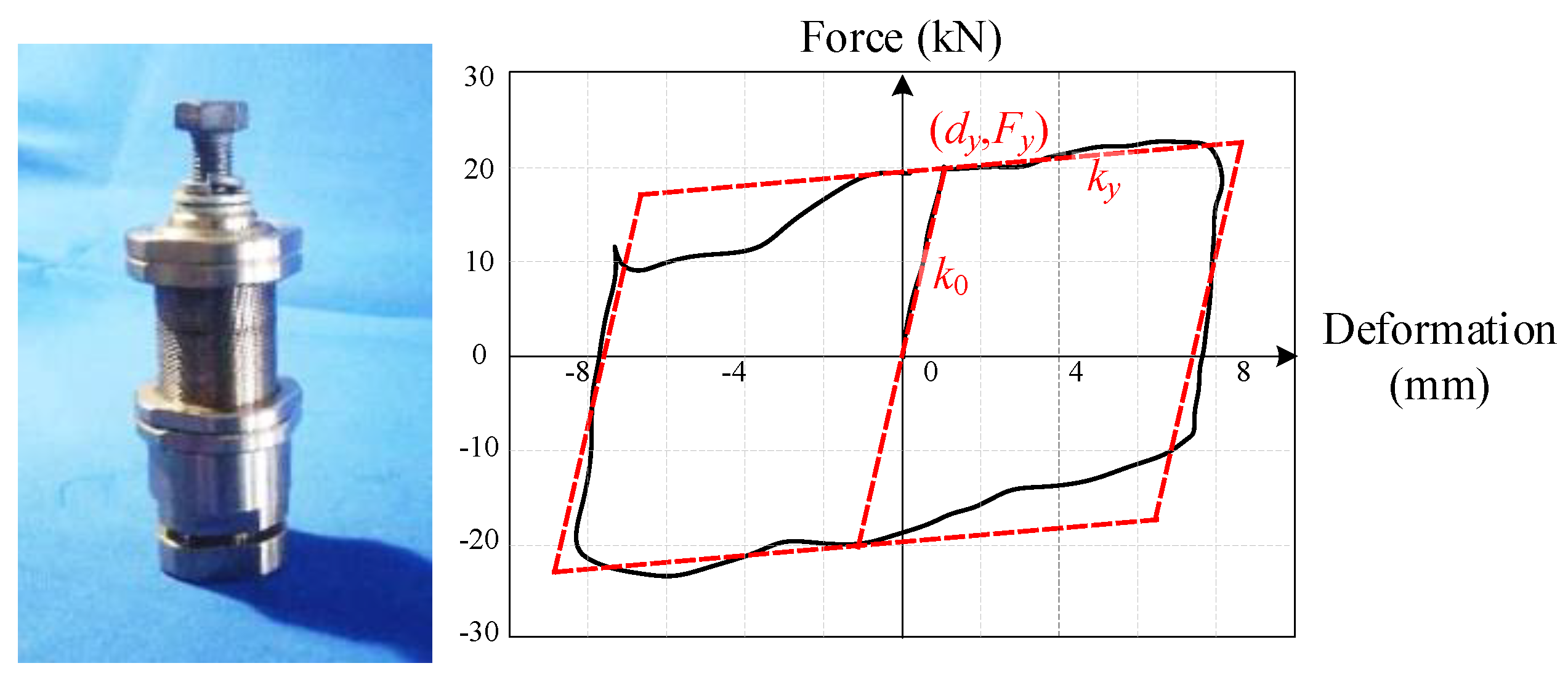
In the rocking isolation design, the width of the rocking pad was 375 mm. Ten restrainers were installed at the bottom of the pole-type structure, evenly distributed in a circle with a diameter of 770 mm. The restrainers exhibited typical metallic yielding hysteretic behaviour, as depicted in Figure 9. This device features an internally filled lead alloy core, which has typical metallic yielding behaviour under axial loading. Subject to shear forces, the core undergoes repetitive yielding of lead alloy. The recrystallization properties inherent in lead alloy ensure the stability of the mechanical performance of the core throughout the repeated shear-yielding cycles. The yielding load of the damper was 40 kN, the stiffness before yielding was 60 kN/mm, and the stiffness after yielding was 1% of the initial stiffness.
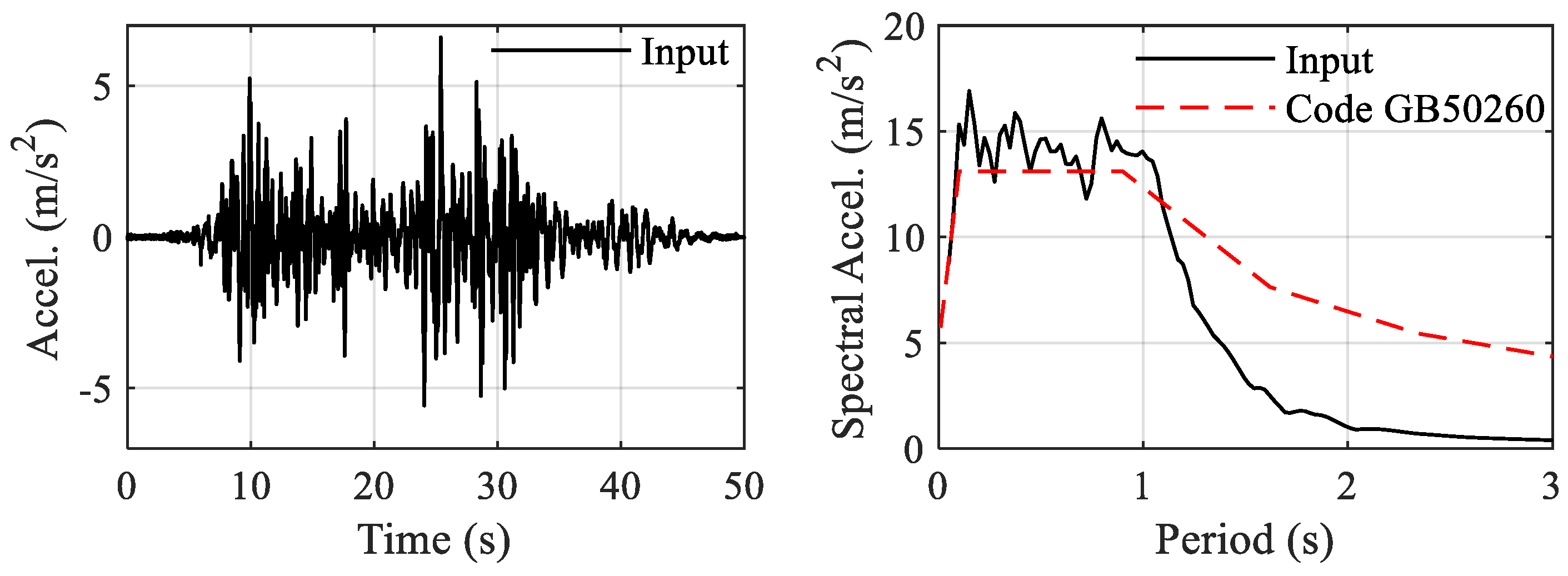
The setup of the shaking table test is shown in Figure 8, and the test was carried out according to the schedule outlined in Table 1. Test cases #1 to #5 were conducted on the fixed-base structure, whereas test cases #6 to #9 represented the rocking isolation condition. Due to the full-scale equipment specimen needing to be used in subsequent electrical performance tests following the seismic test, the input motion was chosen in accordance with the GB50260 standard [59], in which code-compatible artificial motion was employed. The time history of the artificial motion is depicted in Figure 10, exhibiting an acceleration response spectrum consistent with the code spectrum in the resonant segment.
4.2. Testing Results
Comparisons were made between the seismic response results of the specimen in the conditions of rocking isolation and a fixed-base. In the comparison of acceleration response between test case #4 and #6, shown in Figure 11, it can be seen that the acceleration at the top decreased from 1 g to 0.45 g under the input with PGA of 1.4 × 0.2 g. At the same time, the Frequency Response Function (FRF) on the right shows that the predominant frequency of the equipment decreased from 1.4 Hz to an unfixed frequency of around 0.5–0.8 Hz. This was a result from the rocking motion in which the frequency was not fixed but related to the amplitude. The strain response indicated the seismic internal force at the porcelain component. In the fixed-base test shown in Figure 12, the strain at the base was about 195 με and the corresponding stress was 21.5 MPa, which was around 60% of the allowable stress of the porcelain material. In the rocking isolation test case, this value was lowered to 95 με or 10.4 MPa, with a decreasing rate of 55%. After the test, the specimen returned to an upright position without any residual tilting.
Similar experimental results were further observed in the test case of 1.4 × 0.4 g. Figure 13 shows a comparison of the acceleration at the top and the bending moment at the base (derived from strain). The results of the rocking isolation were recorded in test case #8, while the fixed-base case results were obtained from numerical analysis of a calibrated non-isolation model. It is evident that, by employing the restrained rocking design, the bending moment was reduced from 485 kN·m to 202 kN·m, achieving a reduction rate of 58%. Importantly, there was no residual tilting observed after the earthquake, indicating the effectiveness of the self-centering capability of the rock mechanism.
4.3. Validation of the Restrained Rocking Model
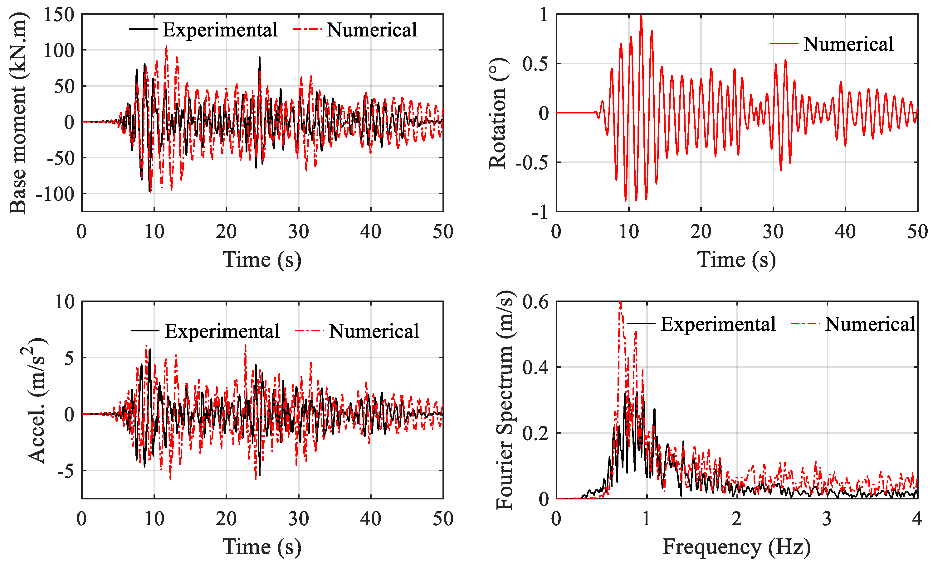
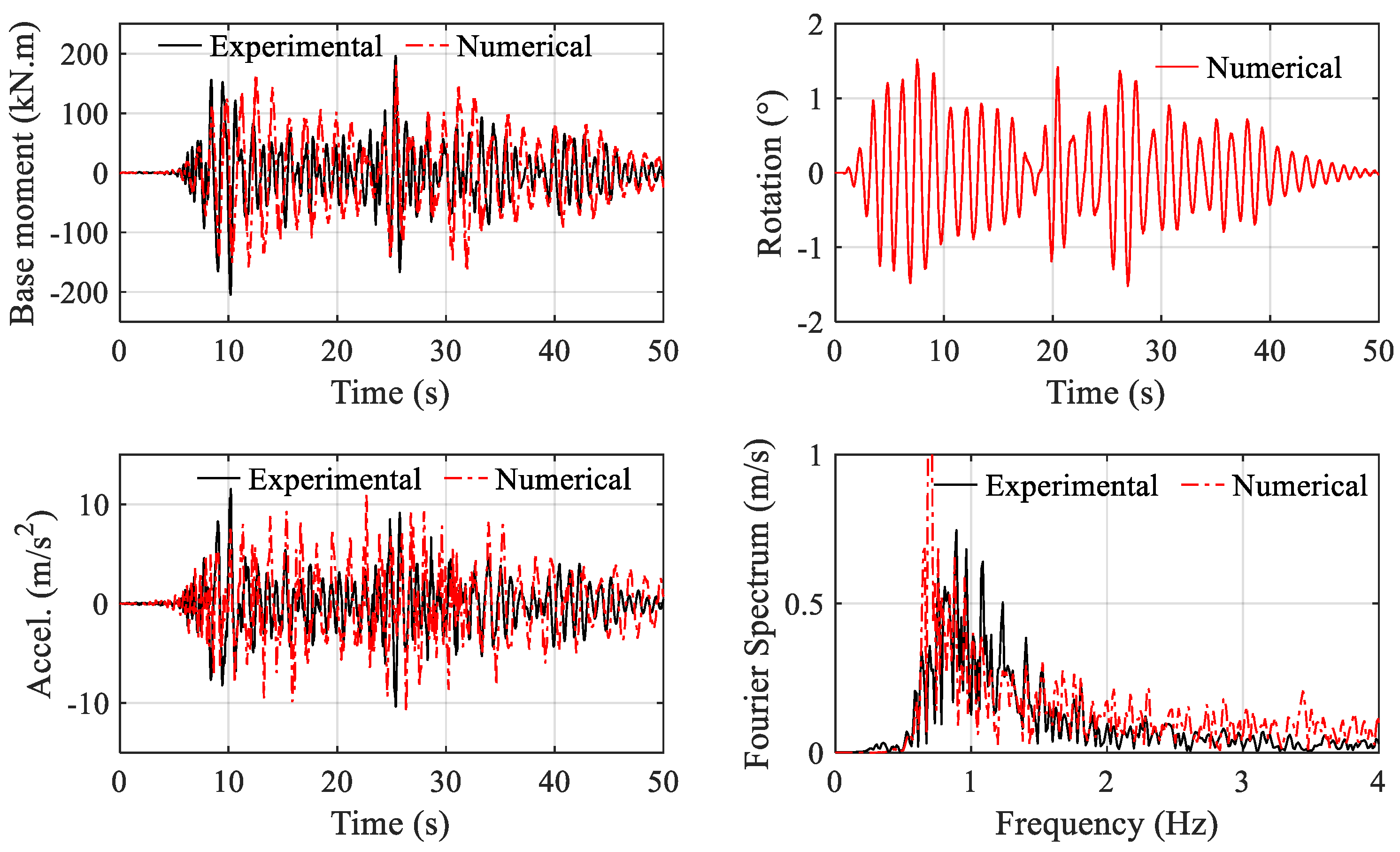
Table 2 presents a summary of the parameters utilized in the seismic response analysis, based on the analytical model developed in Section 3. Figure 14 and Figure 15 illustrate the comparison between experimental results and analysis results for test case #6 and test case #8, respectively. The differences between the predicted values and experimental values of amplitudes of bending moment and acceleration were less than 12%, validating the effectiveness of the analytical model in Section 3. The rotational behaviour depicted in the figures indicates that the structure underwent a continuous rocking motion throughout the process, thereby cutting down the bending moment at the base. Moreover, the rotation remained below two degrees in the 1.4 × 0.4 g test case, underscoring the effectiveness of the rocking restrainers.
5. Discussion on the Intensity Measure Governing the Response
This section uses the validated model to study the characteristics of the responses of pole-type structures under different seismic excitations. A total number of 21 earthquake records with magnitudes of 6.5 or above, as well as PGAs ranging from 0.1 g to 0.8 g, were selected from the PEER strong ground motion database [60]. The structural model with a restrained rocking design, as described in Table 2, was adopted in the numerical study. The analysis results were visualized in Figure 16 and Figure 17, including the Intensity Measures (IM) of the input motion and the response of the structure.
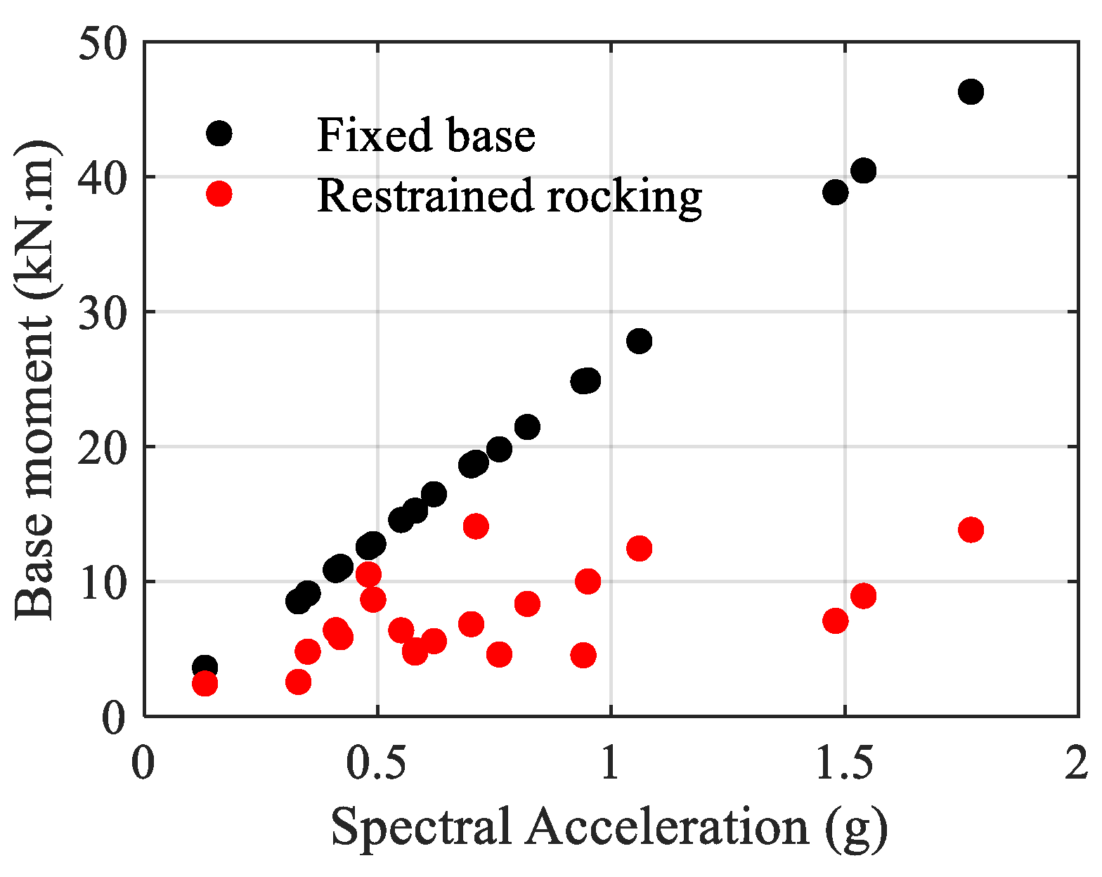
Figure 16 compares the base moment of the two structures, with the horizontal axis representing the spectral acceleration at the fundamental period. It is evident that the restrained rocking design achieved an average of 57% reduction in seismic internal forces (ranging from 16% to 82%). Additionally, there is a trend indicating that, the greater the seismic internal force in the fixed base structure, the more significant the isolation effect. For the fixed base structure, the seismic demand is primarily controlled by spectral acceleration. However, no significant correlation is observed between spectral acceleration and base moment for restrained rocking structures.
This study also investigated the seismic demand on pole-type structures with restrained rocking, considering intensity measures (IM) such as peak ground acceleration (PGA), peak ground velocity (PGV), peak ground displacement (PGD), peak spectral acceleration demand (PAD), peak spectral velocity demand (PVD), and peak spectral displacement demand (PDD). The regression analysis results are shown in Figure 17. The PGA and PAD exhibit the lowest correlation with the seismic responses, whereas the PGV and PDD demonstrate the strongest correlation.
A seismic demand model taking base moment M as the Engineering Demand Parameter (EDP) can be expressed as:
In this example, the values for a and b are −0.36 and 0.73, respectively; and the values for c and d are 0.46 and 0.67, respectively. This observation aligns with findings from other types of rocking structures [61,62,63], indicating a sensitivity to major velocity pulses. Consequently, this result underscores the importance of considering the velocity spectrum characteristics of the construction site when defining input motion in the design of pole-type structures with restrained rocking.
6. Conclusions
The traditional seismic isolation designs for pole-type structures typically involve engineering the base of the structure into a rotational hinge with restraints. However, this approach lacks a re-centring capability in the event of failure or yielding of the restrainer, thereby posing a risk of tilting and functionality failure following earthquakes. To address this challenge, a novel isolation design incorporating a restrained rocking mechanism at the base of the structure was proposed. The main outcomes of the paper are outlined below:
(1) The proposed design features a width-adjustable rocking interface at the base of the pole-type structure, surrounded by circularly arranged rocking restrainers. This configuration disrupts the transmission path of earthquake energy while introducing a dual mechanism for re-centring, restoring moments by gravitational force and restraining force.
(2) Experimental studies were conducted on full-scale porcelain surge arresters in high-voltage substations. The results demonstrated a reduction in internal force by more than 50%, with rotation controlled within two degrees under both 0.2 g and 0.4 g level excitation. Importantly, the specimen could return to an upright position after the test.
(3) The analytical model for the pole-type structures with restrained rocking isolation was developed and validated in this study. The establishment of analytical models provides an effective tool for the parameter design of the isolation system.
(4) This study explored the seismic demand model for the pole-type structure with the restrained rocking design. It was found that the structure’s response exhibited a minor correlation with spectral acceleration but was sensitive to peak ground velocity and peak displacement demand. This finding underscores the importance of considering the velocity spectrum when selecting input motions in seismic design.
Author Contributions
Conceptualization, S.L. and Z.L.; methodology S.L., Y.H. and B.S.; validation, S.L.; formal analysis S.L., Y.H., B.S. and G.H.; writing—original draft, S.L.; writing—review and editing, Y.H., B.S. and G.H.; project administration, Z.L.; supervision, G.H.; funding acquisition, S.L. and Z.L. All authors have read and agreed to the published version of the manuscript.
Funding
This research was funded by the University of Science and Technology Beijing, project number: TZB20230101.
Data Availability Statement
Data are contained within the article.
Acknowledgments
The tests in the study were organized by the China Electric Power Research Institute.
Conflicts of Interest
The authors declare no conflicts of interest.
References
- Siringoringo, D.M.; Fujino, Y.; Nagasaki, A.; Matsubara, T. Seismic Performance Evaluation of Existing Light Poles on Elevated Highway Bridges. Struct. Infrastruct. Eng. 2021, 17, 649–663. [Google Scholar] [CrossRef]
- Baghmisheh, A.G.; Mahsuli, M. Seismic Performance and Fragility Analysis of Power Distribution Concrete Poles. Soil Dyn. Earthq. Eng. 2021, 150, 106909. [Google Scholar] [CrossRef]
- Ibrahim, A.M.; El Damatty, A.A.; El Ansary, A.M. Finite Element Modelling of Pre-Stressed Concrete Poles under Downbursts and Tornadoes. Eng. Struct. 2017, 153, 370–382. [Google Scholar] [CrossRef]
- Stephens, M.; Xu, Z.; Whittaker, C.; Wotherspoon, L. Vulnerability of Power Distribution Utility Poles to Tsunami Bore Impacts. J. Coast. Hydraul. Struct. 2023, 3. [Google Scholar] [CrossRef]
- Ju, Y.; Zhao, J.; Wang, D.; Song, Y. Experimental Study on Flexural Behaviour of Reinforced Reactive Powder Concrete Pole. Constr. Build. Mater. 2021, 312, 125399. [Google Scholar] [CrossRef]
- Sasaki, T.; Nozawa, S.; Tsukishima, D.; Kaneko, A. Earthquake Damage to Concrete Utility Poles for Shinkansen and Remedial Measure. Concr. J. 2015, 53, 622–628. [Google Scholar] [CrossRef]
- Li, S.; Tsang, H.-H.; Cheng, Y.; Lu, Z. Effects of Sheds and Cemented Joints on Seismic Modelling of Cylindrical Porcelain Electrical Equipment in Substations. Earthq. Struct. 2017, 12, 55–65. [Google Scholar] [CrossRef]
- Xue, Y.; Cheng, Y.; Zhu, Z.; Li, S.; Liu, Z.; Guo, H.; Zhang, S. Study on Seismic Performance of Porcelain Pillar Electrical Equipment Based on Nonlinear Dynamic Theory. Adv. Civ. Eng. 2021, 2021, 8816322. [Google Scholar] [CrossRef]
- Takhirov, S.; Schiff, A.; Kempner, L.; Fujisaki, E. Breaking Strength of Porcelain Insulator Sections Subjected to Cyclic Loading. In TCLEE 2009: Lifeline Earthquake Engineering in a Multihazard Environment; American Society of Civil Engineers: Reston, VA, USA, 2009; pp. 1–12. [Google Scholar]
- He, C.; Xie, Q.; Yang, Z.; Xue, S. Seismic Evaluation and Analysis of 1100-KVUHV Porcelain Transformer Bushings. Soil Dyn. Earthq. Eng. 2019, 123, 498–512. [Google Scholar] [CrossRef]
- Ma, G.L.; Xie, Q.; Whittaker, A.S. Physical and Numerical Simulations of the Seismic Response of a 1,100 KV Power Transformer Bushing. Earthq. Spectra 2018, 34, 1515–1541. [Google Scholar] [CrossRef]
- Li, S.; Tsang, H.-H.; Cheng, Y.; Lu, Z. Considering Seismic Interaction Effects in Designing Steel Supporting Structure for Surge Arrester. J. Constr. Steel Res. 2017, 132, 151–163. [Google Scholar] [CrossRef]
- Li, S.; Cheng, Y.; Lu, Z.; Lam, N.; Xue, Y.; Wang, H. Full-Scale Testing on Seismic Performance of Surge Arrester with Retrofitted Composite Insulators. Buildings 2022, 12, 1720. [Google Scholar] [CrossRef]
- Epackachi, S.; Dolatshahi, K.M.; Oliveto, N.D.; Reinhorn, A.M. Mechanical Behavior of Electrical Hollow Composite Post Insulators: Experimental and Analytical Study. Eng. Struct. 2015, 93, 129–141. [Google Scholar] [CrossRef]
- Moustafa, M.A.; Mosalam, K.M. Structural Performance of Porcelain and Polymer Post Insulators in High Voltage Electrical Switches. J. Perform. Constr. Facil. 2016, 30, 04016002. [Google Scholar] [CrossRef]
- Yu, Y.; Li, G.; Li, P.; Zhu, Q. Investigation and Analysis of Electric Equipment Damage in Sichuan Power Grid Caused by Wenchuan Earthquake. Power Syst. Technol. 2008, 32, T1. [Google Scholar]
- Wang, Z. A Preliminary Report on the Great Wenchuan Earthquake. Earthq. Eng. Eng. Vib. 2008, 7, 225–234. [Google Scholar] [CrossRef]
- Kwasinski, A.; Eidinger, J.; Tang, A.; Tudo-Bornarel, C. Performance of Electric Power Systems in the 2010-2011 Christchurch, New Zealand, Earthquake Sequence. Earthq. Spectra 2014, 30, 205–230. [Google Scholar] [CrossRef]
- Mimura, N.; Yasuhara, K.; Kawagoe, S.; Yokoki, H.; Kazama, S. Damage from the Great East Japan Earthquake and Tsunami—A Quick Report. Mitig. Adapt. Strateg. Glob. Chang. 2011, 16, 803–818. [Google Scholar] [CrossRef]
- Adachi, T.; Ellingwood, B.R. Serviceability of Earthquake-Damaged Water Systems: Effects of Electrical Power Availability and Power Backup Systems on System Vulnerability. Reliab. Eng. Syst. Saf. 2008, 93, 78–88. [Google Scholar] [CrossRef]
- Salman, A.M.; Li, Y. A Probabilistic Framework for Seismic Risk Assessment of Electric Power Systems. Procedia Eng. 2017, 199, 1187–1192. [Google Scholar] [CrossRef]
- Ang, H.S.; Pires, J.A.; Villaverde, R. A Model for the Seismic Reliability Assessment of Electric Power Transmission Systems. Reliab. Eng. Syst. Saf. 1996, 51, 7–22. [Google Scholar] [CrossRef]
- Cheng, K.; Wang, Y.; Fang, H.; Qian, C.; Wu, P. Experimental Investigation and Prediction for Bending Creep of Glass Fiber-Reinforced Polymer Pultruded Tube. Buildings 2023, 13, 2714. [Google Scholar] [CrossRef]
- Li, S.; Tsang, H.-H.; Cheng, Y.; Lu, Z. Seismic Testing and Modeling of Cylindrical Electrical Equipment with GFRP Composite Insulators. Compos. Struct. 2018, 194, 454–467. [Google Scholar] [CrossRef]
- Xiao, J. Achievement of Electrical Technology in Sichuan Wenchuan Earthquake. Electr. Age 2008, 12, 32–34. [Google Scholar]
- Gökçe, T.; Yüksel, E.; Orakdöğen, E. Seismic Performance Enhancement of High-Voltage Post Insulators by a Polyurethane Spring Isolation Device. Bull. Earthq. Eng. 2019, 17, 1739–1762. [Google Scholar] [CrossRef]
- Xie, Q.; Shi, G.; Liu, Y. Influence of Lumped Mass and Rotary Inertia on Seismic Isolated Post Equipment. J. Constr. Steel Res. 2022, 199, 107604. [Google Scholar] [CrossRef]
- Cheng, Y.; Li, S.; Lu, Z.; Liu, Z.; Zhu, Z. Seismic Risk Mitigation of Cylindrical Electrical Equipment with a Novel Isolation Device. Soil Dyn. Earthq. Eng. 2018, 111, 41–52. [Google Scholar] [CrossRef]
- Liu, Z.; Zhang, L.; Cheng, Y.; Lu, Z.; Zhu, Z. Seismic Performance Improvement Using Bolt-on Isolators on Interconnected Slender Electrical Equipment. Eng. Struct. 2023, 289, 116238. [Google Scholar] [CrossRef]
- Yang, Z.; Xie, Q.; He, C.; Xue, S. Numerical Investigation of the Seismic Response of a UHV Composite Bypass Switch Retrofitted with Wire Rope Isolators. Earthq. Eng. Eng. Vib. 2021, 20, 275–290. [Google Scholar] [CrossRef]
- Alessandri, S.; Giannini, R.; Paolacci, F.; Malena, M. Seismic Retrofitting of an HV Circuit Breaker Using Base Isolation with Wire Ropes. Part 1: Preliminary Tests and Analyses. Eng. Struct. 2015, 98, 251–262. [Google Scholar] [CrossRef]
- Alessandri, S.; Giannini, R.; Paolacci, F.; Amoretti, M.; Freddo, A. Seismic Retrofitting of an HV Circuit Breaker Using Base Isolation with Wire Ropes. Part 2: Shaking-Table Test Validation. Eng. Struct. 2015, 98, 263–274. [Google Scholar] [CrossRef]
- Housner, G.W. The Behavior of Inverted Pendulum Structures during Earthquakes. Bull. Seismol. Soc. Am. 1963, 53, 403–417. [Google Scholar] [CrossRef]
- Kavvadias, I.E.; Vasiliadis, L.K.; Elenas, A. Seismic Response Parametric Study of Ancient Rocking Columns. Int. J. Archit. Herit. 2017, 11, 791–804. [Google Scholar] [CrossRef]
- Papadopoulos, K.; Vintzileou, E.; Psycharis, I.N. Finite Element Analysis of the Seismic Response of Ancient Columns. Earthq. Eng. Struct. Dyn. 2019, 48, 1432–1450. [Google Scholar] [CrossRef]
- Grigorian, M.; Grigorian, C. An Introduction to the Structural Design of Rocking Wall-Frames with a View to Collapse Prevention, Self-Alignment and Repairability. Struct. Des. Tall Spec. Build. 2016, 25, 93–111. [Google Scholar] [CrossRef]
- Casapulla, C.; Giresini, L.; Lourenço, P.B. Rocking and Kinematic Approaches for Rigid Block Analysis of Masonry Walls: State of the Art and Recent Developments. Buildings 2017, 7, 69. [Google Scholar] [CrossRef]
- Aghagholizadeh, M.; Makris, N. Response Analysis of Yielding Structures Coupled to Rocking Walls with Supplemental Damping. Earthq. Eng. Struct. Dyn. 2021, 50, 2672–2689. [Google Scholar] [CrossRef]
- Xiang, M.; Xiong, F.; Lu, Y.; Ge, Q.; Yan, H.; Ran, M. Structural Displacement Ratios for Seismic Evaluation of Structures on Rocking Shallow Foundations. Buildings 2022, 12, 174. [Google Scholar] [CrossRef]
- Giouvanidis, A.I.; Dong, Y. Seismic Loss and Resilience Assessment of Single-Column Rocking Bridges. Bull. Earthq. Eng. 2020, 18, 4481–4513. [Google Scholar] [CrossRef]
- Piras, S.; Palermo, A.; Saiid Saiidi, M. State-of-the-Art of Posttensioned Rocking Bridge Substructure Systems. J. Bridge Eng. 2022, 27, 03122001. [Google Scholar] [CrossRef]
- Pollino, M.; Bruneau, M. Dynamic Seismic Response of Controlled Rocking Bridge Steel-Truss Piers. Eng. Struct. 2008, 30, 1667–1676. [Google Scholar] [CrossRef]
- Agalianos, A.; Psychari, A.; Vassiliou, M.F.; Stojadinovic, B.; Anastasopoulos, I. Comparative Assessment of Two Rocking Isolation Techniques for a Motorway Overpass Bridge. Front. Built Environ. 2017, 3, 47. [Google Scholar] [CrossRef]
- Thiers-Moggia, R.; Málaga-Chuquitaype, C. Seismic Protection of Rocking Structures with Inerters. Earthq. Eng. Struct. Dyn. 2019, 48, 528–547. [Google Scholar] [CrossRef]
- Li, S.; Tsang, H.-H.; Lam, N. Seismic Protection by Rocking with Superelastic Tendon Restraint. Earthq. Eng. Struct. Dyn. 2022, 51, 1718–1737. [Google Scholar] [CrossRef]
- Dimitrakopoulos, I.; Dejong, M. Seismic Overturning of Damped Rocking Structures. 2011. Available online: https://repository.hkust.edu.hk/ir/Record/1783.1-52590 (accessed on 15 January 2023).
- Pan, X.; Málaga-Chuquitaype, C. Seismic Control of Rocking Structures via External Resonators. Earthq. Eng. Struct. Dyn. 2020, 49, 1180–1196. [Google Scholar] [CrossRef]
- Acikgoz, S.; Ma, Q.; Palermo, A.; DeJong, M.J. Experimental Identification of the Dynamic Characteristics of a Flexible Rocking Structure. J. Earthq. Eng. 2016, 20, 1199–1221. [Google Scholar] [CrossRef]
- Acikgoz, S.; Dejong, M.J. The Interaction of Elasticity and Rocking in Flexible Structures Allowed to Uplift. Earthq. Eng. Struct. Dyn. 2012, 41, 2177–2194. [Google Scholar] [CrossRef]
- Vassiliou, M.F.; Mackie, K.R.; Stojadinović, B. Dynamic Response Analysis of Solitary Flexible Rocking Bodies: Modeling and Behavior under Pulse-like Ground Excitation. Earthq. Eng. Struct. Dyn. 2014, 43, 1463–1481. [Google Scholar] [CrossRef]
- Reggiani Manzo, N.; Vassiliou, M.F. Displacement-Based Analysis and Design of Rocking Structures. Earthq. Eng. Struct. Dyn. 2019, 48, 1613–1629. [Google Scholar] [CrossRef]
- Vassiliou, M.F.; Truniger, R.; Stojadinović, B. An Analytical Model of a Deformable Cantilever Structure Rocking on a Rigid Surface: Development and Verification. Earthq. Eng. Struct. Dyn. 2015, 44, 2775–2794. [Google Scholar] [CrossRef]
- Chopra, A.K. Dynamics of Structures-Theory and Applications to Earthquake Engineering, 4th ed.; Prentice Hall: Hoboken, NJ, USA, 2004. [Google Scholar]
- Martelli, A.; Forni, M. Seismic Isolation and Other Anti-Seismic Systems Recent Applications in Italy and Worldwide. J. Anti-Seism. Syst. Int. Soc. 2010, 1, 75–123. [Google Scholar]
- D’Amato, M.; Gigliotti, R.; Laguardia, R. Seismic Isolation for Protecting Historical Buildings: A Case Study. Front. Built Environ. 2019, 5, 87. [Google Scholar] [CrossRef]
- Li, S.; Tsang, H.-H.; Lam, N. Seismic Internal Force in Rocking Shear Frame with Superelastic Tendon Restraint. Earthq. Eng. Struct. Dyn. 2023, 52, 2272–2293. [Google Scholar] [CrossRef]
- Morin, D.J. Introduction to Classical Mechanics: With Problems and Solutions; Cambridge University Press: Cambridge, UK, 2008; ISBN 9780521876223. [Google Scholar]
- Acikgoz, S.; DeJong, M.J. Analytical Modelling of Multi-Mass Flexible Rocking Structures. Earthq. Eng. Struct. Dyn. 2016, 45, 2103–2122. [Google Scholar] [CrossRef]
- GB 50260-2013; Code for Seismic Design of Electrical Installations. Ministry of Housing and Urban-Rural Development: Beijing, China, 2013.
- PEER Pacific Earthquake Engineering Research Center. Available online: http://peer.berkeley.edu/products/strong_ground_motion_db.html (accessed on 28 January 2021).
- Lachanas, C.G.; Vamvatsikos, D.; Dimitrakopoulos, E.G. Intensity Measures as Interfacing Variables versus Response Proxies: The Case of Rigid Rocking Blocks. Earthq. Eng. Struct. Dyn. 2023, 52, 1722–1739. [Google Scholar] [CrossRef]
- Bantilas, K.E.; Kavvadias, I.E.; Tyrtaiou, M.; Elenas, A. Hilbert–Huang-Transform-Based Seismic Intensity Measures for Rocking Response Assessment. Appl. Sci. 2023, 13, 1634. [Google Scholar] [CrossRef]
- Bantilas, K.E.; Kavvadias, I.E.; Vasiliadis, L.K.; Elenas, A. Seismic Fragility and Intensity Measure Investigation for Rocking Podium Structures under Synthetic Pulse-like Excitations. Earthq. Eng. Struct. Dyn. 2021, 50, 3441–3459. [Google Scholar] [CrossRef]
Figure 2.
Proposed design of restrained rocking isolation of pole-type cylindrical electrical equipment.
Figure 2.
Proposed design of restrained rocking isolation of pole-type cylindrical electrical equipment.

Figure 3.
Rocking motion at the isolation device.

Figure 4.
Mechanical behaviours of rocking restrainers.

Figure 5.
Dynamics modeling of the pole-type structure with restrained rocking isolation.

Figure 6.
Sequence of rocking.

Figure 7.
Energy of the system in rocking vibration.

Figure 8.
Test specimen of surge arrester equipment used in a Ultra High Voltage (UHV) electric power substation.
Figure 8.
Test specimen of surge arrester equipment used in a Ultra High Voltage (UHV) electric power substation.

Figure 9.
Rocking restrainer adopted in the experimental study.

Figure 10.
Input motion.

Figure 11.
Acceleration responses in test case #4 and #6.

Figure 12.
Strain responses in test case #4 and #6.

Figure 13.
Acceleration and bending moment in test case #8.

Figure 14.
Comparison between experiment results and analysis results in test case #6.

Figure 15.
Comparison between experiment results and analysis results in test case #8.

Figure 16.
A comparison of base moment demand of the pole-type structure with and without rocking isolation under various input excitations.
Figure 16.
A comparison of base moment demand of the pole-type structure with and without rocking isolation under various input excitations.

Figure 17.
Relationship between intensity measures of input motion and base moment response (kN.m) of the restrained rocking pole-type structure. The units for PGA, PGV, PGD, PAD, PVD, and PDD are g, cm/s, cm, g, m/s, and m, respectively.
Figure 17.
Relationship between intensity measures of input motion and base moment response (kN.m) of the restrained rocking pole-type structure. The units for PGA, PGV, PGD, PAD, PVD, and PDD are g, cm/s, cm, g, m/s, and m, respectively.


Table 1.
Test schedule.
| No. | Setup | Input Motion | PGA | Direction |
|---|---|---|---|---|
| 1 | Fixed base | White noise | 0.05 g | X direction |
| 2 | Code compatible wave | * 1.4 × 0.15 g | ||
| 3 | White noise | 0.05 g | ||
| 4 | Code compatible wave | 1.4 × 0.20 g | ||
| 5 | White noise | 0.05 g | ||
| 6 | Restrained rocking | Code compatible wave | 1.4 × 0.20 g | |
| 7 | White noise | 0.05 g | ||
| 8 | Code compatible wave | 1.4 × 0.40 g | ||
| 9 | White noise | 0.05 g |
* The input motion was scaled by 1.4 times for considering the amplification effect of supporting podium or frame [12].
Table 2.
Parameters of testing specimen.
| Pole-type structure | |||||
| Height | 11.2 m | Diameter (outside) | 510 mm | Diameter (inside) | 400 mm |
| Distributive mass | 632 kg/m | Added mass at top | 50 kg | Elastic modulus of porcelain | 110 GPa |
| Allowable stress of porcelain | 36 MPa | Natural Frequency | 1.6 Hz | Equivalent sect. stiffness | 8.5 × 10⁷ N.m2 |
| Damping | 3.5% | ||||
| Design of rocking isolation at base | |||||
| Width of rocking base | 375 mm | Number of restrainers | 10 | Arrangement circle diameter | 770 mm |
| Yielding force of restrainer | 40 kN | Initial stiffness of restrainer | 60 kN/mm | Post yielding stiffness | 0.6 kN/mm |
Disclaimer/Publisher’s Note: The statements, opinions and data contained in all publications are solely those of the individual author(s) and contributor(s) and not of MDPI and/or the editor(s). MDPI and/or the editor(s) disclaim responsibility for any injury to people or property resulting from any ideas, methods, instructions or products referred to in the content. |
© 2024 by the authors. Licensee MDPI, Basel, Switzerland. This article is an open access article distributed under the terms and conditions of the Creative Commons Attribution (CC BY) license (https://creativecommons.org/licenses/by/4.0/).
Share and Cite
MDPI and ACS Style
Li, S.; Hu, Y.; Lu, Z.; Song, B.; Huang, G. Seismic Isolation of Fragile Pole-Type Structures by Rocking with Base Restraints. Buildings 2024, 14, 1176. https://doi.org/10.3390/buildings14041176
AMA Style
Li S, Hu Y, Lu Z, Song B, Huang G. Seismic Isolation of Fragile Pole-Type Structures by Rocking with Base Restraints. Buildings. 2024; 14(4):1176. https://doi.org/10.3390/buildings14041176
Chicago/Turabian StyleLi, Sheng, Yao Hu, Zhicheng Lu, Bo Song, and Guozhong Huang. 2024. "Seismic Isolation of Fragile Pole-Type Structures by Rocking with Base Restraints" Buildings 14, no. 4: 1176. https://doi.org/10.3390/buildings14041176
Note that from the first issue of 2016, this journal uses article numbers instead of page numbers. See further details here.