
Numerical Study of the Solar Energy-Powered Embedded Pipe Envelope System

1
Department of Civil Engineering, Faculty of Engineering, Universiti Malaya, Lembah Pantai, Kuala Lumpur 50603, Malaysia
2
School of Civil Engineering, Sichuan University of Science and Engineering, Zigong 643000, China
3
Department of Mechanical Engineering, Faculty of Engineering, Universiti Malaya, Lembah Pantai, Kuala Lumpur 50603, Malaysia
4
Yunnan Key Laboratory of Disaster Reduction in Civil Engineering, Faculty of Civil Engineering and Mechanics, Kunming University of Science and Technology, Kunming 650500, China
5
School of Civil Engineering, Chongqing University, Chongqing 400045, China
*
Author to whom correspondence should be addressed.
Buildings 2024, 14(3), 613; https://doi.org/10.3390/buildings14030613
Submission received: 12 January 2024
/
Revised: 9 February 2024
/
Accepted: 20 February 2024
/
Published: 26 February 2024
(This article belongs to the Special Issue Sustainable Building Technology and High-Performance Building Engineering)
Abstract
:This study introduces a Solar Energy-Powered Embedded Pipe Envelope System (SEPES) designed to enhance indoor thermal comfort and reduce heating loads during the heating season. To achieve this objective, a dynamic simulation model coupling a SEPES and building thermal environment was established under the TRNSYS environment. Based on the model, a case analysis was conducted to investigate the operational characteristics of the system during the heating season in a rural building in Beijing. The results indicate that, on the coldest heating day, the system can elevate the indoor temperature by 14.5 °C, reducing the daily heat load from 76.3 kWh to 20.3 kWh, achieving a remarkable energy savings of 73.4%. Additionally, due to the utilization of lower solar heat collection temperatures, the energy efficiency of the system reaches 26.9%. Throughout the entire heating season, the SEPES system enhances the natural indoor temperature by 13.3 °C to 16.6 °C, demonstrating significant effectiveness. Moreover, regional adaptability analysis indicates that the SEPES achieves energy savings ranging from 43.9% to 66% during the heating season in cold regions and regions with hot summers and cold winters in China. Overall, the SEPES is most suitable for climates characterized by both low temperatures and abundant solar radiation in order to achieve optimal performance.
1. Introduction
Global attention has progressively shifted towards issues pertaining to energy and the environment in recent years. China has already adopted the objective of reaching the peak of its carbon dioxide emissions by the year 2030 and realizing carbon neutrality by the year 2060 as a part of its national strategy for sustainable development introduced in September 2022 [1]. Structures contribute substantially to overall energy consumption. The percentage of total energy consumption occupied by buildings reaches 36% and 40% in China and the United States, respectively [2,3,4]. This level of consumption causes 42% and 38% of emissions in China and the United States, respectively.
The predominant portion of energy utilized in buildings presently emanates from the combustion of fossil fuels. This approach not only significantly affects societal energy security but also engenders adverse environmental consequences [5,6,7,8]. In response, various research efforts have been undertaken to reduce non-renewable energy consumption in buildings, including improvements in HVAC equipment efficiency [9,10,11], optimization of the operational efficiency of building systems [12,13,14,15,16,17], and the paramount importance of increasing the incorporation of renewable and low-grade energy sources within building infrastructures [18,19,20]. Renewable energy typically exhibits low-grade and intermittent characteristics in the absence of grade-lifting or energy conversion processes (e.g., from heat to electricity). A fundamental concept in enhancing the exergy-effective utilization of renewable energy in buildings involves aligning building systems as closely as is feasible with these characteristics and circumventing the need for energy quality elevation, as typically required in conventional HVAC systems [21]. In pursuit of this objective, the building structure and configuration are integral components of the building system, exerting a substantial influence on the connection between the internal environment and the ambient surroundings. A more detailed analysis reveals that approximately half of the load is attributed to the heat gain and/or loss through the building envelope [22,23,24]. Addressing these challenges is paramount for mitigating energy and environmental issues, leading to numerous initiatives focused on improving building energy efficiency.
The pipe-embedded building envelope represents an innovative structural design wherein pipes are integrated, leveraging the flow of hot or cool mediums within them to mitigate heat or cold loss through the building envelope [12,13]. Pipe-embedded building envelopes coupled with cooling/heating source systems have gained increasing attention in recent years as a way to improve the energy efficiency and thermal comfort of buildings. Pipe-embedded building envelopes are also known as thermally active building system (TABS) [14,25], concrete core slab, active tuning building wall [15], etc. These systems involve the integration of pipes into the building envelope, typically in the form of walls [18,19], floors [26,27], or ceilings [28,29,30], which are used to distribute a cooling or heating fluid to the interior space. Oravec [31] pursued a comparative study on the applicability of radiant floor, wall, and ceiling heating systems. The study reached a conclusion indicating that wall heating incorporating pipes attached to a thermally insulating core demonstrated the highest thermal output. This configuration was found to be easily controllable, well-suited for building retrofit applications, and economically viable, albeit with limited thermal storage capacity. Zhou and Li [32] investigated the thermal performance of a pipe-embedded wall. Approximately 13% heat gain in summer and 33% heat loss in winter can be reduced by the pipe-embedded wall. Kan Xu [33] evaluated the heating performance of pipe-embedded roof. The findings revealed that the heating demand can be fulfilled, barring instances of extreme weather conditions. By employing auxiliary heating to maintain the indoor temperature above 17 ℃, the total energy needed for heating a room with a pipe-embedded roof can be diminished by 54% in comparison to a room with a conventional roof.
To decrease the energy consumption of the building, technologies are used as cooling/heating sources for embedded-pipe building envelope, such as heat pumps [34,35], solar water heaters [2] and other low-grade energy utilization systems [32,34,36,37]. Chong Shen [35] studied air source heat pumps(ASHP) for generating low-temperature hot water for the pipe-embedded wall. The ASHP and embedded-pipe coupling system could reduce the energy consumption of the boiler and indoor fan. Meanwhile, the energy efficiency ratio (EER) of ASHP is high when coupled with an embedded pipe system (from 4.5 to 10 in the case in Beijing). Anbang Li [34] introduced a novel low-grade energy utilization system, namely a pipe-embedded wall integrated with a ground source heat exchanger, and examined its energy-saving potential across five representative climate regions in China. Moreover, Li [38] conducted a study on the dynamic thermal performance of a pipe-embedded building envelope utilizing evaporative cooling water during the cooling season. The investigation involved analyzing the performance of this innovative envelope in various orientations within three representative cities in China, utilizing cooling water generated from an evaporative cooling tower. The findings indicate the efficacy of cooling pipes in the three cities, particularly in Beijing, where the reduction in heat gain during the cooling season amounts to 17.4 kWh per square meter of wall.
As the Sun, with a surface temperature of 5800 K, serves as the primary source of heat for the Earth, solar collectors are widely employed to supplement heat for buildings. The intermittent and uncontrollable nature of solar radiation can be effectively integrated with a building structure possessing substantial thermal mass, such as the building envelope. Simultaneously, the heat transfer medium within the solar collector can circulate through embedded pipes for efficient heat exchange. Consequently, solar collectors can be successfully coupled with pipe-embedded envelopes, exhibiting high response times [39].
In Zhang’s research [40], the heat transfer performance of the pipe-embedded building envelope, when coupled with solar collectors, was found to be adjustable and controllable. The study delved into the heat transfer performance and energy-saving characteristics of the coupling system using meteorological data from Jinan. It was determined that, during a typical winter, the heat loss from the south external wall was reduced by 14.47%. Consequently, this type of wall could significantly enhance the indoor thermal environment. Mohamad Ibrahim [2] observed that, by transferring solar energy from the south side to the north facade through embedded water pipes, the annual heating load reductions for houses employing the pipe-embedded system ranged between 28% and 43% for new houses, and 15% and 20% for old houses, in a Mediterranean climate, compared to those without this system.
Regarding the aforementioned literature (shown in Table 1), the solar energy-powered embedded pipe envelope system (SEPES) could be an efficient system to reduce indoor heating load and improve thermal comfort. Compared to those systems coupled with HVAC, the SEPES exhibits more pronounced effectiveness in reducing the Urban Heat Island (UHI) effect. The SEPES also demonstrates a more stable heating capacity compared to other systems utilizing low-grade energy sources, such as the geothermal heat exchanger. Moreover, previous research concentrated more on the physical parameters and thermal performance of single pipe-embedded envelope or solar collectors. There is little research on the performance of the SEPES in different climate zones with different solar energy resources. Furthermore, in order to extend the effective running time of the system, existing research [41,42] commonly utilized phase change material walls to store the excess heat of solar energy during the day. Although phase change walls have some advantages in energy efficiency, they also have some drawbacks. Phase change walls are expensive, difficult to maintain, relatively heavy, and have poor climate adaptability. Therefore, a heat storage water tank was used to prolong the operational duration of the system in this study. This article’s objective is to reveal the energy-saving potential and thermal performance of the SEPES using a TRNSYS model. The investigated parameters include the area of the solar chimney, tank volume, circulation flow of the solar chimney and circulation flow of the embedded pipe. The thermal performance of Solar Energy-Powered Environmental Systems (SEPESs), encompassing assessments of ambient temperature conditions and energy consumption, was systematically evaluated. In addition, an analysis of the regional adaptability of the SEPES was conducted. The outcomes of this investigation are anticipated to contribute to a comprehensive comprehension of the practical applications of SEPESs.
2. System Description and Numerical Model
2.1. The Solar Energy-Powered Embedded Pipe Envelope System
The scheme of the solar energy-powered embedded pipe envelope system (SEPES) is shown in Figure 1. As shown, the system consists of a set of solar collectors, a water tank, and an embedded pipe in the exterior wall and the building.
The exterior walls are composed of a brick layer. In the exterior wall, the water pipes are embedded in the middle position in a serpentine shape. The area of the embedded pipe structure on walls with different orientations is equal to the area of the solid wall. The embedded pipe areas for the east, west, north, and south walls are 11.25 m2, 13.5 m2, 26.28 m2, and 11.46 m2, respectively. The water inside the pipeline transfers heat sequentially to the various exterior walls of the building. The water pump provides power for the flow of water throughout the entire system.
There are two parts to the water circulation in the heat storage water tank. One of the loops is in the pipe-embedded wall, as previously indicated. In an additional circuit within the solar thermal collector, the heat generated by the photothermal effect is stored in a water tank, subsequently supplying the thermal energy to the building’s envelope structure. The high-absorptance collector surface of the solar thermal collector, positioned atop the building, absorbs solar radiation to generate heat, thereby heating the circulating water in the system.
2.2. Model Setting
The SEPES simulation model was developed using the module available in TRNSYS, as shown in Figure 2. Components and their functions in the coupled simulation platform are shown in Table 2. Module type 73 was chosen to achieve the best functionality of the solar thermal collector. The Hottel–Whillier steady-state model is used for evaluating the thermal performance of the collector [43]. The fundamental parameters of the solar thermal collector are set forth in Table 3.
The solar energy-powered embedded pipe envelope system is more suitable for standalone buildings due to its structure. A typical rural building in Beijing in Northern China was chosen to be the study case in this research, shown in Figure 2 [44]. The thermal–physical characteristics of the building envelope structure are determined in accordance with the design specifications for China’s cold region [45]. Additionally, this is a typical rural building facing south. The personnel density within the building is designed at 0.05 person/. The windows of all the houses were double-glazed with solar absorptance and emissivity of 0.6 and 0.9, respectively. The layout of the typical building in this study is shown in Figure 3. The fundamental parameters of the SEPES are set forth in Table 1. Further information concerning the house is given in Table 4.
2.3. Evaluated Index
In order to comprehensively assess the performance of the system throughout the entire heating season, three evaluation indexes have been defined in this study: the total annual heating load, the overall system energy consumption, and the system performance coefficient.
- -
- Annual heating load
During the heating season, the hourly heating load required to achieve the set indoor temperature is denoted as . Consequently, the total heating load for the entire heating season, denoted as , can be obtained as:
where, n1 and n2, respectively, denote the start and end times of the heating season.
- -
- System energy consumption
The system energy consumption is generated by the distribution system, namely the SC and BP pumps, and can be calculated as:
where and are the hourly energy consumption of SC and BP, respectively. and are the control signals for pumps SC and BP, 1 when started and 0 when stopped.
- -
- Coefficient of performance
The coefficient of performance (COP) of the SEPES system is the ratio of its reduction in indoor heat load and energy consumption:
3. Results and Discussion
3.1. A Case Study for Rural Buildings in Beijing
Beijing experiences distinct periods throughout the year, demarcated into the heating season and the non-heating season. The heating season spans from November 15th each year to March 15th of the subsequent year. Figure 4 illustrates the annual outdoor temperatures and the natural indoor temperatures of a typical rural building in Beijing. As depicted, despite the mitigating effects of solar radiation and thermal mass within the building envelope, indoor temperature fluctuations are less pronounced than outdoor temperatures, and the average indoor temperature surpasses that of the outdoor environment. Nevertheless, throughout the entire heating season, the natural indoor temperature remains below 10 °C, and under extreme climatic conditions indoor temperatures may plummet below 0 °C. Consequently, during this period, the building manifests a pronounced demand for intensive heating.
3.1.1. Room Temperature
Figure 5 presents the room temperatures throughout the entire heating season following the activation of the solar embedded pipe temperature control system. As illustrated in the figure, the indoor temperature can be consistently maintained above 10 °C throughout the heating season, and on days with an average temperature exceeding 5 °C, the room temperature may surpass 20 °C. The average natural indoor temperature for the entire heating season experiences a notable increase from its initial value of 3.3 °C, rising by 13.3 °C to 16.6 °C, indicating a significant warming effect. This signifies the system’s capability to markedly enhance thermal comfort within the room during the winter. However, it is imperative to note that, during the coldest month, the indoor temperature remains persistently below 15 °C. Consequently, it can be inferred that the system is only capable of fully meeting heating demands under specific conditions, necessitating the supplementary use of heating devices.
3.1.2. Heating Energy Consumption
As previously elucidated, buildings equipped with the Solar Energy-Powered Embedded Pipe Envelope System (SEPES) still require supplementary heating devices. In elucidating the system’s energy-saving performance in heating, the study conducted a comparative analysis of the daily heating loads between the building equipped and not equipped with the SEPES. As illustrated in Figure 6, upon activating the SEPES, the daily average heat load decreased from the previous 76.3 kWh/D to 20.3 kWh/D. Overall, with the SEPES operational, the total heating load for the heating season decreased from the initial 9305 kWh to 2478 kWh, yielding an energy-saving rate of 73.4%, indicating a remarkably significant energy-saving effect. Moreover, excluding extreme weather conditions, the daily load reduction consistently exceeded 50%. Thus, it can be inferred that the SEPES not only exhibits a notable effect in reducing thermal loads but also has the capability to diminish the capacity requirements of the heating system, thereby saving on the initial investment in this aspect of the system.
In order to conduct a more detailed investigation into the operational characteristics of the system, the study selected the coldest day (January 15th, as indicated in Figure 6) and subjected the 24-h operational features of the system to further analysis. Figure 7a illustrates the variations in outdoor and indoor temperatures throughout the day. The outdoor temperature ranged from a minimum of −13.5 °C to a maximum of −2.75 °C. In the case without the SEPES, the indoor natural temperature, while higher than the outdoor temperature, consistently remained below 0 °C. In contrast, in the case with the SEPES, the indoor temperature was maintained above 10 °C throughout the day, representing an elevation of approximately 14.5 °C compared to the control rooms. Additionally, due to fluctuations in the circulating water temperature, the room with the SEPES exhibited a slightly greater amplitude of temperature variation over the course of the day compared to the control room.
As a radiant temperature control system, the increase in room temperature stems from the improvement of the internal surface temperature of the wall. Figure 7b presents a comparative analysis of the internal surface temperatures of walls facing in different orientations in two cases. Unlike conventional structures, rooms equipped with an SEPES exhibit nearly identical internal surface temperatures on walls facing in different orientations due to the uniform inlet water temperature of embedded pipes on different wall surfaces. Besides, the SEPES significantly enhances the internal surface temperatures of the envelope structure. For the north-facing wall, which receives no direct solar radiation throughout the day, the temperature increase is particularly pronounced, reaching 20 °C. Even on the south-facing wall with the least temperature increase, the rise still amounts to 18 °C. In comparison to Figure 1, it is evident that the increase in internal wall surface temperature surpasses the increase in indoor air temperature. Considering the combined impact of convection and radiant temperatures on human thermal comfort, the improvement in winter room comfort afforded by the SEPES is expected to exceed the results depicted in Figure 7a.
Figure 6c illustrates the inlet and outlet water temperatures of the SEPES on walls facing in different orientations, along with the variations in solar radiation intensity throughout the day. As depicted in the figure, owing to the daytime solar radiation, the water tank temperature exhibits significant fluctuations throughout the day, with a peak supply water temperature of 26.6 °C and a minimum of 14.2 °C. The trends in outlet temperatures for embedded pipes on walls facing in different orientations align with the variation pattern of the system water tank temperature.
By analyzing the temperature differentials and flow rates, it is possible to calculate with clarity the heat utilization for each orientation within the system. Considering that the north-facing wall, with the largest surface area, receives no direct solar radiation throughout the day, it consequently exhibits the highest heat consumption. While the south-facing wall receives the maximum solar radiation, its larger heat exchange surface area results in higher heat consumption compared to the east- and west-facing walls. In summary, the heat consumption of external walls throughout the day, in descending order, is as follows: north-facing, south-facing, west-facing, and east-facing, corresponding to a heat consumption of 59.84 kWh, 35.25 kWh, 25.25 kWh, and 24.99 kWh, respectively.
In order to analyze the operational energy efficiency of the system, the study utilized a Sankey diagram to examine the flow of energy throughout the entire day. As illustrated in the figure, the primary source of energy for the system is solar radiation, and its ultimate objective is the indoor thermal environment. Excluding the portion reflected and absorbed by the cover plate, approximately 90% of the radiant energy is directed towards the absorptive surface of the solar collector. Within this, about 34.5% of the energy is allocated for heating water, while the remaining 55.5% is dissipated in the outdoor environment through thermal radiation and convection. Throughout the operational process of the system, approximately 7.6% of the energy is consumed by system heat dissipation, with the energy input into the building envelope accounting for 26.9% of the total energy. Within this energy segment, approximately half is directed towards heating the indoor thermal environment, while the other half is lost through the outer surface of the building envelope.
3.2. Parameters Analysis
In order to investigate the impact of key design parameters of the SEPES on its year-round heating performance and achieve system optimization, this section conducts a sensitivity analysis on the system’s overall performance concerning critical parameters. These parameters primarily include the SC heat exchange area heat collection, water tank volume, SC circulation flow, and the embedded pipe circulating water flow. To accurately determine the influence of each design parameter on the system’s year-round performance, the study maintains other SEPES parameters as constant, conducting a single-factor analysis.
The solar collector, serving as the energy collection device for the SEPES, plays a crucial role in determining the design parameters that influence the system’s year-round performance. Figure 8a illustrates the impact of the solar collector’s heat exchange area on the system’s annual heating load. As shown, with an increase in the solar collector’s heat exchange area, the required heating load of the building gradually decreases. However, this reduction trend significantly slows down when the heat exchange area exceeds 100 m2. This indicates that increasing the collector’s heat exchange area can enhance system efficiency only within a certain range, and an excessively large heat exchange area can lead to an overabundance of available solar energy, resulting in energy wastage. Additionally, considering the roof area of the building (80 m2), the solar collector’s area is practically challenging to increase infinitely.
Figure 8b depicts the relationship between the system’s thermal storage tank volume and the required annual heat load. An excessively small tank volume can lead to elevated daytime tank temperatures, increasing heat losses from the collector and the tank. On the other hand, an excessively large tank volume increases the tank’s contact area with the external environment, also resulting in increased heat losses. Therefore, both too small and too large tank volumes can decrease the overall performance of the system throughout the year. As shown, the annual heat load decreases initially and then increases with the tank volume. The minimum annual heat load, 4033 kWh, occurs when the volume is 10 m3.
In addition to the physical parameters of the system, operational design parameters play a crucial role in influencing the system’s overall performance. Figure 8c,d depict the impact of the circulation water flow rates in the SC and BP on the annual heat load and system energy consumption, respectively. Higher flow rates facilitate energy transfer between system components, reducing the temperature difference in heat exchange between components and, consequently, lowering heat losses, thereby enhancing overall thermal efficiency. However, higher flow rates also result in increased system energy consumption. As shown in Figure 8c,d, increasing the circulation water flow rates in the SC and the BP significantly reduces the annual heat load of the building. Still, the rate of reduction gradually diminishes with increasing flow rates. Meanwhile, with the rise in flow rates, the system’s energy consumption demonstrates an accelerating upward trend. Therefore, in the selection of operational parameters for the system, it is essential to consider both energy-saving effectiveness and energy consumption, determining circulation flow rates within a reasonable range.
3.3. Regional Adaptation of the SEPES
To further analyze the regional adaptability of the SEPES, this section conducts a simulation analysis of the annual performance of the SEPES in four representative cities in China. These cities are Harbin, Beijing, Shanghai, and Lhasa, representing, respectively, frigid, cold, and hot-summer/cold-winter climate zones in the Chinese architectural climate classification. They all exhibit significant heating demands during the winter season, as illustrated in Figure 9. In terms of solar energy, the annual solar radiations for Harbin, Beijing, Shanghai, and Lhasa are 1683 kWh/m2, 1675 kWh/m2, 1342 kWh/m2, and 2192 kWh/m2, respectively. Overall, Lhasa possesses abundant solar energy resources, whereas Shanghai’s solar resources are relatively weaker, especially during the winter season when heating is required.
Figure 10a,b depict the annual temperature profiles of the four cities. As illustrated, Harbin experiences the coldest winters, with the lowest outdoor temperatures reaching −27 °C, followed by Beijing, Lhasa, and Shanghai.
Figure 10c illustrates the variation in annual heating loads for typical buildings in the four cities before and after the implementation of the SEPES. As shown, owing to abundant solar resources, the SEPES achieves the most significant energy savings in Lhasa, where the annual heating load decreases from 10,920 kWh to 3715 kWh, with an energy savings rate of 66%. Following in decreasing order are Beijing, Harbin, and Shanghai, with energy savings rates of 64.5%, 49.2%, and 43.9%, respectively. It is noteworthy that, in regions with relatively limited solar resources, the effectiveness of the SEPES becomes constrained. For instance, in Shanghai, after implementing the SEPES, the annual heating load for buildings even surpasses that of Lhasa, despite the significantly lower winter temperatures in the latter.
Figure 10d provides the operational durations of the SEPES in these four regions. According to the established control logic, the annual operating hours of the SCs are mainly related to the local abundance of solar energy resources, while the operating hours of the BPs are primarily determined by the local winter temperatures. Regarding the system’s average efficiency, Harbin exhibits the highest System COP at 23.1, followed by Beijing and Lhasa with COP values of 22.5 and 19.4, respectively. Shanghai has the lowest COP at 13.9. Overall, the SEPES demonstrates higher system COP in extremely cold and cold regions. Considering that these regions typically rely on fossil fuel heating due to limitations in adopting equipment like air-source heat pumps, the SEPES proves to be notably energy-efficient in these areas.
4. Conclusions
To assess the efficacy of the SEPES in diminishing winter heating energy consumption within buildings, we developed a simulation model in this study by integrating the SEPES with building dynamics through TRNSYS. The investigation involved an in-depth examination of a rural residential building in Beijing based on the outcomes of the simulation. Additionally, the study delved into the analysis of design parameters for the SEPES and explored its regional adaptability. In summary, the aforementioned analysis yields the following observations:
- In the case study in Beijing rural residential building, the SEPES demonstrates a notable enhancement in room natural temperatures and a reduction in heating energy consumption. During the entire heating season, the natural indoor temperature elevation in the building ranges from 13.6 °C to 16.6 °C. Meanwhile, the total heating load decreased from 9305 kWh to 2478 kWh, yielding an energy-saving rate of 73.4%.
- Concerning the design parameters of the SEPES, the area of the SC, the volume of the water tank, and the circulation flow rates for both SC and BP are the three most significant parameters influencing the overall performance during the heating seasons. Importantly, both the water tank volume and circulation flow rates are not advantageous when overly large; rather, they exhibit optimal and reasonable value ranges.
- According to the regional adaptability analysis, the energy-saving rate of the SEPES during the heating season in cold and hot-summer/cold-winter regions of China can reach 43.9% to 66%. The most suitable climate for optimal performance is in areas characterized by both cold temperatures and abundant solar energy, as exemplified by a typical rural building in Lhasa. In this scenario, the annual heating load is reduced by 7205 kWh, achieving an energy-saving rate of 66%.
- Overall, the SEPES presents itself as a potential viable solution for harnessing low-grade solar energy in the regulation of building environments in cold regions. However, in regions characterized by relatively higher winter temperatures and limited solar resources, the performance advantages of the SEPES may be significantly diminished.
Author Contributions
Conceptualization, C.C.O. and B.T.C.; Methodology, L.W.; Software, W.L.; Validation, W.L. and Y.L.; Analysis, L.W.; Investigation, L.W.; Resources, W.L. and Y.L.; Writing—original draft preparation, L.W.; Writing—review and editing, C.C.O. and B.T.C.; Visualization, Y.L.; Funding acquisition, B.T.C., W.L. and Y.L. All authors have read and agreed to the published version of the manuscript.
Funding
The research was supported by the Yunnan Fundamental Research Projects (Grant No. 202301BE070001-023), the Chongqing Science and Technology Commission, China (No. CSTB2022NSCQ-MSX1019) and Research University (RU) Grant—Faculty Program (Grant No. GPF005A-2023).
Data Availability Statement
The raw data supporting the conclusions of this article will be made available by the authors on request.
Conflicts of Interest
The authors declare no conflict of interest.
Nomenclature
| Total heating load ) | |
| Set indoor temperature ) | |
| n1 | The start time of heating season (s) |
| n2 | The end time of heating season (s) |
| Energy consumption (kJ) | |
| Temperature ) | |
| COP | coefficient of performance ) |
| Heating capacity ) | |
| Sig | Control signals ) |
| Hourly energy consumption of SC (kJ) | |
| Hourly energy consumption of pumb ) |
References
- Xu, G.; Dong, H.; Xu, Z.; Bhattarai, N. China can reach carbon neutrality before 2050 by improving economic development quality. Energy 2022, 243, 123087. [Google Scholar] [CrossRef]
- Ibrahim, M.; Wurtz, E.; Biwole, P.H.; Achard, P. Transferring the south solar energy to the north facade through embedded water pipes. Energy 2014, 78, 834–845. [Google Scholar] [CrossRef]
- Ding, Y.; Han, S.; Tian, Z.; Yao, J.; Chen, W.; Zhang, Q. Review on occupancy detection and prediction in building simulation. In Building Simulation; Springer: Berlin/Heidelberg, Germany, 2022. [Google Scholar]
- Bucarelli, N.; El-Gohary, N. Sensor deployment configurations for building energy consumption prediction. Energy Build. 2024, 308, 113888. [Google Scholar] [CrossRef]
- Omer, A.M. Energy, environment and sustainable development. Renew. Sustain. Energy Rev. 2008, 12, 2265–2300. [Google Scholar] [CrossRef]
- Cao, X.; Dai, X.; Liu, J. Building energy-consumption status worldwide and the state-of-the-art technologies for zero-energy buildings during the past decade. Energy Build. 2016, 128, 198–213. [Google Scholar] [CrossRef]
- Shamoushaki, M.; Koh, S.C.L. Heat pump supply chain environmental impact reduction to improve the UK energy sustainability, resiliency and security. Sci. Rep. 2023, 13, 20633. [Google Scholar] [CrossRef] [PubMed]
- Li, A.; Simard, B.; Yim, C.H.; Robertson, G.P.; Zborowski, A.; Mercier, P.H.; Kingston, C.T.; Guan, J. Electrospun Green Fibers from Alberta Oilsands Asphaltenes. Energy Fuels 2023, 37, 13645–13657. [Google Scholar] [CrossRef]
- Li, W.-Y.; Li, Y.-C.; Zeng, L.-Y.; Lu, J. Comparative study of vertical and horizontal indirect evaporative cooling heat recovery exchangers. Int. J. Heat Mass Transf. 2018, 124, 1245–1261. [Google Scholar] [CrossRef]
- Li, S.; Lu, J.; Li, W.; Zhang, Y.; Huang, S.; Tian, L.; Lv, Y.; Hu, Y.; Zeng, Y. Thermodynamic analyses of a novel ejector enhanced dual-temperature air source heat pump cycle with self-defrosting. Appl. Therm. Eng. 2022, 215, 118944. [Google Scholar] [CrossRef]
- Li, W.; Wang, J.; Shi, W.; Lu, J. High-efficiency cooling solution for exhaust air heat pump: Modeling and experimental validation. Energy 2022, 254, 124396. [Google Scholar] [CrossRef]
- Xu, X.; Wang, S.; Wang, J.; Xiao, F. Active pipe-embedded structures in buildings for utilizing low-grade energy sources: A review. Energy Build. 2010, 42, 1567–1581. [Google Scholar] [CrossRef]
- Xie, J.-L.; Zhu, Q.-Y.; Xu, X.-H. An active pipe-embedded building envelope for utilizing low-grade energy sources. J. Cent. South Univ. 2012, 19, 1663–1667. [Google Scholar] [CrossRef]
- Gwerder, M.; Tödtli, J.; Lehmann, B.; Dorer, V.; Güntensperger, W.; Renggli, F. Control of thermally activated building systems (TABS) in intermittent operation with pulse width modulation. Appl. Energy 2009, 86, 1606–1616. [Google Scholar] [CrossRef]
- Niu, F.; Yu, Y. Location and optimization analysis of capillary tube network embedded in active tuning building wall. Energy 2016, 97, 36–45. [Google Scholar] [CrossRef]
- Chiam, Z.; Papas, I.; Easwaran, A.; Alonso, C.; Estibals, B. Holistic optimization of the operation of a GCHP system: A case study on the ADREAM building in Toulouse, France. Appl. Energy 2022, 321, 119377. [Google Scholar] [CrossRef]
- Alexander, K.; Phillip, S.; Dirk, M. Development of a Long-Term Operational Optimization Model for a Building Energy System Supplied by a Geothermal Field. J. Therm. Sci. 2022, 31, 1293–1301. [Google Scholar]
- Venko, S.; Pavlovič, E.; Vidrih, B.; Arkar, C.; Medved, S. An experimental study of mixed convection over various thermal activation lengths of vertical TABS. Energy Build. 2015, 98, 151–160. [Google Scholar] [CrossRef]
- Mikeska, T.; Fan, J.; Svendsen, S. Full scale measurements and CFD investigations of a wall radiant cooling system integrated in thin concrete walls. Energy Build. 2017, 139, 242–253. [Google Scholar] [CrossRef]
- Popescu, L.; Popescu, R.; Damian, A.; Serban, A. Renewable Energy Sources Used for a Low Energy Building Rehabilitation; IEEE: Piscataway, NJ, USA, 2021. [Google Scholar]
- Yu, Y.; Niu, F.; Guo, H.-A.; Woradechjumroen, D. A thermo-activated wall for load reduction and supplementary cooling with free to low-cost thermal water. Energy 2016, 99, 250–265. [Google Scholar] [CrossRef]
- Monna, S.; Coccolo, S.; Kämpf, J.; Mauree, D.; Scartezzini, J. Energy Demand Analysis for Building Envelope Optimization for Hot Climate. Energy 2016, 4, 2. [Google Scholar]
- Alaidroos, A.; Krarti, M. Optimal design of residential building envelope systems in the Kingdom of Saudi Arabia. Energy Build. 2015, 86, 104–117. [Google Scholar] [CrossRef]
- Mahmoodzadeh, M.; Gretka, V.; Blue, A.; Adams, D.; Mukhopadhyaya, P. Evaluating Thermal Performance of Vertical Building Envelopes: Case Studies in a Canadian University Campus. J. Build. Eng. 2021, 40, 102712. [Google Scholar] [CrossRef]
- Villar-Ramos, M.M.; Hernández-Pérez, I.; Aguilar-Castro, K.M.; Zavala-Guillén, I.; Macias-Melo, E.V.; Hernández-López, I.; Serrano-Arellano, J. A Review of Thermally Activated Building Systems (TABS) as an Alternative for Improving the Indoor Environment of Buildings. Energies 2022, 15, 6179. [Google Scholar] [CrossRef]
- Koschenz, M.; Dorer, V. Interaction of an air system with concrete core conditioning. Energy Build. 1999, 30, 139–145. [Google Scholar] [CrossRef]
- Liu, J.; Qin, F.; Xie, X.; Zhang, L. An Applied Research on the Compound Air Conditioning System of Ground Source Direct Cooling System and Water Storage Tank System. Procedia Eng. 2016, 146, 559–566. [Google Scholar] [CrossRef]
- Soni, S.K.; Pandey, M.; Bartaria, V.N. Ground coupled heat exchangers: A review and applications. Renew. Sustain. Energy Rev. 2015, 47, 83–92. [Google Scholar] [CrossRef]
- Ye, M.; Serageldin, A.A.; Radwan, A.; Sato, H.; Nagano, K. Thermal performance of ceiling radiant cooling panel with a segmented and concave surface: Laboratory analysis. Appl. Therm. Eng. 2021, 196, 117280. [Google Scholar] [CrossRef]
- Rawat, M.; Singh, R.N. A study on the comparative review of cool roof thermal performance in various regions. Energy Built Environ. 2022, 3, 327–347. [Google Scholar] [CrossRef]
- Oravec, J.; Šikula, O.; Krajčík, M.; Arıcı, M.; Mohapl, M. A comparative study on the applicability of six radiant floor, wall, and ceiling heating systems based on thermal performance analysis. J. Build. Eng. 2021, 36, 102133. [Google Scholar] [CrossRef]
- Zhou, L.; Li, C. Study on thermal and energy-saving performances of pipe-embedded wall utilizing low-grade energy. Appl. Therm. Eng. 2020, 176, 115477. [Google Scholar] [CrossRef]
- Xu, K.; Xu, X.; Yan, T. Performance evaluation of a pipe-embedded phase change material (PE-PCM) roof integrated with solar collector. J. Build. Eng. 2023, 71, 106582. [Google Scholar] [CrossRef]
- Li, A.; Xu, X.; Sun, Y. A study on pipe-embedded wall integrated with ground source-coupled heat exchanger for enhanced building energy efficiency in diverse climate regions. Energy Build. 2016, 121, 139–151. [Google Scholar] [CrossRef]
- Shen, C.; Li, X. Energy saving potential of pipe-embedded building envelope utilizing low-temperature hot water in the heating season. Energy Build. 2017, 138, 318–331. [Google Scholar] [CrossRef]
- Vangtook, P.; Chirarattananon, S. Application of radiant cooling as a passive cooling option in hot humid climate. Build. Environ. 2007, 42, 543–556. [Google Scholar] [CrossRef]
- Facão, J.; Oliveira, A.C. Thermal behaviour of closed wet cooling towers for use with chilled ceilings. Appl. Therm. Eng. 2000, 20, 1225–1236. [Google Scholar] [CrossRef]
- Shen, C.; Li, X. Dynamic thermal performance of pipe-embedded building envelope utilizing evaporative cooling water in the cooling season. Appl. Therm. Eng. 2016, 106, 1103–1113. [Google Scholar] [CrossRef]
- Krajčík, M.; Šikula, O. Heat storage efficiency and effective thermal output: Indicators of thermal response and output of radiant heating and cooling systems. Energy Build. 2020, 229, 110524. [Google Scholar] [CrossRef]
- Zhang, Z.; Sun, Z.; Duan, C. A new type of passive solar energy utilization technology—The wall implanted with heat pipes. Energy Build. 2014, 84, 111–116. [Google Scholar] [CrossRef]
- Yu, J.; Yang, Q.; Ye, H.; Huang, J.; Liu, Y.; Tao, J. The optimum phase transition temperature for building roof with outer layer PCM in different climate regions of China. Energy Procedia 2019, 158, 3045–3051. [Google Scholar] [CrossRef]
- Yu, J.; Leng, K.; Ye, H.; Xu, X.; Luo, Y.; Wang, J.; Yang, X.; Yang, Q.; Gang, W. Study on thermal insulation characteristics and optimized design of pipe-embedded ventilation roof with outer-layer shape-stabilized PCM in different climate zones. Renew. Energy 2020, 147, 1609–1622. [Google Scholar] [CrossRef]
- Klein, S. Calculation of flat-plate collector loss coefficients. In Renewable Energy; Routledge: Abingdon-on-Thames, UK, 2018; Volume 2, pp. 382–391. [Google Scholar]
- Deng, M.; Ma, R.; Lu, F.; Nie, Y.; Li, P.; Ding, X.; Yuan, Y.; Shan, M.; Yang, X. Techno-economic performances of clean heating solutions to replace raw coal for heating in Northern rural China. Energy Build. 2021, 240, 110881. [Google Scholar] [CrossRef]
- National Civil Building Engineering Design Technical Measures of China; Ministry of Housing and Urban-Rural Development of China: Beijing, China, 2007.
Figure 1.
The solar energy-powered embedded pipe envelope system.
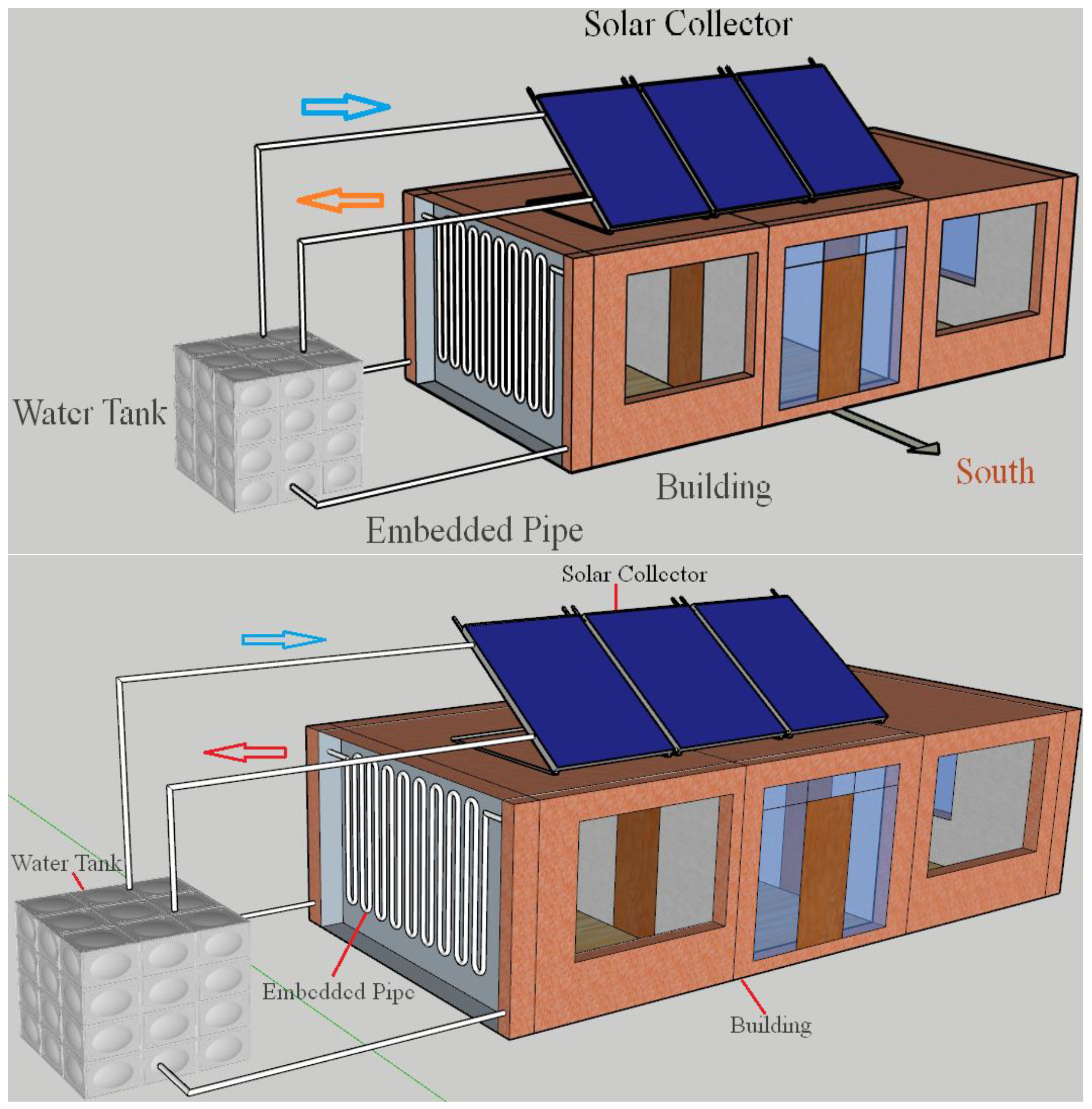
Figure 2.
Scheme of the SEPES simulation model in TRNSYS.

Figure 3.
The layout of the typical building in this study.

Figure 4.
Annual outdoor temperature and natural room temperature in Beijing.
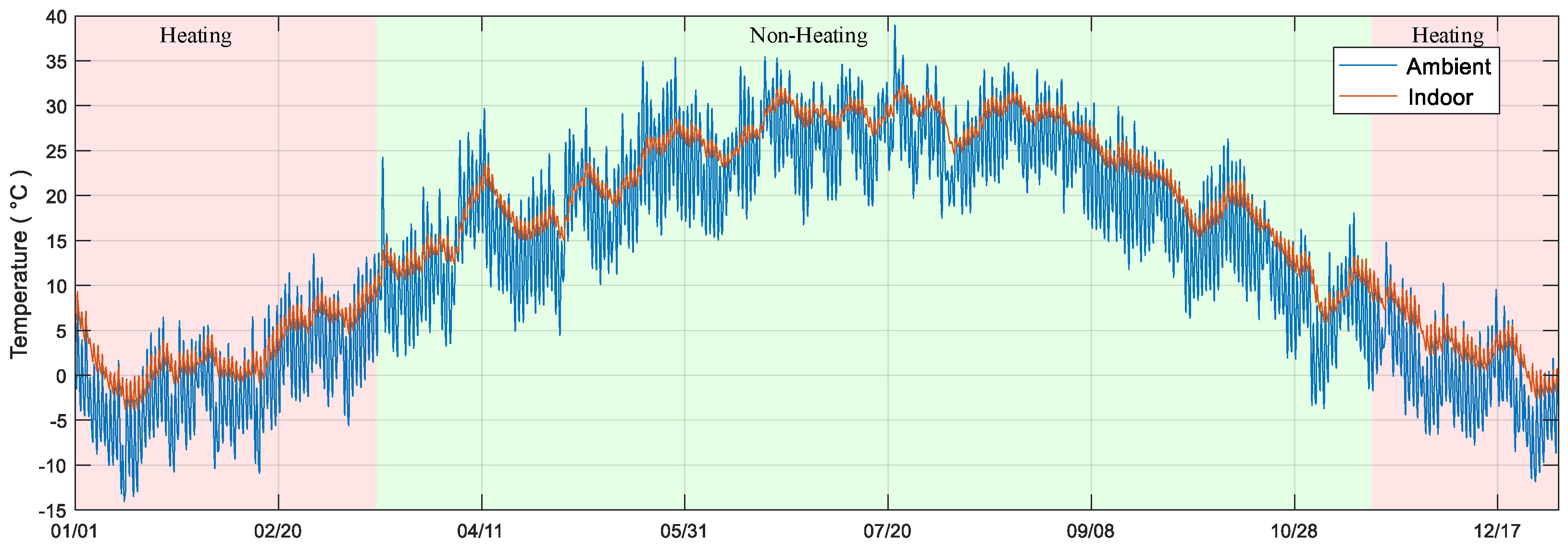
Figure 5.
Room temperatures throughout the entire heating season following the activation of the solar embedded pipe temperature control system.
Figure 5.
Room temperatures throughout the entire heating season following the activation of the solar embedded pipe temperature control system.
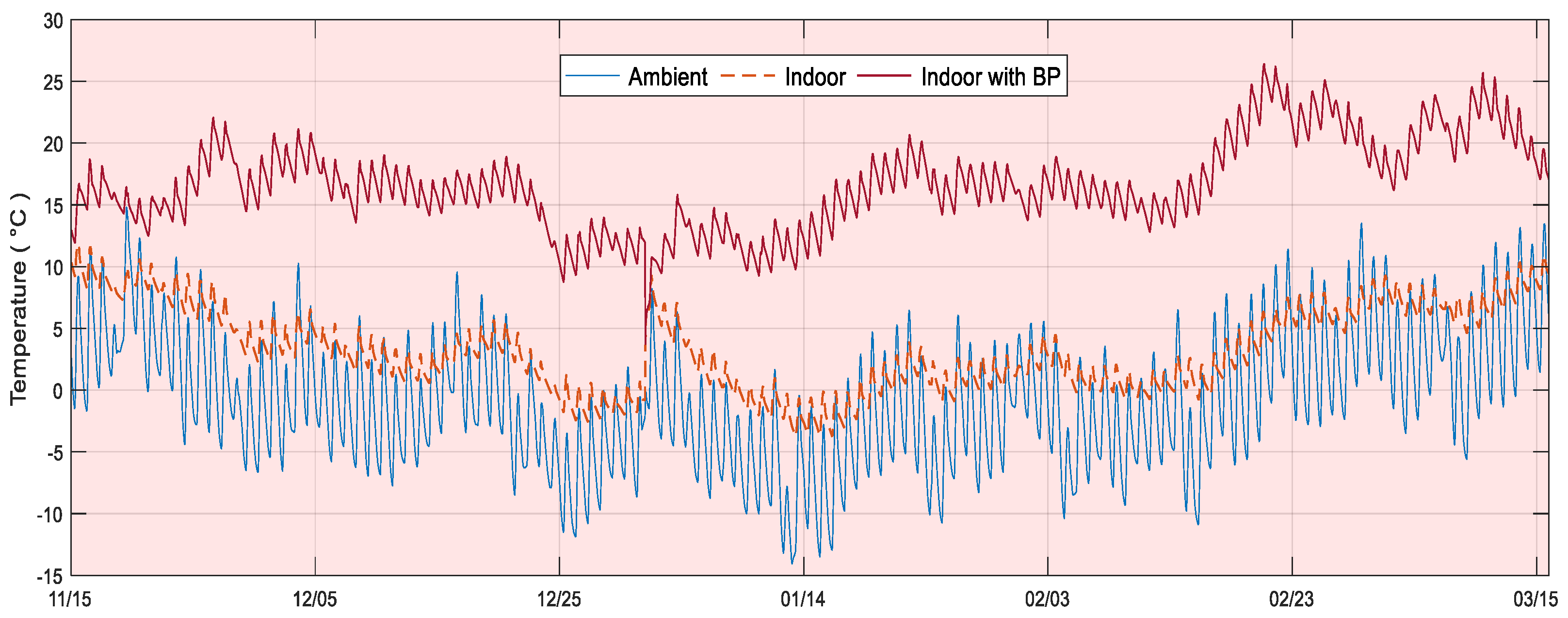
Figure 6.
Comparison of heating energy consumption between traditional buildings and SEPES.

Figure 7.
(a) Variations in outdoor and indoor temperatures throughout January 15th; (b) Comparative analysis of the internal surface temperatures of walls facing in different orientations in two cases; (c) Inlet and outlet water temperatures of the SEPES on walls facing in different orientations; (d) Sankey diagram of the flow of energy.

Figure 8.
The impact of key design parameters of the SEPES on the building’s annual heating load/(a) Area of solar chimney; (b) Tank volume; (c) Circulation flow of solar chimney; (d) Circulation flow of embedded pipe.
Figure 8.
The impact of key design parameters of the SEPES on the building’s annual heating load/(a) Area of solar chimney; (b) Tank volume; (c) Circulation flow of solar chimney; (d) Circulation flow of embedded pipe.

Figure 9.
Typical cities from different climate zones selected for this study.
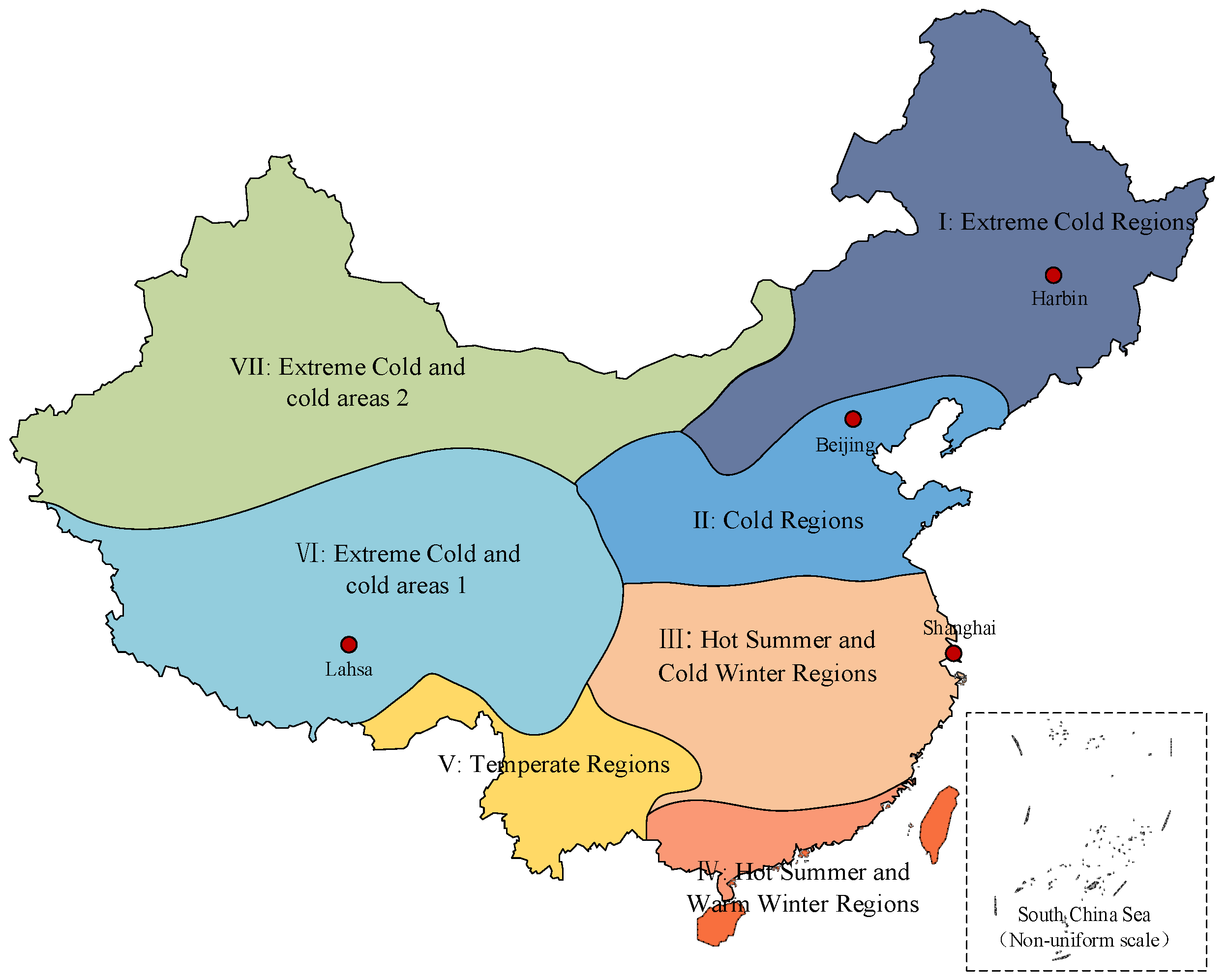
Figure 10.
(a,b) Annual temperature profiles of the four cities; (c) Variation in annual heating loads for typical buildings in the four cities before and after the implementation of the SEPES; (d) Operational durations of the SEPES in these four regions.
Figure 10.
(a,b) Annual temperature profiles of the four cities; (c) Variation in annual heating loads for typical buildings in the four cities before and after the implementation of the SEPES; (d) Operational durations of the SEPES in these four regions.


Table 1.
Existing Similar Studies.
| Reference | Cooling/Heating | Weather | Model | Results of Research |
|---|---|---|---|---|
| [2] | H | Mediterranean | 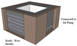 | The annual heating load has the potential to be decreased by 15–43%. |
| [15] | H, C | / | 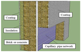 | The power benefit associated with the wall modifications ranges from 2 W to 39 W. |
| [19] | C | / | 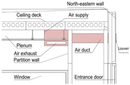 | The wall radiant cooling system has the capability to supply energy for cooling in the range of 29–59 W/. |
| [21] | C | / | 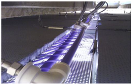 | The wall contributed minimal cooling when the MTC inlet water temperature matched the indoor air temperature. |
| [29] | C | / |  | Reducing the inlet water temperature from 24 °C to 15 °C, while maintaining a constant flow rate of 4 L/min, resulted in an average air temperature decrease exceeding 1.5 °C. |
| [33] | H | / | 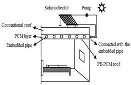 | The total energy demand for room heating can be decreased by 54% when employing a PE–PCM roof. |
| [34] | H, C | Five typical climate regions of China. | 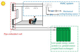 | In climates characterized by hot summers and mild winters, the reductions in building cooling load are noticeably smaller. |
Table 2.
Components and their functions in the coupled simulation platform.
| Module Name | Calling Components | Function |
|---|---|---|
| Solar collector | Type 73 | Models the thermal performance of a theoretical flat plate collector |
| Single-speed pump | Type 114 | Models a single (constant) speed pump that is able to maintain a constant fluid outlet mass flow rate |
| Cylindrical Storage Tank | Type 158 | Models a fluid-filled, constant volume storage tank |
| Weather data | Weather data | Provides outdoor temperature and humidity and calculates solar radiation |
| Outputs | Type 65d | Analyzes the calculation results of each component |
Table 3.
Designed parameters of the SEPES.
| Design Parameter | Description Value | Design Parameter | Description Value |
|---|---|---|---|
| Solar collector | Water tank | ||
| Number in series | 1 | Tank volume | 10 |
| Collector area | 80 | Loss coefficient of tank | 3.35 |
| Fluid specific heat in SC | 4.19 | Pump of wall | |
| Absorptance of absorber plate | 0.9 | Number in series | 4 |
| Number of pumps | 1 | Rated power of pump | 180 W |
| Rated power of pump | 100 W |
Table 4.
Thermo-physical parameters of the building envelope.
| Material Layers | Convective Heat Transfer Coefficient () | U-Value () | |||
|---|---|---|---|---|---|
| Name | Thickness (mm) | Interior | Lateral | ||
| External Wall | Plaster | 2.5 | 3.06 | 17.78 | 0.6 (E, W, N) 0.65 (S) |
| Brick | 370 (E, W, N) 240 (S) | ||||
| Insulation | 48 | ||||
| Floor and Interior walls | Insulation | 30 | 3.06 | 3.06 | 1.0 |
| Concrete | 120 | ||||
| Roof | Insulation | 80 | 3.06 | 17.78 | 0.45 |
| Concrete | 240 | ||||
| External window | Glass | 4 | 3.06 | 17.78 | 3.2 |
| Air | 3.2 | ||||
| Glass | 4 | ||||
Disclaimer/Publisher’s Note: The statements, opinions and data contained in all publications are solely those of the individual author(s) and contributor(s) and not of MDPI and/or the editor(s). MDPI and/or the editor(s) disclaim responsibility for any injury to people or property resulting from any ideas, methods, instructions or products referred to in the content. |
© 2024 by the authors. Licensee MDPI, Basel, Switzerland. This article is an open access article distributed under the terms and conditions of the Creative Commons Attribution (CC BY) license (https://creativecommons.org/licenses/by/4.0/).
Share and Cite
MDPI and ACS Style
Wang, L.; Onn, C.C.; Chew, B.T.; Li, W.; Li, Y. Numerical Study of the Solar Energy-Powered Embedded Pipe Envelope System. Buildings 2024, 14, 613. https://doi.org/10.3390/buildings14030613
AMA Style
Wang L, Onn CC, Chew BT, Li W, Li Y. Numerical Study of the Solar Energy-Powered Embedded Pipe Envelope System. Buildings. 2024; 14(3):613. https://doi.org/10.3390/buildings14030613
Chicago/Turabian StyleWang, Linfeng, Chiu Chuen Onn, Bee Teng Chew, Wuyan Li, and Yongcai Li. 2024. "Numerical Study of the Solar Energy-Powered Embedded Pipe Envelope System" Buildings 14, no. 3: 613. https://doi.org/10.3390/buildings14030613
Note that from the first issue of 2016, this journal uses article numbers instead of page numbers. See further details here.