Double Drainage Consolidation Theory of Vertical Drains Based on Continuous Drainage Boundary Conditions


School of Civil and Ocean Engineering, Jiangsu Ocean University, Lianyungang 222005, China
*
Author to whom correspondence should be addressed.
Buildings 2024, 14(4), 1137; https://doi.org/10.3390/buildings14041137
Submission received: 24 February 2024
/
Revised: 6 April 2024
/
Accepted: 10 April 2024
/
Published: 18 April 2024
(This article belongs to the Section Building Energy, Physics, Environment, and Systems)
Abstract
:Conventionally, drainage boundaries are often assumed to be either perfectly permeable or completely impermeable. However, a more realistic approach considers continuous drainage boundaries. In this context, an analytical solution for double drainage consolidation in vertical drains is derived. The proposed method is evaluated against existing solutions and finite element simulations. The study investigates the impact of drainage capacity, soil nonlinearity, smear effect, and well resistance. The results show that the continuous drainage boundary parameters (i.e., b and c) significantly affect the distribution of excess pore water pressure and the consolidation rate. Increasing b and c allows realistic modeling of drainage capacity variations from impermeable to permeable boundaries. Notably, when b ≠ c, the maximum excess pore water pressure plane shifts from the mid-height of the foundation soil, diverging from conventional consolidation theory. Soil nonlinearity (Cc/Ck) and boundary permeability (b and c) jointly affect consolidation. Higher Cc/Ck values correlate with more detrimental consolidation effects. Minimizing disturbance around vertical drains during construction is crucial due to well resistance and smear zone effects, which can significantly slow down consolidation. This study provides an analytical solution considering soil nonlinearity for predicting consolidation in actual engineering scenarios involving vertical drainage trenches.
1. Introduction
Infrastructure is often constructed on reclaimed land using dredged fills in coastal areas. However, the low permeability of dredged fills makes the developed excess pore water pressure more difficult to dissipate. Vertical drains can introduce radial drainage channels in the soil and decrease the seepage path, so they are often used to accelerate the consolidation of dredged fills [1,2,3]. Research on the consolidation theory of vertical drains has been carried out extensively. In 1948, Barron [4] proposed a radial consolidation theory for vertical drain-improved ground for the first time. Since then, many researchers have revised the original theory of Barron [4] in different aspects, such as the introduction of the “equal strain hypothesis” [3,5,6] and the “free strain hypothesis” [7,8,9]. The “equal strain hypothesis” is relatively simple and is suitable for the conditions where the additional load is uniform and the loading area is large enough. The “free strain hypothesis” is more difficult in the calculation, but it can better characterize the actual deformation of the foundation. It is noted that the seepage flow can cause disturbance around vertical drains and the drainage capacity of the sand well itself can degrade with time due to clogging, both of which affect the consolidation characteristics of the soil. Therefore, consolidation theories for sand wells that can consider the well resistance and the smear effect have been developed by many researchers. For the well resistance effect, previous research was mainly focused on the change in permeability coefficient with time or depth in the vertical drain [10,11,12]. For the smear effect, Zhang [13] and Walke [14] proposed that the permeability coefficient in the smear zone could increase in a linear pattern or a parabolic pattern with the distance away from the sand well, based on which two different analytical solutions for vertical drain consolidation were derived [15,16,17].
It should be emphasized that most investigations were carried out to analyze the consolidation problem of vertical drains in an effort to use the most appropriate input parameters for capturing the time-dependent drainage behavior in both the vertical drain and the smear zone. For consolidation problems, there are three components that can influence the accuracy of the calculation except the use of input parameters: the governing equations and the initial and boundary conditions. Among these aspects, the boundary conditions play an important role, as they can significantly affect the dissipation of excess pore water pressure and the consolidation rate. For example, if soil with a vertical drain is packed in an impervious plastic bag, the pore water can never be drained out from the boundary, no matter how the loading is applied and how long the loading time. In reality, the drainage capacity at the boundaries lies within the zero drainage conditions for an impervious boundary and the maximum drainage conditions for a pervious boundary.
The conventional consolidation theory for vertical drain-improved ground is generally developed by assuming that the boundary at the ground surface is completely pervious and the bottom of the soil layer is fully impervious [18,19]. Actually, both boundaries should be characterized as an interface with a drainage capacity that is closer to a state between pervious and impervious in practice, instead of an extreme state. To tackle this limitation, Gray [18] first proposed an impeded boundary, after which extensive efforts have been made in this direction [19,20,21]. However, the physical meaning of impeded boundary conditions is unclear because it cannot quantify the permeability at the boundary interface. Furthermore, the calculation process is difficult. Based on this, Mei et al. [22] proposed a continuous drainage boundary, wherein the dissipation of the excess pore water pressure at the boundary is linked to time. Subsequently, Mei et al. [23] derived an analytical solution for one-dimensional consolidation problems using continuous drainage boundary conditions and compared it with classical one-dimensional consolidation solutions. Zhang et al. [24] extended the application of continuous drainage boundaries to two-dimensional consolidation problems by considering both horizontal and vertical flow. In recent years, Mei et al. [25] h investigated interface parameter estimation methods, addressing the limitations in considering different drainage capacities at the upper and lower boundaries. At present, continuous drainage boundary conditions are predominantly employed in the context of one-dimensional consolidation. However, the consideration of different drainage capacities at the upper and lower interfaces in three-dimensional vertical drainage consolidation remains limited.
In this paper, a closed-form solution is derived for the three-dimensional consolidation problem of sand well-improved ground, where both the top and bottom interfaces are assumed as continuous drainage boundaries. Comparison between the proposed solution and Lu’s solution [26] is conducted to evaluate the effectiveness of the present solution. Additionally, the influence of input parameters for the well resistance and the smear zone on the calculations of excess pore water pressure and consolidation degree is discussed in detail.
2. Drainage Boundary Condition
A consolidation theory has three components: the governing equations and the initial and boundary conditions. Most analytical solutions of conventional consolidation theories are developed based on Terzaghi’s [27] initial and boundary conditions, which are defined as follows:
Initial conditions:
Boundary conditions:
In this equation, u is the excess pore water pressure, z is the depth, t is the consolidation time, and p is the constant instantaneously applied load on the ground surface.
In Equation (1), when z = 0, the developed excess pore water pressure u at the ground surface upon the instantaneously applied surcharge (t = 0) is derived by:
In Equation (2), when t = 0, the excess pore water pressure at the top boundary interface calculated from the boundary conditions can be obtained as:
By comparing Equations (4) and (5), it is found that the initial and boundary conditions are contradictory:
In addition, the conventional consolidation theory regards the top surface as completely pervious and the bottom surface as perfectly impervious, which is contrary to reality. In practice, a drainage boundary is expected to have the following characteristics:
- (1)
- At the initial time (t = 0), the excess pore water pressure at any depth cannot dissipate, which means ;
- (2)
- As time goes by, the excess pore water pressure at the boundary decreases monotonously;
- (3)
- When the consolidation time is sufficiently long, the excess pore water pressure in the soil is completely dissipated, that is, when , u = 0.
Mei et al. [22] proposed continuous drainage boundary conditions using a negative exponential function that can fulfill all above features, as follows:
In this equation, b is the interface parameter, which reflects the time-dependent drainage capacity at the boundary. The parameter b can be experimentally derived by back-calculating the variations in excess pore water pressure at a boundary interface in the laboratory or in the field and is positively proportional to the drainage capacity at the boundary interface. Equation (6) has the following features: , when t = 0 and when b = 0, satisfying the initial conditions; when , enabling the excess pore water pressure to reduce to zero at infinite time; and when , degenerating the continuous drainage boundary into a completely pervious drainage boundary.
For the three-dimensional consolidation problem of vertical drain-improved ground under a constant load, the contradiction between the initial and boundary conditions in conventional theories still exist. Therefore, Equation (6) is employed to derive the double drainage consolidation theory for vertical drains.
3. Double Drainage Consolidation for Vertical Drains
3.1. Assumptions
The double drainage model for vertical drain-improved ground is idealized as shown in Figure 1, where , , and are the radius of the vertical drain, the smear zone, and the intact zone, respectively; and are the radial and vertical permeability coefficients of the surrounding soil, respectively; and are the permeability coefficients of the smear area and the vertical drain, respectively, which can be used to characterize the smear effect and the well resistance of the vertical drain. In addition, is the constant instantaneously applied load, and H is the depth of the ground. Sand cushions are arranged at both the top and bottom boundaries to enable the dissipation of excess pore water pressure at the drainage interfaces.
The establishment of the double drainage consolidation solution for vertical drains is based on the following assumptions:
- (1)
- The equal strain hypothesis is adopted as the surcharge load is uniformly distributed over the large ground surface, and the seepage flow can be described by Darcy’s law;
- (2)
- At any time, the amount of water flowing into the vertical drain from the surrounding soil is equal to the amount that is discharged at drainage boundaries from the vertical drain;
- (3)
- During the process of consolidation, the permeability and compression coefficients remain unchanged;
- (4)
- The contribution of the soil’s self-weight to the consolidation process is ignored.
3.2. Derivation of Governing Equation
- (1)
- Strain equilibrium
The surcharge load is applied uniformly and instantly on the ground surface. The assumption of equal strain yields the following equations:
where is the volumetric strain, being equivalent to the vertical strain, since there is no confinement in the lateral direction that can cause lateral strains; Es is the modulus of compression of the ground soil; is the total stress, and ; and are the excess pore-water pressure and the average excess pore water pressure in the soil, respectively.
- (2)
- Seepage flow continuity
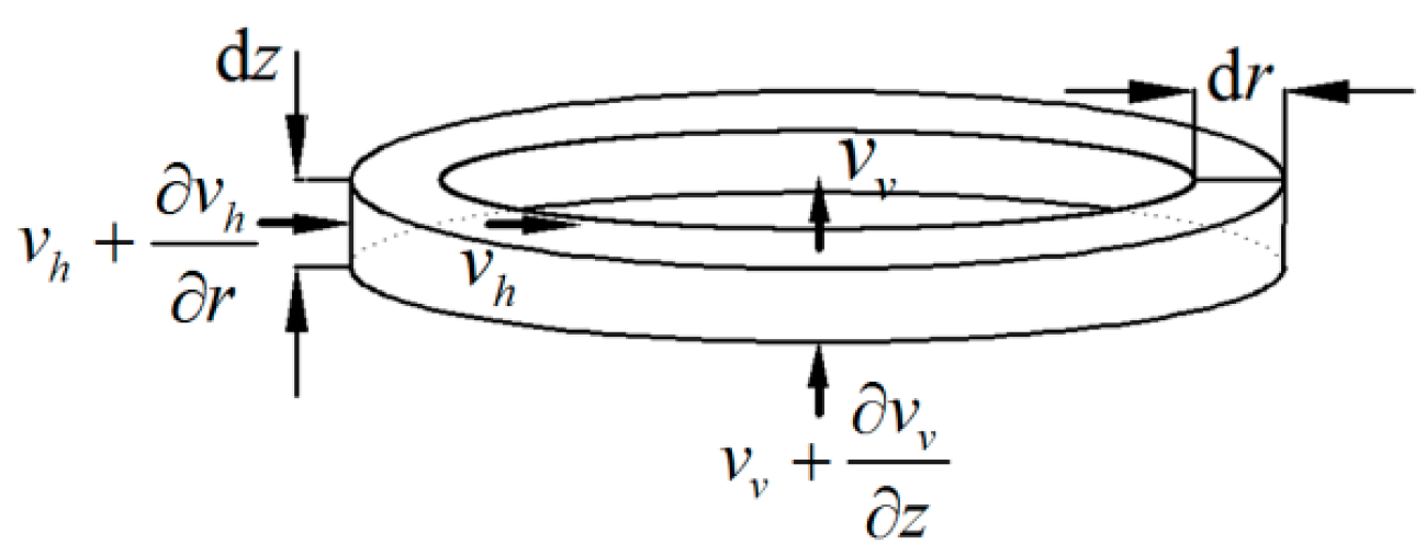
A unit ring with a height of and a thickness of is taken from the vertical drain-improved ground model, as shown in Figure 2. The flow velocities from the inner surface and the upper surface of the unit ring model are assumed to be and , respectively. The flow velocities from the outside surface and the bottom surface of the unit ring mode are and , respectively.
The change of seepage flow through the unit ring model can be expressed as follows:
The volume change of the unit ring model can be derived as follows:
It is assumed that the volume change in the unit ring is simply induced by the seepage flow, i.e., , and the following equation can then be obtained:
The seepage flow is described by Darcy’s law as:
Substituting Equation (12) into Equation (11) gives:
According to the study by Lu [26], Equation (13) can be written as Equation (14) to avoid the derivation of the piecewise function caused by the difference in permeability coefficient between the smear zone and the intact zone.
where
In Equation (16), is a constant. Since both the permeability and compression coefficients are kept constant through the consolidation process, the following equation is derived:
3.3. Derivation of Analytical Solution
As described in Section 3.2, the main governing equations for the vertical drain-improved ground with double continuous drainage boundary conditions could be derived under the following conditions:
Initial conditions:
Boundary conditions:
It should be emphasized that the boundary conditions at the bottom are also characterized using the proposed continuous drainage boundary conditions, but with a different interface parameter c. The parameter c preserves the same definition of the interface parameter b described in Section 2. Different notation is used herein for clarity in the derivation.
Equation (14) is integrated twice with respect to r to derive the following equation:
where .
Substituting Equation (23) into Equation (8) yields:
where J is a constant related to the properties of the vertical drain and can be calculated by:
where is the radius ratio of the smear zone to the vertical drain; and is the radius ratio of the intact zone to the vertical drain.
The derivative of r in Equation (23) can be solved and substituted into Equation (17), from which Equation (25) is obtained, as follows:
Combining Equations (24) and (25) yields:
Equations (7) and (26) are substituted into Equation (24) to eliminate the terms of and , and then the equation can be expressed by .
where , , and are three constants related to the parameters of the vertical drain and the surrounding soil.
Equation (27) can be solved with the initial conditions (18), and the boundary conditions (20) and (21). By homogenizing the boundary conditions, the developed excess pore water pressure at an arbitrary time and spatial location can be calculated, as follows:
For the homogenized governing equation, the initial and boundary conditions are written as follows:
Initial conditions:
Boundary conditions:
Subsequently, the eigenfunction expansion method is employed in this investigation to solve the double drainage solution for vertical drains, as follows:
where , m = 1, 2, 3…
Substituting Equation (28) into Equation (27) gives:
Substituting Equation (32) into Equation (33), according to the Fourier transform, gives:
Equation (34) is then simplified into Equation (35), as follows:
where , , and .
The following equation is obtained by solving Equation (35) with the initial conditions (29):
Substituting Equation (36) into Equation (32) yields:
Then, the excess pore water pressure in the vertical drain can be obtained by substituting Equation (37) into Equation (28), as follows:
According to Equation (26), the average excess pore water pressure in the vertical drain-improved ground can be derived as:
The average consolidation degree can be calculated based on the ratio between the average excess pore water pressure and the applied load by:
Substituting Equations (38) and (26) into Equation (40), the average consolidation degree for the double drainage problem of vertical drain-improved ground with continuous boundary condition can be obtained, as follows:
3.4. Evaluation of the Proposed Solution
In order to assess the effectiveness of the proposed solution, degeneration to the developed method is conducted, and the calculation is compared with existing solutions of Lu [26] and Xie and Zeng [28]. In the double drainage consolidation theory, the continuous drainage interface at the bottom boundary cannot be directly degraded into an impervious one by mathematical methods. For one-dimensional consolidation, if the drainage capacities at the top and bottom interfaces are considered to be identical, i.e., b = c, the excess pore water pressure in the soil could have a maximum value at the mid-height, which distributes symmetrically with respect to the plane of maximum excess pore water pressure, given that the soil’s self-weight is neglected [29]. The schematic illustration of the plane of maximum excess pore water pressure at the mid-height of the foundation soil (i.e., H/2) is depicted in Figure 3. On this basis, the conventional one-dimensional consolidation theory can be used to calibrate the present solution.
According to Section 2, when the interface parameter approaches infinity, the continuous drainage boundary conditions can be degraded to the conventional completely pervious boundary conditions.
Therefore, the assumption of b = c→∞ and h = H/2 can simplify the double continuous drainage consolidation model into a double drainage problem with two pervious boundaries, and the average consolidation degree is reduced to Equation (42), as follows:
where , and .
Obviously, Equation (42) is consistent with the corresponding equation of Lu [26] for a single drainage problem with a pervious boundary at the top and an impervious boundary at the bottom derived using the conventional consolidation theory.
If kv = 0, Equation (42) can be further reduced to a consolidation model that only considers the radial drainage. The average degree of consolidation is then calculated as follows:
where .
This equation is consistent with the result obtained by Xie and Zeng [28].
Due to the symmetry of the distribution of excess pore water pressure, the results of average excess pore water pressure at the depth of 0–4 m for a soil medium with a total thickness of 8 m calculated using the proposed method in Equation (39) are plotted in Figure 4, along with the calculated curves for a single drainage problem of a soil medium with a total thickness of 4 m according to Lu’s solution [26]. Parameters used in the calculation are obtained from a coastal reclamation project in Cangnan County, Zhejiang Province, China, as shown in Table 1. The time factor for the ground soil in the horizontal direction is defined as .
4. Parametric Analysis
4.1. Average Excess Pore Water Pressure
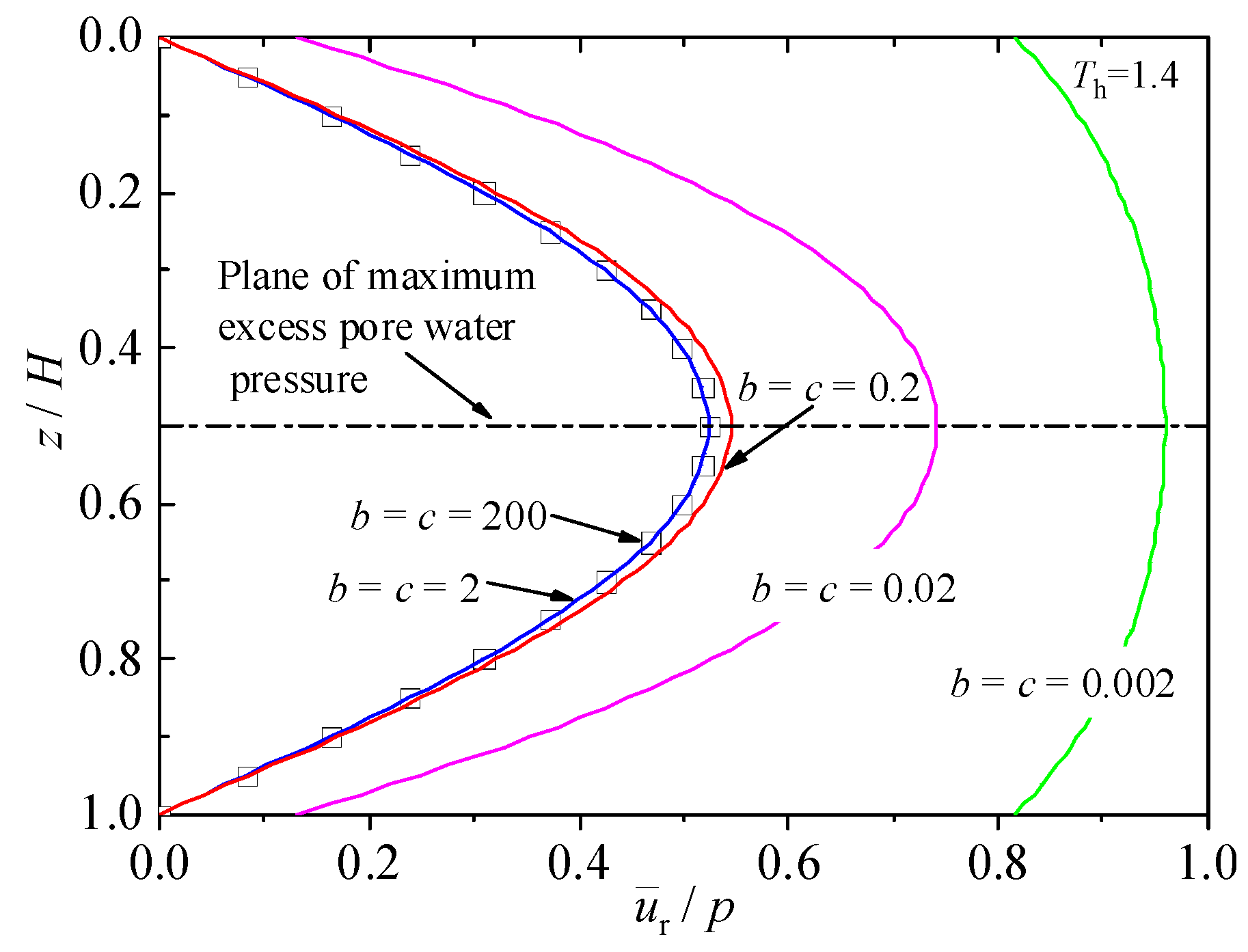
The drainage capacities at the top and bottom boundaries (i.e., interface parameters b and c) have a significant influence on the dissipation of average excess pore water pressure, which can directly reflect the consolidation process. Figure 5 illustrates the variations in average excess pore water pressure with depth for vertical drain-improved ground with equal drainage capacities at both the top and bottom boundary interfaces (i.e., b = c) at a time factor of Th = 1.4 (equivalent to t = 100 d). It can be seen that the average excess pore water pressure increases with the decrease in interface parameter. The average excess pore water pressure curve for b = c = 200 coincides with the curve for b = c = 2. Meanwhile, the excess pore water pressures at the top and bottom boundaries are zero. Hence, it can be concluded that a drainage boundary becomes completely pervious when the interface parameter is greater than 2. Unlike the conventional consolidation theory, when the interface parameters are smaller than 2, that is, when both boundary interfaces are in an intermediate drainage state between fully pervious and perfectly impervious, the excess pore water pressures at the boundaries are no longer zero in the proposed solution. As expected, for the case of b =c, the distribution of average excess pore water pressure is symmetrical about the mid-height of the foundation soil, at which the plane of maximum excess pore water pressure is located. The drainage capacity at the boundaries decreases gradually with the decrease in interface parameter, along with which the profile of average excess pore water pressure moves to the right with higher magnitudes at all depths.
In Figure 6, the profiles of average excess pore water pressure in vertical drain-improved ground with different drainage capacities at the top and bottom boundaries (i.e., b ≠ c) at a time factor of Th = 1.4 (equivalent to t = 100 d) are investigated. In all calculations, the interface parameter at the top is adopted as b = 2 to simulate a completely pervious boundary, such that the average excess pore water pressure at the ground surface is always zero. As the interface parameter c at the bottom boundary varies from 0.2 to 0.002, it represents a gradually weakened drainage capacity at the bottom. Therefore, the average excess pore water pressure at the bottom boundary increases gradually from zero with the decrease in c, and the curve of average excess pore water pressure moves to the right. This demonstrates that the dissipation of average excess pore water pressure can be significantly influenced by the drainage capacity at the bottom. Moreover, it is interesting to note that when b ≠ c, the plane of maximum excess pore water pressure is no longer at the mid-height of the foundation soil. With the decrease in c, the plane of maximum excess pore water pressure gradually moves towards to the boundary with a lower drainage capacity.
Additionally, ABAQUS (2017) is widely used in various engineering fields for its powerful nonlinear solver [30,31], and continuous drainage boundaries can be realized through its DISP subroutine [32]. In order to strengthen the validation of the analytical results, Figure 6 compares the theoretical computational analytical solution of the mean overpressure with the numerical solution obtained through the finite element software ABAQUS, and the trends and results of both are very consistent.
The phenomenon of asymmetric distribution of excess pore water pressure without consideration of the soil’s self-weight has not been taken into account in the conventional consolidation theory. In practice, the drainage capacities at both the top and bottom boundaries often differ, and as such, a horizontal drain (i.e., sand cushion) should be set at the plane of maximum excess pore water pressure to efficiently accelerate the consolidation process of the foundation soil. More details regarding the optimization of horizonal drains in clay-drain reclamation can be found in Feng et al. [29].
Figure 7 illustrates the impact of soil nonlinearity. As depicted in the figure, with the increase in the ratio of compression index to permeability index (Cc/Ck), the pore pressure under the same boundary conditions gradually increases, indicating a gradual attenuation of dissipation. This phenomenon is primarily attributed to the elevated Cc/Ck ratio, signifying a gradual decrease in soil permeability. Consequently, the overall permeability of the foundation decreases, leading to a slowdown in pore pressure dissipation. Furthermore, contrasting pore pressure curves for different bottom permeabilities reveal the significant influence of Cc/Ck on the dissipation and distribution of pore pressure, and it diminishes the impact of boundary conditions on pore pressure. For instance, comparing the curve with b = 2, c = 0.2, and Cc/Ck = 0.6 to the curve with b = 2, c = 0.002, and Cc/Ck = 0.3, it is observed that in the upper part of the soil, where the ground permeability is lower, the dissipation of pore pressure is faster. This can be mainly attributed to the improvement in soil permeability resulting from the reduced Cc/Ck value. Hence, it is evident that in the prediction and calculation of soil consolidation, consideration must be given not only to the permeability of the boundary interface but also to the inherent permeability of the soil itself, as it significantly influences the consolidation process.
4.2. Average Consolidation Degree
The variations in average consolidation degree with time factor can intuitively exhibit the consolidation speed. Input parameters, such as the interface parameters, the well resistance, the radius of the smear zone, and the smear permeability coefficient, can all affect the consolidation process. In the parametric study, the parameters defined in Table 1 are employed, and the results are given in Figure 8, Figure 9, Figure 10, Figure 11, Figure 12, Figure 13 and Figure 14.
According to Figure 5, when the interface parameters at both boundaries are b = c = 2, the top and bottom interfaces are completely pervious. Figure 8 presents the consolidation curves calculated for different combinations of equal interface parameters. It can be seen that the consolidation speed gradually decreases with decreases in b and c, since the consolidation curve moves to the right. At a specific time factor, the average consolidation degree becomes smaller when the interface parameter decreases or the drainage capacity at the boundaries reduces. This proves that the drainage capacities at both the top and bottom boundaries can greatly affect the dissipation of excess pore water pressure in the vertical direction. In practice, a completely pervious boundary rarely exists. Therefore, the average consolidation degree could be overestimated for vertical drain-improved ground using the conventional consolidation theory with completely pervious boundary conditions, which is consistent with the observations of Feng et al. [29].
Furthermore, similar to the pore pressure analysis, a comparison between analytical and numerical solutions for the degree of consolidation was undertaken. As illustrated in Figure 9, the results obtained from finite element calculations using ABAQUS exhibit close correspondence to the theoretical calculations proposed in this study. The maximum disparity between the two approaches is approximately 5%, and this difference is even smaller when considering the time required to achieve complete consolidation. This comparison serves as an additional validation of the applicability of the theoretical framework presented in this paper.
Figure 9 illustrates the influence of soil nonlinearity on the average degree of consolidation. As depicted in the graph, both interface parameters and soil nonlinearity exert significant effects on the degree of consolidation. The introduction of nonlinear parameters alters the impact of interface parameters on the average consolidation degree of the soil. Similar to the earlier analysis of excess pore water pressure, nonlinearity affects the overall permeability of the soil. Consequently, when combined with the influence of boundary permeability, this results in a noteworthy alteration in the consolidation curve compared to the scenario where soil nonlinearity is not considered.
In Figure 10, the consolidation curves calculated for vertical drain-improved ground with different combinations of interface parameters are compared. Essentially, the case of b = c can be used as a control for double continuous drainage conditions, against which the interface parameter at the bottom boundary is lowered to a value of c = 0.00001, representing an impervious boundary for single continuous drainage conditions for comparison. The results show that the interface parameter has a significant effect on the average consolidation degree, regardless of the drainage conditions at the boundaries (i.e., single or double drainage model). As expected, the consolidation speed of the double continuous drainage model is much faster than that of the single continuous drainage model, because the vertical seepage path under double drainage conditions is much shorter than that under single drainage conditions. In a conventional manner, the average consolidation degree of vertical drain-improved ground is calculated by the single drainage model, where the consolidation speed can be underestimated. The results also demonstrate that if a ground improvement project requires a shorter consolidation time, pre-setting a horizontal drain (i.e., sand cushion) at the bottom is suggested before filling dredged materials, which can significantly accelerate the consolidation speed.
In Figure 11, the influence of different permeability coefficients of the vertical drain on the average consolidation degree is investigated. The magnitude of the permeability coefficient of the vertical drain can directly represent the well resistance. It shows that with the increase in kw, the permeability of the vertical drain becomes higher, leading to a less significant well resistance effect. Due to the weakened well resistance effect, the consolidation curve moves to the left, where the average consolidation degree is higher at a given time factor, and the consolidation speed is accelerated. For a low value of kw, the well resistance effect becomes more apparent, and the seepage flow through the vertical drain is reduced. Therefore, it is of significance to increase the drainage capacity of vertical drains (i.e., sand well) in ground improvement projects.
Figure 12 illustrates the influence of the radius of the smear zone on the average consolidation degree. Again, the parameter s = rs/rw represents the radius ratio of the smear zone to the vertical drain. A larger s value represents the case where a vertical drain can cause a greater extent of disturbance around a vertical drain, corresponding to a larger radius of the smear zone. It can be seen that the consolidation speed obviously accelerates as s decreases, where the consolidation curve moves to the left (i.e., a higher average consolidation degree at a specific time factor).
The influence of the permeability coefficient in the smear zone on the average consolidation degree is evaluated in Figure 13. The ratio of ks/kh represents the permeability coefficient ratio of the smear zone to the intact zone. With the decrease in ks/kh, the permeability coefficient of the smear zone decreases, that is, the disturbance becomes more critical. When ks/kh = 1, the permeability coefficient of the smear area is the same as that of the intact zone, namely, the vertical drain does not result in the smear effect. From Figure 13, it is found that the consolidation speed increases greatly as ks/kh increases. To sum up, the range and the permeability coefficient of the smear zone have significant influences on the average consolidation degree, since the smear effect can reduce the radial seepage flow. Therefore, the disturbance around vertical drains should be reduced as much as possible during the installation of vertical drains.
In Figure 14, a comparison of the average consolidation degree under different assumptions about the vertical drain is carried out. An ideal well refers to a vertical drain model with perfectly pervious drainage boundaries at both the top and bottom interfaces, and there is no smear effect or well resistance effect, i.e., b = c = 2, ks = kh, and the permeability coefficient of the vertical drain is 10kw. A well resistance model refers to the case with completely pervious drainage boundaries at the top and bottom interfaces, in which the well resistance effect is considered but not the smear effect, i.e., b = c = 2, ks = kh, and the permeability coefficient of the vertical drain is 0.1kw. A smear model corresponds to the situation with fully pervious drainage boundaries at both the top and bottom, where the smear zone is taken into account but not the well resistance effect, i.e., b = c = 2, ks = 0.1kh, and the permeability coefficient of the vertical drain is 10kw. A realistic well model represents the conditions in which both the top and bottom interfaces are characterized by time-dependent continuous drainage boundaries, and the drainage capacities at the two boundaries are different. Meanwhile, the realistic well model takes into account the well resistance effect and the smear effect, i.e., b = 0.2, c = 0.02, ks = 0.1kh, and the permeability coefficient of the vertical drain is kw. It can be seen from Figure 12 that the consolidation speed calculated using the ideal well model is significantly higher than that derived using other models. The consolidation speed from the realistic well model is the lowest, since this model can consider all of the effects, including the time-dependent drainage capacity at interfaces with continuous drainage boundary conditions, the well resistance effect, and the smear effect.
The choice of interface parameters, the well resistance, and the smear zone are all important factors that can affect the consolidation process of vertical drain-improved ground. In the calculation, ignoring one of these factors can lower the accuracy of the consolidation prediction. In practice, installation of a horizontal drain (i.e., sand cushion) is an effective way to accelerate the consolidation rate. Meanwhile, it is imperative to increase the permeability of vertical drains and reduce the disturbance around vertical drains.
5. Conclusions
Traditional consolidation theories for most vertical drain-improved soil layers are based on the assumption of an impermeable lower boundary and a permeable upper boundary. However, in practical applications, this may not always hold true. Under constant instantaneous loading, the initial and boundary conditions in existing methods are mathematically contradictory. To address this issue, we introduce continuous drainage boundary conditions to characterize the time-dependent drainage behavior at the boundaries and compare the results with those obtained using existing finite element numerical methods. We solve the three-dimensional consolidation of vertical drain-improved ground. We then conduct parameter studies to investigate soil consolidation behavior. The following conclusions can be drawn:
- (1)
- By varying the interface parameters b and c, continuous boundary conditions can simulate drainage capacity changes over time from fully permeable to completely impermeable, overcoming the limitations of traditional boundary conditions that can only model extreme drainage states.
- (2)
- Boundary drainage capacity significantly influences the consolidation process. As the interface parameters decrease, the drainage capacity of the continuous drainage boundary decreases, leading to a noticeable reduction in the consolidation rate of the foundation soil.
- (3)
- Under continuous drainage boundary conditions, when the drainage capacities of the upper and lower interfaces differ, the maximum excess pore water pressure plane is no longer located at the mid-high level of the foundation soil. This achievement is challenging for traditional consolidation theories.
- (4)
- The interaction between soil nonlinearity and foundation boundary permeability has a significant impact on consolidation characteristics. Soil nonlinearity parameter Cc/Ck with a value of 0 (without considering the nonlinearity) results in the shortest consolidation time, while on the contrary, larger values of Cc/Ck (Cc/Ck = 0.9) are less favorable for pore pressure dissipation or soil consolidation.
- (5)
- The consolidation rate under dual drainage conditions is significantly faster than under single drainage conditions. The drainage capacity of the bottom boundary should not be overlooked, and horizontal drainage trenches (such as sand cushions) can be installed before filling with dredged material to accelerate the consolidation process.
- (6)
- The well resistance effect and the smear effect have obvious adverse influences on the dissipation of average excess pore water pressure. Therefore, it is important to reduce the disturbance around vertical drains and increase the permeability of vertical drains as far as possible.
Author Contributions
Writing—original draft, Investigation, Funding acquisition, Y.Z.; Validation, Resources, Data curation, B.H.; Writing—review & editing, K.M.; Visualization, J.Z.; Formal analysis, Conceptualization, Supervision, M.Z.; Project administration, L.K. All authors have read and agreed to the published version of the manuscript.
Funding
This research was funded by the National Natural Science Foundation of China (Grant Number 52108322), and the Natural Science Foundation of the Jiangsu Higher Education Institutions of China (Grant Number 23KJB560004).
Data Availability Statement
The data that support the findings of this study are available from the corresponding author upon reasonable request.
Conflicts of Interest
The authors declare no conflicts of interest.
References
- Chan, C.-M. Geo-Parametric Study of Dredged Marine Clay with Solidification for Potential Reuse as Good Engineering Soil. Environ. Earth Sci. 2016, 75, 941. [Google Scholar] [CrossRef]
- Chai, J.; Anda, R. Cyclic Loads Induced Consolidation Deformation of PVD Unit Cells. Transp. Geotech. 2023, 38, 100911. [Google Scholar] [CrossRef]
- Xu, Z.; Cui, P.; Cao, W.; Zhang, X.; Zhang, J. Large-Strain Nonlinear Consolidation of Sand-Drained Foundations Considering Vacuum Preloading and the Variation in Radial Permeability Coefficient. Buildings 2023, 13, 2843. [Google Scholar] [CrossRef]
- Barron, R.A. Consolidation of Fine-Grained Soils by Drain Wells by Drain Wells. Trans. Am. Soc. Civ. Eng. 1948, 113, 718–742. [Google Scholar] [CrossRef]
- Hansbo, S.; Jamiolkowski, M.; Kok, L. Consolidation by Vertical Drains. Géotechnique 1981, 31, 45–66. [Google Scholar] [CrossRef]
- Wang, Z.-F.; Shen, S.-L.; Ho, C.-E.; Kim, Y.-H. Investigation of Field-Installation Effects of Horizontal Twin-Jet Grouting in Shanghai Soft Soil Deposits. Can. Geotech. J. 2013, 50, 288–297. [Google Scholar] [CrossRef]
- Yoshikuni, H.; Nakanodo, H. Consolidation of Soils by Vertical Drain Wells with Finite Permeability. Soils Found. 1974, 14, 35–46. [Google Scholar] [CrossRef] [PubMed]
- Basack, S.; Nimbalkar, S. Free strain analysis of the performance of vertical drains for soft soil improvement. Geomech. Eng. 2017, 13, 963–975. [Google Scholar]
- Geng, X.; Yu, H.-S. A Large-Strain Radial Consolidation Theory for Soft Clays Improved by Vertical Drains. Géotechnique 2017, 67, 1020–1028. [Google Scholar] [CrossRef]
- Chai, J.-C.; Miura, N. Investigation of Factors Affecting Vertical Drain Behavior. J. Geotech. Geoenviron. Eng. 1999, 125, 216–226. [Google Scholar] [CrossRef]
- Kim, R.; Hong, S.-J.; Lee, M.-J.; Lee, W. Time Dependent Well Resistance Factor of PVD. Mar. Georesour. Geotechnol. 2011, 29, 131–144. [Google Scholar] [CrossRef]
- Xu, C.; Zhang, J.; Liu, Z. Large-Strain Elastic Viscoplastic Consolidation of Vertical Drains with Non-Darcian Flow Incorporating Well Resistance and Smear Zone. Int. J. Geomech. 2023, 23, 04022246. [Google Scholar] [CrossRef]
- Zhang, Y.G.; Xie, K.H.; Wang, Z. Consolidation Analysis of Composite Ground Improved by Granular Columns Considering Variation of Permeability Coefficient of Soil. In Ground Modification and Seismic Mitigation, Proceedings of the GeoShanghai Conference, Shanghai, China, 6–8 June 2006; American Society of Civil Engineers: Reston, VA, USA, 2006; pp. 135–142. [Google Scholar] [CrossRef]
- Walker, R.; Indraratna, B. Vertical Drain Consolidation with Parabolic Distribution of Permeability in Smear Zone. J. Geotech. Geoenviron. Eng. 2006, 132, 937–941. [Google Scholar] [CrossRef]
- Nguyen, B.-P.; Kim, Y.-T. Radial Consolidation of PVD-Installed Normally Consolidated Soil with Discharge Capacity Reduction Using Large-Strain Theory. Geotext. Geomembr. 2019, 47, 243–254. [Google Scholar] [CrossRef]
- Azari, B.; Fatahi, B.; Khabbaz, H. Assessment of the Elastic-Viscoplastic Behavior of Soft Soils Improved with Vertical Drains Capturing Reduced Shear Strength of a Disturbed Zone. Int. J. Geomech. 2016, 16, B4014001. [Google Scholar] [CrossRef]
- Wu, X.-T.; Liu, J.-N.; Xie, Z.-M. Deformation and Strength Characteristics of Marine Soft Soil Treated by Prefabricated Vertical Drain-Assisted Staged Riprap under Seawall Construction. Buildings 2023, 13, 2322. [Google Scholar] [CrossRef]
- Gray, H. Simultaneous Consolidation of Contiguous Layers of Unlike Compressible Soils; American Society of Civil Engineers: Reston, VA, USA, 1944. [Google Scholar]
- Lei, G.H.; Fu, C.W.; Ng, C.W.W. Vertical-Drain Consolidation Using Stone Columns: An Analytical Solution with an Impeded Drainage Boundary under Multi-Ramp Loading. Geotext. Geomembr. 2016, 44, 122–131. [Google Scholar] [CrossRef]
- Wang, L.; Sun, D.; Li, L.; Li, P.; Xu, Y. Semi-Analytical Solutions to One-Dimensional Consolidation for Unsaturated Soils with Symmetric Semi-Permeable Drainage Boundary. Comput. Geotech. 2017, 89, 71–80. [Google Scholar] [CrossRef]
- Chen, H.-X.; Feng, S.-J.; Zhu, Z.-W.; Gao, L.; Chen, Z.-L.; Wang, S.-R. One-Dimensional Self-Weight Consolidation of Layered Soil under Variable Load and Semi-Permeable Boundary Condition. Comput. Geotech. 2023, 159, 105431. [Google Scholar] [CrossRef]
- Mei, G.; Chen, Q. Solution of Terzaghi One-Dimensional Consolidation Equation with General Boundary Conditions. J. Cent. South Univ. 2013, 20, 2239–2244. [Google Scholar] [CrossRef]
- Mei, G.-X.; Lok, T.; Xia, J.; Wu, S. One-Dimensional Consolidation with Asymmetrical Exponential Drainage Boundary. Geomech. Eng. 2014, 6, 47–63. [Google Scholar] [CrossRef]
- Zhang, Y.; Wu, W.; Mei, G.; Duan, L. Three-Dimensional Consolidation Theory of Vertical Drain Based on Continuous Drainage Boundary. J. Civ. Eng. Manag. 2019, 25, 145–155. [Google Scholar] [CrossRef]
- Mei, G.; Feng, J.; Xu, M.; Ni, P. Estimation of Interface Parameter for One-Dimensional Consolidation with Continuous Drainage Boundary Conditions. Int. J. Geomech. 2022, 22, 04021292. [Google Scholar] [CrossRef]
- Lu, M.-M.; Xie, K.-H.; Guo, B. Consolidation Theory for a Composite Foundation Considering Radial and Vertical Flows within the Column and the Variation of Soil Permeability within the Disturbed Soil Zone. Can. Geotech. J. 2010, 47, 207–217. [Google Scholar] [CrossRef]
- Terzaghi, K. Erdbaumechanik auf Bodenphysikalischer Grundlage; F. Deuticke: Vienna, Austria, 1925. [Google Scholar]
- Xie, K.; Zeng, G. Consolidation Theories for Drain Wells under Equal Strain Condition. Chin. J. Geotech. Eng. 1989, 11, 3–17. [Google Scholar]
- Feng, J.; Ni, P.; Mei, G. One-Dimensional Self-Weight Consolidation with Continuous Drainage Boundary Conditions: Solution and Application to Clay-Drain Reclamation. Int. J. Numer. Anal. Methods Geomech. 2019, 43, 1634–1652. [Google Scholar] [CrossRef]
- Khan, R.M.; Shafighfard, T.; Ali, H.Q.; Mieloszyk, M.; Yildiz, M. Strength prediction and experimental damage investigations of plain woven CFRPs with interacting holes using multi-instrument measurements. Polym. Compos. 2023, 44, 3594–3609. [Google Scholar] [CrossRef]
- Khan, S.A.; Khan, H.A.; Khan, A.; Salamat, S.; Javaid, S.S.; Khan, R.M. Investigation of the mechanical behavior of FDM processed CFRP/Al hybrid joint at elevated temperatures. Thin-Walled Struct. 2023, 192, 111135. [Google Scholar] [CrossRef]
- Ma, K.; Gao, Z.; Wang, J.; Zhang, Y.; Zong, M.; Wu, W.; Mei, G. Nonlinear consolidation finite element analysis of a layered soft soil foundation under multistage loading based on the continuous drainage boundary. Comput. Geotech. 2024, 169, 106220. [Google Scholar] [CrossRef]
Figure 1.
Vertical drain-improved foundation model.

Figure 2.
Unit ring model for seepage flow.

Figure 3.
Definition of the plane of maximum excess pore water pressure in the soil with continuous drainage boundary conditions at both the top and bottom boundaries.
Figure 3.
Definition of the plane of maximum excess pore water pressure in the soil with continuous drainage boundary conditions at both the top and bottom boundaries.

Figure 4.
Comparison of the average excess pore water pressure between this study and Lu’s solution [26].
Figure 4.
Comparison of the average excess pore water pressure between this study and Lu’s solution [26].

Figure 5.
Influence of interface parameters on the profile of average excess pore water pressure for vertical drain-improved ground with equal drainage capacities at both boundaries.
Figure 5.
Influence of interface parameters on the profile of average excess pore water pressure for vertical drain-improved ground with equal drainage capacities at both boundaries.

Figure 6.
Influence of interface parameters on the profile of average excess pore water pressure for vertical drain-improved ground with different drainage capacities at both boundaries.
Figure 6.
Influence of interface parameters on the profile of average excess pore water pressure for vertical drain-improved ground with different drainage capacities at both boundaries.

Figure 7.
Influence of soil nonlinearity on excess pore water pressure dissipation.

Figure 8.
Variation in average consolidation degree with time factor for vertical drain-improved ground with different drainage capacities at both boundaries.
Figure 8.
Variation in average consolidation degree with time factor for vertical drain-improved ground with different drainage capacities at both boundaries.

Figure 9.
Influence of soil nonlinearity on average consolidation degree.

Figure 10.
Comparison of average consolidation degree between single and double continuous drainage consolidation models.
Figure 10.
Comparison of average consolidation degree between single and double continuous drainage consolidation models.

Figure 11.
Influence of well resistance on the average consolidation degree.

Figure 12.
Influence of the radius of the smear zone on the average consolidation degree.

Figure 13.
Influence of the permeability coefficient in the smear zone on the average consolidation degree.
Figure 13.
Influence of the permeability coefficient in the smear zone on the average consolidation degree.

Figure 14.
Comparison of average consolidation degree under different assumptions of vertical drains.
Figure 14.
Comparison of average consolidation degree under different assumptions of vertical drains.


Table 1.
Physical parameters of the soil.
| Depth, H (m) | Permeability Coefficient, (m/d) | (kPa) | Radius, r (m) | |||||
|---|---|---|---|---|---|---|---|---|
| 8 | 4.3 × 10⁻⁴ | 2.16 × 10⁻⁴ | 4.31 × 10⁻⁵ | 1.08 | 2000 | 2.5 | 1 | 0.25 |
Disclaimer/Publisher’s Note: The statements, opinions and data contained in all publications are solely those of the individual author(s) and contributor(s) and not of MDPI and/or the editor(s). MDPI and/or the editor(s) disclaim responsibility for any injury to people or property resulting from any ideas, methods, instructions or products referred to in the content. |
© 2024 by the authors. Licensee MDPI, Basel, Switzerland. This article is an open access article distributed under the terms and conditions of the Creative Commons Attribution (CC BY) license (https://creativecommons.org/licenses/by/4.0/).
Share and Cite
MDPI and ACS Style
Zhang, Y.; Hou, B.; Ma, K.; Zhang, J.; Zong, M.; Kong, L. Double Drainage Consolidation Theory of Vertical Drains Based on Continuous Drainage Boundary Conditions. Buildings 2024, 14, 1137. https://doi.org/10.3390/buildings14041137
AMA Style
Zhang Y, Hou B, Ma K, Zhang J, Zong M, Kong L. Double Drainage Consolidation Theory of Vertical Drains Based on Continuous Drainage Boundary Conditions. Buildings. 2024; 14(4):1137. https://doi.org/10.3390/buildings14041137
Chicago/Turabian StyleZhang, Yi, Benchi Hou, Ke Ma, Jing Zhang, Mengfan Zong, and Lingzhou Kong. 2024. "Double Drainage Consolidation Theory of Vertical Drains Based on Continuous Drainage Boundary Conditions" Buildings 14, no. 4: 1137. https://doi.org/10.3390/buildings14041137
Note that from the first issue of 2016, this journal uses article numbers instead of page numbers. See further details here.