4.1. Curtain Wall with Rigid Brackets (M01 and M02 FE-Models)
In M01 and M02 FE-models, glass lites were modeled by means of S4R 4-node, quadrilateral stress/displacement shell elements with reduced integration and large-strain formulation. The
composite shell option was used to take into account the presence of multiple layers in the laminated glass panel. Five integration points through the thickness of the composite section were taken into account. In addition, to describe the effective geometry of the studied glazing system, a section offset
toffset = 12.26 mm from the centroidal axis was applied to shell elements. Larcher
et al. [
17], by comparing numerical results of layered shell and 3D solid elements, showed that
composite shells can closely represent the behavior of laminated glass panels subjected to air blast loading, specifically when both glass lites fail.
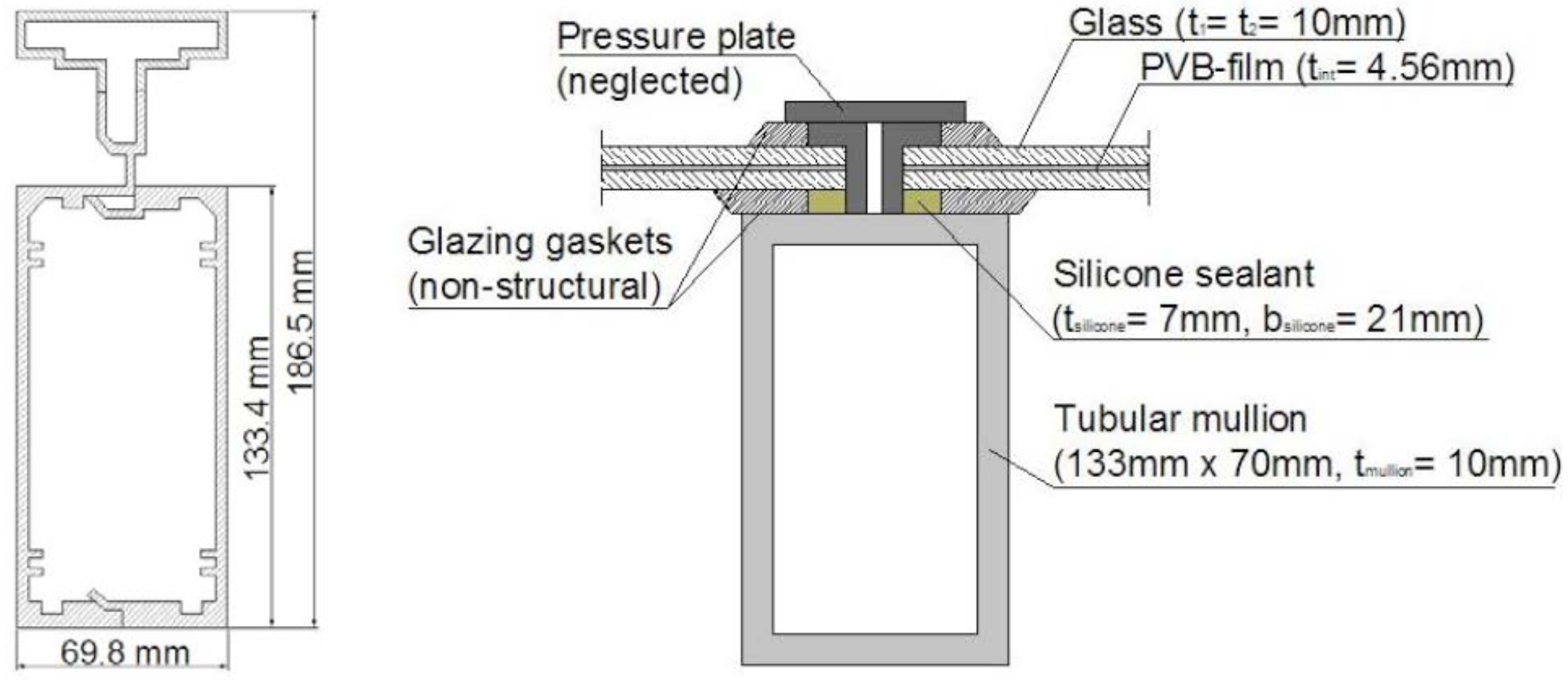
Aluminum mullions and transoms were modeled as three-dimensional beam elements (B31). A simplified 133 mm × 70 mm box cross-section was used to describe their real geometry (with
tmullion = 10 mm a constant thickness;
Ixx = 707 × 10
−6 m
4 and
Iyy = 2.63 × 10
−6 m
4 the moments of inertia). Weggel
et al. [
18] recently demonstrated through bending tests that in similar split mullions the presence of the pressure plate can increase the moments of inertia of the only tubular cross-section. In their work, the inertia along the strong and weak axes respectively increased up to 30% and 11%. Undoubtedly, further investigations should be performed to calculate with accuracy the mechanical properties of the adopted split mullions. Nevertheless, since the aim of this paper is a first investigation of the possible structural effects of the proposed VE devices, the assumption of a simplified box cross-section could constitute an acceptable modeling simplification. In these hypotheses, meshing of the frame was based on 50 mm beam elements (
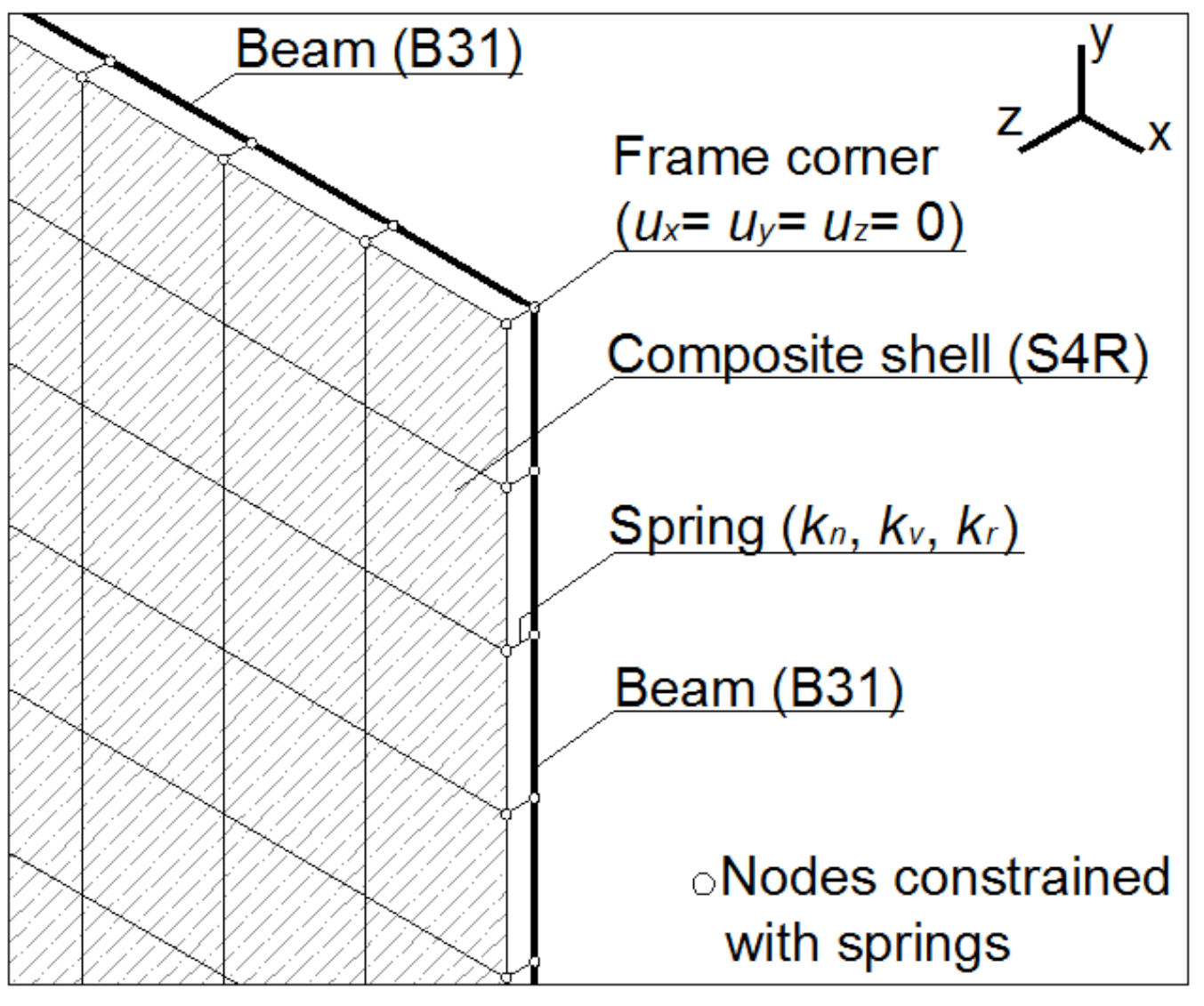
Figure 6).
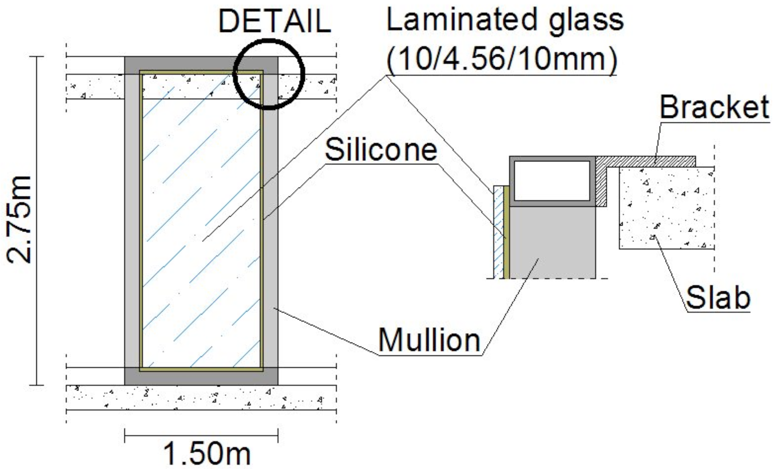
Figure 6.
Modeling detail for the curtain wall with rigid brackets (M01 and M02 FE-models).
Figure 6.
Modeling detail for the curtain wall with rigid brackets (M01 and M02 FE-models).
In addition, in accordance with Weggel
et al. [
18], the screw connection between transoms and mullions was characterized by zero rotational stiffness. Also, this assumption well applies to small displacements, but for the purpose of this work, it is a rational simplification. The end nodes of mullions, directly connected to the brackets, were modeled in the form of pinned-connections [
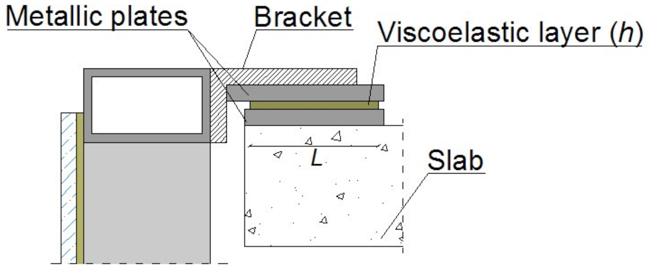
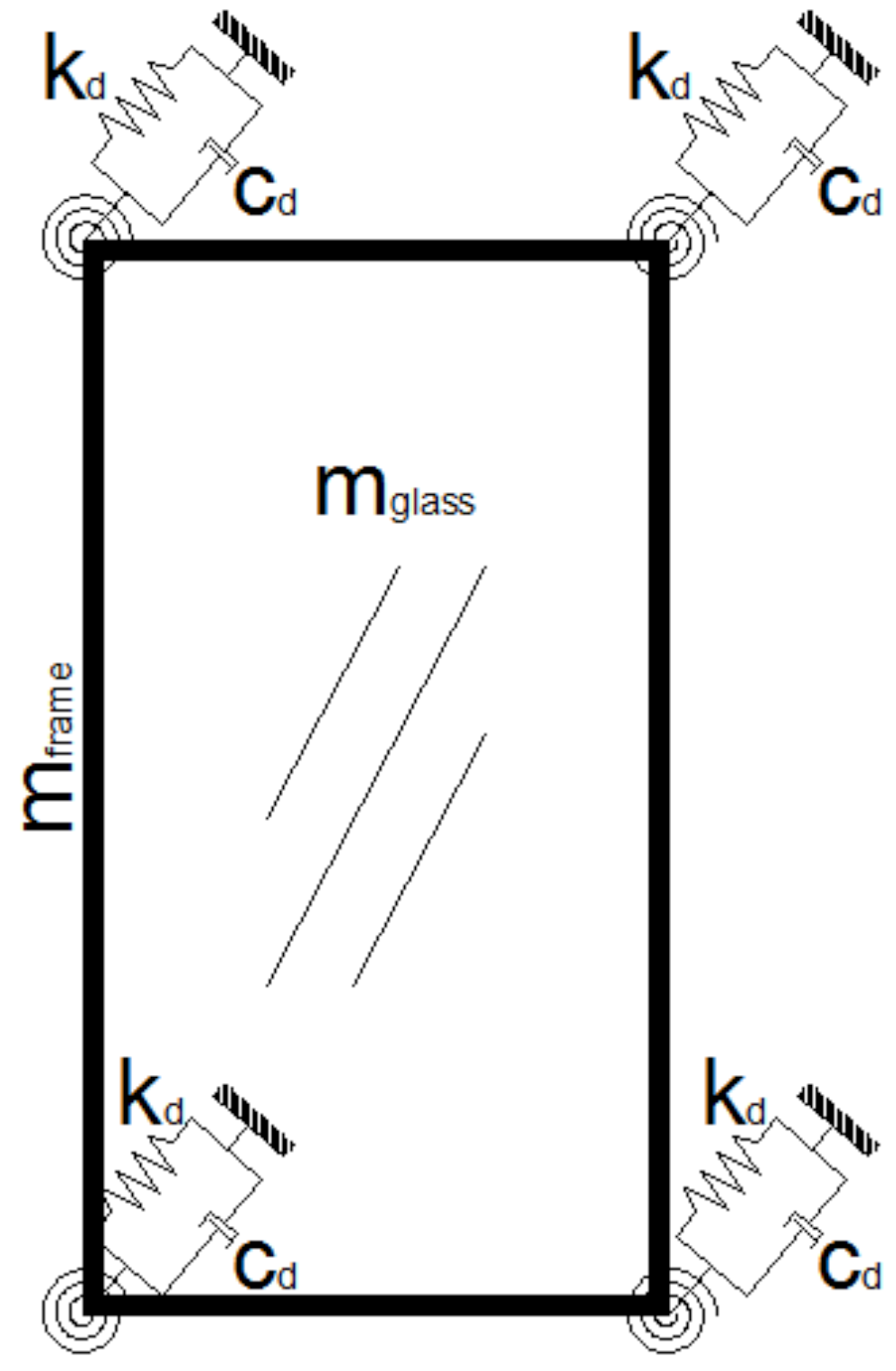
18]. Finally, the laminated glass panel was attached to the mullions by means of a bead of silicone sealant, described in the form of equivalent springs having normal stiffness
kn, shear stiffness
kv and rotational stiffness
kr [
18]. For these equivalent springs, one node was connected to an edge node of the panel, whereas the second node was connected to a corresponding node in the mesh of the frame (
Figure 6).
Also, damping effects were taken into account in performed simulations. A total damping ratio
ξtot = 1.75%, representative of aerolastic, PVB-interlayer and structural terms was taken into account, having estimated it accurately [
10,
19].
4.1.1. Material Properties
Material properties used in numerical simulations carried out with M01 and M02 FE-models are summarized in
Table 1.
Table 1.
Material properties for M01 and M02 FE-models.
Table 1.
Material properties for M01 and M02 FE-models.
| | Young’s Modulus[N/m2] | Poisson’s Ratio[-] | Density[kg/m3] | Behavior[-] |
|---|
| Glass | 7 × 10¹⁰ | 0.23 | 2490 | Linear elastic (M01); Brittle-elastic (M02) |
| PVB-film | 5 × 10⁸ | 0.49 | 1100 | Elastoplastic |
| Aluminum | 7 × 10¹⁰ | 0.30 | 2700 | Linear elastic (M01); Elastoplastic (M02) |
In M02, an appropriate model based on fracture mechanics was used [
20]. A correct representation of cracking and post-cracking behavior is fundamental to ensure the accuracy of numerical simulations. The
brittle cracking option of ABAQUS/Explicit is a smeared model that allows the cracking initiation in the behavior of brittle materials to be described. Primarily proposed for the simulation of cracking in concrete, the model can be applied to brittle materials in general, as for example, ceramics, rock or glass, which are dominated by tensile cracking and unimportant compressive failure [
16]. In it, a simple Rankine criterion is taken into account to detect crack initiation: once the maximum principal tensile stress exceeds the pre-established tensile strength
σR, the glass lite cracks. The crack surface is assumed to be orthogonal to the direction of the maximum tensile stress. Subsequent cracks can form, at the same integration point, only orthogonally to existing crack surface. The
brittle cracking numerical approach used does not track individual cracks in the brittle material, but the presence of cracks is taken into account in independent calculations at each integration point by the way in which cracks affect stress and stiffness at each material point. Cracking is irrecoverable, thus once opened, cracks are considered in computation for the rest of the simulation and their orientation is stored for subsequent calculations. However, no permanent strains associated with cracking are taken into account and cracks can close completely and reopen during analysis. The brittle failure model of ABAQUS/Explicit requires the implementation of two material properties: the tensile strength
σR , and the fracture energy
GfI, defined as the energy required to form a unit area of crack. Since blast loads represent a rare event in the lifetime of buildings, the characteristic tensile strength of glass is commonly assumed to give a 10% probability of breaking. In this work, in accordance with the suggestions of the Home Office Scientific Development Branch and the US Army Corps of Engineers, the tensile strength of annealed glass lites was assumed equal to
σR = 80 MPa [
21,
22]. In addition, based on numerical comparisons with experimental results proposed in the following section, a value
GfI = 100 J/m
2 of fracture energy was taken into account [
18].
The post-cracking behavior is taken into account in ABAQUS/Explicit through the brittle shear sub-option, which must be used in combination with the brittle cracking model. In it, the post-cracked stiffness is defined as a function of the opening strain across the crack and, in general, the cracked shear modulus Gcracked reduces as the cracks open. Since Gcracked is commonly defined as:
with G, the uncracked shear modulus, ρ(enmck) the shear retention factor:
And enmck the crack opening strain, the materials parameters p and enmck should be specified. Calibration of these post-cracking material parameters requires comparisons of numerical results with experimental data. In this work, based on calibrations partly discussed in the following section, the values p = 1 and enmck = 0.1 were assumed. In general, the cracking and post-cracking factors should be estimated with attention, since they represent an important aspect in simulations. The use of ABAQUS/Explicit brittle failure criterion, based on incorrect parameters, could result in incorrect numerical predictions. In addition, it should not be ignored that crack detection and accuracy of results directly depend on mesh size.
Concerning the other materials, an elastoplastic characteristic curve (
σy,PVB = 11 MPa) and a failure strain of 300% were taken into account to describe PVB-interlayer [
17]. Further experimental tests should be performed to highlight the unloading behavior of PVB films under high strain rate conditions. Nevertheless, if unloading is neglected, an elastoplastic material law represents a rational modeling assumption [
17]. Since explosions have a very short duration and the behavior of PVB-films strongly depends on loading time, a
glassy shear modulus
GPVB was considered, giving
EPVB = 500 MPa (
Table 1). Finally, in the M02 FE-model, the possible plasticization of mullions was taken into account, thus a characteristic yielding strength
σyk = 200 MPa and an ultimate tensile strength
σRk = 250 MPa were assumed.
4.1.2. Numerical Validation with Experimental Results
Preliminary numerical investigations were carried out to validate the modeling assumptions proposed in this work and to calibrate material parameters required in the brittle failure model used. As known, many factors can affect the response of a glass panel subjected to air blast loads, as for example the loading pattern, the boundary conditions, the glass age and type. Secondary effects, such ambient temperature and humidity or the adherence of the interlayer to glass surface, can result in an unpredictable response of glass panels to blast loads. Nevertheless, in some circumstances, numerical models can reproduce experiments with a good level of accuracy.
Firstly, bomb blast tests performed by Kranzer
et al. [
23] on a 3/1.5/3mm thick laminated glass panel were examined. Experimental data refer to a panel having dimensions 1.1 m × 0.9 m, subjected to 0.125 kg high explosive (HE) at a distance of 2 m [
23]. In ABAQUS, the design blast load was described in the form of a triangular pulse, obtained by introducing test blast parameters in the Friedlander equation. The laminated glass panel was connected along the four edges to a rigid steel frame, to reproduce test arrangement (3 m × 3 m concrete test wall and 1.1 m × 0.9 m steel frame [
23]). Equivalent springs were used at each boundary node, to simulate the effect of 4 mm thick and 50 mm wide rubber strips. In addition, the design blast load was introduced in the numerical model in the form of a uniformly distributed pressure applied to a 1.0 m wide and 0.8 m high loading surface [
23]. As proposed in
Figure 7 and
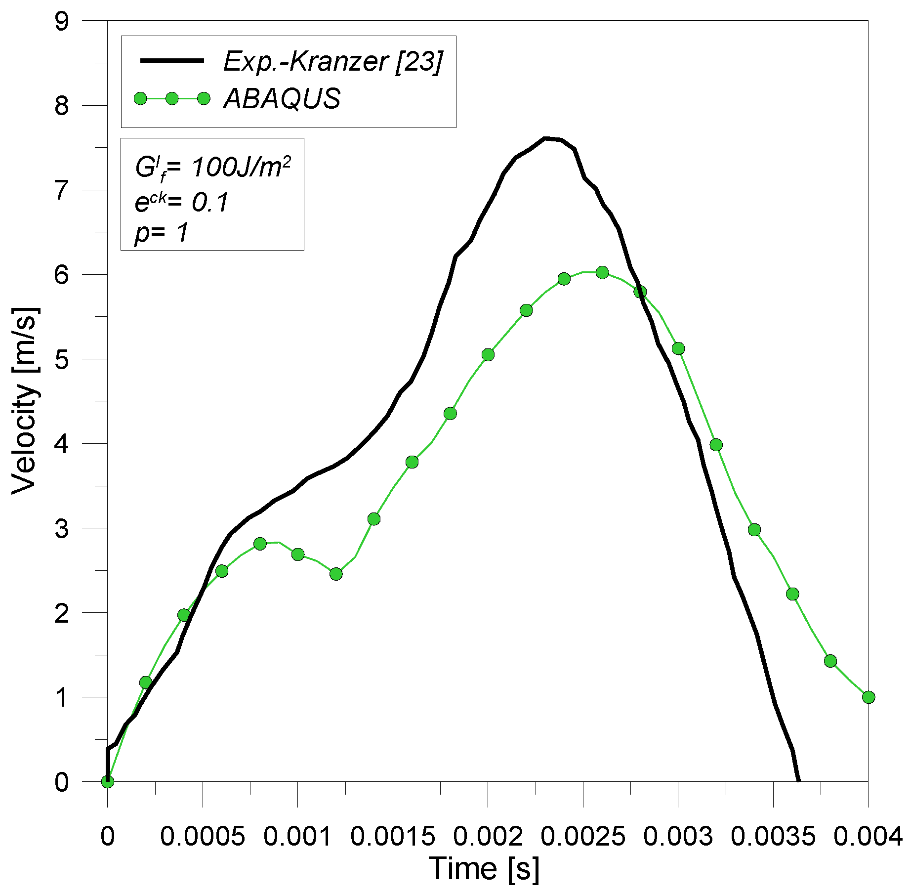
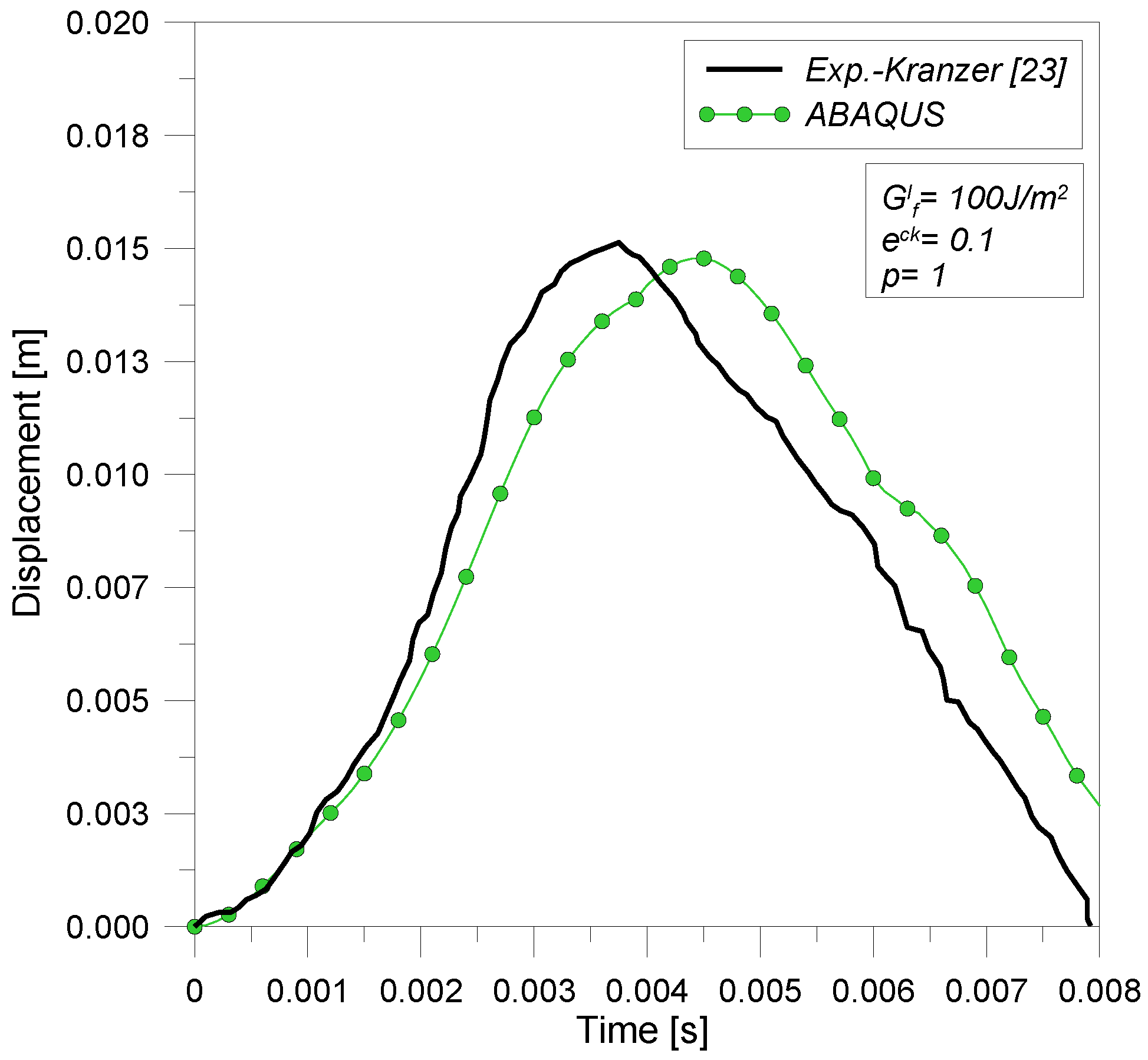
Figure 8, numerical and experimental results for maximum deflections and velocities of the glass panel are in good agreement. In Kranzer’s test, both the glass lites cracked, but the PVB-film did not fail. During numerical simulation, it was observed that both float glass plies cracked at about 0.0037 s, but no failure occurred in the PVB-film.
Results proposed in
Figure 7 and
Figure 8 were obtained assuming the following values for glass:
GfI = 100 J/m
2,
emaxck = 0.1 and
p = 1. Further parametric investigations highlighted that numerical results mainly depend on the values of
GfI, as highlighted in
Figure 9. Conversely, the adopted values for the parameters
emaxck and
p have negligible effects (in this work, simulations were performed, assuming the following values for
emaxck: 0.01, 0.001, 0.0001, and the values for
p: 1, 2, 3, 5). Consequently, post-cracking behavior seems not to influence results of performed numerical predictions. It is also interesting to notice that
GfI modifies only the maximum amplitude of deflections at the center of the panel, whereas both glass lites crack at about 0.0037 s.
Figure 7.
Deflection at the center of panel, as a function of time. Experimental (Kranzer, [
23]) and numerical (ABAQUS) results.
Figure 7.
Deflection at the center of panel, as a function of time. Experimental (Kranzer, [
23]) and numerical (ABAQUS) results.
Figure 8.
Velocity at the center of panel, as a function of time. Experimental (Kranzer, [
23]) and numerical (ABAQUS) results.
Figure 8.
Velocity at the center of panel, as a function of time. Experimental (Kranzer, [
23]) and numerical (ABAQUS) results.
Figure 9.
Maximum deflection at the center of panel, as a function of time (Kranzer, [
23] and ABAQUS). Parametric analyses (fracture energy G
If).
Figure 9.
Maximum deflection at the center of panel, as a function of time (Kranzer, [
23] and ABAQUS). Parametric analyses (fracture energy G
If).
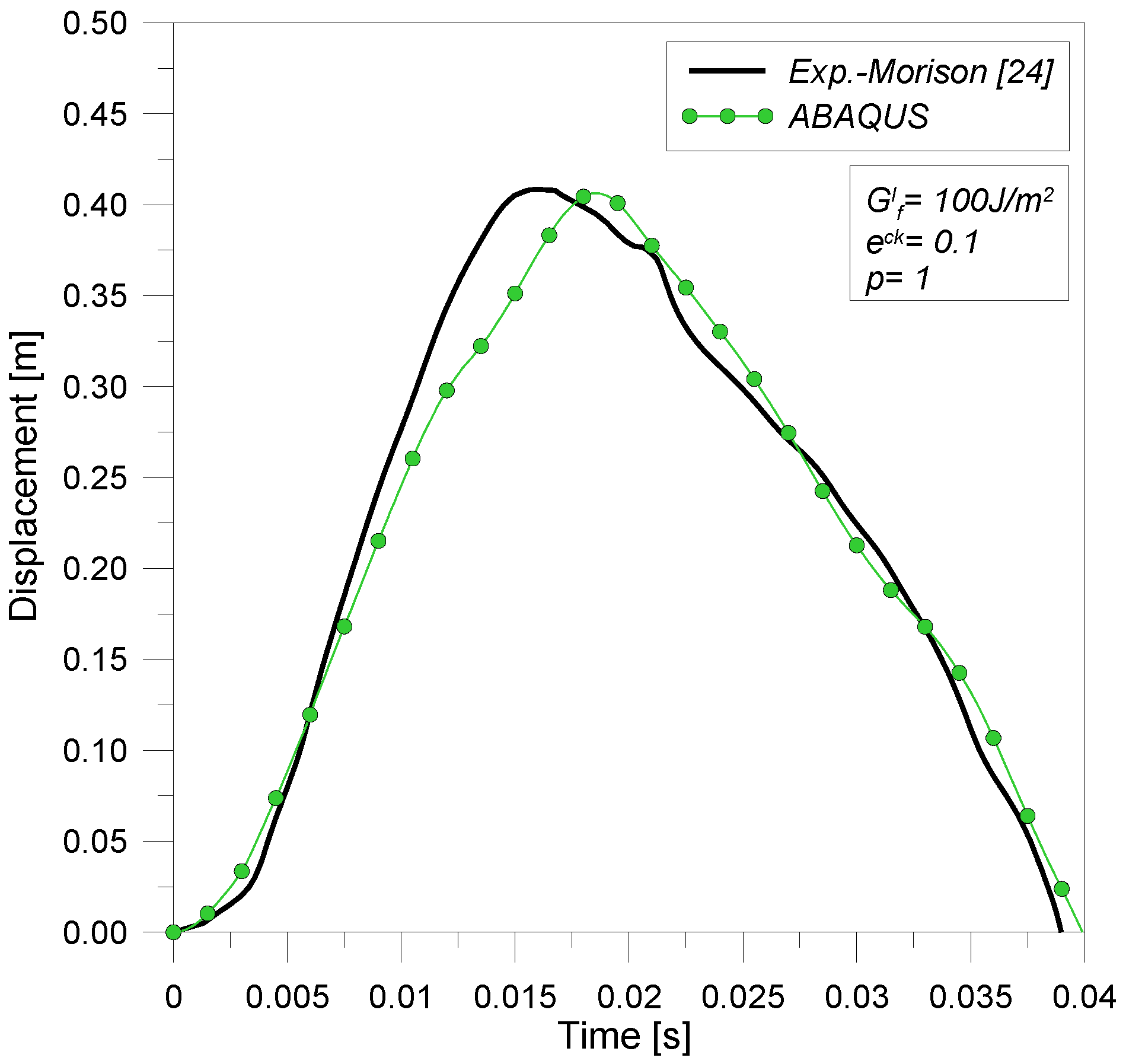
Based on these preliminary comparisons, further numerical validations were performed. Blast tests performed by Morison on 7.5 mm thick float laminated glass (1.25 m × 1.55 m) were taken into account [
24]. The explosive consisted in 60 kg of TNT (standoff distance 12 m). As previously done, test blast parameters were introduced in the Friedlander equation, and the time varying-pressure function obtained was used in ABAQUS to describe the amplitude of the distributed pressure applied to the glass surface. Composite shell elements were connected to a rigid steel frame through equivalent springs, able to reproduce the presence of a conventional bead of structural silicone sealant. Also, in this case, as shown in
Figure 10, numerical and experimental data agree.
Figure 10.
Deflection at the center of panel. Experimental (Morison, [
24]) and numerical (ABAQUS) results.
Figure 10.
Deflection at the center of panel. Experimental (Morison, [
24]) and numerical (ABAQUS) results.
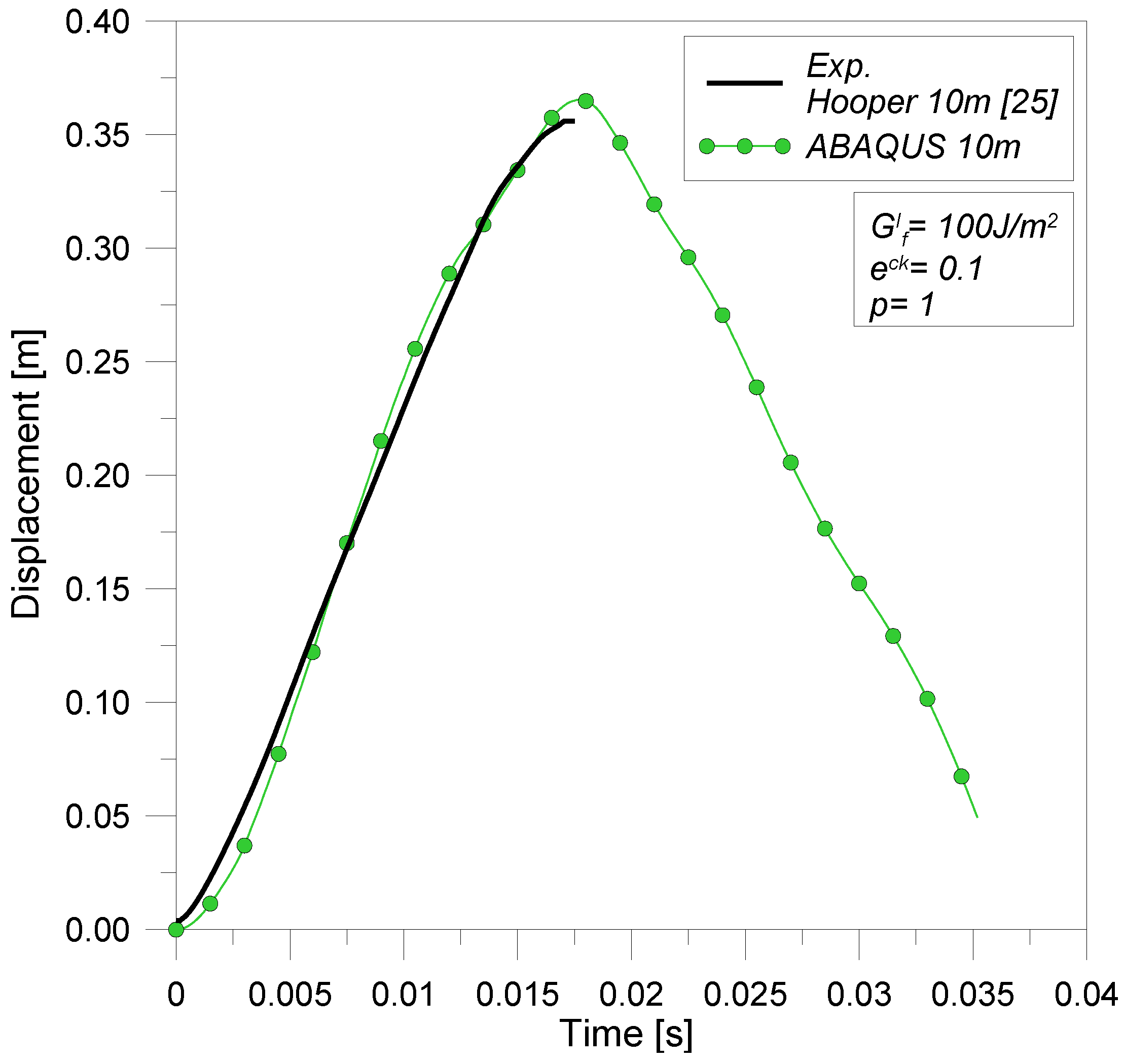
Figure 11.
Deflection at the center of pane. Experimental (Hooper, [
25]) and numerical (ABAQUS) results.
Figure 11.
Deflection at the center of pane. Experimental (Hooper, [
25]) and numerical (ABAQUS) results.
Finally, the comparison proposed in
Figure 11 refers to a test performed by Hooper on a 3/1.52/3 mm laminated glass panel (1.5 m × 1.2 m) subjected to 15 kg of C4-explosive at a distance of 10 m [
25]. In this simulation, the glass panel was connected by means of a 6 mm thick and 20 mm wide silicone joint (equivalent springs) to a rigid frame. Results proposed in
Figure 12 highlight that deflections obtained from test are in good agreement with numerical predictions.
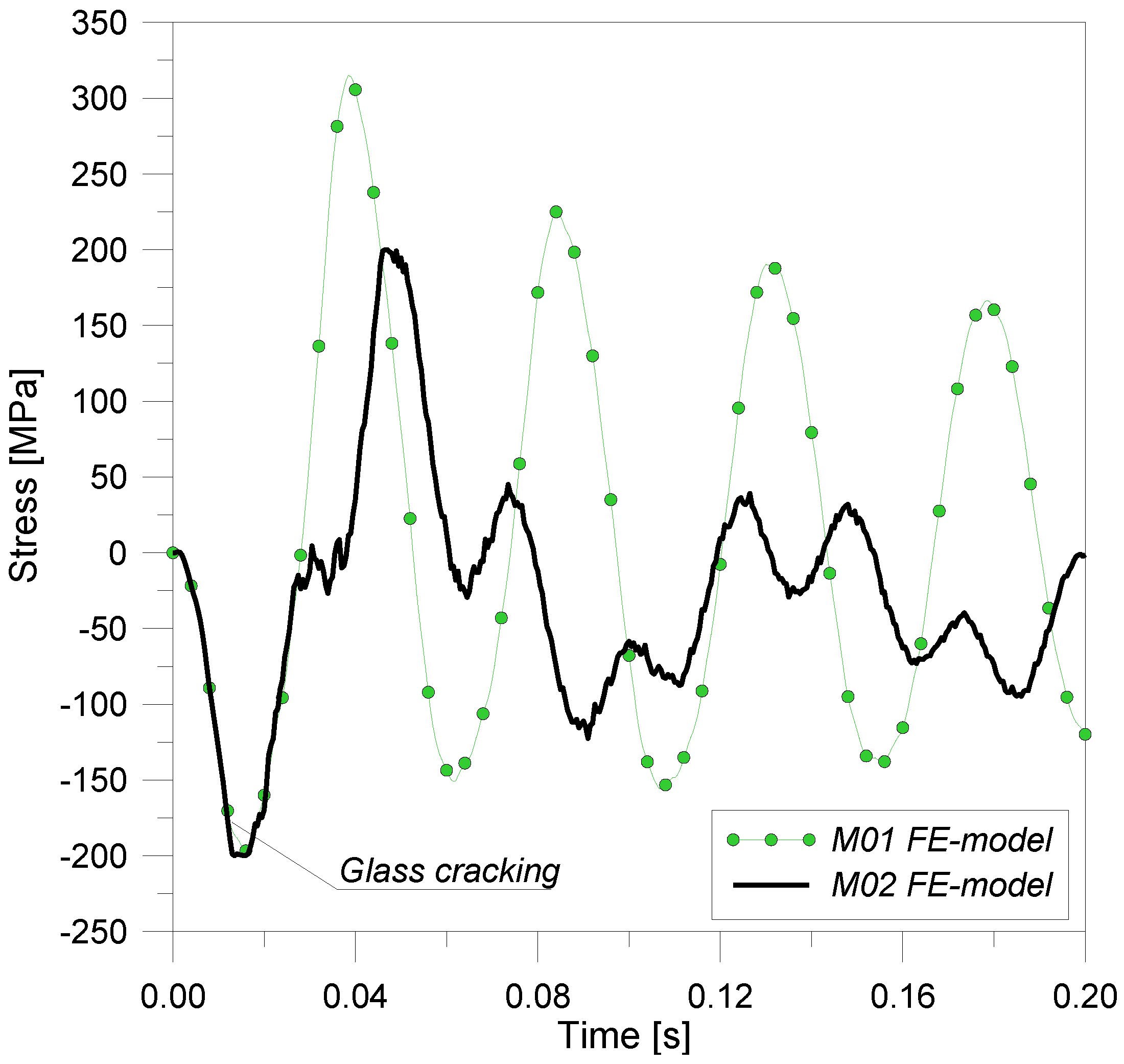
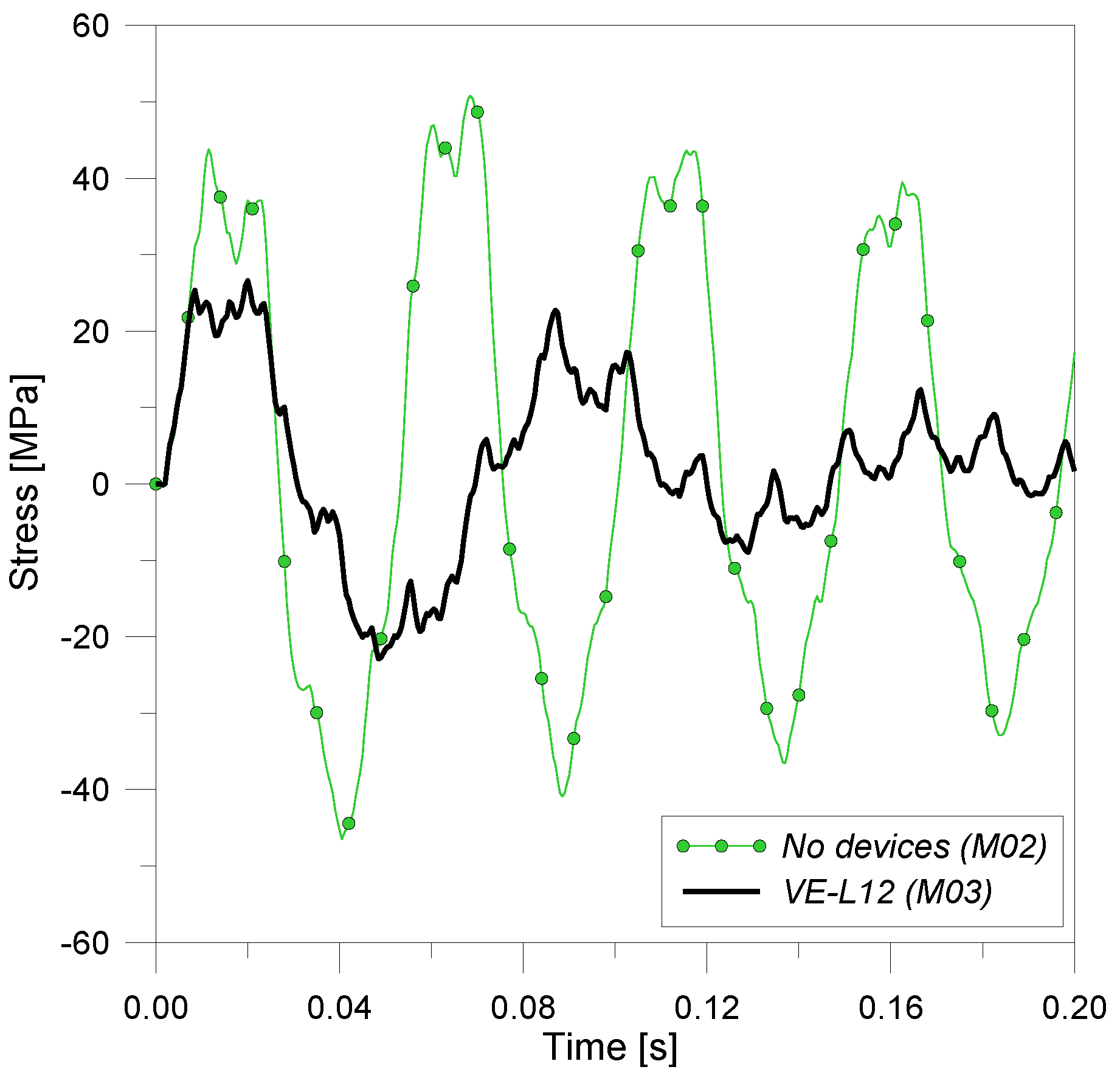
Figure 12.
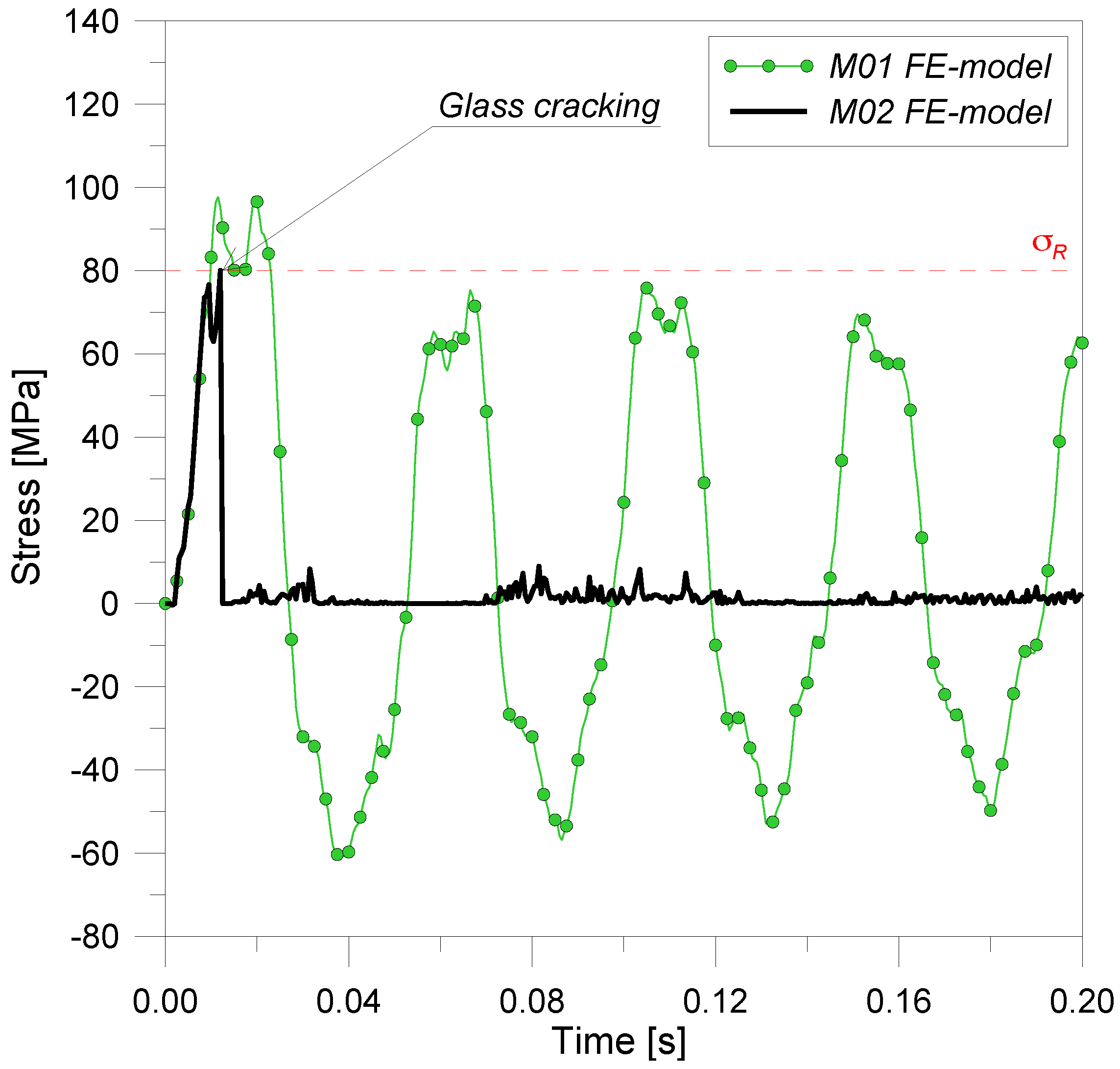
Comparison of maximum tensile stress at the center of panel (inner glass lite).
Figure 12.
Comparison of maximum tensile stress at the center of panel (inner glass lite).
4.1.3. Preliminary Numerical Analyses–Glass Cracking (M01 and M02 FE-Models)
Having checked the modeling assumptions, the behavioral trends of the elastic curtain wall attached to rigid steel brackets underwent a preliminary investigation (M01 FE-model). A modal analysis was performed, by taking into account geometric nonlinearity. The predicted fundamental period of vibration resulted equal to T1M01 = 0.049 s.
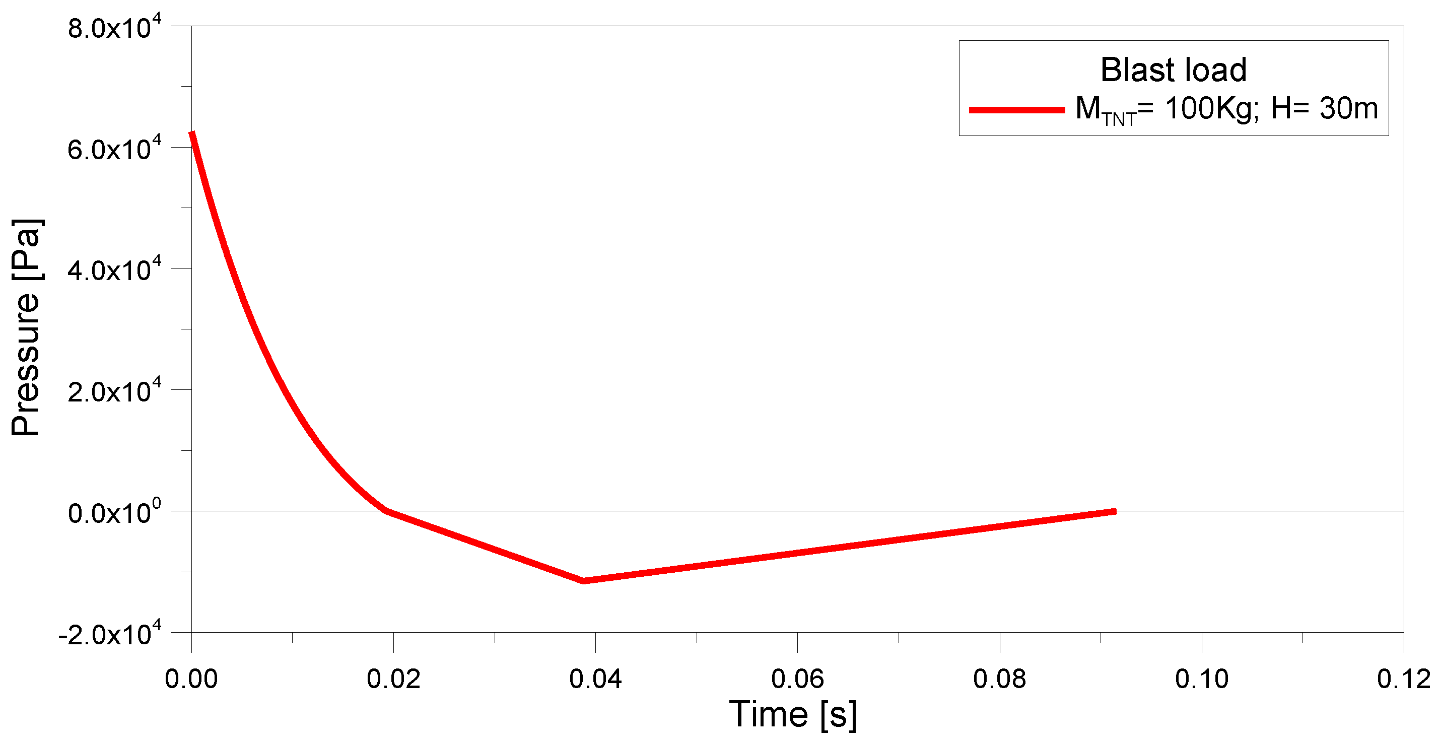
Subsequently, incremental nonlinear dynamic analyses were carried out on M01 and M02 FE-models, to highlight the effects of glass cracking. These analyses had a total duration of 0.2 s and maximum time step equal to 0.0005 s. The pre-established Level D blast wave was introduced in the form of a uniformly distributed, impulsive load
qblastD representative of the positive and negative phases of a high-level blast loading (
Figure 1). At the end of these dynamic explicit procedures, the mean time increment that resulted was 0.0000053 s.
As noticed by Dharani
et al. [
7] and Weggel and Zapata [
10], in a simply supported panel subjected to a uniformly distributed load, the maximum tensile stresses occur at the center of the glass lite. For this purpose,
Figure 12 shows the maximum tensile stresses at the center of a single glass lite (the inner one not directly exposed to blast loading). It is possible to observe that if glass linear-elastically behaves (M01), a maximum tensile stress
σmax,glassM01 = 98 MPa occurs at
t = 0.0115 s. The fundamental period of the elastic system is approximately
T1M01 ![Buildings 02 00359 i021]()
(
Figure 12), thus it is in agreement with modal analysis prediction.
A similar value
T1M01 suggests that the glazing system is very stiff. This effect depends on the linear-elastic behavior of materials and on the over-dimensioned components of the curtain wall, as well as on the rigid support provided by conventional steel brackets. However, it should not be ignored that the design of blast-resisting curtain walls strongly differs from the design of glazing systems subjected to ordinary loads, and the use of very thick components is unavoidable. In contrast, if a brittle-cracking model and elastoplastic behavior are used for glass and aluminum (M02), the ultimate tensile strength
σmax,glassM02 = σR = 80 MPa occurs in the inner glass lite (the one not directly exposed to blast loading) at
t = 0.0120 s, as proposed in
Figure 12. When cracks open and propagate, the maximum stresses rapidly modify their distribution on the surface of the panel.
In addition, the performed analyses showed that maximum principal stresses have equal magnitude in the two glass sheets, at each instant in time. As a result, as usually happens in layered shell models subjected to air blast waves, the second glass lite (the one directly exposed to blast loading) fails at the same instant of the first one [
17].
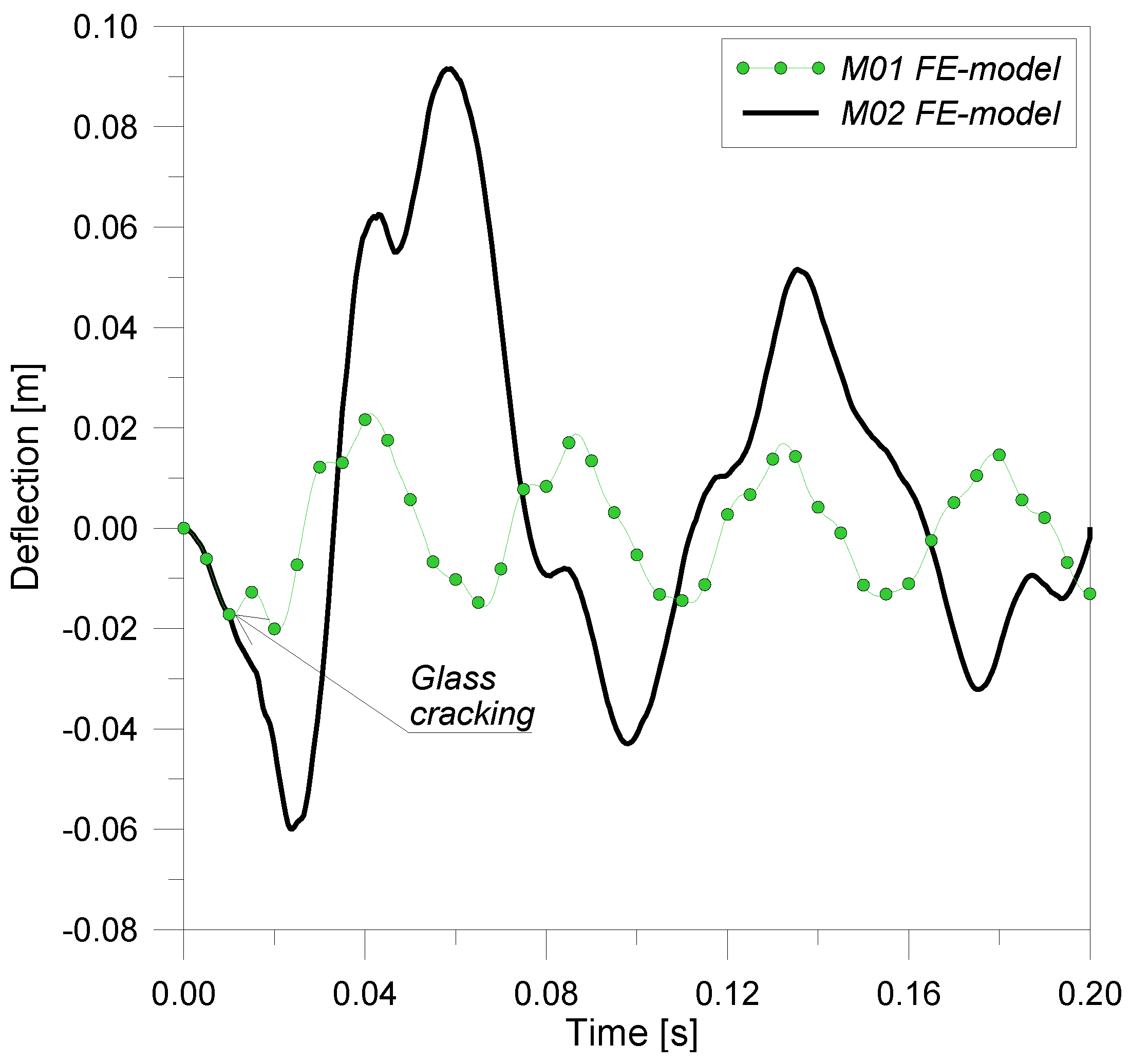
After the failure of glass lites, the interlayer plastically reacts and the dynamic response of the glazing system strongly modifies. However, in the simulations performed, it was noticeable that in this specific example, the PVB-film plasticizes but does not fail. In
Figure 13, the deflection time series at the center of the panel is depicted. As shown, after the breaking of glass, the deflection of the panel abruptly increases (
umax,glassM01 = 0.023 m,
umax,glassM02 = 0.092 m), as well as the fundamental period of the system (
![Buildings 02 00359 i022]()
).
Figure 13.
Comparison of deflection at the center of panel (inner glass lite).
Figure 13.
Comparison of deflection at the center of panel (inner glass lite).
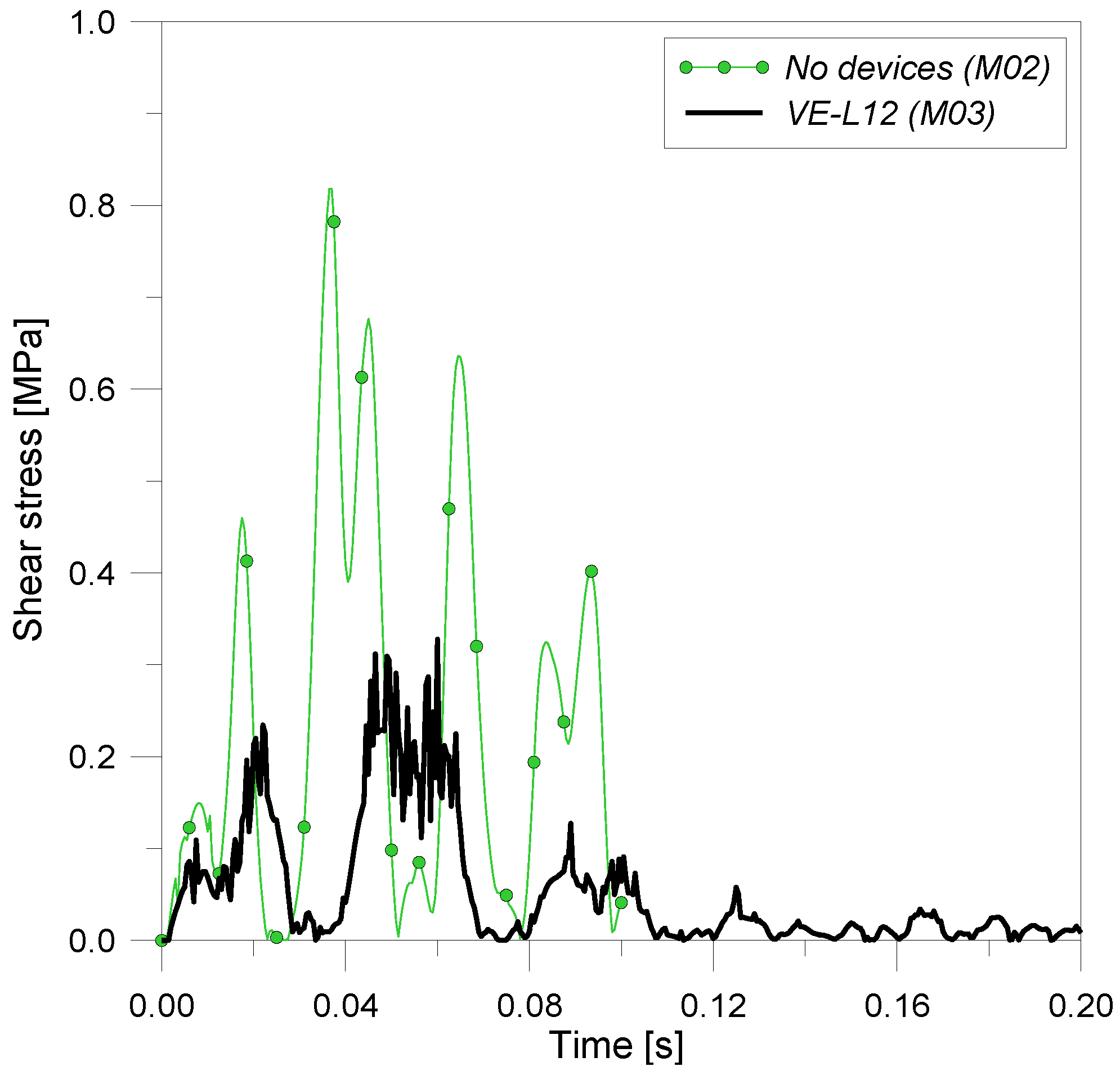
Figure 14.
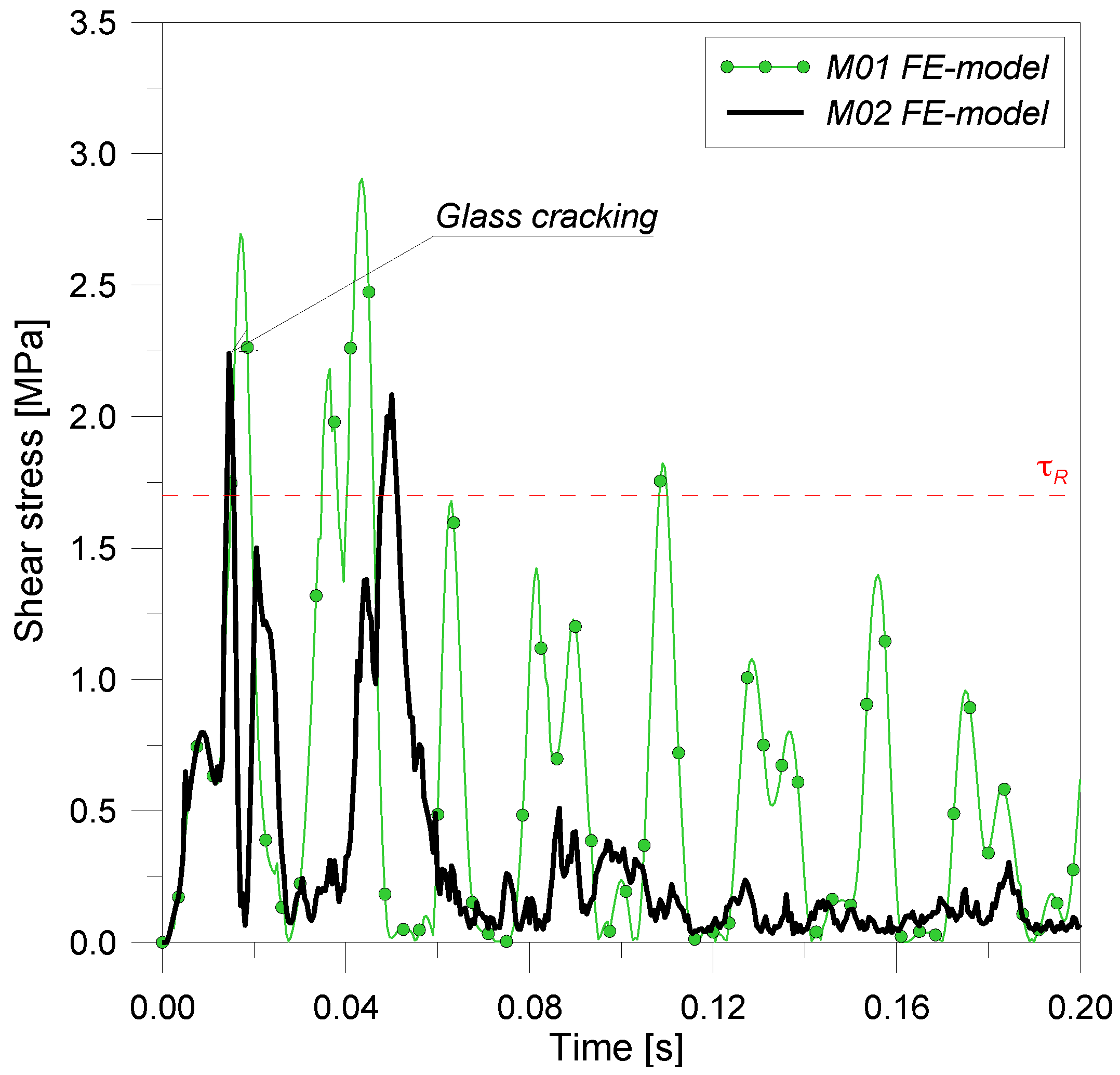
Comparison of maximum envelope of shear stresses in the bead of structural silicone.
Figure 14.
Comparison of maximum envelope of shear stresses in the bead of structural silicone.
It is evident that, depending on the level of explosion, glass lites can crack or not. In any case, the bead of silicone sealant represents a critical component in similar glass curtain walls. When the explosion occurs, elevated forces are transferred from the glass panel to the silicone joint, in the form of shear stresses acting in the plane of the glass. These shear stresses, due to the impulsive nature of air blast load and to large displacements reached by glass lites, increase abruptly and significantly and directly transfer to mullions in the form of transverse loads. At the same time, the negative phase of blast pressure could involve elevated tensile stresses in the structural silicone. Consequently, its failure should be avoided to prevent the detachment of the glass panel from the frame and to preserve the integrity of the cladding wall. For this purpose,
Figure 14 shows a comparison between the maximum envelopes of shear stress in the silicone joint for M01 and M02 FE-models (maximum envelopes along the frame). As depicted in the figure, the breaking of glass sheets and the plasticization of screw mullions only partly cut down the maximum stresses (
τmax,siliconeM01 = 2.90 MPa,
τmax,siliconeM02 = 2.24 MPa). Similar values of stress are unacceptable, since high-speed tests performed by Hautekeer
et al. [
26] resulted in average shear strength
τR = 1.7 MPa for structural silicone sealant subjected to air blast loading.
Performed simulations showed that the tubular frame is also strongly affected by blast loading, thus elevated reactions are directly transferred to the supporting brackets and to the structural backup. Specifically, if the aluminum frame does not behave linear-elastically and glass lites break (M02), the maximum axial stresses occurring in mullions decrease from
σmax,mullionM01 = 315 MPa to
σmax,mullionM02 = 200 MPa (
Figure 15). A detailed investigation of M02 results highlighted that aluminum mullions yield at about 0.0115bs, thus immediately before glass cracking. Frequently, yielding of aluminum mullions has an important role in the dynamic response of similar glazing system, since it could allow a reduction of the maximum stresses achieved in the main structural components and to dissipate part of the incoming energy due to blast. Nevertheless, parametric numerical analyses summarized in the following sections highlighted that in the presence of VE devices, the damping contribution of yielding in mullions is negligible if compared to the dissipative capabilities of the proposed viscoleastic mechanism, and often the aluminum frame does not plasticize. Nevertheless, to ensure the accuracy of results, numerical simulations should always be performed by taking into account an elastoplastic characteristic law for the aluminum frame. Finally, another aspect that should be taken into account in the design of a similar blast resistant glazing system consists of the elevated reactions transmitted from the supporting brackets to the structural backup. In this work, if glass sheets break, each bracket should be able to resist to a maximum reaction, equal to
RmaxM02 =47 kN (
RmaxM01 = 57 kN for the M01 elastic system).
Figure 15.
Comparison of maximum axial stress in vertical mullions.
Figure 15.
Comparison of maximum axial stress in vertical mullions.
As a result, it is possible to make a preliminary assertion that the glass cracking and the mullion plasticization evidently modifies the distribution of stresses and displacements in the main components of similar curtain walls, thus appropriate numerical models (especially for glass) should be used to predict their behavioral trends due to high-level dynamic loads. Particular attention should be also dedicated to the possible failure of the bead of structural silicone, since the integrity of the curtain wall would be compromised. As proposed in the following section, the detachment of the glass panel from the bearing frame could be prevented by introducing appropriate VE devices in the conventional curtain wall, able to provide additional dissipative/deformability capabilities. In addition, the behavioral trends of the glazing system could drastically improve.
4.2. Curtain Wall with Viscoelastic Brackets (M03 FE-Model)
Numerical simulations performed on M01 and M02 FE-models highlighted that since the conventional brackets provide a rigid translational restraint to the frame corners, no obvious dissipative mechanisms could be developed in the dynamic response of the curtain wall. As a result, in M01, only the estimated total damping, ξtot = 1.75%. contributes to a reduction of the effects of the design explosion. In M02, both total damping, ξtot , and additional dissipative terms due to glass cracking and to the plasticization of PVB and mullions could be taken into account. Nevertheless, maximum stresses reached in the curtain wall components are still elevated, as highlighted in previous sections.
Based on these assumptions, dissipative devices were introduced to replace the conventional rigid brackets. The M03 FE-model consists of the M02 curtain wall equipped with viscoelastic devices, modeled in the form of equivalent springs attached at the four corners of aluminum mullions. Additional nonlinear dynamic analyses were performed to investigate the possible structural benefits of VE devices. Since the parameters able to define the characteristic behavior of each viscoelastic device are
kd and
cd (Equation (1)), incremental dynamic analyses were performed, assuming them to be a series of values estimated in a sufficiently wide range. A squared shape and a thickness 0.01 m ≤
h ≤ 0.03 m were assumed for the viscoelastic layer. The most significant examples are summarized in
Table 2 (
h = 0.02 m).
Table 2.
Mechanical properties of VE devices (h = 0.02 m).
Table 2.
Mechanical properties of VE devices (h = 0.02 m).
| VE Device | L [m] | kd [N/m] | kmullion/kd [-] | cd (Equation (1)) [N/m] | T* [s] | T1M03 (ABAQUS) [s] |
|---|
| VE-L20 | 0.20 | 2,000,000 | ≈0.4 | 7124 | 0.039 | 0.060 |
| VE-L16 | 0.16 | 1,280,000 | ≈0.6 | 5690 | 0.049 | 0.067 |
| VE-L12 | 0.12 | 720,000 | ≈1.0 | 4274 | 0.065 | 0.079 |
| VE-L08 | 0.08 | 320,000 | ≈2.2 | 2850 | 0.098 | 0.107 |
| VE-L04 | 0.04 | 80,000 | ≈9.0 | 1425 | 0.196 | 0.200 |
In the same table, a series of fundamental periods
T* = 2
π/
ω are also proposed for the curtain wall equipped by devices, with
ω given by Equation (4). These values are compared with numerical periods
T1M03 obtained by a series of modal analyses performed in ABAQUS on the equipped curtain walls (M03 FE-model). It is interesting to notice that VE devices strongly modify the fundamental period of vibration of the conventional glazing system (
T1M03 >
T1M01 = 0.049 s). As it would be expected, the lower the stiffness
kd , the higher is the period
T1M03. The values of
T1M03, summarized in
Table 2, do not take into account the effects of glass cracking or mullion plasticization, however they provide interesting information to be taken into account in a first design of the proposed VE devices.
In addition, it is possible to notice a good agreement between the analytical periods T* and the corresponding numerical values T1M03, especially in the presence of VE devices that are not extremely rigid (mean ratio between analytical and numerical fundamental periods: 0.82).
The main results of dynamic incremental analyses are reported in
Table 3 and
Table 4. Depending on the mechanical properties of VE devices, parametric analyses highlighted that glass cracking can occur (or not) in the studied curtain wall. Specifically, a detailed analysis of numerical results showed that glass lites crack only if the proposed VE devices are extremely rigid, and the distribution of maximum tensile stresses in glass lites results similar to
Figure 12 (M02 FE-model). In contrast, due to the additional deformability introduced in the conventional curtain wall, appropriately designed VE devices can prevent the cracking of glass sheets (
Table 3). Main structural benefits of VE devices can be observed in mullions and in the bead of silicone, as well as in glass lites, in the form of a noticeable reduction of maximum stresses (
Table 3).
Table 3.
Numerical results of parametric analyses (ABAQUS). Glass, silicone and VE devices.
Table 3.
Numerical results of parametric analyses (ABAQUS). Glass, silicone and VE devices.
| VE Device | Glass Deflection umax,glass [m] | Glass Cracking; Crack Opening [s]/Stress σmax,glass [MPa] | Silicone Shear Stress τmax,silicone [MPa] | Device Displacement smax [m] | Device Sliding γmax = smax/h [-] |
|---|
| No device (M02) | 0.0915 | Yes; 0.0120 | 2.240 | - | - |
| VE-L20 | 0.0504 | Yes; 0.0190 | 2.784 | 0.0202 | 1.01 |
| VE-L16 | 0.0171 | No/74.78 | 1.663 | 0.0291 | 1.45 |
| VE-L12 | 0.0146 | No/64.35 | 1.610 | 0.0386 | 1.93 |
| VE-L08 | 0.0112 | No/54.61 | 1.472 | 0.0606 | 3.03 |
| VE-L04 | 0.0076 | No/53.12 | 1.184 | 0.0851 | 4.23 |
Table 4.
Numerical results of parametric analyses (ABAQUS). Mullions and brackets.
Table 4.
Numerical results of parametric analyses (ABAQUS). Mullions and brackets.
| VE Device | Mullion Deflection umax,mullion [m] | Mullion Stress σmax,mullion; Yielding [MPa] | Bracket Reaction Rmax [kN] |
|---|
| No device (M02) | 0.0442 | 200.00; Yes | 47.23 |
| VE-L20 | 0.0366 | 200.00; Yes | 45.46 |
| VE-L16 | 0.0334 | 200.00; Yes | 40.63 |
| VE-L12 | 0.0292 | 173.13; No | 33.02 |
| VE-L08 | 0.0232 | 118.51; No | 23.26 |
| VE-L04 | 0.0160 | 54.92; No | 11.77 |
In general, similar effects directly depend on the characteristics of the VE devices used. To maximize the effectiveness of the proposed mechanism, it should not be ignored that in their dimensioning, it is fundamental to assume an adequate value for the elastic stiffness
kd. VE devices defined in
Table 2,
Table 3,
Table 4 as VE-L20 and VE-L04, in this context, represent two limit conditions. The first one (VE-L20) represents an extremely rigid device, not able to undergo large relative displacements when a high-level explosion occurs (
smaxM03 = 0.0202 m,
Table 3), whereas the second one (VE-L04) is associated to an excessive sliding (
smaxM03 = 0.0851 m,
Table 3), consequently is not able to adequately resist the design blast loading. The choice of the optimal VE mechanism depends on the behavioral trends of the devices in the presence of high-level explosions. To avoid the breaking of the viscoelastic layer, their maximum sliding
γmax =
smax/
h should be limited to
![Buildings 02 00359 i026]()
. At the same time, it should not be neglected that the increase of
kd involves higher relative displacements and tensile stresses in glass lites, silicone and mullions, thus higher reactions transmitted to the structural backup (
Table 4).
In these hypotheses, the system of devices defined in
Table 2,
Table 3,
Table 4 as VE-L12 seems to be the most appropriate solution for the studied example (
γmax = 1.93,
Table 3). As a result, the dynamic response of the studied curtain wall strongly improves due to the introduction of devices.
Firstly, it is important to notice that in the presence of VE-L12 devices, glass lites do not crack (
σmax,glassM03 = 64.35 MPa,
Table 4). As a result, maximum axial stresses in mullions are also strongly cut down and no yielding occurs in the aluminum frame (
σmax,glassM03 = 173 MPa,
Table 4).
In
Figure 16, the deflection at the center of the laminated glass panel is shown, for M02 FE-model and for the curtain wall equipped with VE-L12 devices (M03 FE-model). Clearly, the devices reduce their maximum deflection, and significant differences can be observed by comparing the proposed curves (
umax,glassM02 = 0.0915 m and
umax,glassM03 = 0.0146 m,
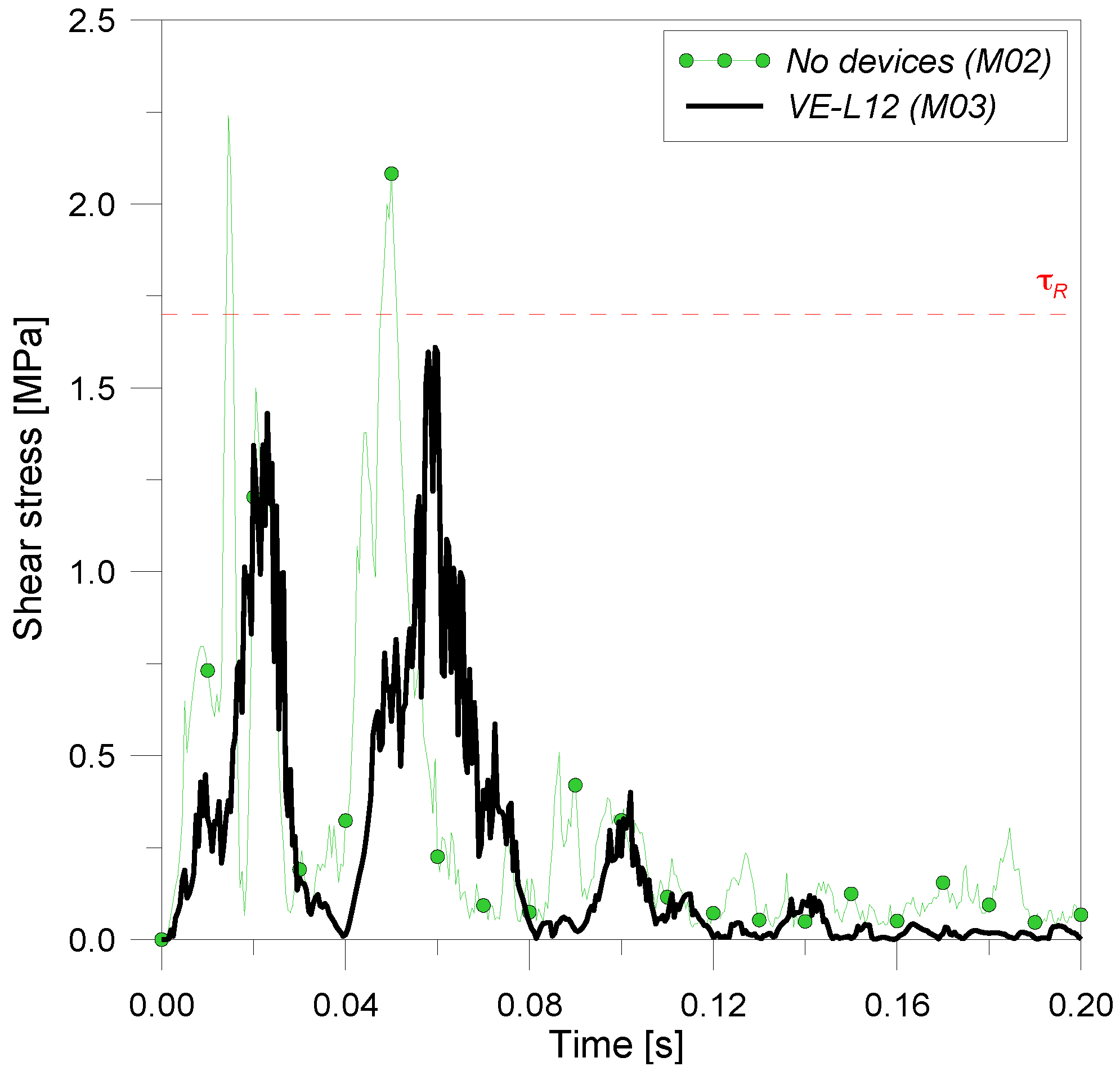
Figure 16). Similarly, the maximum shear stresses occurring in the bead of silicone appear noticeably reduced. In this specific circumstance, obvious differences can be noticed by comparing numerical results (
τmax,siliconeM02 = 2.24 MPa and
τmax,siliconeM03 = 1.61 MPa,
Figure 17). Consequently, for the shear resistance considered in this work, it is possible to assert that opportunely-designed VE devices avoid the failure of the bead of silicone, hence preserving the integrity of the curtain wall. This finding represents an important aspect to be taken into account in the analysis of similar glazing systems.
Figure 16.
Comparison of deflection at the center of panel.
Figure 16.
Comparison of deflection at the center of panel.
Figure 17.
Comparison of maximum envelope of shear stress in the bead of silicone.
Figure 17.
Comparison of maximum envelope of shear stress in the bead of silicone.
The deflection of vertical mullions strongly also decreases in the curtain wall equipped with VE devices, due both to the dissipative contribution of the VE mechanism and the additional elasticity they provide (
![Buildings 02 00359 i029]()
of the structural span and
![Buildings 02 00359 i030]()
,
Table 4). In this manner, vertical mullions do not plasticize in the presence of high-level explosions, and maximum axial stresses are noticeably reduced (
σmax,mullionM02 = 200 MPa and
σmax,mullionM03 = 173 MPa). As a result, maximum reactions transferred to each bracket strongly decrease (
RmaxM02 = 47.23 kN and
RmaxM03 = 33.02 kN).
In general, simulations highlighted that the less stiff the VE devices, the less the axial stresses in mullions and the reactions in brackets (
Table 4).
In the presence of appropriately designed VE devices, the design explosion has less of an effect on the main components of the equipped glazing system. As summarized in
Table 3 and
Table 4, the additional elasticity/damping contribution of VE devices reduces maximum deflections and stresses in them. In this context, it should also be noticed that the global damping coefficient,
ξ , of the glazing systems examined, approximately estimated on the basis of the logarithmic decrement of displacements proposed in
Figure 15 [
27], results in
![Buildings 02 00359 i031]()
for the equipped curtain wall (M03 FE-model) and
![Buildings 02 00359 i032]()
for the rigid supported glazing system (M02 FE-model). Thus, as it would be expected,
ξM02 is slightly higher than the total damping considered in the modeling of the curtain wall (
ξtot = 1.75%), due to glass cracking as well as to mullion plasticization. At the same time, it is interesting to notice that
ξM03 is approximately equal to the medium damping coefficient previously calculated for the studied glazing system by means of the simplified analytical procedure (
ξ = 30%, Equation (5)). These results represent only a first estimation of the maximum damping effects of VE devices on similar curtain walls, but they could constitute a starting point in the design of the proposed mechanism.
4.3. Energy Considerations
As is already known, an abrupt release of energy typically characterizes impulsive loading, such as in the case of explosions. Such energy is transferred to the curtain wall and to the structural backup in the form of:
– elastic energy ΔEelastic, defined as a function of the elastic deformation of the main components of the system. ΔEelastic is an energy contribution stored by the structure in the first instants of motion, and subsequently released;
– kinetic energy ΔEkinetic: depending on the velocity acquired by the oscillating glazing system, is the first energy term which impinges on the curtain wall and which is stored by the main components;
– plastic energy ΔEplastic, representative of plasticization of PVB-interlayer and aluminum frame;
– damage energy ΔEdamage, dissipated when glass cracks;
– viscous energy ΔEviscous, representative of the dissipative properties of the curtain wall (aerolastic damping) and the VE devices (if present).
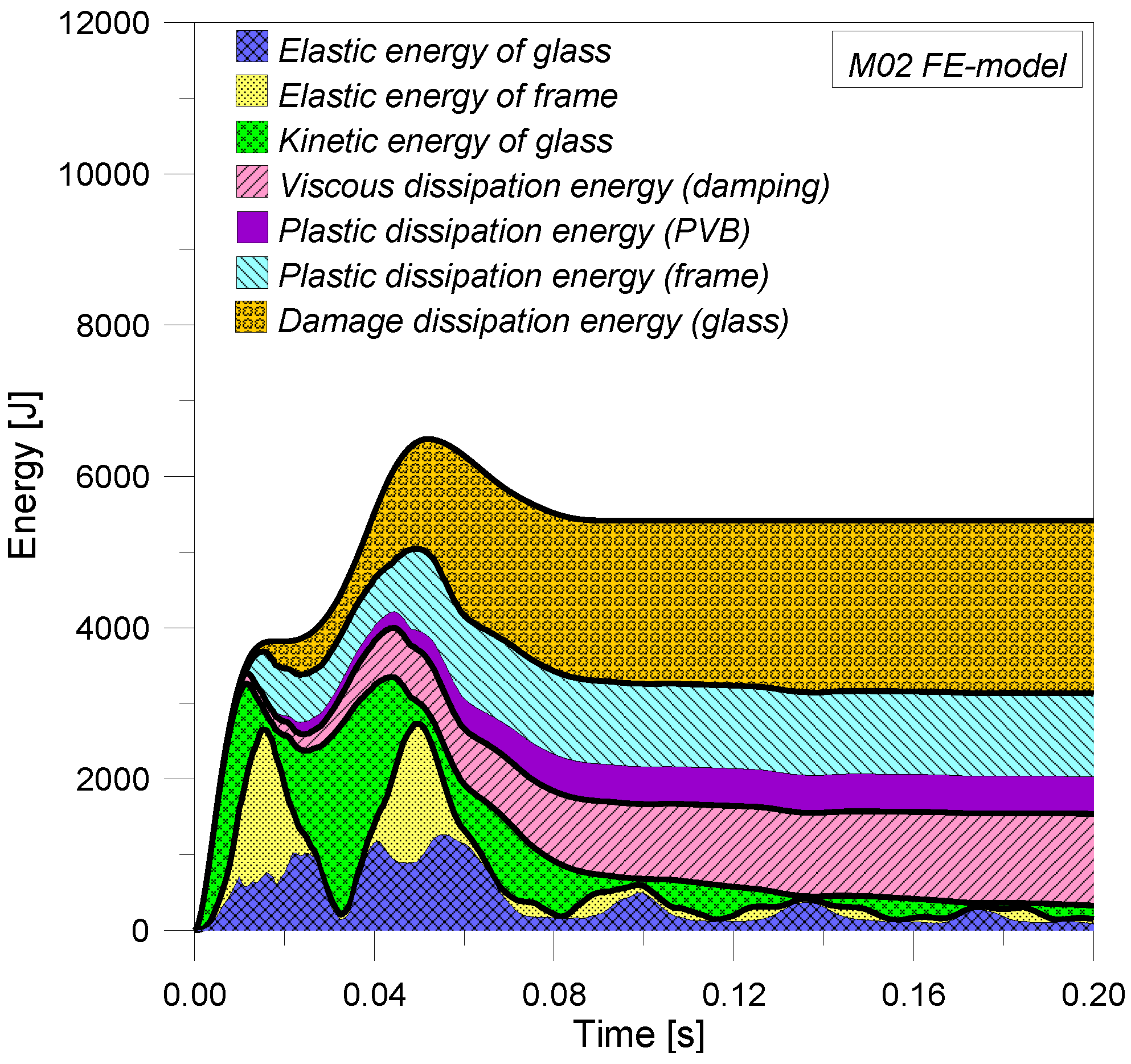
In
Figure 18 and
Figure 19, the energy balance of a conventional curtain wall and a curtain wall equipped by VE-L12 devices are proposed. If VE devices (
Figure 18) do not equip the curtain wall, the system is able to minimally dissipate the incoming energy due to an explosion, since its damping capabilities, as previously noticed, are limited. As a result, viscous energy is negligible (
![Buildings 02 00359 i033]()
), whereas the main dissipation is associated with the cracking of glass (Δ
Edamage) and to plastic energy of the PVB-interlayer and aluminum frame (Δ
Eplastic).
Figure 18.
Energy balance for the curtain wall not equipped with VE devices.
Figure 18.
Energy balance for the curtain wall not equipped with VE devices.
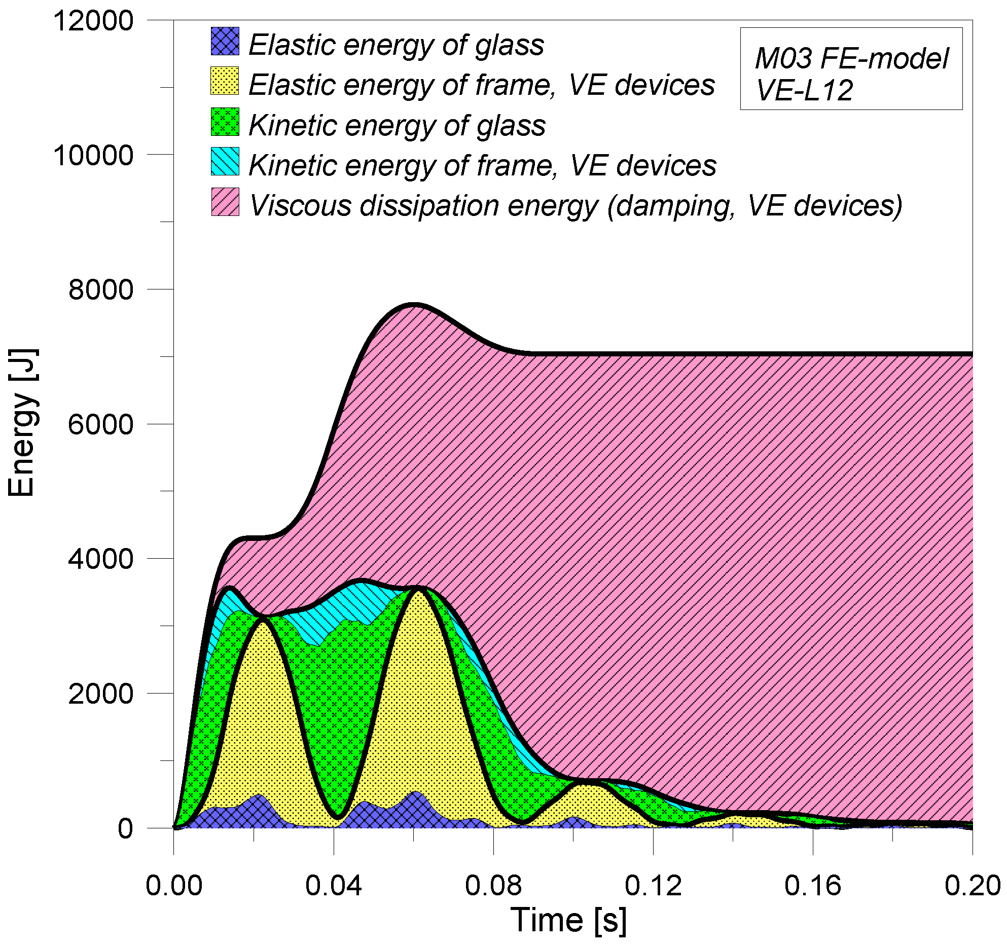
Figure 19.
Energy balance for the curtain wall equipped with VE devices.
Figure 19.
Energy balance for the curtain wall equipped with VE devices.
Contrarily, if appropriate VE devices are used, viscous energy becomes the prevalent term in the energy balance of the curtain wall and, as would be expected, additional dissipative phenomena are null (in the presence of VE-L12 devices, glass lites do not crack and mullions do not yield, thus
![Buildings 02 00359 i036]()
,
Figure 19). At the same time, due to the mitigation role of VE devices, the elastic and kinetic energies stored by glass panes and mullions drastically decrease. As highlighted in
Figure 19, in particular, the first effect that can be observed in the energy balance of the curtain wall equipped by VE devices is a strong reduction of strain energy stored by the glass panel and by the aluminum frame. As would be expected, VE devices store the main term of strain energy due to design blast load, and this finding confirms the efficacy of the proposed mechanism. Additional damping capabilities of VE devices manifest only in subsequent instants, improving the potentiality of the viscoelastic system and preserving the main components of the curtain wall from serious damage.
4.4. Effects of Viscoelastic Devices with Low-Level Air Blast Loading (M03 FE-Model)
Finally, additional simulations were performed to investigate the capability of VE-L12 devices in the presence of low-level blast loads, to generalize the effectiveness of the new proposed system. A Level B-blast wave pressure characterized by a static overpressure peak
prB = 30.4 kPa was taken into account (M
TNT = 25 Kg, H = 30 m [
13]). In this work, the level-B blast loading represents the load that the curtain wall would sustain before damage occurs (glass cracking, silicone failure, mullion plasticization,
etc.). Performed simulations showed that although glass sheets do not crack in both the circumstances, VE-L12 devices strongly reduce maximum stresses in glass panes (
Figure 20,
σmaxM03 /
σmaxM02 = 0.52) and silicone (
Figure 21,
τmaxM03/
τmaxM02 = 0.40). Similar results highlight at best the potentiality of the proposed system. Concerning the vertical mullions, performed simulations showed that maximum axial stresses are equal to
σmax,mullionM03 = 75 MPa for M03 FE-model (
σmaxM03/
σmaxM02 = 0.66, if results of M03 FE-model are compared to maximum stresses achieved in the presence of rigid brackets). Therefore, reactions transmitted to the structural backup also obviously reduce (
RmaxM03 = 14.65 kN, with
RmaxM03/
RmaxM02 = 0.73).
Figure 20.
Comparison of maximum tensile stress at the center of panel.
Figure 20.
Comparison of maximum tensile stress at the center of panel.
Figure 21.
Comparison of maximum envelope of shear stress in the bead of silicone.
Figure 21.
Comparison of maximum envelope of shear stress in the bead of silicone.
In conclusion, the results obtained allow an extension of the effectiveness of the proposed devices to a generic level of air blast loading, as well as to ordinary dynamic loads, obtaining important structural and energy benefits for the curtain wall as well as for the structural backup.
Certainly, the results presented depend on the variability of the design blast loading and the mechanical parameters characterizing the dynamic behavior of the proposed VE mechanism. The response of the viscoelastic system subjected to impulsive high-level loads, for example, undoubtedly requires further investigation. Clearly, experimental tests should be performed to check the validity and accuracy of numerical simulations, as well as to reduce possible uncertainties in the design of a similar mechanism. At the same time, it cannot be ignored that no analytical models can be used to predict the behavioral trends of similar curtain walls equipped with VE devices. Nevertheless, the proposed simulations could represent a starting point for advanced stages in the design of similar blast-resistant curtain walls.


 (Figure 12), thus it is in agreement with modal analysis prediction.
 ).
).


 . At the same time, it should not be neglected that the increase of kd involves higher relative displacements and tensile stresses in glass lites, silicone and mullions, thus higher reactions transmitted to the structural backup (Table 4).
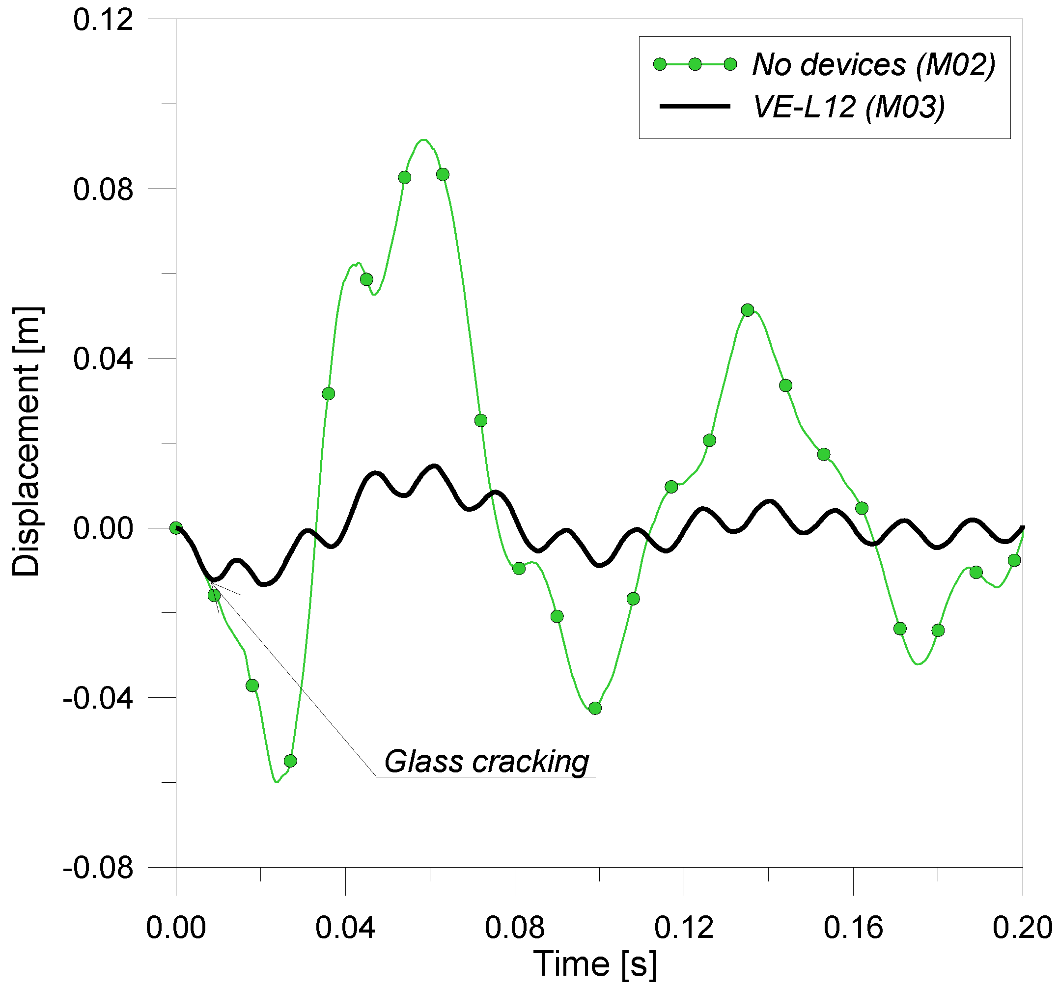
 of the structural span and
  , Table 4). In this manner, vertical mullions do not plasticize in the presence of high-level explosions, and maximum axial stresses are noticeably reduced (σmax,mullionM02 = 200 MPa and σmax,mullionM03 = 173 MPa). As a result, maximum reactions transferred to each bracket strongly decrease (RmaxM02 = 47.23 kN and RmaxM03 = 33.02 kN).
 for the equipped curtain wall (M03 FE-model) and
  for the rigid supported glazing system (M02 FE-model). Thus, as it would be expected, ξM02 is slightly higher than the total damping considered in the modeling of the curtain wall (ξtot = 1.75%), due to glass cracking as well as to mullion plasticization. At the same time, it is interesting to notice that ξM03 is approximately equal to the medium damping coefficient previously calculated for the studied glazing system by means of the simplified analytical procedure (ξ = 30%, Equation (5)). These results represent only a first estimation of the maximum damping effects of VE devices on similar curtain walls, but they could constitute a starting point in the design of the proposed mechanism.
 ), whereas the main dissipation is associated with the cracking of glass (ΔEdamage) and to plastic energy of the PVB-interlayer and aluminum frame (ΔEplastic).
 , Figure 19). At the same time, due to the mitigation role of VE devices, the elastic and kinetic energies stored by glass panes and mullions drastically decrease. As highlighted in Figure 19, in particular, the first effect that can be observed in the energy balance of the curtain wall equipped by VE devices is a strong reduction of strain energy stored by the glass panel and by the aluminum frame. As would be expected, VE devices store the main term of strain energy due to design blast load, and this finding confirms the efficacy of the proposed mechanism. Additional damping capabilities of VE devices manifest only in subsequent instants, improving the potentiality of the viscoelastic system and preserving the main components of the curtain wall from serious damage.
