Multi-Directional Seismic Assessment of Historical Masonry Buildings by Means of Macro-Element Modelling: Application to a Building Damaged during the L’Aquila Earthquake (Italy)

 , and
, and
Abstract
:1. Introduction
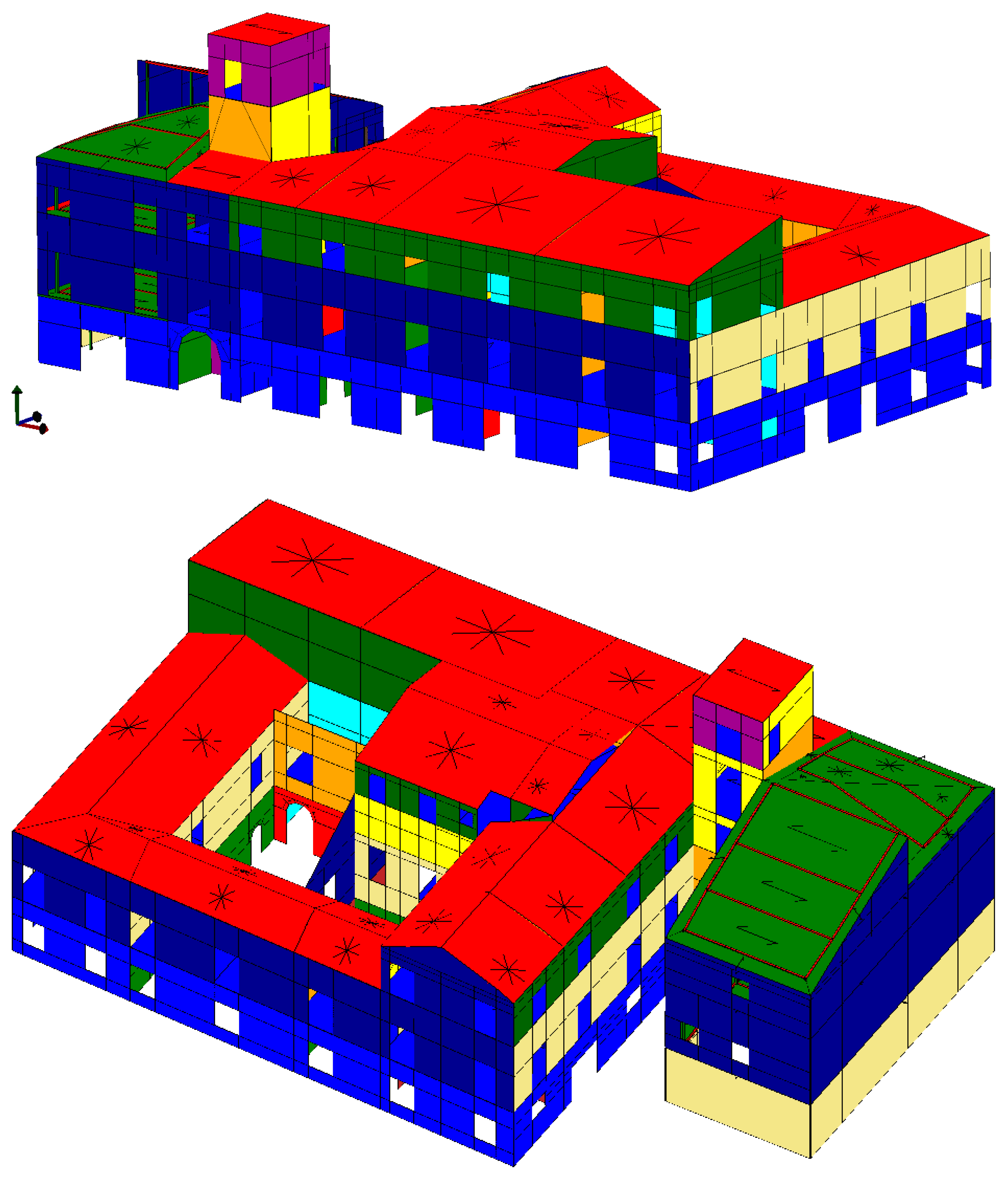
2. The Case Study: The Gualtieri Building in L’Aquila
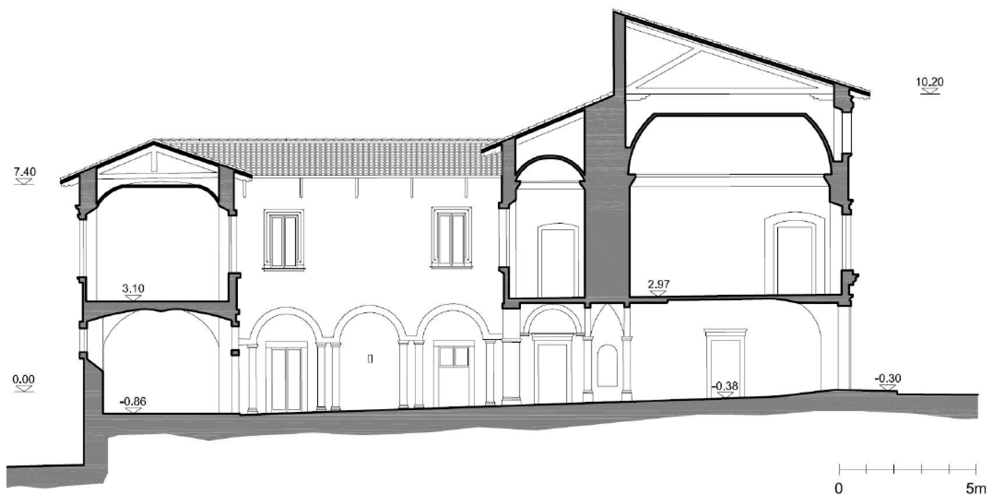
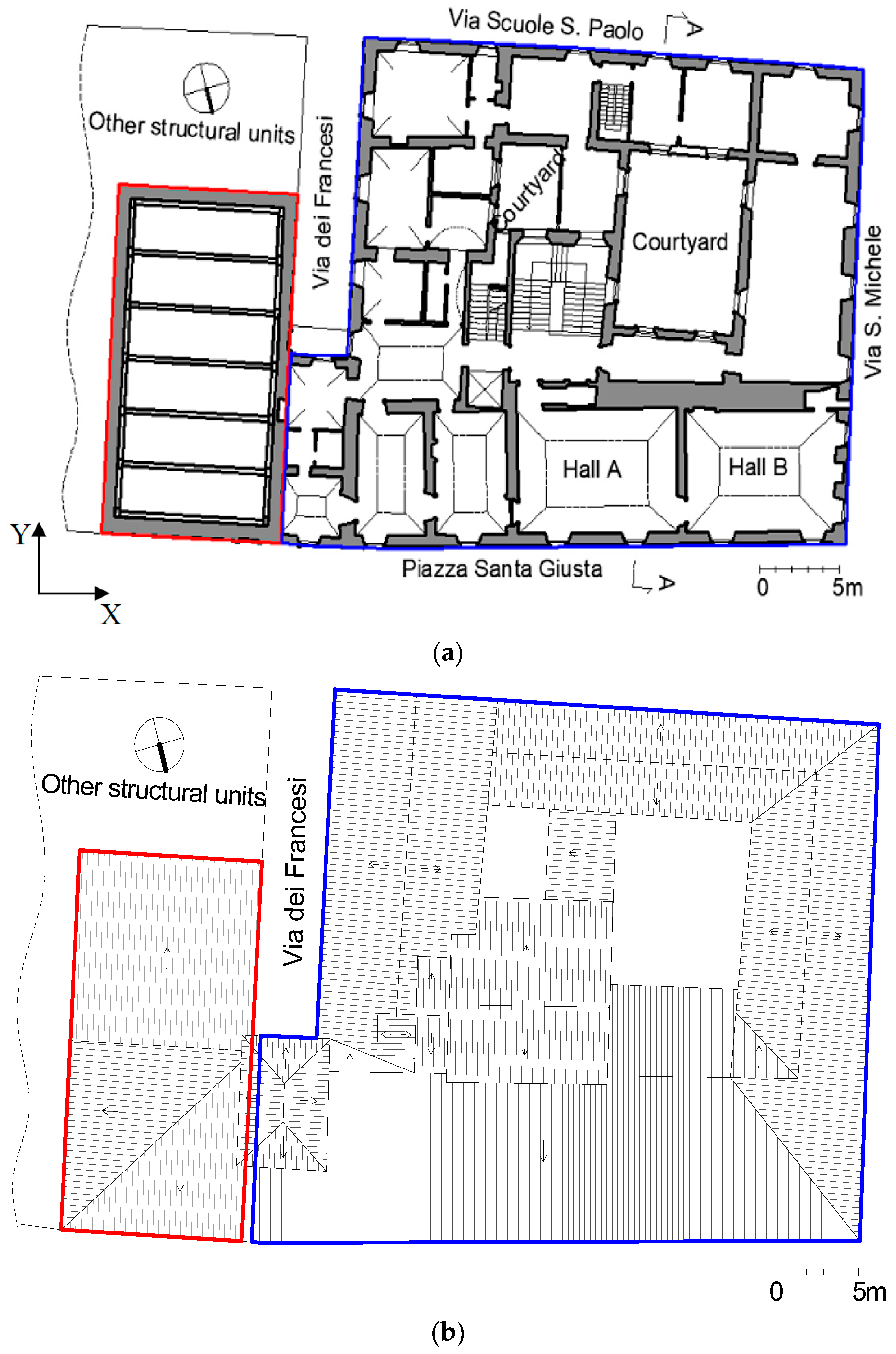
2.1. Historical and Architectural Description
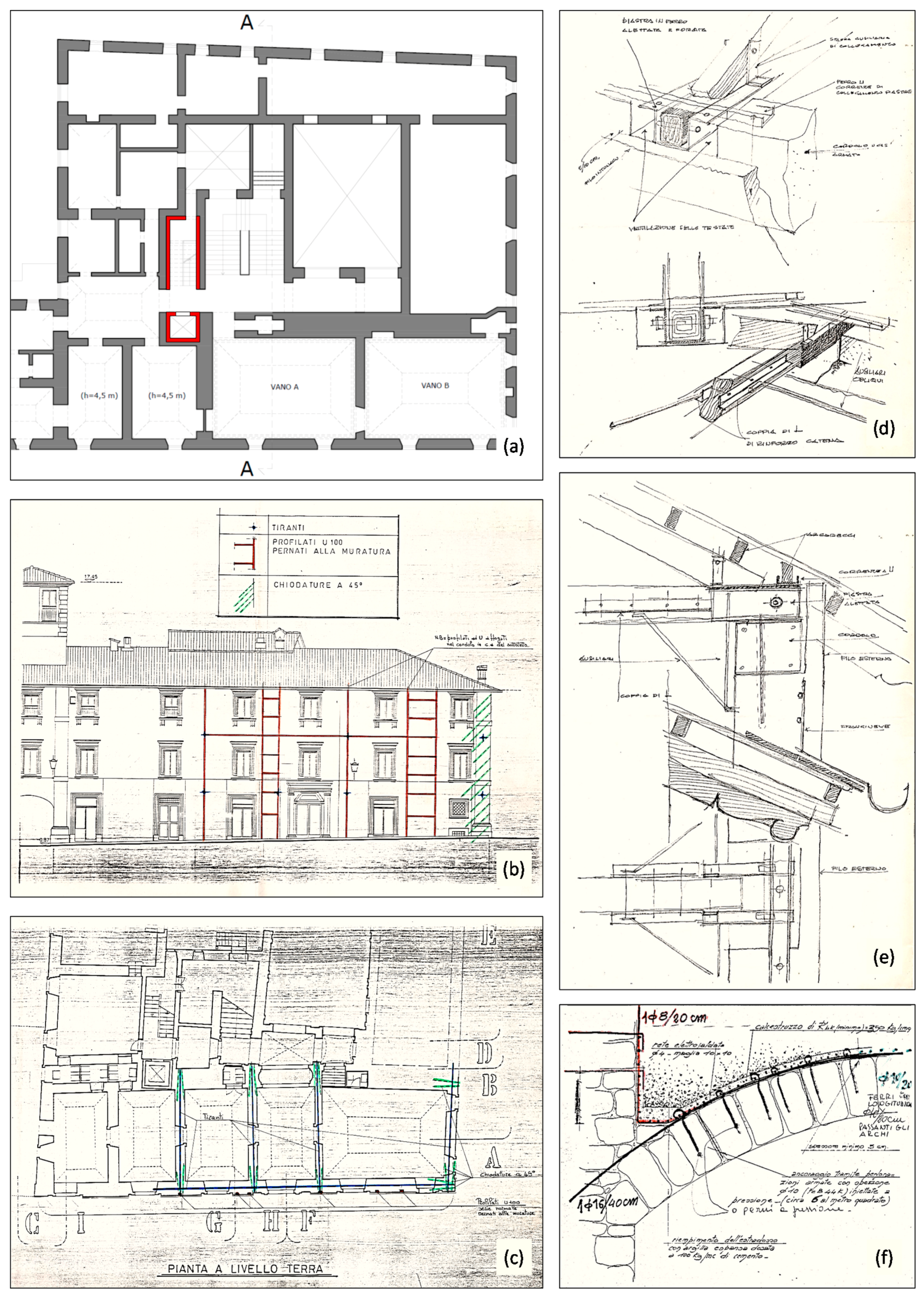
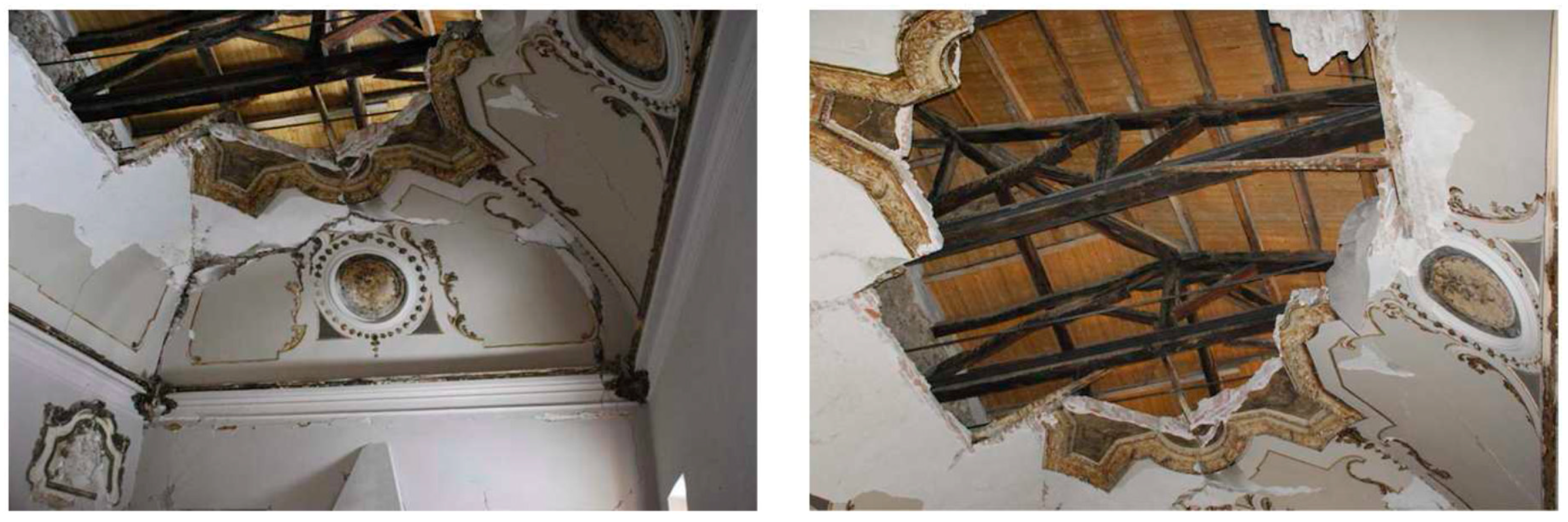
2.2. Past Strengthening Interventions of Structural Retrofitting
- -
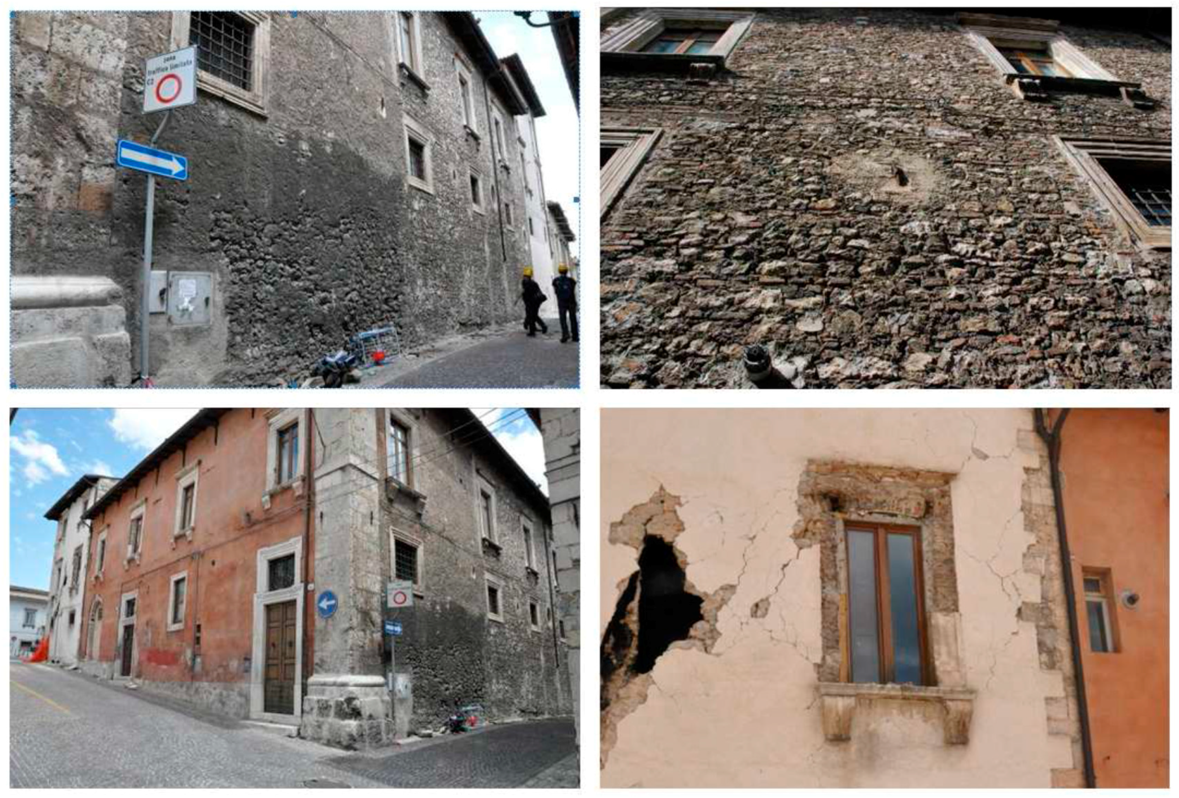
- plastered masonry on the northern and western prospects, and on Via dei Francesi, made of calcareous ashlars with some bricks; on the southern front two different masonry typologies with visible leaf can be observed: the first is partially plastered and made of irregular calcareous ashlars, while the second has also some levelings with bricks (Figure 5);
- -
- corner with ashlars (visible and not perfectly smoothed), with lime mortar (Figure 5);
- -
- widest doors at the first level are surmounted by monolithic lintels, the smallest ones and the windows of the upper levels are surmounted by lintels made of several ashlars and brick arches (Figure 5); and
- -
- vaults of the two halls A and B are made of bricks ordered according to a knife arrangement, with some wooden ribs.
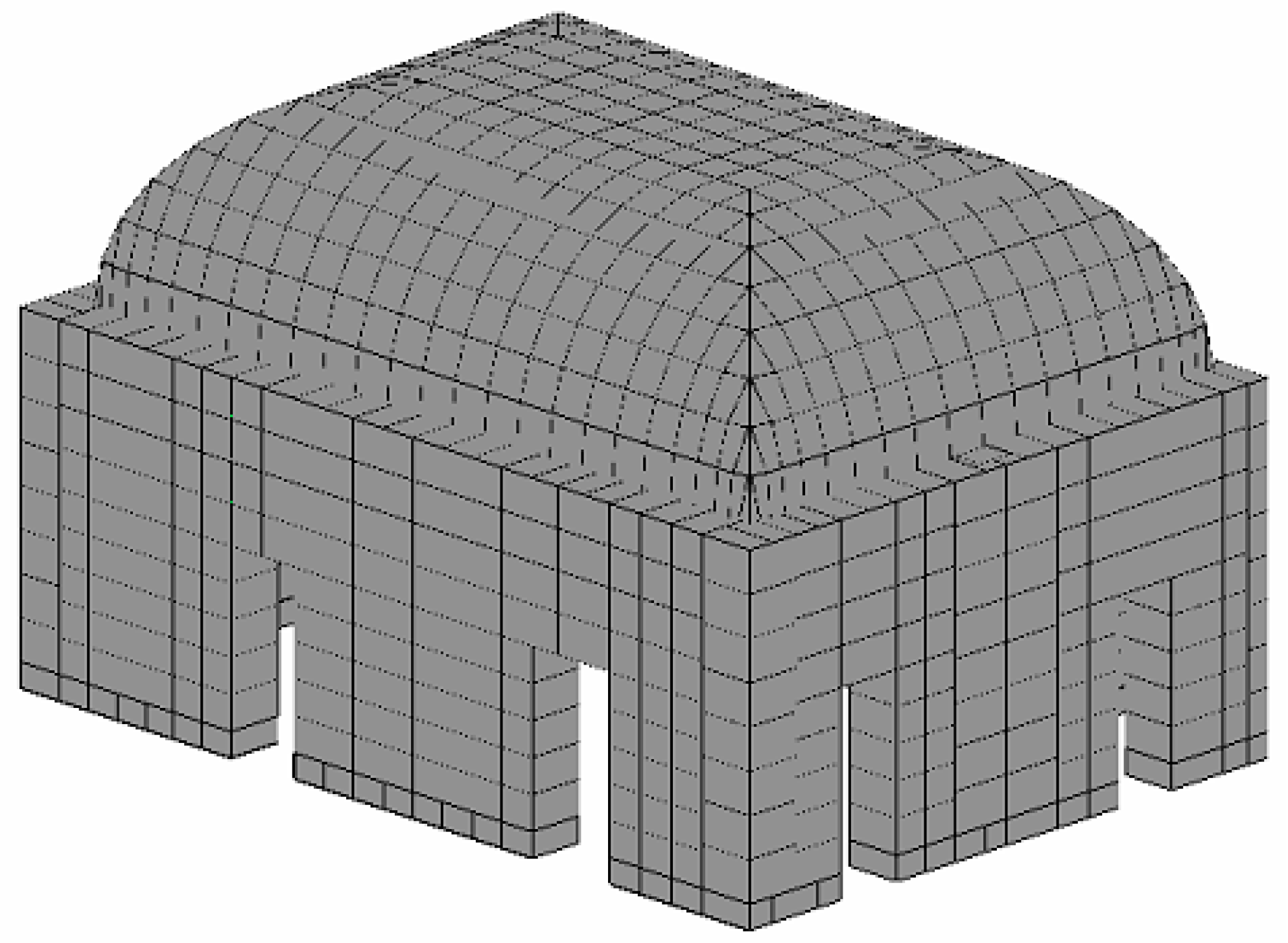
3. The Numerical Modelling Approach
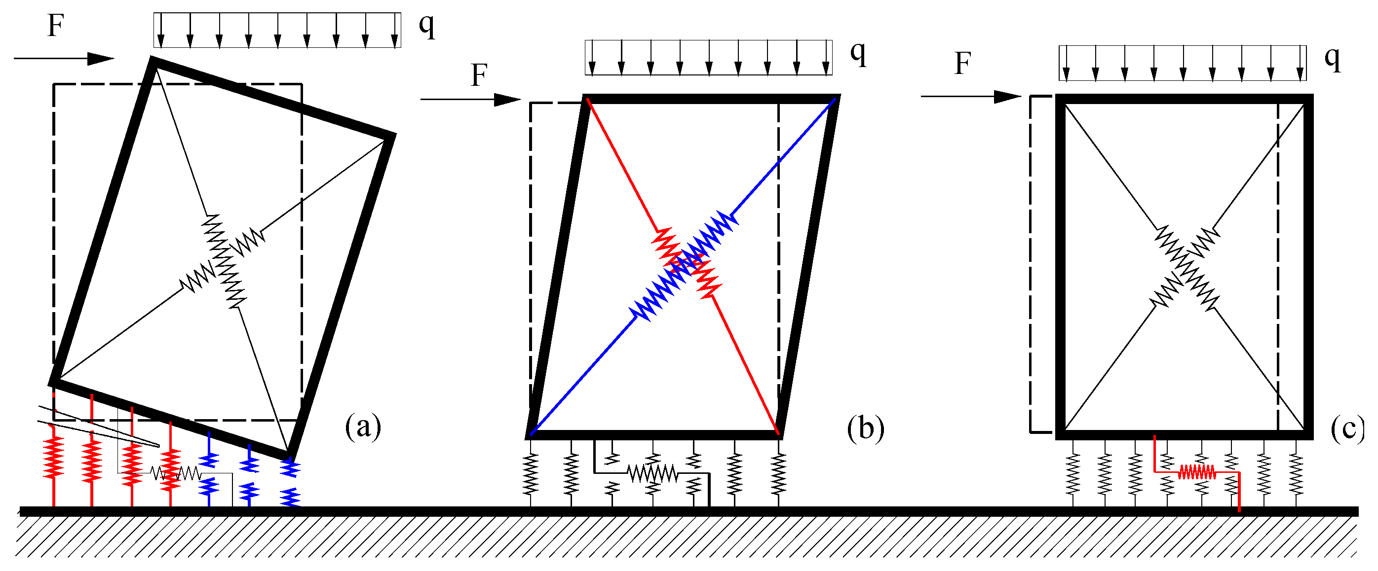
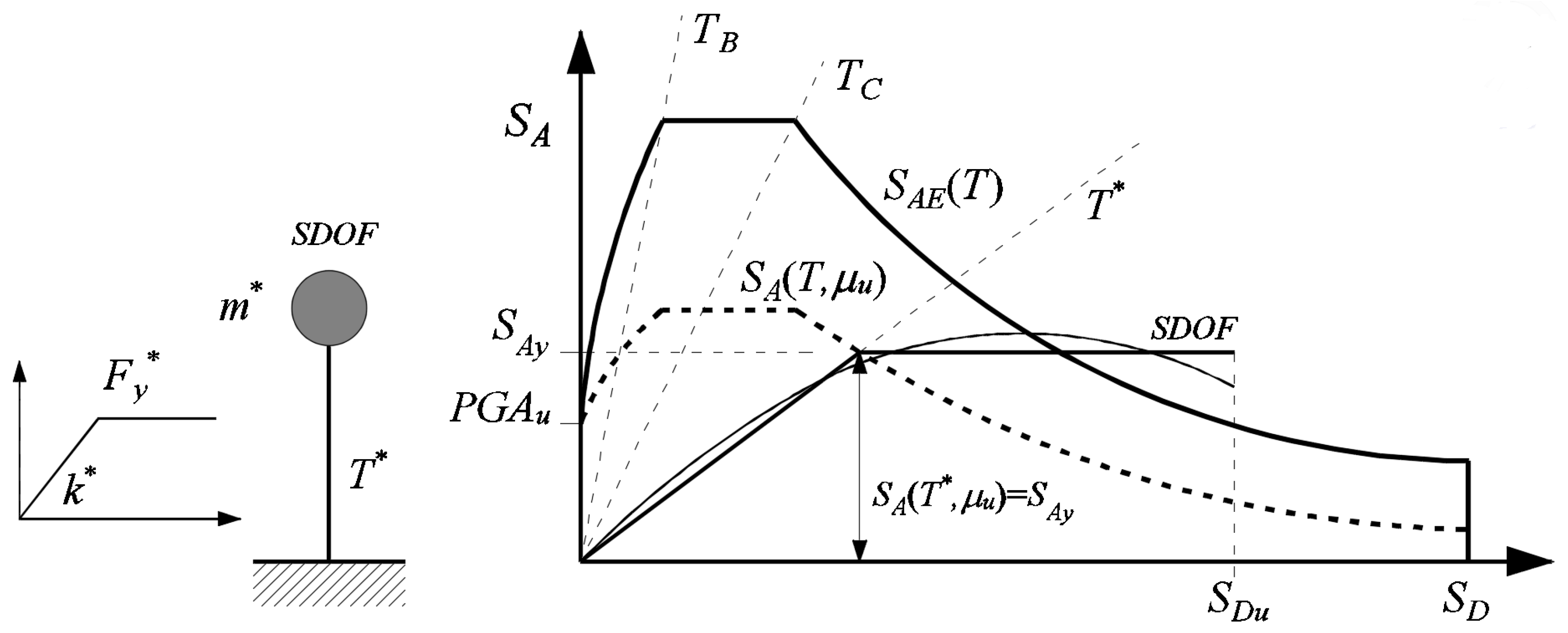
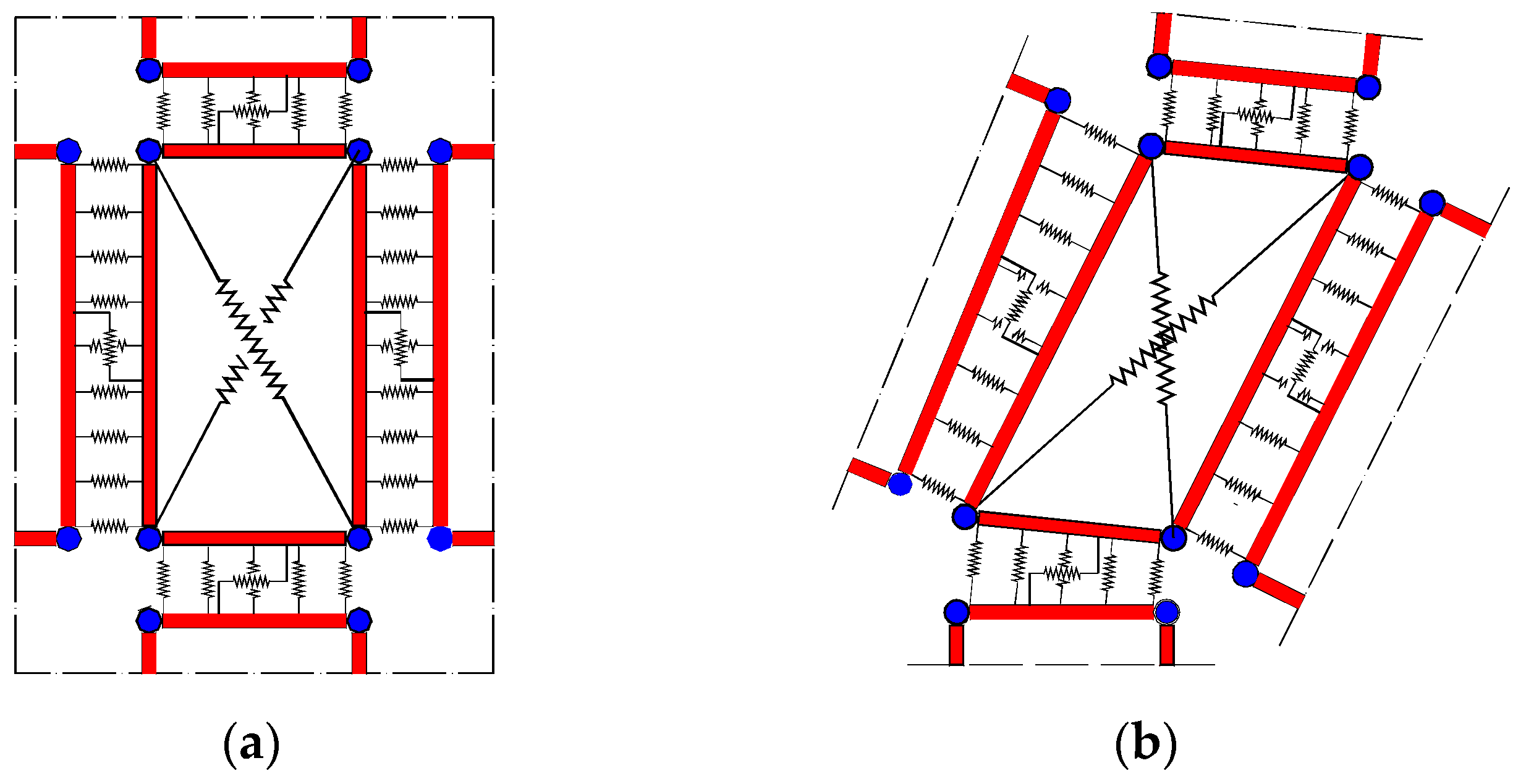
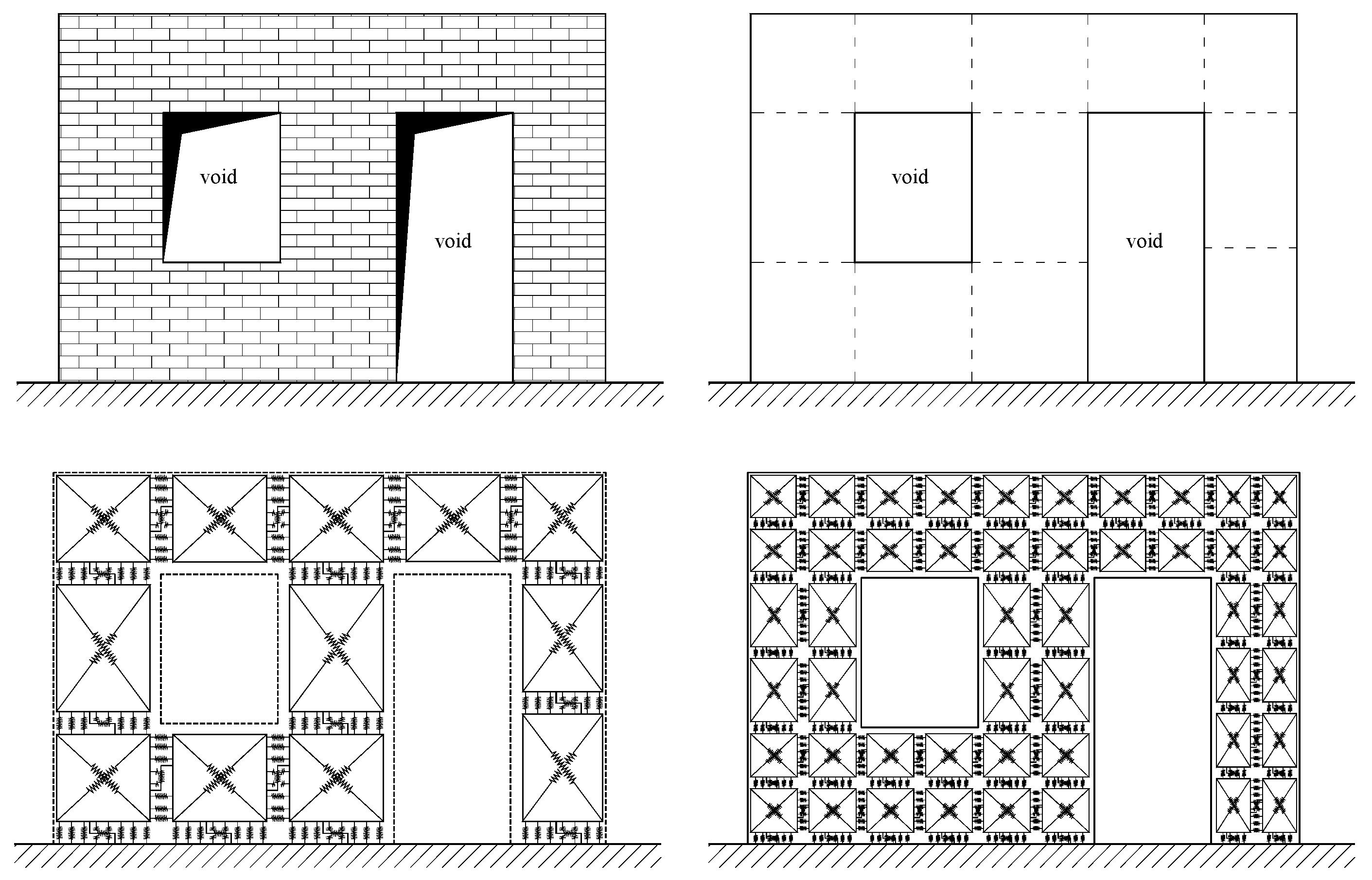
3.1. The In-Plane Macro Model
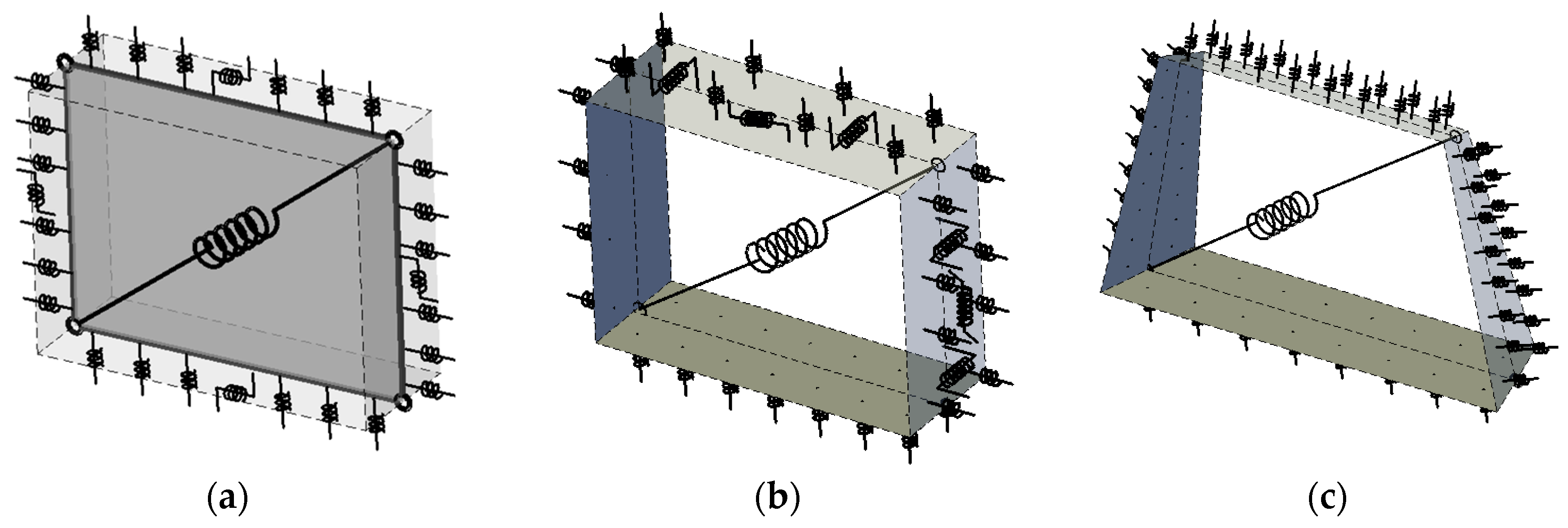
3.2. The Model for Curved Masonry Structures
4. The Numerical Simulations
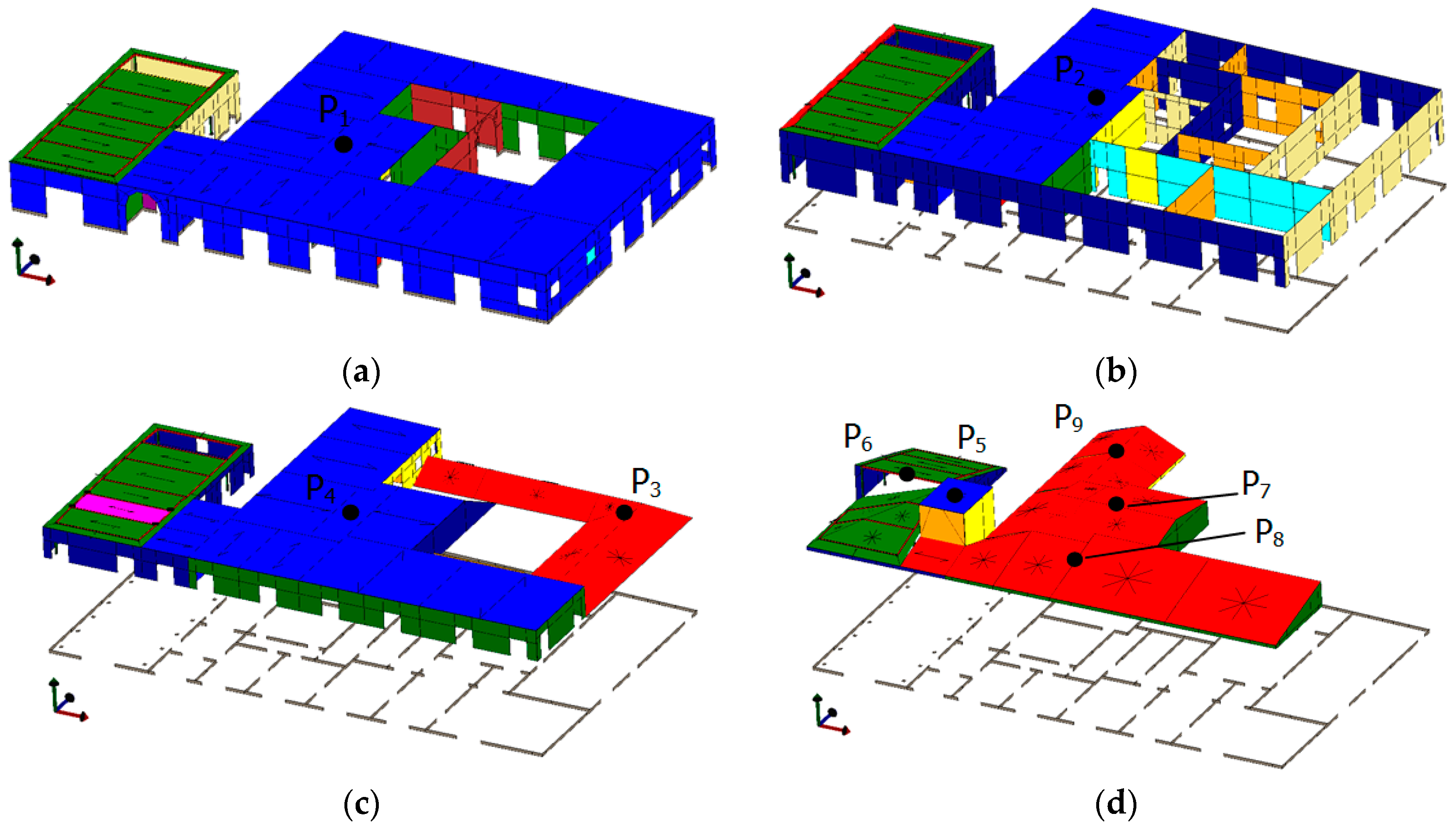
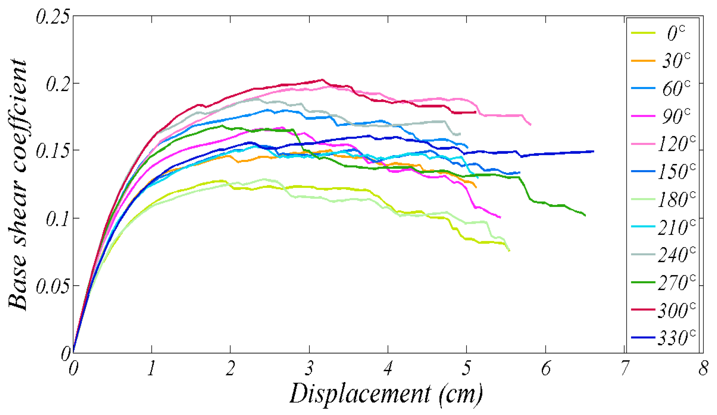
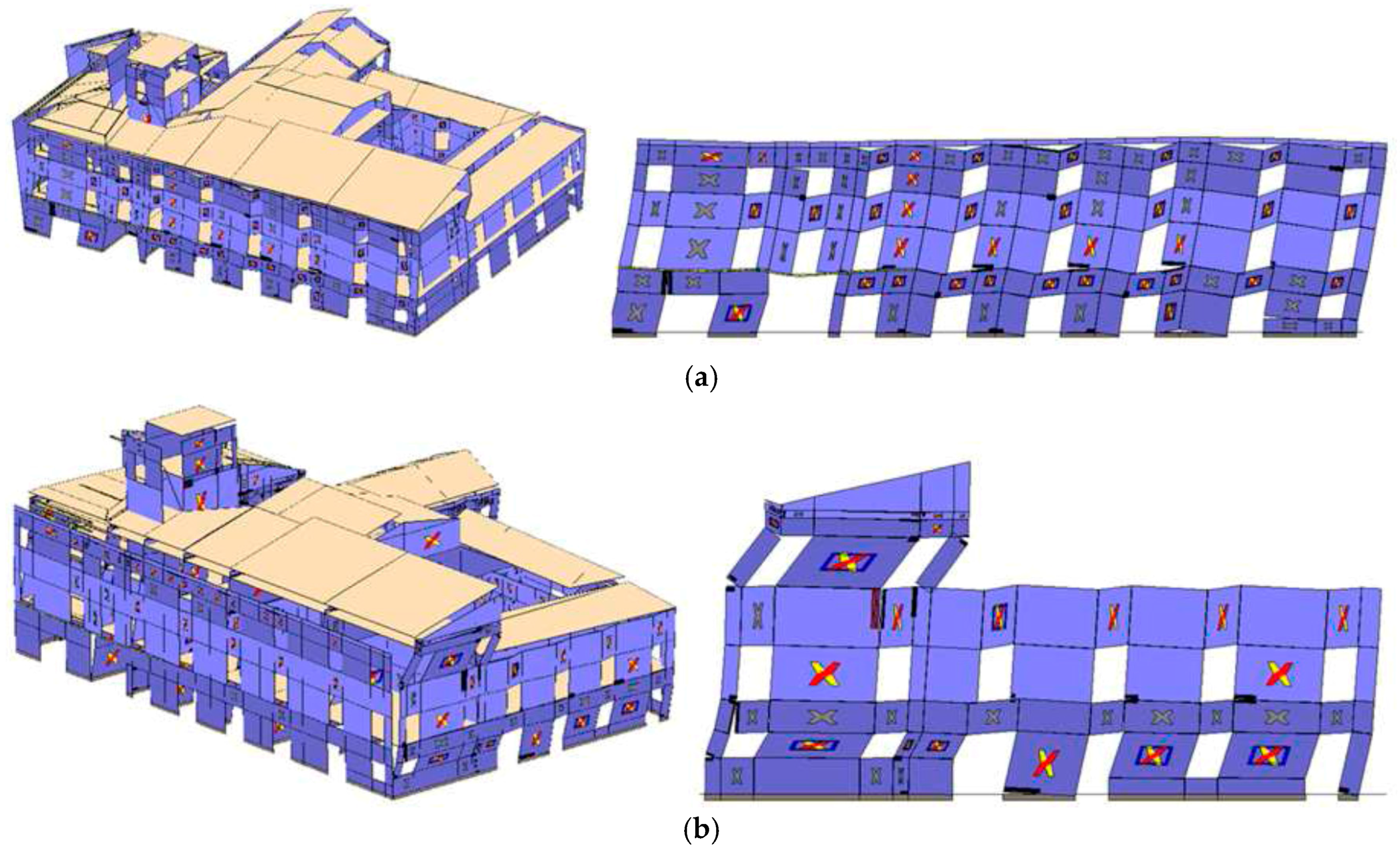
4.1. Global Behaviour of the Building
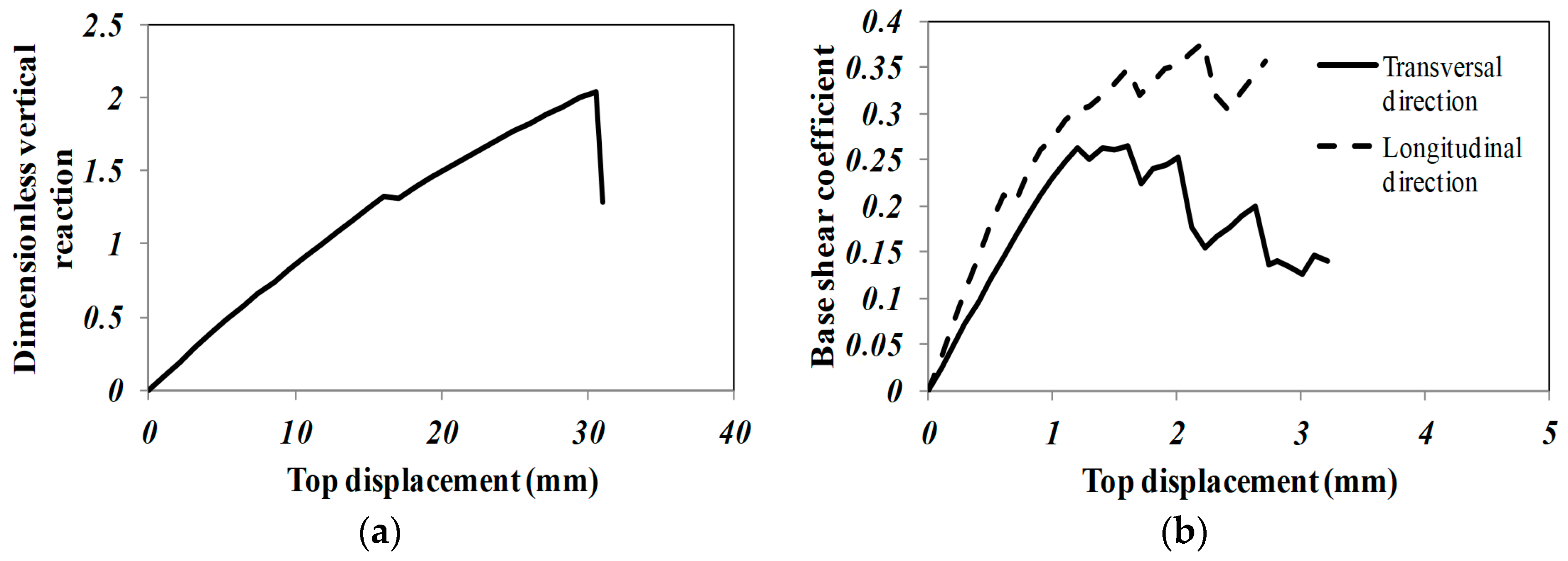
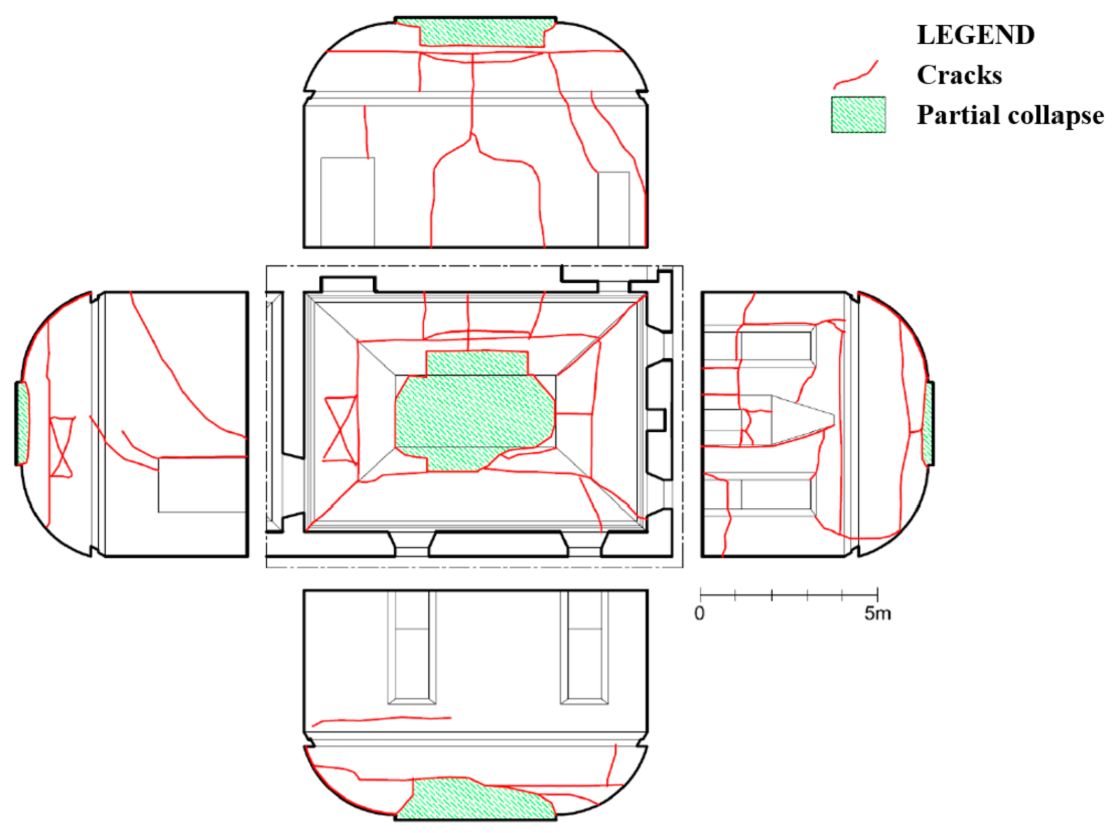
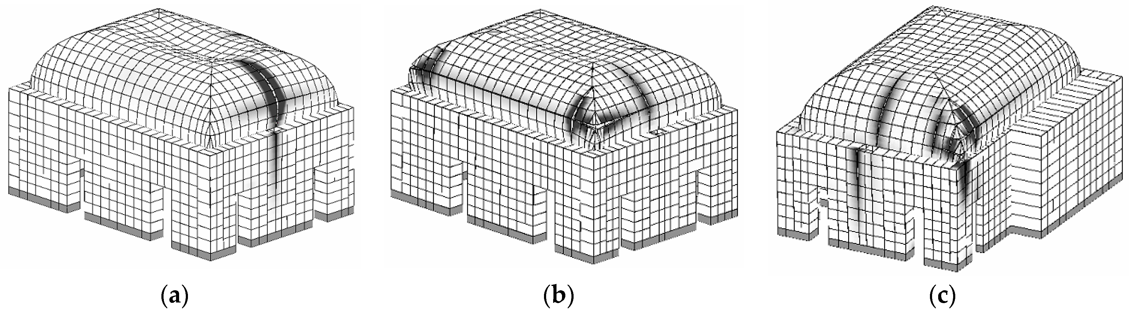
4.2. The Local Response of the Noble Hall
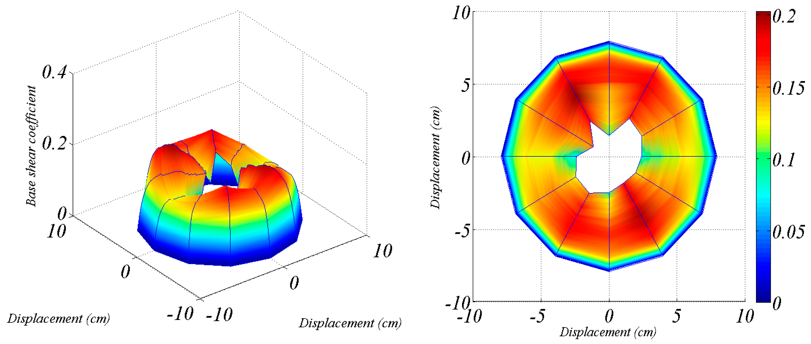
5. Global Seismic Assessment
6. Conclusions
Acknowledgments
Author Contributions
Conflicts of Interest
References
- Chioccarelli, E.; Iervolino, I. Near-source seismic demand and pulse-like records: A discussion for L’Aquila earthquake. Earthq. Eng. Struct. Dyn. 2010, 39, 1039–1062. [Google Scholar] [CrossRef]
- Indirli, M.; Kouris, L.A.S.; Formisano, A.; Borg, R.P.; Mazzolani, F.M. Seismic damage assessment of unreinforced masonry structures after the Abruzzo 2009 earthquake: The case study of the historical centers of L’Aquila and Castelvecchio Subequo. Int. J. Archit. Herit. 2013, 7, 536–578. [Google Scholar] [CrossRef]
- Carocci, C.F. Small centres damaged by 2009 L’Aquila earthquake: On site analyses of historical masonry aggregates. Bull. Earthq. Eng. 2012, 10, 45–71. [Google Scholar] [CrossRef]
- Santucci de Magistris, F.; D’onofrio, A.; Evangelista, L.; Foti, S.; Maraschini, M.; Monaco, P.; Amoroso, S.; Totani, G.; Lanzo, G.; Pagliaroli, A.; et al. Geotechnical characterization of the Aterno Valley for site response analysis. Riv. Ital. Geotec. 2013, 47, 23–43. [Google Scholar]
- Brandonisio, G.; Lucibello, G.; Mele, E.; Luca, A.D. Damage and performance evaluation of masonry churches in the 2009 L’Aquila earthquake. Eng. Fail. Anal. 2013, 34, 693–714. [Google Scholar] [CrossRef]
- Lagomarsino, S. Damage assessment of churches after L’Aquila earthquake (2009). Bull. Earthq. Eng. 2012, 10, 73–92. [Google Scholar] [CrossRef]
- Boscato, G.; Pizzolato, M.; Russo, S.; Tralli, A. Seismic behavior of a complex historical church in L’Aquila. Int. J. Archit. Herit. 2014, 8, 718–757. [Google Scholar] [CrossRef]
- Gattulli, V.; Antonacci, E.; Vestroni, F. Field observations and failure analysis of the Basilica S. Maria di Collemaggio after the 2009 L’Aquila earthquake. Eng. Fail. Anal. 2013, 34, 715–734. [Google Scholar] [CrossRef]
- Pantò, B.; Cannizzaro, F.; Caddemi, S.; Caliò, I. 3D macro-element modelling approach for seismic assessment of historical masonry churches. Adv. Eng. Softw. 2016, 97, 40–59. [Google Scholar] [CrossRef]
- Cimellaro, G.P.; Piantà, S.; De Stefano, A. Output-only modal identification of ancient L’Aquila city hall and civic tower. J. Struct. Eng. 2012, 138, 481–491. [Google Scholar] [CrossRef]
- Ceci, A.M.; Contento, A.; Fanale, L.; Galeota, D.; Gattulli, V.; Lepidi, M.; Potenza, F. Structural performance of the historic and modern buildings of the University of L’Aquila during the seismic events of April 2009. Eng. Struct. 2010, 32, 1899–1924. [Google Scholar] [CrossRef]
- Cardoso, R.; Lopes, M.; Bento, R. Seismic evaluation of old masonry buildings. Part I: Method description and application to a case-study. Eng. Struct. 2005, 27, 2024–2035. [Google Scholar] [CrossRef]
- Mallardo, V.; Malvezzi, R.; Milani, E.; Milani, G. Seismic vulnerability of historical masonry buildings: A case study in Ferrara. Eng. Struct. 2008, 30, 2223–2241. [Google Scholar] [CrossRef]
- Betti, M.; Bartoli, G.; Orlando, M. Evaluation study on structural fault of a Renaissance Italian palace. Eng. Struct. 2010, 32, 1801–1813. [Google Scholar] [CrossRef]
- Castellazzi, G.; D’Altri, A.M.; De Miranda, S.; Ubertini, S. An innovative numerical modeling strategy for the structural analysis of historical monumental buildings. Eng. Struct. 2017, 132, 229–248. [Google Scholar] [CrossRef]
- Castori, G.; Borri, A.; De Maria, A.; Corradi, M.; Sisti, R. Seismic vulnerability assessment of a monumental masonry building. Eng. Struct. 2017, 136, 454–465. [Google Scholar] [CrossRef]
- Andreini, M.; De Falco, A.; Giresini, L.; Sassu, M. Structural analysis and consolidation strategy of the historic Mediceo Aqueduct in Pisa (Italy). Appl. Mech. Mater. 2013, 351–352, 1354–1357. [Google Scholar] [CrossRef]
- Caliò, I.; Cannizzaro, F.; Marletta, M.; Intelisano, M.; Pantò, B.; Caponetto, R.; Margani, G.; Lepidi, M. L’università e la Ricerca per l’Abruzzo: Il Patrimonio Culturale Dopo il Terremoto del 6 Aprile 2009 (In Italian); Milano, L., Morisi, C., Calderini, C., Donatelli, A., Eds.; TEXTUS EDIZIONI: L’Aquila, Italy, 2009. [Google Scholar]
- Caliò, I.; Marletta, M.; Pantò, B. A new discrete element model for the evaluation of the seismic behaviour of unreinforced masonry buildings. Eng. Struct. 2012, 40, 327–338. [Google Scholar] [CrossRef]
- Caliò, I.; Pantò, B. A macro-element modelling approach of Infilled Frame Structures. Comput. Struct. 2014, 143, 91–107. [Google Scholar] [CrossRef]
- Caliò, I.; Cannizzaro, F.; D’Amore, E.; Marletta, M.; Pantò, B. A new discrete-element approach for the assessment of the seismic resistance of composite reinforced concrete-masonry buildings. In Proceedings of the Seismic Engineering International Conference Commemorating the 1908 Messina and Reggio Calabria Earthquake, Reggio Calabria, Italy, 8–11 July 2008; Volume 1020, pp. 832–839. [Google Scholar]
- Caddemi, S.; Caliò, I.; Cannizzaro, F.; Pantò, B. A new computational strategy for the seismic assessment of infilled frame structures. In Proceedings of the 2013 Civil-Comp, Sardinia, Italy, 3–6 September 2013. [Google Scholar]
- Marques, R.; Lourenço, P.B. Possibilities and comparison of structural component models for the seismic assessment of modern unreinforced masonry buildings. Comput. Struct. 2011, 89, 2079–2091. [Google Scholar] [CrossRef] [Green Version]
- Bartoli, G.; Betti, M.; Biagini, P.; Borghini, A. Epistemic Uncertainties in Structural Modeling: A Blind Benchmark for Seismic Assessment of Slender Masonry Towers. J. Perform. Constr. Facil. 2017, 31, 04017067. [Google Scholar] [CrossRef]
- Pantò, B.; Cannizzaro, F.; Caliò, I.; Lourenço, P.B. Numerical and experimental validation of a 3D macro-model for the in-plane and out-of-plane behaviour of unreinforced masonry walls. Int. J. Archit. Herit. 2017, 11, 1–19. [Google Scholar]
- Cannizzaro, F.; Lourenço, P.B. Simulation of Shake Table Tests on Out-of-Plane Masonry Buildings. Part (VI): Discrete Element Approach. Int. J. Archit. Herit. 2017, 11, 125–142. [Google Scholar] [CrossRef]
- Caliò, I.; Cannizzaro, F.; Marletta, M. A discrete element for modeling masonry vaults. Adv. Mater. Res. 2010, 133–134, 447–452. [Google Scholar] [CrossRef]
- Caddemi, S.; Caliò, I.; Cannizzaro, F.; Pantò, B. The Seismic Assessment of Historical Masonry Structures. In Proceedings of the 12th International Conference on Computational Structures Technology, Naples, Italy, 2–5 September 2014. [Google Scholar]
- European Committee for Standardization. EN 1998-3: 2005 Part 3 of the Eurocode 8—Design of Structures for Earthquake Resistance. Section 2: Performance Requirements and Compliance Criteria. Sub-Section 2.2: Compliance Criteria; European Committee for Standardization: Brussels, Belgium, 2005. [Google Scholar]
- European Committee for Standardization. EN 1998-3: 2005 Eurocode 8: Design of Structures for Earthquake Resistance, Part 3: Assessment and Retrofitting of Buildings; European Committee for Standardization: Brussels, Belgium, 2005. [Google Scholar]
- Pantò, B.; Caliò, I.; Lourenço, P.B. Seismic safety evaluation of reinforced concrete masonry infilled frames using macro modelling approach. Bull. Earthq. Eng. 2017, 15, 3871–3895. [Google Scholar] [CrossRef]
- Dander, M.; Moretti, M. Architettura Civile Aquilana—Dal XIV al XIX Secolo; L.U. Japadre 735 Editore: L’Aquila, Italy, 1974. (In Italian) [Google Scholar]
- Decreto Ministeriale 20/11/1987: Norme tecniche per la progettazione, esecuzione e collaudo degli edifici in muratura e per il loro consolidamento. Available online: http://www.dist.unina.it/doc/norme/04/04%2020-11-87.pdf (accessed on 1 September 2017). (In Italian).
- Casapulla, C.; Portioli, F. Experimental tests on the limit states of dry-jointed tuff blocks. Mater. Struct. 2016, 49, 751–767. [Google Scholar] [CrossRef]
- Casapulla, C.; Maione, A. Formulating the Torsion Strength of Dry-Stacked Stone Blocks by Comparing Convex and Concave Contact Formulations and Experimental Results. Indian J. Sci. Technol. 2016, 9, 1–7. [Google Scholar] [CrossRef]
- Casapulla, C.; Argiento, L.U. The comparative role of friction in local out-of-plane mechanisms of masonry buildings. Pushover analysis and experimental investigation. Eng. Struct. 2016, 126, 158–173. [Google Scholar] [CrossRef]
- Caddemi, S.; Caliò, I.; Cannizzaro, F.; Occhipinti, G.; Pantò, B. A parsimonious discrete model for the seismic assessment of monumental structures. In Proceedings of the 2015 Fifteenth International Conference on Civil, Structural and Environmental Engineering Computing, Prague, Czech, 1–4 September 2015. [Google Scholar]
- NTC (2008): Approvazione delle nuove norme tecniche per le costruzioni, Gazzetta Ufficiale della Repubblica Italiana, n. 29 del 4 febbraio 2008—Suppl. Ordinario n. 30. Available online: http://www.cslp.it/cslp/index.php?option=com_docman&task=doc_download&gid=3269&Itemid=10 (accessed on 1 September 2017). (In Italian).
- Fajfar, P.; Gašperšič, P. The N2 method for the seismic damage analysis of RC buildings. Earthq. Eng. Struct. Dyn. 1996, 25, 31–46. [Google Scholar] [CrossRef]


| Masonry Typology | E (MPa) | G (MPa) | τ0 (MPa) | σc (MPa) | Gc (N/mm) | σt (MPa) | Gt (N/mm) | w (kN/m3) |
|---|---|---|---|---|---|---|---|---|
| Masonry walls | 690 | 230 | 0.02 | 1.0 | 0.1 | 0.05 | 0.02 | 19 |
| Vault | 1200 | 480 | 0.04 | 3.0 | 0.3 | 0.1 | 0.05 | 19 |
| Id | Level (m) | Description | Mass (t) |
|---|---|---|---|
| P1 | 3.50 | First Level | 2541.9 |
| P2 | 7.50 | Second Level | 1410.5 |
| P3 | 10.20 | Pitched roof | 1070.9 |
| P4 | Plan floor | ||
| P5 | 14.45 | Tower | 689.4 |
| P6 | Reinforced concrete part | ||
| P7 | Central pitched roof | ||
| P8 | Frontal pitched roof | ||
| P9 | Rearward pitched roof | ||
| P10 | 17.75 | Tower | 31.7 |
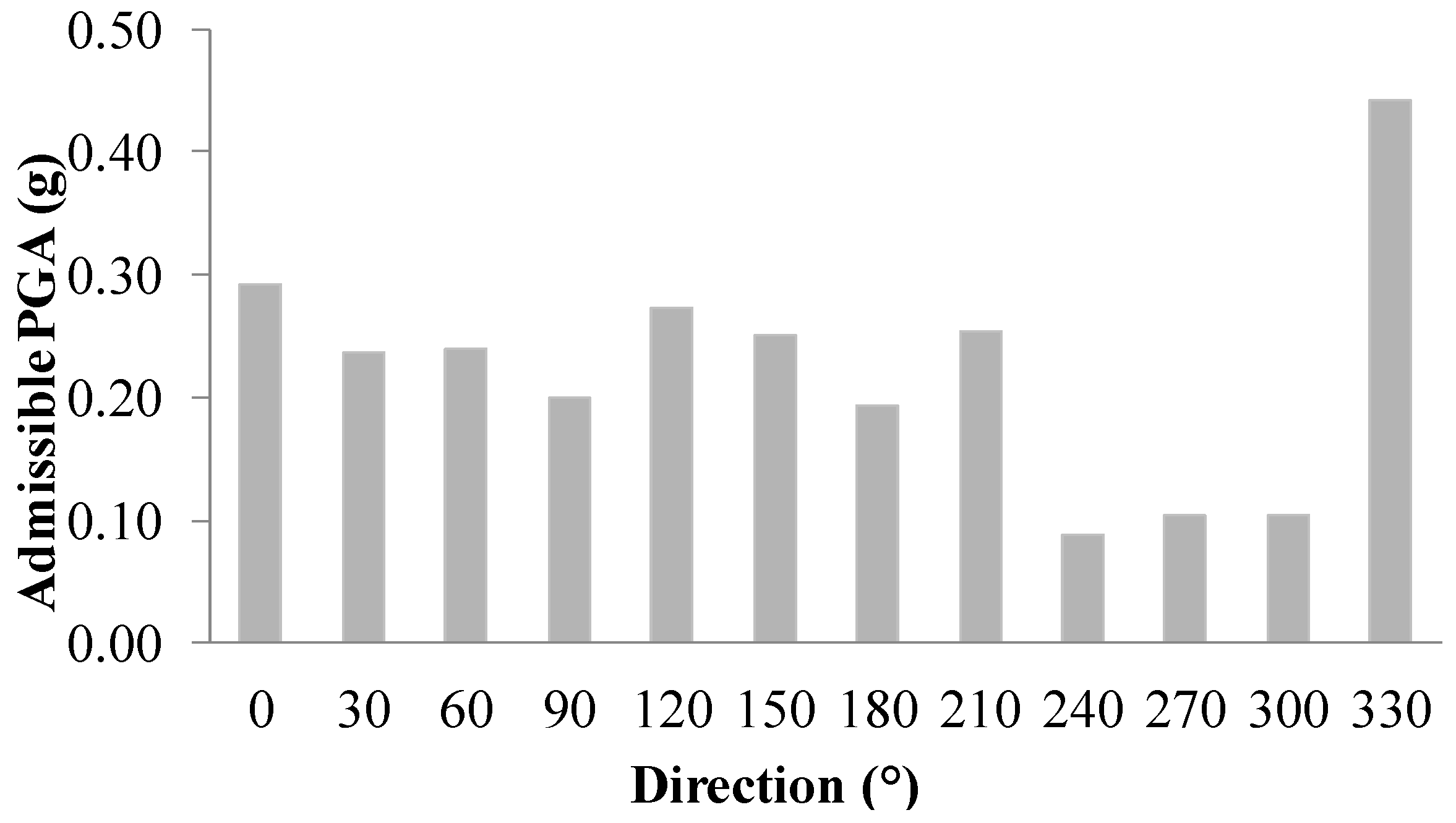
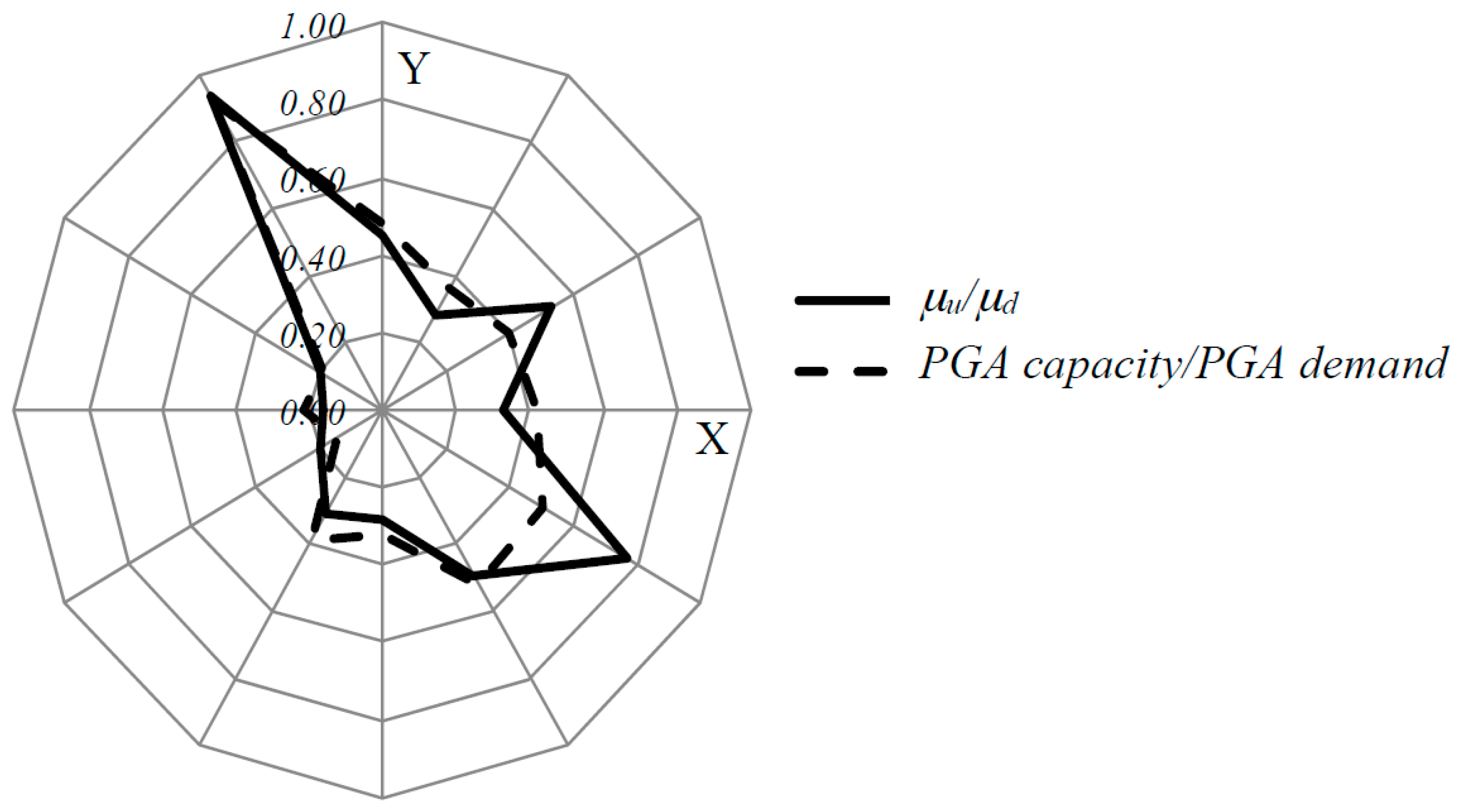
| Direction (°) | Azimuth (°) | F*y (kN) | k* (kN/cm) | T* (s) | SAy (g) | SDy (cm) | μu (-) | PGA Capacity (g) | PGA Demand (g) |
|---|---|---|---|---|---|---|---|---|---|
| 0 | 300 | 4559 | 10044 | 0.33 | 0.16 | 0.45 | 6.29 | 0.29 | 0.60 |
| 30 | 270 | 5370 | 12517 | 0.30 | 0.19 | 0.43 | 4.82 | 0.24 | 0.66 |
| 60 | 240 | 6451 | 13360 | 0.29 | 0.23 | 0.48 | 4.20 | 0.24 | 0.60 |
| 90 | 210 | 5975 | 12311 | 0.30 | 0.22 | 0.49 | 3.64 | 0.20 | 0.48 |
| 120 | 180 | 7066 | 12878 | 0.29 | 0.25 | 0.55 | 4.28 | 0.27 | 0.55 |
| 150 | 150 | 5496 | 11449 | 0.31 | 0.20 | 0.48 | 4.78 | 0.25 | 0.48 |
| 180 | 120 | 4599 | 10543 | 0.33 | 0.17 | 0.44 | 4.21 | 0.19 | 0.60 |
| 210 | 90 | 5471 | 14312 | 0.28 | 0.20 | 0.38 | 5.43 | 0.25 | 0.66 |
| 240 | 60 | 6407 | 13364 | 0.29 | 0.23 | 0.48 | 1.54 | 0.09 | 0.60 |
| 270 | 30 | 6041 | 17596 | 0.25 | 0.18 | 0.34 | 2.24 | 0.10 | 0.48 |
| 300 | 0 | 6591 | 19184 | 0.24 | 0.24 | 0.34 | 2.14 | 0.10 | 0.55 |
| 330 | 330 | 5751 | 10567 | 0.33 | 0.21 | 0.54 | 7.72 | 0.44 | 0.48 |
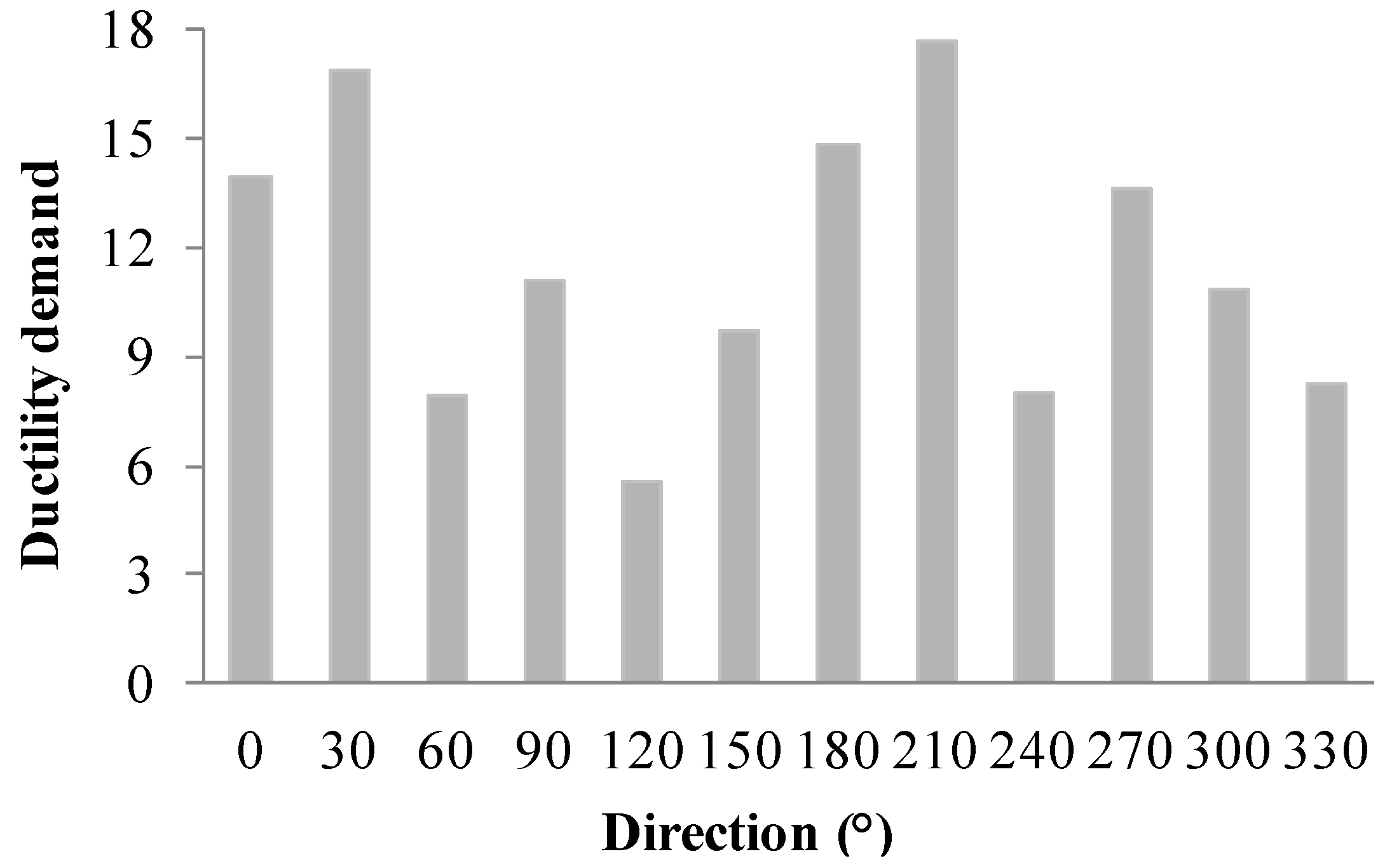
| Direction (°) | Azimuth (°) | μd (-) |
|---|---|---|
| 0 | 300 | 13.97 |
| 30 | 270 | 16.83 |
| 60 | 240 | 7.89 |
| 90 | 210 | 11.06 |
| 120 | 180 | 5.60 |
| 150 | 150 | 9.69 |
| 180 | 120 | 14.86 |
| 210 | 90 | 17.63 |
| 240 | 60 | 7.97 |
| 270 | 30 | 13.57 |
| 300 | 0 | 10.86 |
| 330 | 330 | 8.23 |
© 2017 by the authors. Licensee MDPI, Basel, Switzerland. This article is an open access article distributed under the terms and conditions of the Creative Commons Attribution (CC BY) license (http://creativecommons.org/licenses/by/4.0/).
Share and Cite
Cannizzaro, F.; Pantò, B.; Lepidi, M.; Caddemi, S.; Caliò, I. Multi-Directional Seismic Assessment of Historical Masonry Buildings by Means of Macro-Element Modelling: Application to a Building Damaged during the L’Aquila Earthquake (Italy). Buildings 2017, 7, 106. https://doi.org/10.3390/buildings7040106
Cannizzaro F, Pantò B, Lepidi M, Caddemi S, Caliò I. Multi-Directional Seismic Assessment of Historical Masonry Buildings by Means of Macro-Element Modelling: Application to a Building Damaged during the L’Aquila Earthquake (Italy). Buildings. 2017; 7(4):106. https://doi.org/10.3390/buildings7040106
Chicago/Turabian StyleCannizzaro, Francesco, Bartolomeo Pantò, Marco Lepidi, Salvatore Caddemi, and Ivo Caliò. 2017. "Multi-Directional Seismic Assessment of Historical Masonry Buildings by Means of Macro-Element Modelling: Application to a Building Damaged during the L’Aquila Earthquake (Italy)" Buildings 7, no. 4: 106. https://doi.org/10.3390/buildings7040106