Article

Mechanical Properties of Innovative, Multi-Layer Composite Laminated Panels

1
Department of Civil and Environmental Engineering, University of Alberta, Edmonton, AB T6G 1H9, Canada
2
Integrated Wood Engineering, University of Northern British Columbia, Prince George, BC V2N 4Z9, Canada
*
Author to whom correspondence should be addressed.
Buildings 2018, 8(10), 142; https://doi.org/10.3390/buildings8100142
Submission received: 4 September 2018 / Revised: 1 October 2018 / Accepted: 10 October 2018 / Published: 12 October 2018

Abstract

:
Cross-laminated timber (CLT) possesses both good shape stability and possible two-way force transfer ability due to its crosswise lamination. However, the transverse layers in CLT are prone to rolling shear failure under an out-of-plane load. An innovative multi-layer composite laminated panel (CLP) was developed by combining structural composite lumber (SCL) and dimension lumber to overcome the rolling shear failure while maintaining the high mechanical performance and aesthetic appearance of natural wood. The mechanical properties of 5-layer CLP that consisted of laminated strand lumber (LSL) and dimension lumber with different layups were evaluated by both static and modal tests. The results showed that the shear resistance, bending stiffness, and moment resistance of CLP were up to 143%, 43%, and 87% higher than their counterparts of regular CLT, respectively. The failure modes observed in both shear and bending tests indicated that the use of LSL in transverse layers could eliminate the potential rolling shear failure in CLT. With the lamination properties from components tests as inputs, the validity of shear analogy method was assessed by test results. The mechanical properties can be well predicted by shear analogy method except for the bending moment resistance of CLP and CLT with either rolling failure in the cross layer or tension failure in the bottom layer.

1. Introduction

Mass timber is an emerging building material that has gained popularity worldwide with the development of mass timber construction in recent years. Mass timber panels (MTPs) are often referred to as panelized engineered wood products of a large dimension and cross section. MTPs cover a broad range of wood products from the well-known traditional, parallel-laminated elements including glued-laminated timber (GLT), nail-laminated timber (NLT), and dowel-laminated timber (DLT) to the popular cross-laminated timber (CLT) and structural composite lumber (SCL). GLT, NLT, and DLT are manufactured by edge-gluing, nail-jointing, and dowel-jointing lumber planks with the wood grain of all planks aligned in the same direction, respectively. They are often used as one-way floor slabs in mass timber construction. CLT is made from graded sawn lumber planks that are orthogonally glued together with a structural adhesive. Due to the orthogonal layer arrangement, CLT has the benefit of resisting out-of-plane loading through the two-way action of the panel plane. However, since the cross-layers with a radial-tangential cross section have a relatively low shear strength and modulus, CLT panels are prone to rolling shear failures when exposed to shear stress perpendicular to the grain, as well as excessive deflection under out-of-plane load. In addition, edge-gluing is not mandatory in CLT production [1]. The gaps in the non-edge-glued CLT panels not only can reduce the mechanical properties such as in-plane shear strength and modulus [2,3] but also are unfavorable to fire and building physics considerations. SCL is an important category of engineered wood product in North America, which includes laminated veneer lumber (LVL), laminated strand lumber (LSL), oriented strand lumber (OSL), and parallel strand lumber (PSL). These products have been already marketed in structural lumber dimensions in North America for a long time before the advent of mass timber panel construction. In fact, SCL is often produced in massive panel size known as billets before being machined into primarily beam-like members. Generally, SCL has great potential due to its two-dimensional load-transfer ability and superior mechanical properties. The North American standard for performance-rated CLT [4] allows for the use of SCL in producing CLT. Therefore, attempts were made to modify generic CLT with SCL to overcome the drawbacks of CLT such as the rolling shear issues and gaps of non-edge glued layers. Three-layer hybrid CLT (HCLT) made from spruce-pine-fir (SPF) and LSL were reported in [5,6]. The bending modulus and strength of HCLT with LSL as outer layers were 19% and 36% higher than those of CLT, respectively [5]. In [6], the HCLT with LSL as core layer showed a 23% higher mean bending stress at failure and a 46% higher mean shear strength than the corresponding values of CLT, respectively. Both studies indicated that the rolling shear failure was mitigated by using LSL as the core layer. It should be noted that the LSL used in [6] was of the same size as regular dimension lumber, which did not utilize the advantage of LSL as a panel product.
Recently, comprehensive research has been conducted to develop an innovative multi-layer composite laminated panel (CLP) using graded sawn lumber and SCL at the University of New Brunswick [7] and the University of Alberta [8]. Both 3-layer [7] and 5-layer [8] CLP with different layups were produced with different combinations of lumber planks, LSL and OSL panels. This paper presents the mechanical properties of 5-layer CLPs including apparent and effective bending stiffness, moment resistance, shear resistance, and stiffness, together with the failure modes. The validation of the shear analogy method in predicting the bending performance of CLPs was also examined with the lamination properties from component tests.

2. Materials and Methods

2.1. Materials

The materials used for fabricating the 5-layer CLPs were dimension lumber planks and full-size LSL panels. The lumber material was #2 or better grade 2” by 4” SPF with cross-sectional dimensions of 38 mm × 89 mm and lengths ranging from 2438 mm to 3048 mm. The dimensions of the LSL panels were 2744 mm (length) × 1220 mm (width) × 38 mm (thickness). The mean moisture content (MC) and density of the lumber and LSL were around 7.4% and 470 kg/m3, and 3.4% and 644 kg/m3, respectively.

2.2. Component Tests

In order to predict and compare the mechanical properties of CLPs with different layups based on their layer properties, test specimens were cut from the raw materials to evaluate the components’ mechanical properties. The bending properties and the tensile strength (UTS) were evaluated in accordance with reference [9]. The modulus of elasticity (MOE) and the modulus of rupture (MOR) of all the materials were measured by third-point bending tests with a span-to-depth ratio of 20. The load and displacement were recorded for the calculation of MOE and MOR. The UTS was measured using a Metriguard tension tester with a specimen gauge length of 1.6 m. Moreover, the planar shear modulus and strength in both strength directions of LSL were evaluated according to [10]. The block shear specimens were prepared and tested using a setup consisting of two aluminum plates with steel knife edges. A load was applied to the knife edges that introduced a shear force onto the specimen that was glued between the two aluminum plates. The load and the displacement between the aluminum plates were recorded for the calculation of shear modulus and strength. The material properties measured in this study together with some reference values are summarized in Table 1.

2.3. Panel Manufacturing

Before the fabrication of CLPs, the manufacturing parameters were developed based on the bond performance study with different surface treatments of SCL [7,8]. It was found to be sufficient for fabricating CLPs using one-component polyurethane (PU) adhesive with a spread rate of 32 g/m2 under cold press with a pressure of 1.38 N/mm2 for 2 h. The lumber planks were planed to provide a clean and smooth glue surface as required in the North American standard for performance rated CLT [4]. Seven symmetrical layups of lumber-LSL and all lumber combinations were produced as illustrated in Figure 1. Butt joints were introduced in the middle of the panel in the second and fourth LSL layers for group 5-A1a and the third layer for group 5-A1b. It was intended to evaluate the effect of butt joints on the mechanical properties of CLP, since edge gluing is not appropriate to SCL panels in the manufacture practice. A butt joint can be seen in Figure 2. After pressing and trimming, the final dimensions of the 5-layer panels were about 2743 mm in length, 1219 mm in width, and 184 mm in thickness.
Table 2 provides the information on the panel layup, the layer orientation, and the number of replicates for bending and shear tests. Within the layup column, “T” stands for timber and “L” stands for LSL. In the layer orientation column, “//” indicates that the major strength direction of the layer was orientated parallel to the long side of the panel, while “⊥” indicates that the minor strength direction of the layer was orientated parallel to the long side of the panel. A total of 17 lumber-LSL CLPs and two generic CLT panels as references were produced. The CLT panels produced in this study can be assigned as V2 grade CLT in [4] according to the lumber species and stress grade. Beam elements were cut from the CLP and CLT panels.

2.4. Modal Tests

Modal test of each bending specimen was conducted under a free-free boundary condition by suspending the beam with two elastic ropes attached to a rigid frame shown in Figure 3. The first and second natural frequencies of each beam specimen were measured by an impact vibration system consisting of an accelerometer, an instrumented impact hammer, a data acquisition device, and experimental modal analysis software. The natural frequencies were used to calculate its dynamic apparent bending stiffness ( E I a p p , d ) based on Euler beam theory [13], as well as its dynamic effective bending stiffness ( E I e f f , d ) and shear stiffness ( G A e f f , d ) based on Timoshenko beam theory [14]. The dynamic apparent bending stiffness can be calculated by
E I a p p , d = 4 π 2 f 1 2 ρ A l 4 / ( β 1 l ) 4
in which f 1 is the fundamental natural frequency, ρ is the density, A is the cross-sectional area, l is the length of the beam, and β 1 l equals 4.73 according to [13].
The dynamic effective bending stiffness and shear stiffness can be determined with the first and second natural frequencies using the method presented in [14]. These two terms are defined as
E I e f f , d = E I g r o s s
G A e f f , d = k G A g r o s s
in which I g r o s s and A g r o s s are the gross moment of inertia and cross-sectional area of the beam and k is the shear correction factor.
Since the shear correction factor of a laminated composite such as CLT and CLP is dependent on its layup and the properties of laminates [15], the effective shear stiffness is defined as k G A g r o s s to avoid ambiguity.

2.5. Static Tests

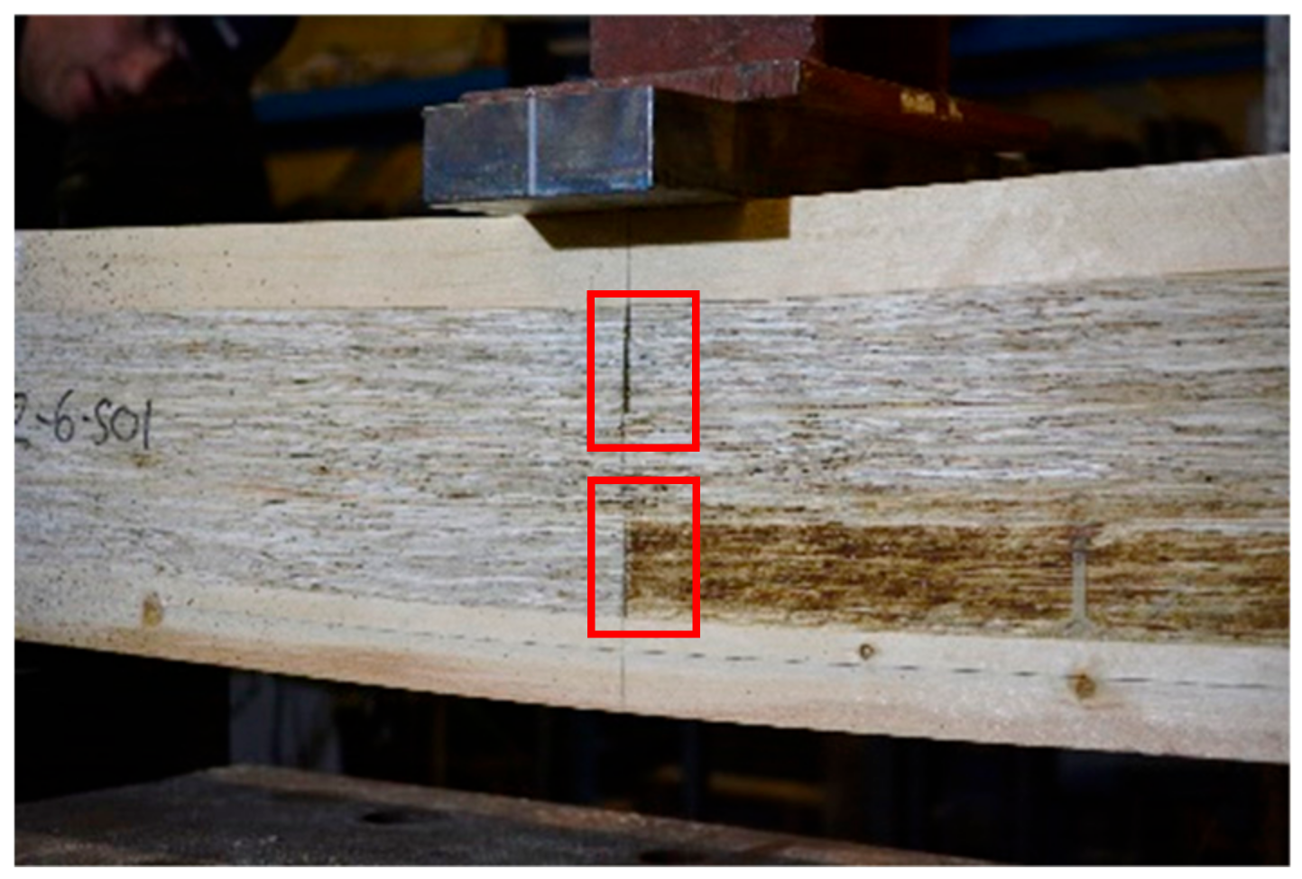
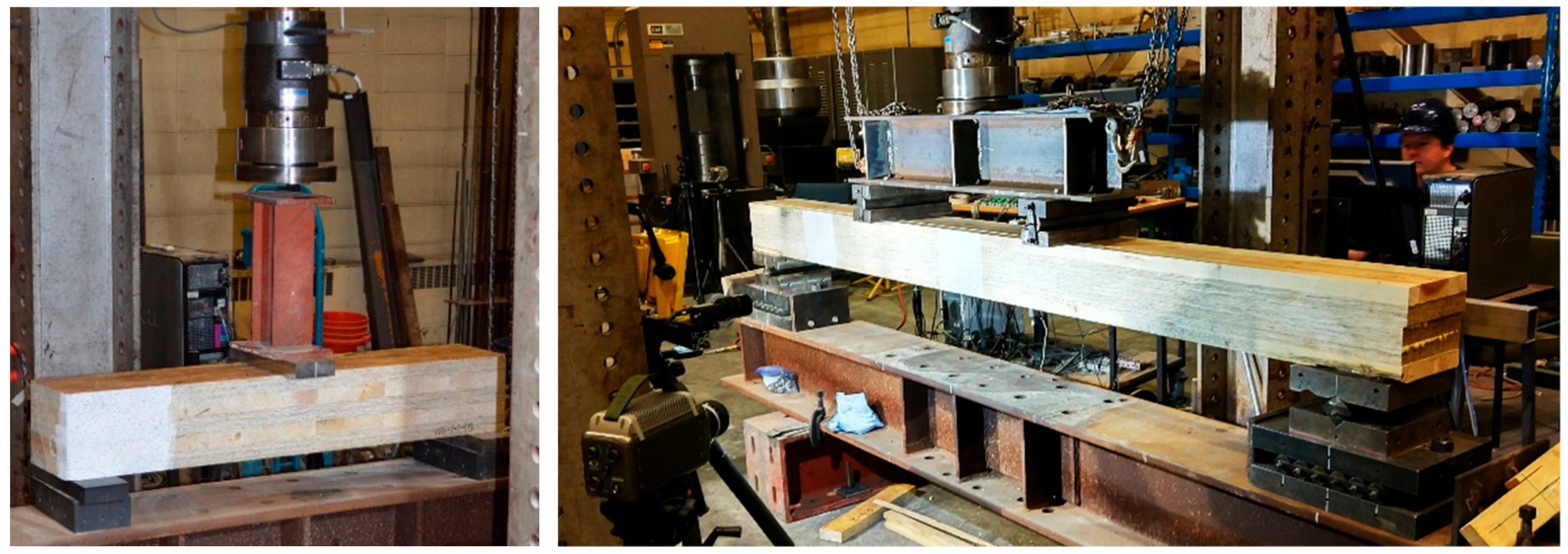
2.5.1. Short-Span Shear Tests

The specimens were tested in short-span shear tests as recommended in [4]. The standard for performance rated CLT recommends an on-centre span equal to 5 to 6 times the specimen depth. The failure load and failure modes were recorded. The test span was at 1000 mm (span-to-depth ratio = 5.5). The tests were undertaken at a displacement rate of 2 mm/min. The shear resistance from static tests, V r , s , can be calculated by
V r , s = F max / 2
in which F max is the maximum load at shear failure.

2.5.2. Third-Point Bending Tests

Then, third-point bending tests were performed according to [7], as shown in Figure 4. The test span and displacement rate were 2500 mm (span-to-depth ratio = 13.6) and 4 mm/min, respectively. The failure load, failure mode, and the deflection at mid-span were recorded during the test. The apparent bending stiffness ( E I a p p , s ) and moment resistance ( M r , s ) can be calculated by
E I a p p , s = 23 1296 × ( P Δ ) × L 2
M r , s = F max 2 × L 3
in which P Δ is the slope of the load-displacement response in the linear range from 10–40% of F max , F max is the maximum load at failure, and L is the test span.

2.6. Shear Analogy Method

Since the shear analogy method has been adopted in the North American CLT product standard ANSI/APA PRG 320 [4] and in the Canadian timber design code CSA O86 [16] for predicting bending stiffness and shear stiffness of CLT based on mechanical properties of laminations, it is necessary to verify its applicability to the CLP products developed in this study. The effective bending stiffness E I e f f , S A , shear stiffness G A e f f , S A , moment resistance M r . S A , and shear resistance V r . S A can be calculated using the following equations:
E I e f f , S A = i n E i b i h i 3 12 + i n E i A i z i 2
G A e f f , S A = a 2 [ h 1 2 G 1 b 1 + i = 2 n 1 h i G i b i + h n 2 G n b n ]  
M r . S A = f b S e f f
V r . S A = min { f v i E I e f f , S A b i ( E S ) z }
in which E i is modulus of elasticity of the ith layer; b i is the width of the ith layer; h i is the thickness of the ith layer; A i is the area of cross-section of the ith layer; z i is the distance from the centroid of the ith layer to the neutral axis of the cross-section; G i and f v i are shear modulus and strength of the ith layer, respectively; a is the centroidal distance between top and bottom layers; S e f f is the effective section modulus, S e f f = 2 E I e f f , s a / ( E 1 h ) ; h is the total thickness; f b is the bending strength of the outer layer; and ( E S ) z is the static moment at location of z, which is the product of the first moment of area and modulus.
For a CLP or CLT beam under short-span bending, the shear stress at failure can be calculated by
τ = V r . s ( E S ) ( z ) E I e f f , S A b
For a CLP or CLT beam under third-point bending test, the apparent bending stiffness based on the shear analogy method, E I a p p , S A , can be calculated by
E I a p p , S A = E I e f f , S A 1 + 9.4 E I e f f , S A G A e f f , S A L 2
in which L is the test span of the beam specimen.

3. Results and Discussion

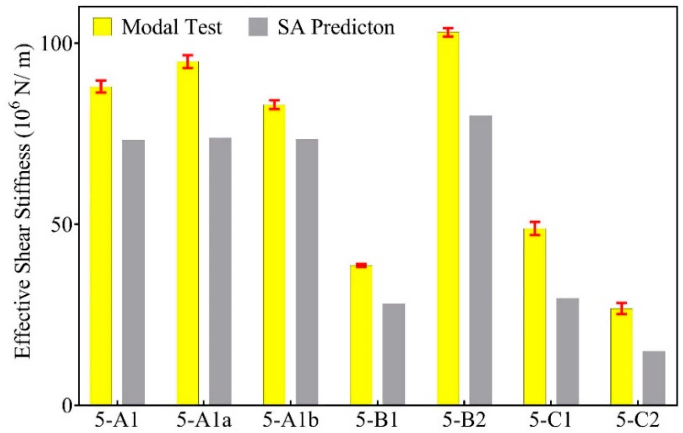
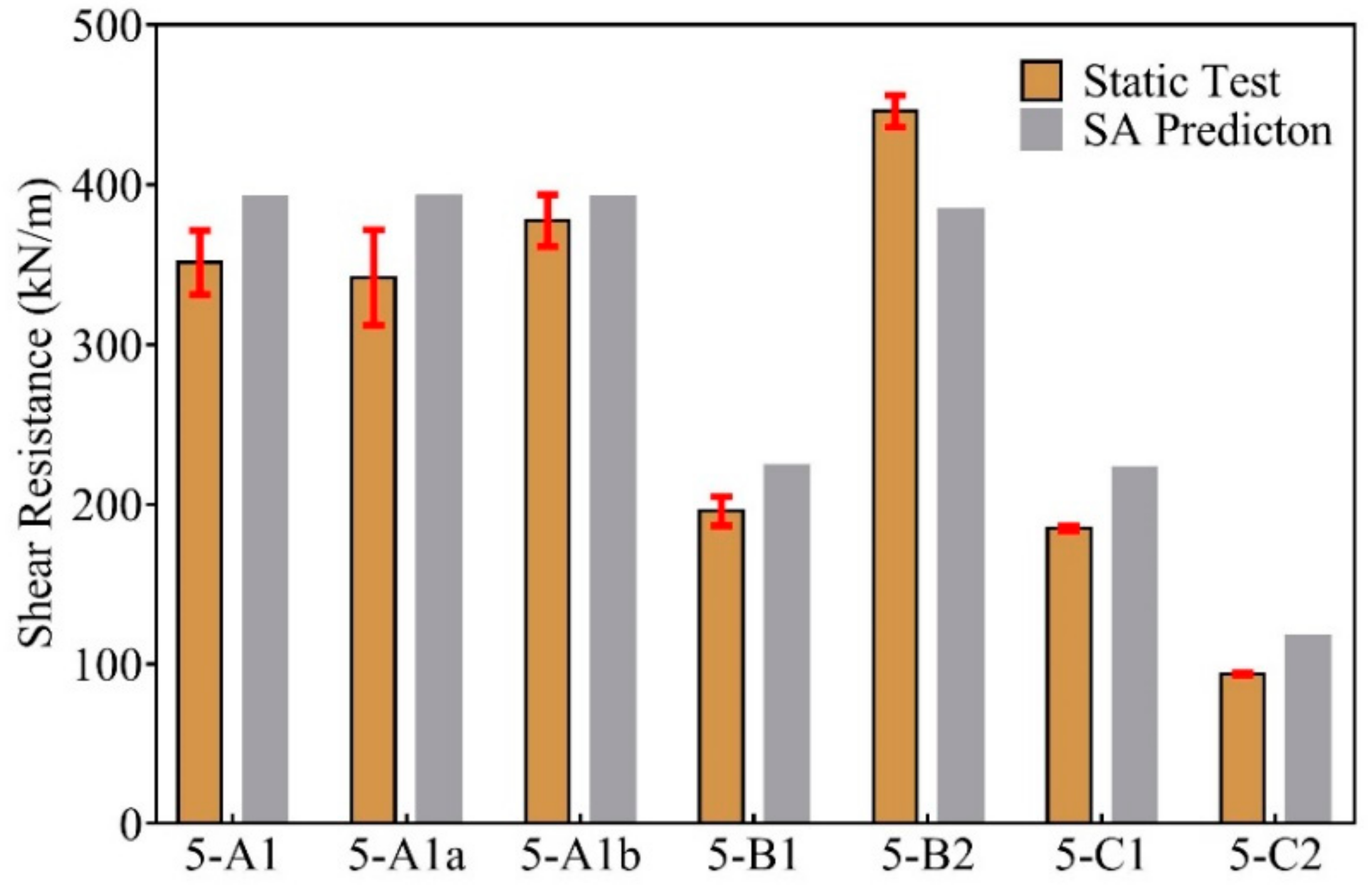
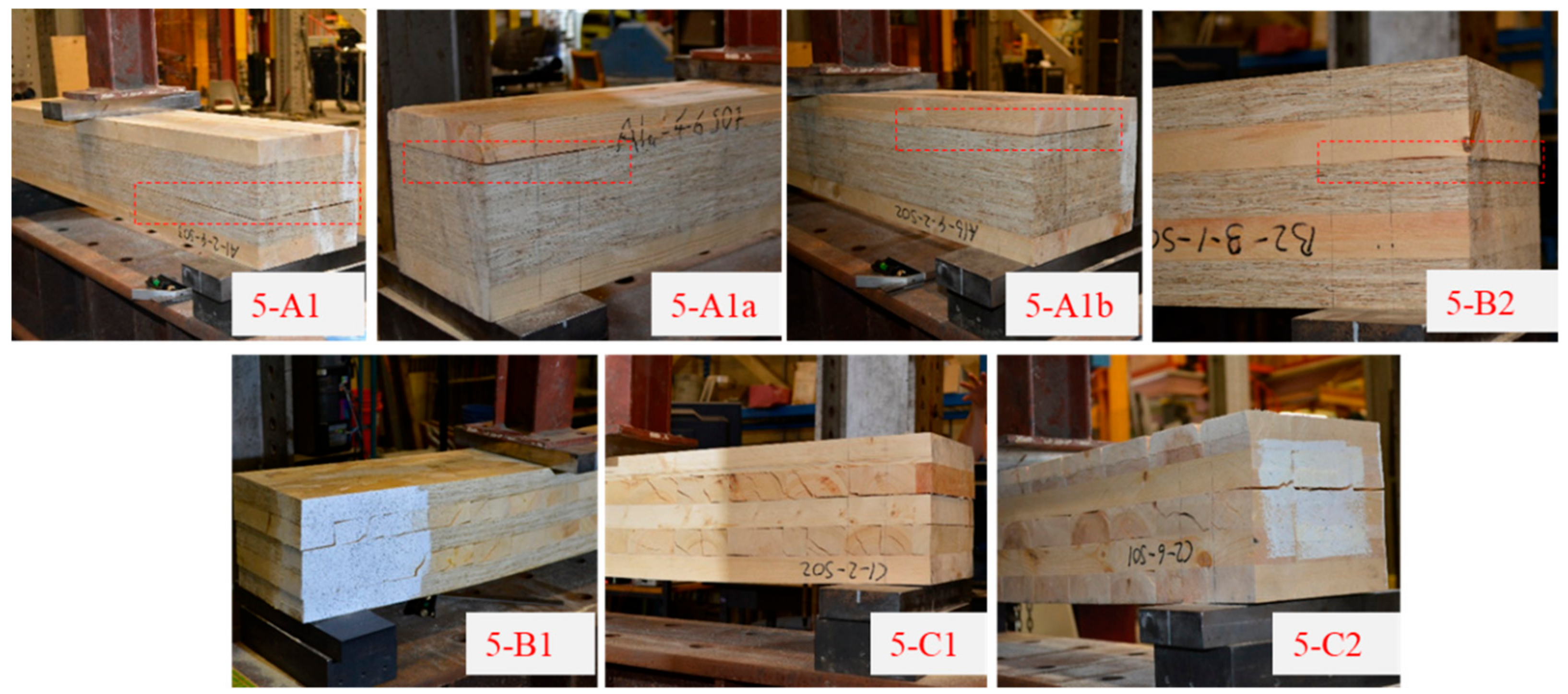
3.1. Shear Properties

The shear properties of all specimens are summarized in Table 3, which includes the shear resistance ( V r . s ) and dynamic shear stiffness ( G A e f f , d ) from static and modal tests, respectively, and the shear stress at failure ( τ ) and effective shear stiffness ( G A e f f , S A ) calculated based on shear analogy method. The failure modes are categorized as interfacial shear failure, which is the shear failure in the LSL layer close to the glue line, and rolling shear failure, which is the shear failure in the lumber layer perpendicular to grain.
As it can be seen in Table 3, the CLP group 5-B2 has the highest shear resistance and stiffness values among all the test groups. CLP groups 5-A1, 5-A1a, and 5-A1b have lower shear resistance and stiffness values than the CLP group 5-B2 but higher values than the remaining groups. CLP group 5-B1 and CLT group 5-C1 have close shear resistance values due to the same cross layers consisting of lumber pieces, and CLT group 5-C2 has the lowest values, as it represents the minor strength direction of a 5-layer CLT panel. The use of LSL in the core layers (5-A1, 5-A1a, and 5-A1b) and longitudinal layers (5-B2) with lumber parallel to grain in the cross layers lead to much higher shear resistance and stiffness values than those groups that involved layers of lumber perpendicular to grain in the cross layers (5-B1, 5-C1) or core layer (5-C2). Compared with the major strength direction of a regular CLT (5-C1), the mentioned test CLP groups had up to 142.5% higher shear resistance values (5-A1: 88.9%, 5-A1a: 85.8%, 5-A1b: 102.7%, and 5-B2: 142.5%) and up to 111.1% higher dynamic effective shear stiffness (5-A1: 80.3%, 5-A1a: 94.5%, 5-A1b: 70.1%, and 5-B2: 111.1%). This is due to the difference in planar shear properties between LSL and lumber. The mean planar (rolling) shear strength and modulus of No. 2 grade 2” by 4” western SPF lumber was reported to be 1.5 MPa and 73 MPa, respectively [10], while the mean planar shear strength and modulus of the LSL parallel to grain was measured to be 3.2 MPa and 462 MPa, respectively. Therefore, as expected, the calculated shear stress at failure in Table 3 agree well with the shear strength properties of the material that failed in the tests.
As shown in Figure 5, the measured shear resistances agree well with calculated counterparts for each group if the variation of wood material properties is taken into account. The difference between measured and calculated shear resistances varied from −12.7% to +25.4% (5-A1: 9.8% higher, 5-A1a: 13.0% higher, 5-A1b: 2.2% higher, 5-B1: 14.6% higher, 5-B2: 12.7% smaller, 5-C1: 20.7% higher, and 5-C2: 25.4% higher). The effective shear stiffness values of both CLP and CLT measured by modal tests are generally higher than those calculated by shear analogy method, as shown in Figure 6, though a mean rolling shear modulus of 120 MPa for lumber was used for the calculation. The difference between the measurement and prediction effective shear stiffness values are between 11.7% and 44.6% (5-A1: 16.8% higher, 5-A1a: 22.3% higher, 5-A1b: 11.7% higher, 5-B1: 27.5% higher, 5-B2: 22.4% smaller, 5-C1: 39.5% higher, and 5-C2: 44.6% higher). It is thought that the effective shear stiffness is under-estimated by the shear analogy method, especially for dynamic applications.
The failure modes observed during the short span shear tests are shown in Figure 7. As mentioned, typical rolling shear failures were found in the three groups with lumber perpendicular to grain as cross layers (5-B1, 5-C1, 5-C2), and the interfacial glue bond failure was observed in the other groups. Moreover, tension failures were noted for 5-A1 and 5-A1a groups (5-A1: 1 tension and 5 interfacial shear failures, 5-A1a: 2 tension and 4 interfacial shear failure failures). Within group 5-B2 one tension failure were recorded, the other five specimens failed due to interfacial shear failure.

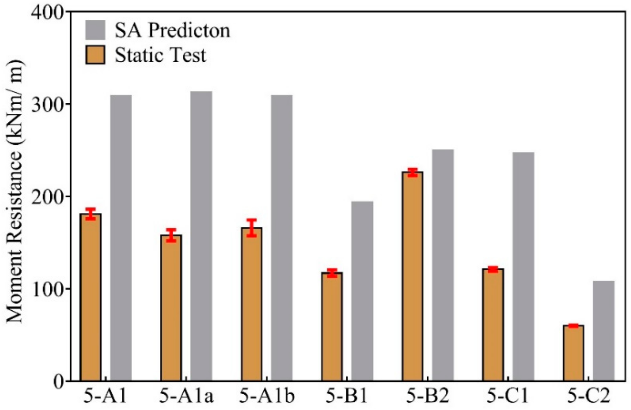
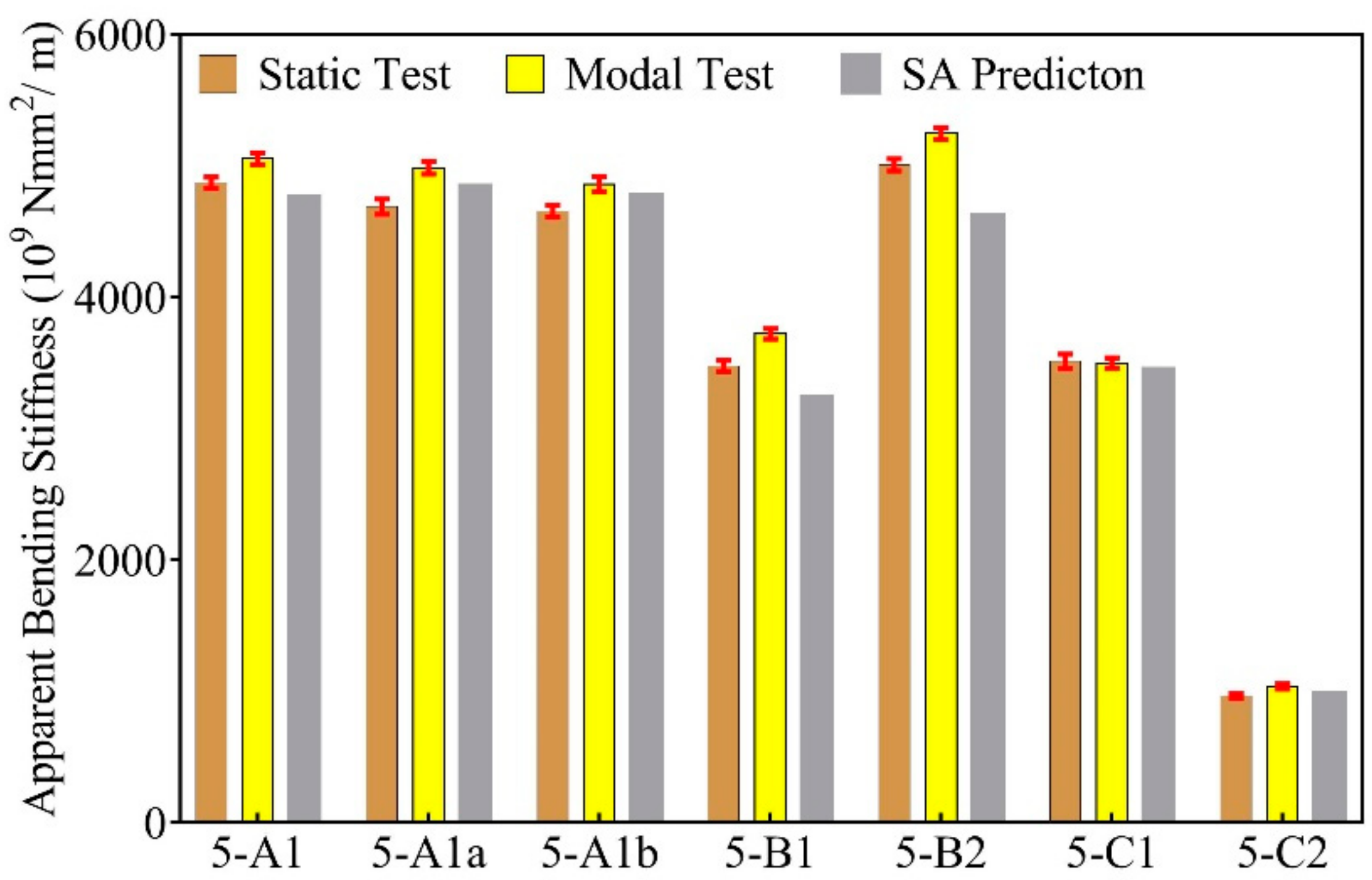
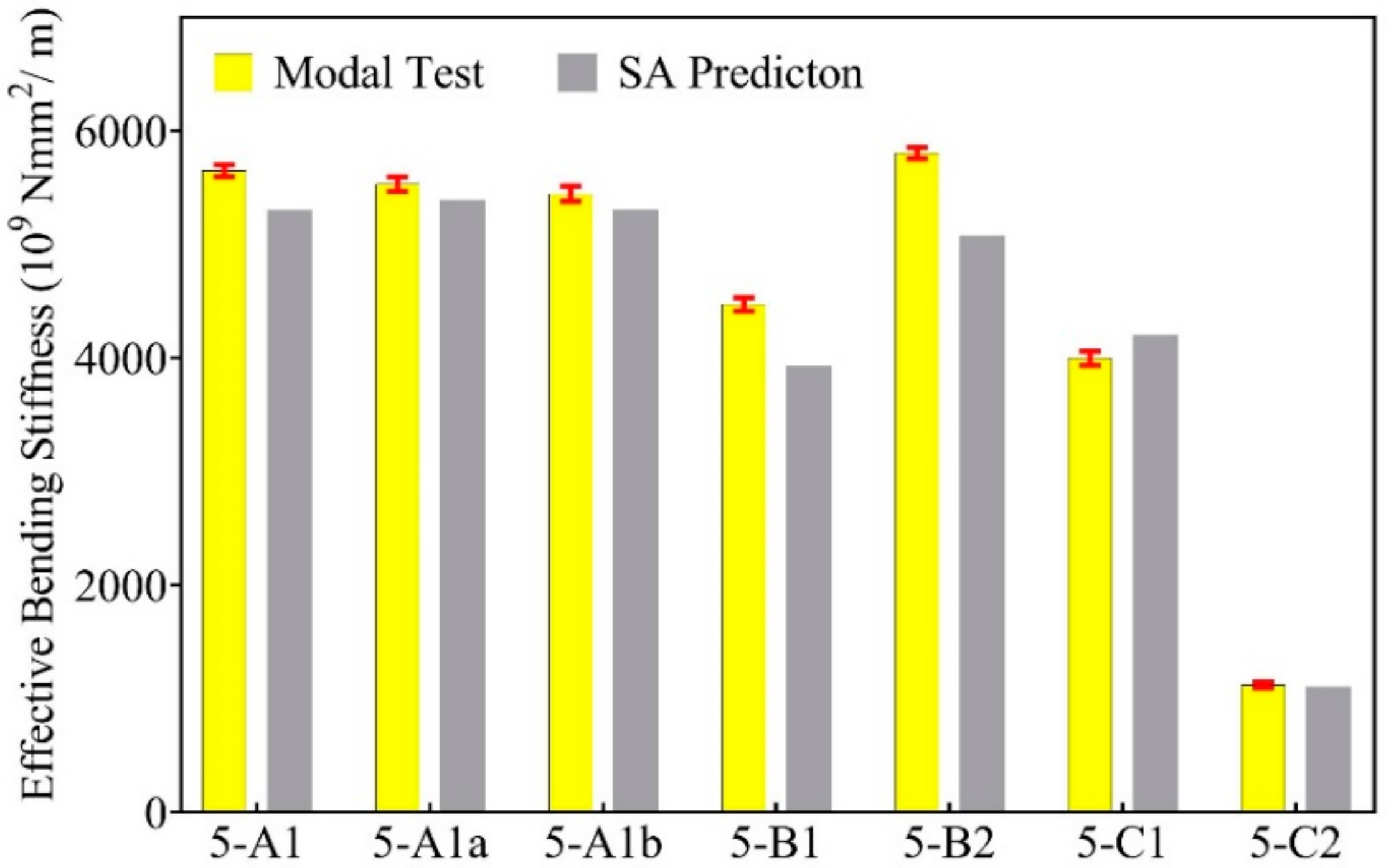
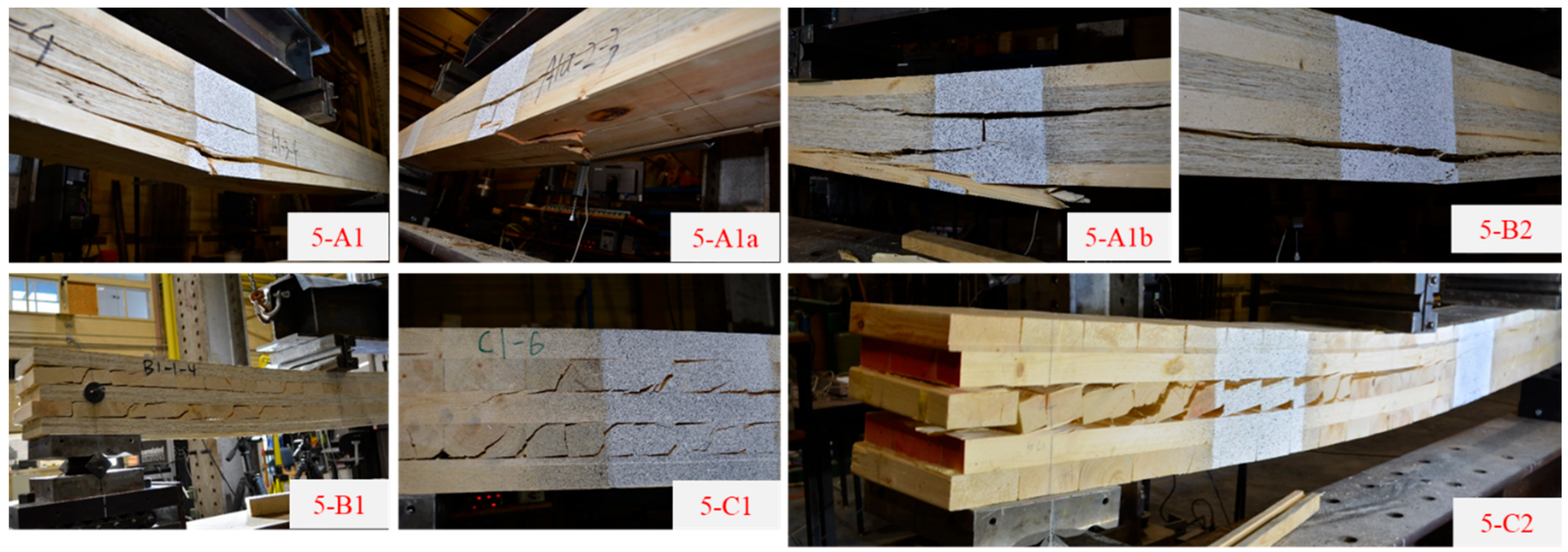
3.2. Bending Properties

The bending properties including moment resistance and bending stiffness values obtained, from both measurements and predictions, are listed in Table 4. The failure modes are categorized as tension failure of the bottom layer of MTPs, and rolling shear, which is the shear failure in the cross-lumber layer.
As seen in Table 4, similar to the trend in shear properties, the measured bending properties of CLP group 5-B2 outperform other MTP groups, especially for the bending moment resistance. The higher bending moment resistance of 5-B2 is attributed to the higher tensile strength of LSL (36.5 MPa) compared with lumber (30.2 MPa). Compared with the bending test values of CLT (5-C1), CLP groups 5-A1, 5-A1a, 5-A1b, and 5-B2 with LSL layers parallel to the length direction of the beam show increased bending moment resistance and apparent bending stiffness values to different extents (5-A1: 49.6% & 38.7%, 5-A1a: 30.6% & 33.5%, 5-A1b: 37.2% & 32.6% and 5-B2: 86.8% & 42.6%). CLP group 5-B1 shows very similar values to CLT (5-C1). The increase is due to two reasons. First, LSL has higher shear strength and modulus in the parallel to grain direction than the rolling shear strength and modulus of lumber although the MOE of LSL and lumber used in this study are close to each other. Second, all the longitudinal and transverse layers in CLP groups of 5-A1, 5-A1a, 5-A1b, and 5-B2 have laminations parallel to gain. The intended parallel orientation of all layers can increase the allowable span if such products are used as one-way floor systems. Moreover, due to the high bending and shear properties of SCL in the minor strength direction, two-way mechanical behavior can also be achieved for 5-layer CLP.
The apparent bending stiffness measured by modal tests agrees well with the values obtained from static bending tests with a mean difference less than 7.7%. The good correlation between the values measured by both methods is illustrated in Figure 8. Thus, the modal test can be used as an alternative method to evaluate the apparent bending stiffness of MTP beam specimens. The apparent bending stiffness based on Euler beam theory includes the effect of shear deformation, while the evaluated effective bending stiffness based on Timoshenko beam theory does not, which enables the separation of effective shear stiffness and the verification of effective bending stiffness calculated by shear analogy method. The effective bending stiffness obtained from modal tests is between 8.2% to 20.2% higher than the apparent bending stiffness obtained from modal tests depending on the layups of MTPs. The effective bending stiffness and shear stiffness obtained by modal test can be used for applications where the transverse shear deformation should be accounted, or the natural frequencies of higher vibration modes are of interest.
The comparison among static bending tests, modal tests, and shear analogy predictions are presented in Figure 9, Figure 10 and Figure 11. The shear analogy method predicts lower but close apparent and effective bending stiffness values and much higher moment resistance values than their measured counterparts. As shown in Figure 9, except for CLP group 5-B2, all groups have a much smaller measured moment resistance values than their predicted values. It should be noted that the bending strength values of LSL and lumber were used for the calculation of moment resistance in Equation (9). However, for 5-B1, 5-C1, and 5-C2, they had rolling shear failure in the cross layers. It is no wonder that the predicted moment resistance values are much higher than their measured ones. For 5-A1 series and 5-B2, the discrepancies can be explained by the increased uniformity of tensile stress distribution in the bottom layer. For a 5-layer layup where all layers have the same thickness, the minima tensile stress is about 65% of the maximum in the layer, which can be examined from the trapezoid stress distribution in the layer. Therefore, the specimens have a higher possibility of tension failure in the layer when the stress level exceeds the tensile strength of the material rather than bending strength, which is usually governed by the tensile strength of the outmost fibers. Moreover, the bending strength of wood materials is known to be higher than its tensile strength if the test specimen is of structural size [16,17]. The average bending and tensile strength values are 56.2 MPa and 30.2 MPa for lumber, and 43.2 MPa and 36.5 MPa for LSL, respectively. The average bending-to-tensile strength ratios in this study are 1.86 for lumber and 1.18 for LSL, respectively. Therefore, the calculated moment capacity based on bending strength is higher than what was previously measured. It can also be seen that the CLP group 5-B2 with tension failure in LSL bottom layers has smaller differences between measured and calculated moment capacity values due to the smaller bending-to-tensile strength ratio than that of lumber.
The typical failure modes of all the 5-layer MTP specimens are presented in Figure 12. Simple tension failure in the bottom layer of lumber was observed in groups 5-A1, 5-A1a, and 5-Ab, particularly around a knot. Simple tension failure in the bottom layer of LSL was seen in group 5-B2. Interfacial shear failure was the secondary failure after tension in the groups mentioned above. There was also no primary shear failure in the cross layers in the groups mentioned above. Typical rolling shear failure was found in the lumber cross layers in groups 5-B1, 5-C1, and 5-C2. No mixed failure modes were found within each group.

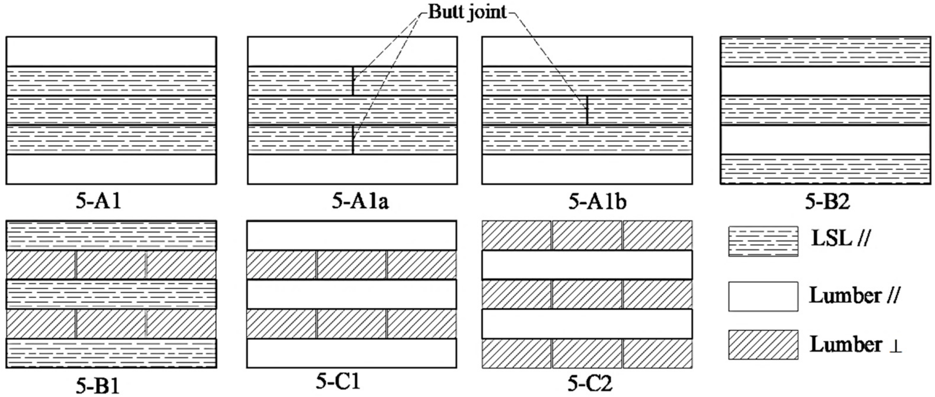
3.3. Effect of Layup and Butt Joint on the Mechanical Properties of CLP

The five CLP groups can be divided into three types based on their layups, the 5-A series (5-A1, 5-A1a, and 5-A1b), 5-B1, and 5-B2. With the mechanical properties of five groups of CLP presented in the above sections, it is evident that 5-B1 has the lowest mechanical properties values due to the cross layers of lumber perpendicular to grain. However, the 5-A series and 5-B2 both have their advantages. The 5-A series have no gaps in the middle layers (not counting the butt joints) and surface layers with lumber appearance. They can avoid rolling shear failure if both strength directions are considered. The 5-B2 group has slightly better mechanical performance in the major strength direction but would have rolling shear failure if the minor strength direction is considered. Future research should investigate the two-way behavior of both types.
It seems that the presence of butt joints has little influence on the mechanical properties of 5-A series based on the mean values listed in Table 3 and Table 4. One-way ANOVA analysis was conducted regarding shear resistance, moment resistance, and apparent bending from bending tests for further validation. The p-values at a confidence level of 95% of shear resistance, moment resistance, and apparent bending stiffness were 0.64, 0.085, and 0.015, respectively, which indicated the significance levels of the three parameters in 5-A1, 5-A1a, and 5-A1b. It is safe to conclude that the effect of butt joints on shear and moment resistance is negligible, while a significant difference is found among the apparent bending stiffness values among the three groups. A further Tukey pairwise comparison indicated that apparent bending stiffness of 5-A1 was significantly different from the other two groups. The different positions of butt joints between 5-A1a and 5-A1b did not influence their bending stiffness. However, the influence of butt joints can be affected by their spacing and may need to be further investigated. It might be beneficial to achieve slightly better bending performance by avoiding butt joints during fabrication.

4. Conclusions

A new category of mass timber panel designated as composite laminated panel (CLP) has been developed in this study. The mechanical properties of the CLP were evaluated through both static bending and modal tests. The applicability of the shear analogy method to predicting the mechanical performance of CLP was also examined. The following findings can be concluded.
(1)
The use of LSL as transverse layers in CLP can eliminate the typical rolling shear failure of CLT and increase shear resistance and stiffness, bending moment resistance, and stiffness compared with generic CLT.
(2)
The CLP with LSL and lumber being parallel to grain in all layers performs the best among all the CLP lay-ups investigated in this study.
(3)
The shear analogy method can be used to predict the mechanical performance of CLP including stresses at failure, effective bending and shear stiffness, and apparent bending stiffness. However, the prediction of moment resistance depends on actual failure mode and the related material strength values.
(4)
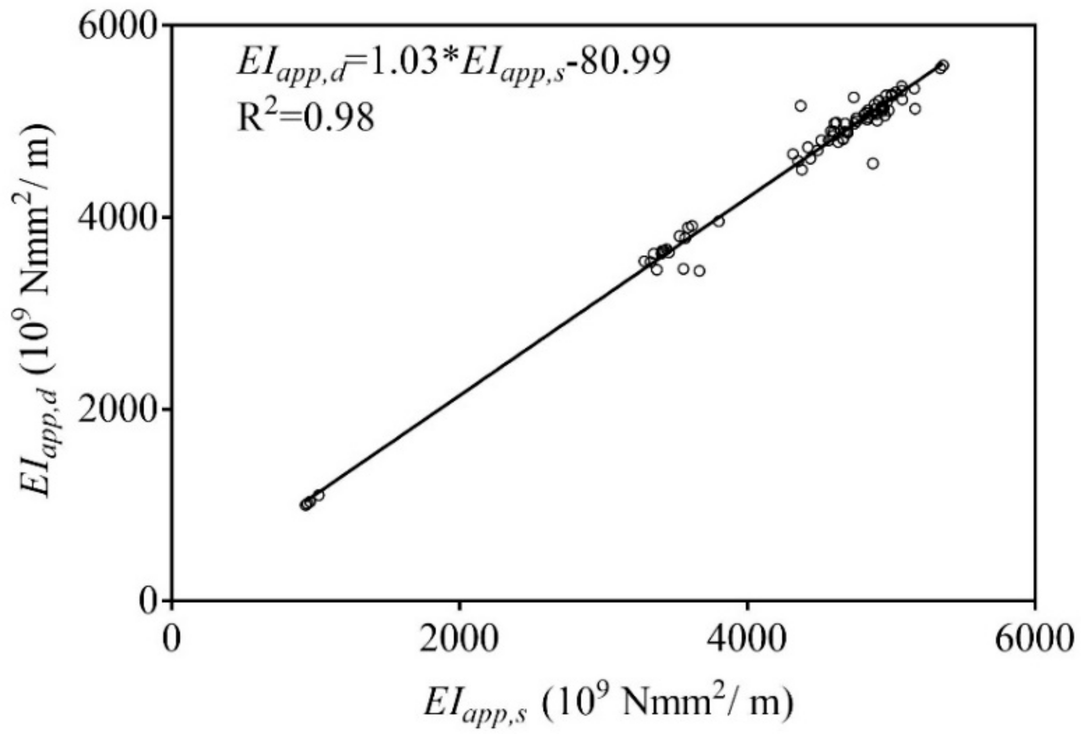
Modal test is effective in measuring the bending and shear stiffness of MTP with a good agreement with static test results.

Author Contributions

Conceptualization, Y.-H.C.; Methodology, J.Z. and J.N.; Validation, J.Z. and J.N.; Formal Analysis, J.Z. and J.N.; Investigation, J.Z. and J.N.; Resources, Y.-H.C.; Data Curation, J.N.; Writing-Original Draft Preparation, J.Z.; Writing-Review & Editing, J.N and Y.-H.C.; Visualization, J.Z.; Supervision, Y.-H.C.; Project Administration, Y.-H.C.; Funding Acquisition, Y.-H.C.

Funding

This research was funded by Natural Sciences and Engineering Research Council of Canada Industrial Research Chair in Engineered Wood and Building Systems program grant number [IRC500897-16] and Alberta Innovates [BFR-016-002].

Acknowledgments

In-kind support from Tolko Industries Ltd. and Henkel is acknowledged.

Conflicts of Interest

The authors declare no conflict of interest.

References

  1. Brandner, R.; Flatscher, G.; Ringhofer, A.; Schickhofer, G.; Thiel, A. Cross laminated timber (CLT): Overview and development. Eur. J. Wood Wood Prod. 2016, 74, 331–351. [Google Scholar] [CrossRef]
  2. Zhou, J.; Chui, Y.H.; Gong, M.; Hu, L. Elastic properties of full-size mass timber panels: Characterization using modal testing and comparison with model predictions. Compos. Part B Eng. 2017, 112, 203–212. [Google Scholar] [CrossRef]
  3. Brandner, R.; Dietsch, P.; Dröscher, J.; Schulte-Wrede, M.; Kreuzinger, H.; Sieder, M. Cross laminated timber (CLT) diaphragms under shear: Test configuration, properties and design. Constr. Build. Mater. 2017, 147, 312–327. [Google Scholar] [CrossRef]
  4. APA—The Engineered Wood Association. Standard for Performance-Rated Cross-Laminated Timber; ANSI/APA PRG 320; APA—The Engineered Wood Association: Tocama, WA, USA, 2018. [Google Scholar]
  5. Wang, Z.; Gong, M.; Chui, Y.H. Mechanical properties of laminated strand lumber and hybrid cross-laminated timber. Constr. Build. Mater. 2015, 101, 622–627. [Google Scholar] [CrossRef]
  6. Davids, W.G.; Willey, N.; Lopez-Anido, R.; Shaler, S.; Gardner, D.; Edgar, R.; Tajvidi, M. Structural performance of hybrid SPFs-LSL cross-laminated timber panels. Constr. Build. Mater. 2017, 149, 156–163. [Google Scholar] [CrossRef]
  7. Chui, Y.H.; Gong, M.; Niederwestberg, J. Development of a Lumber-SCL Massive Timber Panel Product; Final Report #: WSTC2014-038; Wood Science and Technology Centre, The University of New Brunswick: Fredericton, NB, Canada, 2015. [Google Scholar]
  8. Zhou, J.; Niederwestberg, J.; Chui, Y.H. Development and Evaluation of 5-Layer Lumber-SCL Massive Timber Panel; Final Report; The University of Alberta: Edmonton, AB, Canada, 2017. [Google Scholar]
  9. ASTM. Standard Test Methods of Static Tests of Lumber in Structural Sizes; ASTM D198; ASTM International: West Conshohocken, PA, USA, 2010. [Google Scholar]
  10. ASTM. Standard Test Methods for Structural Panels in Planar Shear (Rolling Shear); ASTM D2718; ASTM International: West Conshohocken, PA, USA, 2006. [Google Scholar]
  11. Chui, Y.H.; Gong, M. Evaluation of Planar Shear Properties of Cross Layer in Massive Timber Panel; Final Report #: WSTC2013-015; Wood Science and Technology Centre, The University of New Brunswick: Fredericton, NB, Canada, 2015. [Google Scholar]
  12. Yee, H.W. Shear Strength of Canadian Softwood Structural Lumber. Master’s Thesis, The University of British Columbia, Vancouver, BC, Canada, 1995. [Google Scholar]
  13. Inman, D.J. Engineering Vibration, 4th ed.; Prentice Hall: Upper Saddle River, NJ, USA, 2008; pp. 538–540. ISBN 978-0-13-287169-3. [Google Scholar]
  14. Chui, Y.H. Simultaneous Evaluation of Bending and Shear Moduli of Wood and the Influence of Knots on these Parameters. Wood Fibre Sci. 1991, 25, 125–134. [Google Scholar] [CrossRef]
  15. Bogensperger, T.; Silly, G.; Schickhofer, G. Methodenvergleich Approximativer Nachweisverfahren für Brettsperrholz; Report #: MMSM 2.2.3 sfem_mat; Holz.Bau Forschungs GmbH, Institut für Holzbau und Holztechnologie, Technische Universität Graz: Graz, Austria, 2012. [Google Scholar]
  16. CSA. Engineering Design in Wood; CSA O86-14; CSA Group: Mississauga, ON, Canada, 2016. [Google Scholar]
  17. Forest Product Laboratory. Wood Handbook—Wood as an Engineering Material, Centennial ed.; Forest Products Laboratory: Madison, WI, USA, 2010; p. 182. [Google Scholar]
Figure 1. Cross sections of five-layer CLP and CLT in the length direction with different layups.
Buildings 08 00142 g001
Figure 2. A 5-A1a beam specimen with butt joints in the second and fourth layers.
Buildings 08 00142 g002
Figure 3. A beam specimen under modal testing.
Buildings 08 00142 g003
Figure 4. Short-span shear test setup (left) and third-point bending test setup (right).
Buildings 08 00142 g004
Figure 5. Comparison between measured and calculated shear resistance values.
Buildings 08 00142 g005
Figure 6. Effective shear stiffness of 5-layer MTPs by modal test and shear analogy method.
Buildings 08 00142 g006
Figure 7. Typical failure modes under short-span bending (shear) tests.
Buildings 08 00142 g007
Figure 8. Correlation of apparent bending stiffness measured by modal and static tests.
Buildings 08 00142 g008
Figure 9. Average moment capacity of 5-layer MTPs by bending test and shear analogy method.
Buildings 08 00142 g009
Figure 10. Apparent bending stiffness of 5-layer MTPs by bending test, modal test, and shear analogy method.
Buildings 08 00142 g010
Figure 11. Effective bending stiffness of 5-layer MTPs by modal test and shear analogy method.
Buildings 08 00142 g011
Figure 12. Typical failure modes under third-point bending tests.
Buildings 08 00142 g012
Table 1. Summary of the material properties of lumber and LSL.
MaterialIndexMC (%)Density (kg/m3)MOE (MPa)MOR (MPa)Shear Modulus (MPa)Shear Strength (MPa)UTS (N/mm2)
//////////
LumberCount181838386
Mean7.447010,494343 257.4656 3120 45 41.5 530.2
COV 13.1%6.4%15.5%23.9%20.1%
LSLCount2222464666666
Mean3.4644952041.74622013.22.136.5
COV 14.7%6.4%5.9%13.1%14.2%9.3%9.2%7.5%11.6%
Note: 1 coefficient of variation (COV), 2 based on 1/30 of MOE, 3 based on 1/16 of MOE, 4 based on [11], and 5 based on [12].
Table 2. Layup information of the panels and number of specimens for mechanical tests.
Group IDLayupOrientationNumber of PanelsBending SpecimensShear Specimens
DimensionCountDimensionCount
5-A1T-L-L-L-T//-//-//-//-//32743 mm (length) × 195 mm (width) × 184 mm (thickness)131200 mm (length) × 195 mm (width) × 184 mm (thickness)8
5-A1aT-L *-L-L *-T//-// *-//-// *-//4168
5-A1bT-L-L *-L-T//-//-// *-//-//4148
5-B1L-T-L-T-L//-⊥-//-⊥-//3126
5-B2L-T-L-T-L//-//-//-//-//3146
5-C1T-T-T-T-T//-⊥-//-⊥-//142
5-C2T-T-T-T-T⊥-//-⊥-//-⊥142
Note: * Layer contained a centered butt joint.
Table 3. Shear properties of 5-layer MTPs.
GroupShear Resistance (kN/m)Shear Stress at Failure (MPa)Shear Stiffness (106 N/m)Failure Mode
V r . s V r . S A τ G A e f f , d G A e f f , S A
5-A1351.4392.52.988.073.2Interfacial Shear
(5.7%)(7.0%)
5-A1a342.0393.02.894.973.7Interfacial Shear
(8.7%)(7.5%)
5-A1b377.7392.63.183.073.3Interfacial Shear
(4.3%)(5.5%)
5-B1195.7224.01.438.628.0Rolling Shear
(4.7%)(3.7%)
5-B2446.2384.33.6103.079.9Interfacial Shear
(2.2%)(4.3%)
5-C1184.8223.11.348.829.5Rolling Shear
(0.9%)(7.3%)
5-C293.9117.71.226.714.8Rolling Shear
(0.5%)(11.5%)
Note: number in brackets is COV; shear resistance and stiffness are based on a panel width of 1 m.
Table 4. Bending properties of 5-layer MTPs.
GroupMoment Resistance (kNm/m)Bending Stiffness (109 Nmm2/m)Failure Mode
M r , s M r , S A E I a p p , s E I a p p , d E I a p p , S A E I e f f , d E I e f f , S A
5-A118130948715053477356505292Tension
(10.3%)(3.1%)(3.2%)(3.3%)
5-A1a15831346884985485455315388Tension
(15.2%)(5.0%)(3.8%)(4.6%)
5-A1b16630946554861478154465301Tension
(19.3%)(3.6%)(4.4%)(4.6%)
5-B111719434773721324244733927Rolling shear
(10.2%)(4.1%)(3.7%)(4.5%)
5-B222625050085247462958045071Tension
(5.5%)(3.4%)(3.2%)(3.2%)
5-C112124735113499345639984195Rolling shear
(3.3%)(3.2%)(2.3%)(3.1%)
5-C260108964103898811231098Rolling shear
(2.4%)(3.7%)(3.8%)(4.7%)
Note: The values in the brackets are the coefficient of variation.

