Smart Solar-Powered LED Outdoor Lighting System Based on the Energy Storage Level in Batteries


Mechanical Engineering Department, Jordan University of Science and Technology, 22110 Irbid, Jordan
*
Author to whom correspondence should be addressed.
Buildings 2018, 8(9), 119; https://doi.org/10.3390/buildings8090119
Submission received: 4 July 2018
/
Revised: 23 August 2018
/
Accepted: 29 August 2018
/
Published: 31 August 2018
Abstract
:A novel smart solar-powered light emitting diode (LED) outdoor lighting system is designed, built, and tested. A newly designed controller, that continuously monitors the energy status in the battery and, accordingly, controls the level of illumination of the LED light to satisfy the lighting requirements and/or to keep the light “on” the longest time possible, has been developed. The use of such a reliable solar energy-driven lighting system, with maximum time when the light is “on”, will eliminate the sudden-death of light problem present in conventional photovoltaic (PV) outdoor lights and, therefore, will enhance the natural surveillance and feeling of safety in sustainable buildings and cities. Furthermore, the new smart control eliminates the overdischarge of the system battery and, thus, ensures a longer lifetime of the system battery. Experimental measurements on a system using a 30 W LED light showed that the operating hours of the new system reached 29.16 h (1750 min), while the operating hours for a similar conventional system were 20.86 h (1252 min). Thus, the new lighting system was demonstrated, securing more than 40% of operating hours than the conventional systems.
1. Introduction
Demand for energy increases more and more as the global population grows, and economies of the developing countries continue expanding and expected to be tripled by 2050. Nowadays, energy resources come from hydrocarbon fuel, which is a finite resource and considered as one of the main reasons for international conflicts [1]. Solar energy is one of the most attractive alternative energy resources for many countries, including oil-producing countries. However, the continuous increase in oil prices is forcing many countries to seek alternative sources of energy, for example, in countries like Jordan, the average daily solar radiation is between 5.5–7.5 kWh/m2, with sunshine duration of 3000 h per year [2]. Photovoltaic (PV) technology presents a practical solution for numerous power application problems in isolated areas, as well as in the center of the large cities. Stand-alone PV lighting systems are one of the most common applications of PV. Since using energy-efficient lighting is an important factor for sustainable development and energy strategies, the combination of high-efficiency PV with LEDs allows the release of stand-alone PV lighting systems that provide a practical energy-efficient solution for lighting systems [3].
Wu et al. [4] have presented and investigated the design of solar-powered LED roadway lighting using high power LED luminaries (100 W), and estimated the total cost of installations for a 10 km highway with two lanes. A comparison between LED lighting using solar power and grids, with traditional mercury lamps, regarding cost, found that 75% of energy can be saved by using LED lighting. Considering the payback and lifetime, LED lighting using solar power or grid power were found to be economically feasible. Since energy efficiency is a major concern in designing off-grid renewable energy systems, [5] have presented a characterization of the potential benefits of using LED lighting and conventional metal halide systems. They found that using LED luminaries is not a direct replacement for metal halide systems when higher levels of luminance are required, since LED light does not provide the same magnitude of illumination as metal halide. However, they presented collected illumination data that may be useful in designing a renewable energy-powered microgrid that uses multiple LED fixtures to illuminate an outdoor area to replace a conventional metal halide system.
Costa et al. [6] had suggested an autonomous street lighting system as an alternative for remote localities, such as roads and crossroads. The suggested lighting system was implemented in DC to present high efficiency and scotopic human sensitivity. Huang et al. [7] introduced a high-performance charge/discharge controller for a stand-alone solar LED lighting system. The introduced controller incorporates a near-maximum-power-point operation (nMPPO), pulse width modulation (PWM), battery charge control, and a PWM battery discharge control to drive the LED directly from the battery. A similar performance of maximum power point tracking (MPPT) was obtained with the introduced controller by proper matching between the PV module specifications and the battery. They performed a reliability test for the light decay of LED lamps, which showed that the light decay of PWM-driven LED was the same as that of constant-current-driven LED. Based on this result, the DC/DC converter was removed from the stand-alone solar system to eliminate the DC/DC conversion loss and cost. A simple design for a direct current (DC) regulator has been proposed by Fathi et al. [8], the proposed DC driver was implemented to solar LEDs lamp based on white diodes of phosphorus GaN, and it was applied in a PV stand-alone outdoor lighting system.
Energy saving has become a more and more important motivation in illumination, so that a need for light dimming arose to save energy, and became a must. Liu et al. [9] utilized a dimming control method by varying switching frequency in their dimmable electronic ballast. The interface circuit for analog dimming control had been analyzed and tested. The experimental results showed that the ballast could dim the power of high-pressure sodium (HPS) lamp from 33% to 100%, without acoustic resonance, and with an efficiency higher than 90.3% through the whole dimming range.
Recently, Kim and Park [10] introduced an alternative design for community street lighting by applying “Crime Prevention Through Environmental Design” (CPTED) concepts to enhance natural surveillance and feelings of safety. They compared these alternatives to existing lighting. Yoomak and Ngaopitakkku [11] developed an analysis of lighting quality for dry and wet road surfaces using the DIALux software, and made a comparison between high pressure sodium (HPS) and LED luminaires. Results show that the HPS luminaires can provide better average illuminance than LED luminaires, however, LED luminaires can achieve better overall visual and comfort performances, including energy saving, due to their light distribution efficiency. Campisi et al. [12] evaluated the feasibility of the redevelopment of public lighting of the municipality of Rome. The consideration of the study was to replace the conventional lamps with LED lamps. They focused on the factors that affect the project, like energy and maintenance cost. Based on real options used to evaluate the economic cost-saving of the project, they reported a reduction on the energy consumption and maintenance cost, lower emission of CO2 into the atmosphere, and positive effects on the street. Campisi et al. [13] discussed the techno-economic feasibility of replacing the traditional lamps in public lighting in Rome with LED luminaires. They reported, based on the possible energy saving and cost, that despite the cost of the LED luminaires, the use of LED technology is economically feasible.
Cucchiella et al. [14] investigated the economics of the photovoltaic energy systems with battery storage for residential areas. They concluded that the benefits of such systems are higher in countries that have high values of solar insolation, and suffer from an excessive energy cost and a strong dependence on imports. Furthermore, they reported several break-even points (BEPs) of the investments, at which the residential PV battery systems become economically viable.
Some solutions to enhance the energy efficiency of centralized lighting systems are recently proposed in the literature [15,16]. There are two main differences between the system proposed in this work and the work of Park et al. [15] and Elejoste et al. [16]. The system proposed in this paper applies to stand-alone single light, while the others apply to centralized systems. The second difference is that they worked on the demand management system, while in this work, the concentration was on the supply system (i.e., battery). For instance, Park et al. [15] proposed smart energy management to increase the power efficiency of the microgrid in conjunction with a distributed power supply. They used a centralized ESS (energy storage system) to examine the problems related to ESS in the smart grid. They applied a dispersion ESS and intelligent LED system to street light a city, and this system has low cost and generates an easy-to-manage IoT (internet of things) environment. This system reduced the installation cost by 33%, and made IoT-based intelligent energy, power monitoring of street light, and efficient energy possible within a microgrid.
On the other hand, Elejoste et al. [16] presented an intelligent streetlight management system based on LED lamps. This system aimed at minimizing the investment cost of traditional wired systems using wireless communication technologies, which needs civil engineering for burying of cables underground. The developed system helps to reduce the energy consumption. However, similar energy efficient demand resource management applied by [16] to the microgrid can be applied to the supply management system proposed by this work for the standalone system, to further enhance the energy savings.
In this paper, the stand-alone LED lighting system is considered. The newly designed system is equipped with a new controller, which is designed to enhance the efficiency of the system by the efficient use of the available energy in the battery. The smartness of the new system comes from the fact that the system main controller has continuous monitoring capabilities to measure the level of energy in the battery and, based on the state of charge of the battery, the controller decides the level of illumination of the light, to maximize the time when the light is on. Thus, the proposed system uses the diming technique to increase the time when the light is “on” based on the available energy in the battery.
2. The Main Concept of the New System
Conventional PV-lighting systems suffer from the sudden death of light. That is, once the level of energy in the battery reaches the minimum value of the depth of discharge (DOD) with a constant load, the light turns “off” suddenly. The newly proposed system will eliminate this problem by disconnecting the load when the level of energy in the battery reaches a certain level. The new system is composed of similar components to the conventional system, but the discharge controller is different. The main modes of operations of the new system are as follows:
- Charging Mode: During the day, the PV panels converts the solar energy into electrical energy and store it in the battery.
- Discharging Mode: During the night with no solar irradiation, the light requirements are triggered via a photosensor. The controller turns the light “on”. Energy is then withdrawn from the battery to turn the light load “on”. During this period, the controller keeps track of the voltage of the battery. If the battery voltage reduces below a certain threshold (which will be decided later) the dimmer starts to reduce the intensity of light. This will reduce the energy withdrawal from the battery. A further drop in the battery voltage requires more dimming of light, and then less withdrawal of energy from the battery and, thus, keeps the system “on”. Using the newly controller will increase the time of using the energy stored in the battery, and thus, the time of having the light “on”.
System Prototype
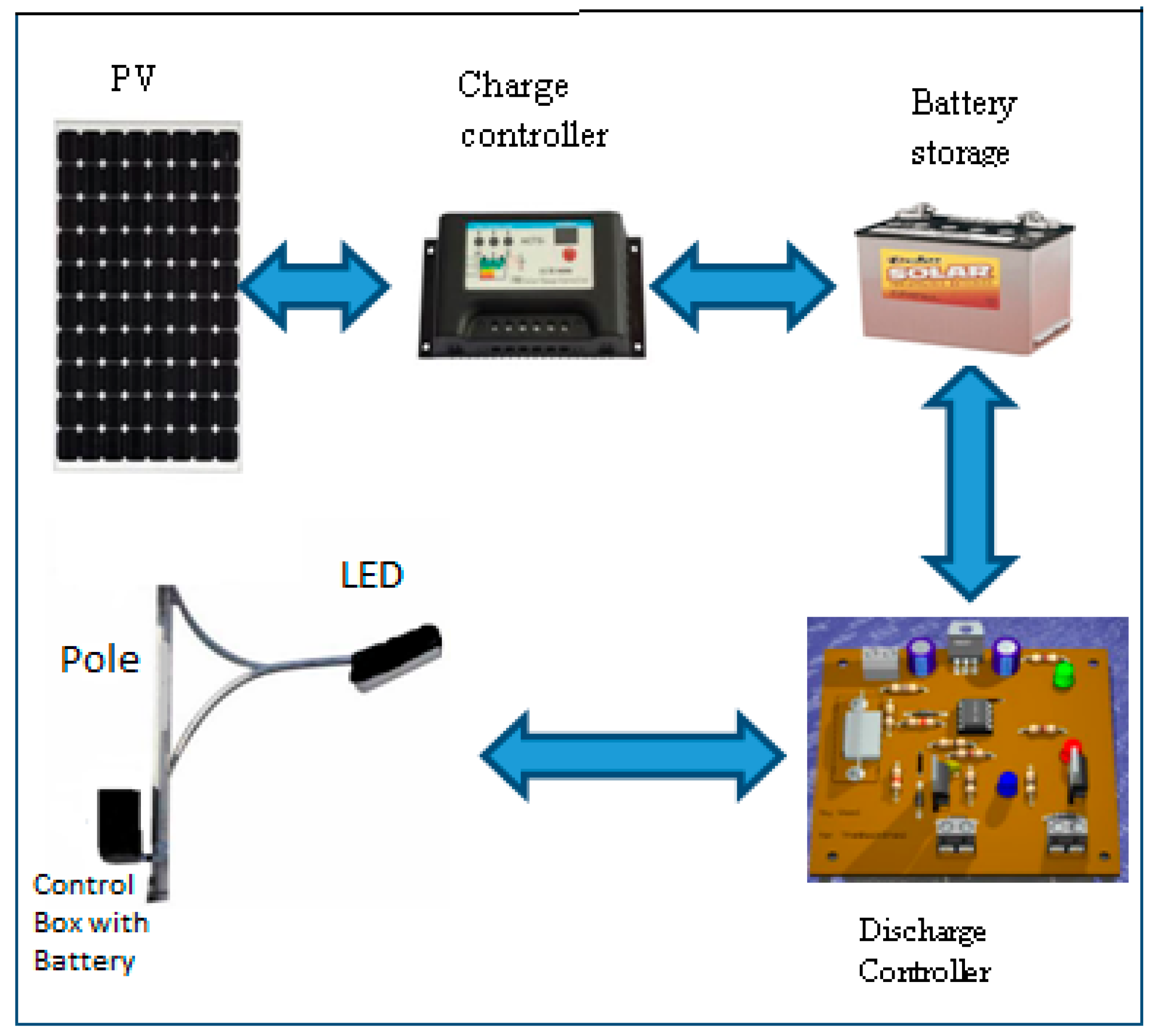
Although the proposed controller is built and tested on the PV-LED lighting system, it can be used in all standalone solar-powered systems. These systems are off-grid systems that can provide electrical power ranging from few milliwatts to kilowatts. Storage batteries are integrated with the stand-alone PV systems to supply the load with electricity at night or when the solar radiation is low (e.g., cloudy weather). Figure 1 shows a diagram of a typical stand-alone PV system for outdoor light. The system is composed of a PV panel, charge controller, battery, discharge controller, and a bulb.
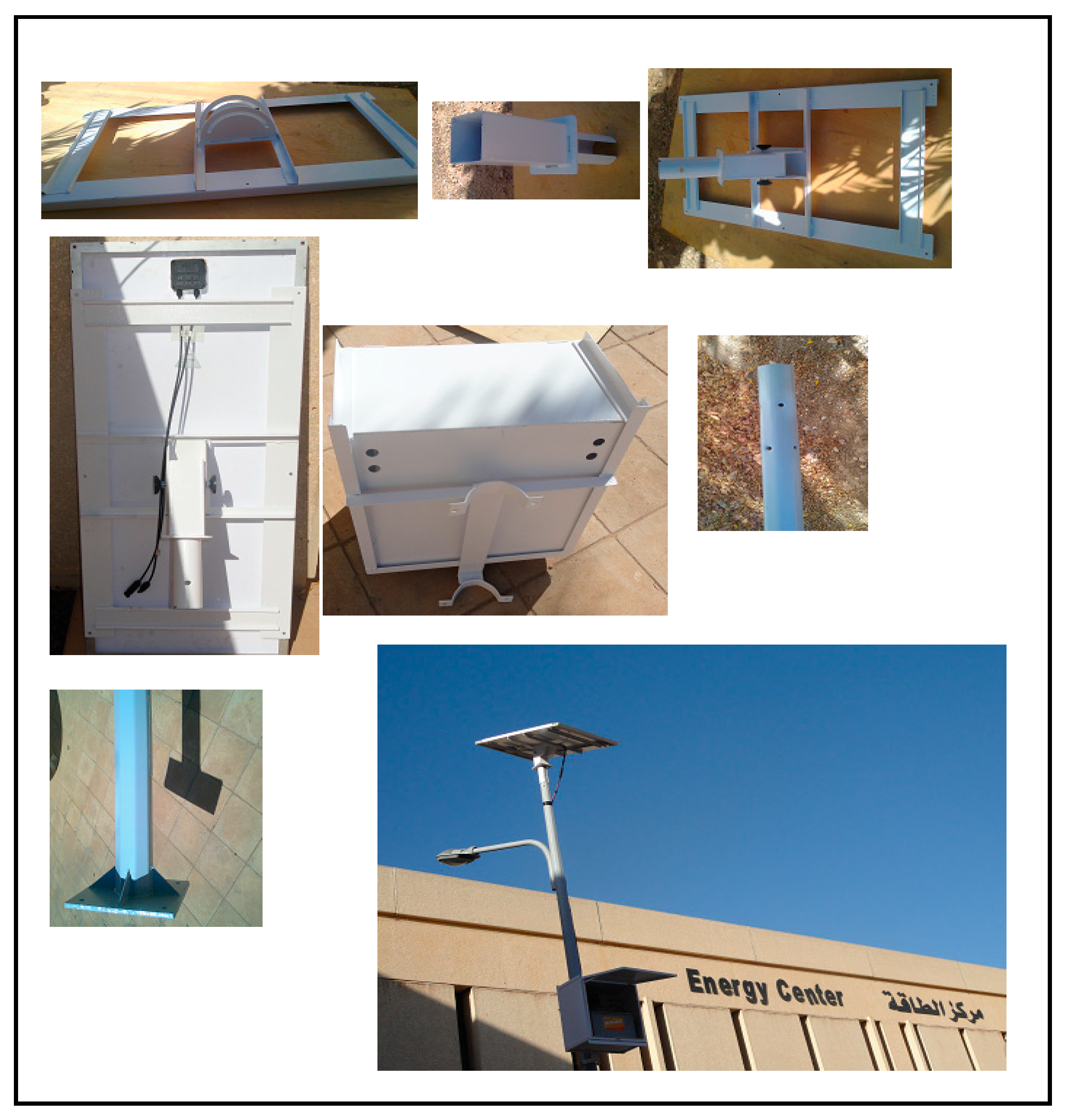
A prototype of the PV outdoor light was designed and built to carry out the experimental investigations on the performance of the new system, and compare it with conventional systems. Thus, the prototype is used twice: in the first time, it is used as a conventional system when the conventional controller is used, and for the second time, the system is equipped with the new controller. Figure 2 demonstrates the general assembly of the prototype which has been manufactured and assembled at Jordan University of Science and Technology (JUST).
Though this system will be used for experimentation purposes, it was designed and sized using the typical procedure of sizing real PV-LED lighting systems. Table 1 lists the general specifications of the prototype.
3. New Smart Battery Discharge Controller Design
The specific objective of this controller is to control the DC current supplied to the load (LED light) to maximize the time of using the available energy in the battery, and therefore, increase the system operating hours with no sun. This controller brings other benefits to the system, such as protecting the battery from being overdischarged, by turning the LED light off when the DOD of the battery reaches a certain level.
The new smart controller is composed of hardware and software to derive the controller. The controller was constructed using a low-cost programmable interface controller (PIC) microcontroller and simulated using Proteus ISIS® Professional package. The next section explains both hardware and software components.
3.1. Hardware Design
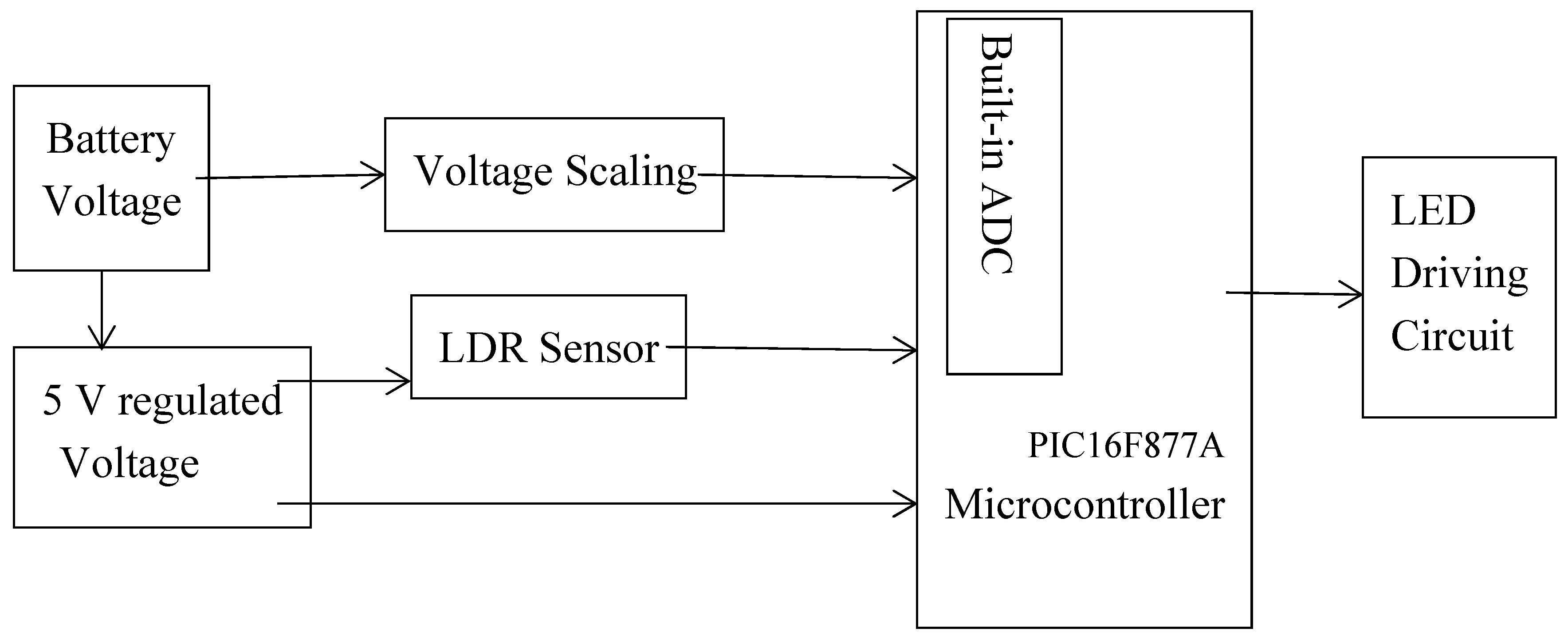
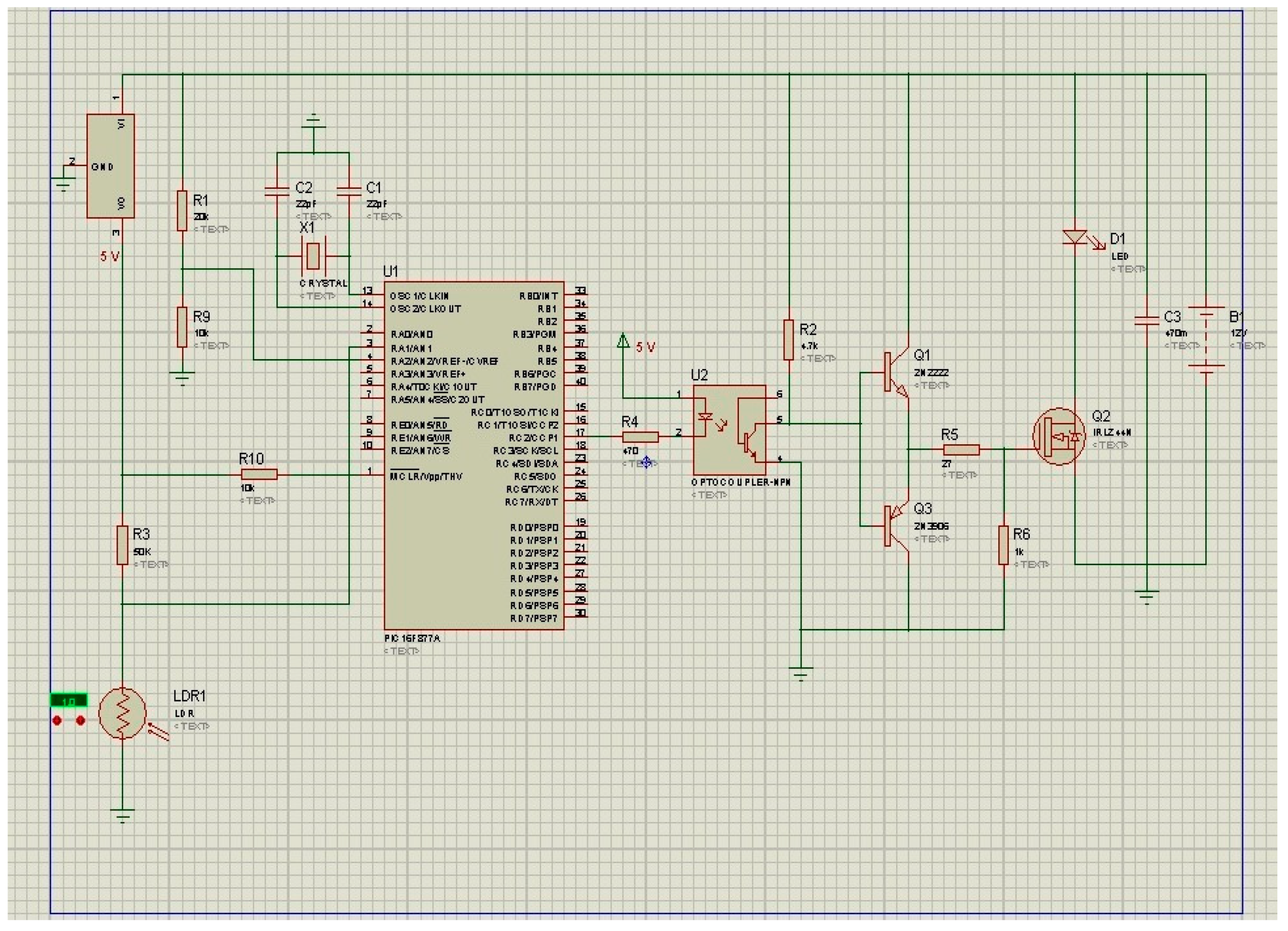
The controller is composed of five main parts (subsystems); the regulator, scaling voltage circuit, light-dependent resistor (LDR) sensor circuitry, microcontroller unit, and LED driving circuit. The analog signals received from sensors are converted into digital signals so they can be handled by the microcontroller. The block diagram of the overall controller is shown in Figure 3, while the complete schematic diagram for the complete controller is shown in Figure 4.
3.1.1. Power Supply Circuit
A 12–15 V battery is used as a power supply/store energy for the system. A 5V-L7805 positive voltage regulator is used to convert the voltage from the 12 V battery to 5 V to perfectly drive the microcontroller unit (MCU) and some analog ICs and sensor circuitry. The L7805 positive voltage regulator circuit is illustrated in Figure 5.
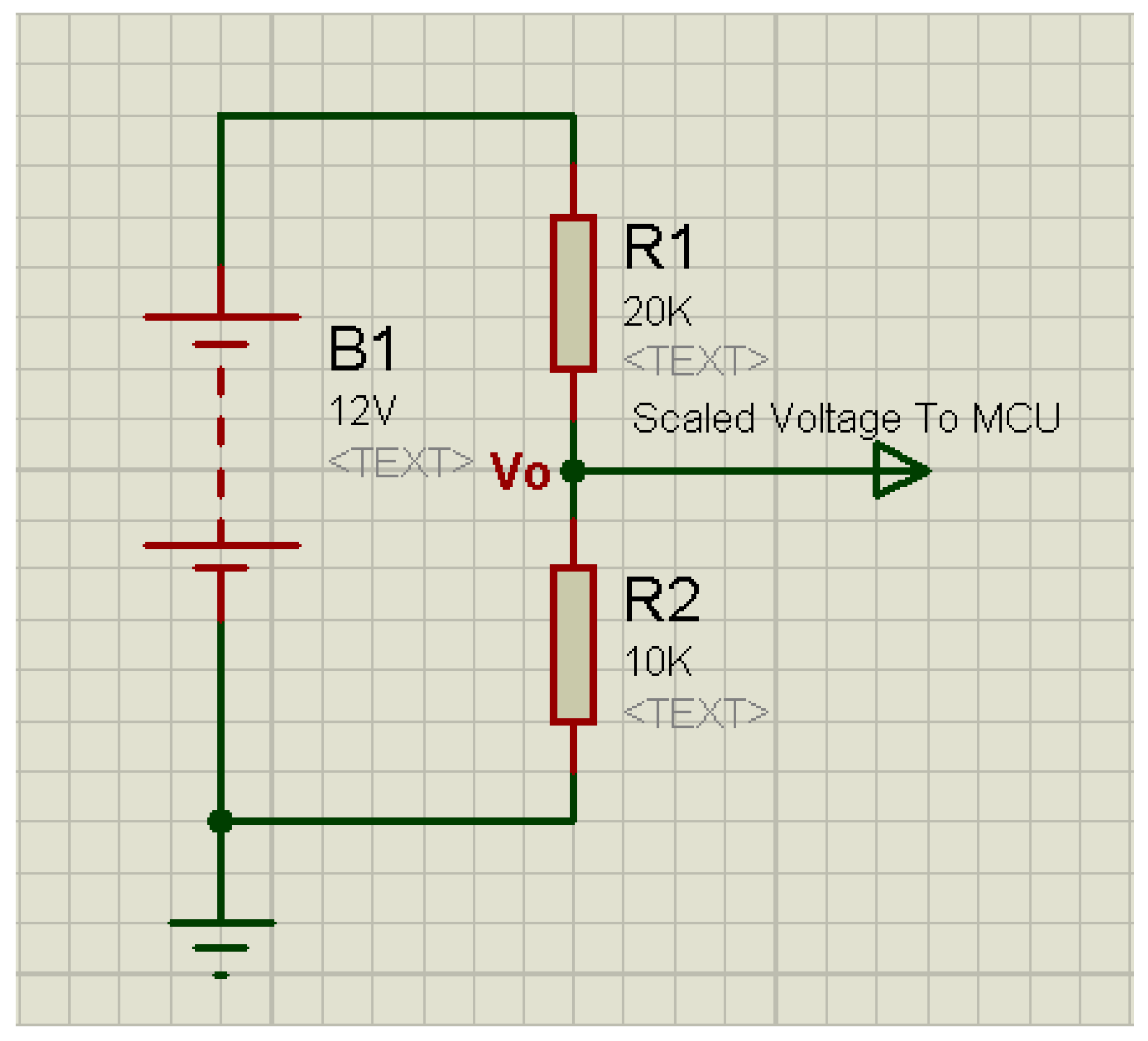
3.1.2. Voltage Scaling Circuit
The voltage divider circuit, shown in Figure 6, is used to scale the voltage measured from the battery to the level that can be handled by the microcontroller (from 15 V to 5 V). It is composed of R1 = 20 kΩ and R2 = 10 kΩ.
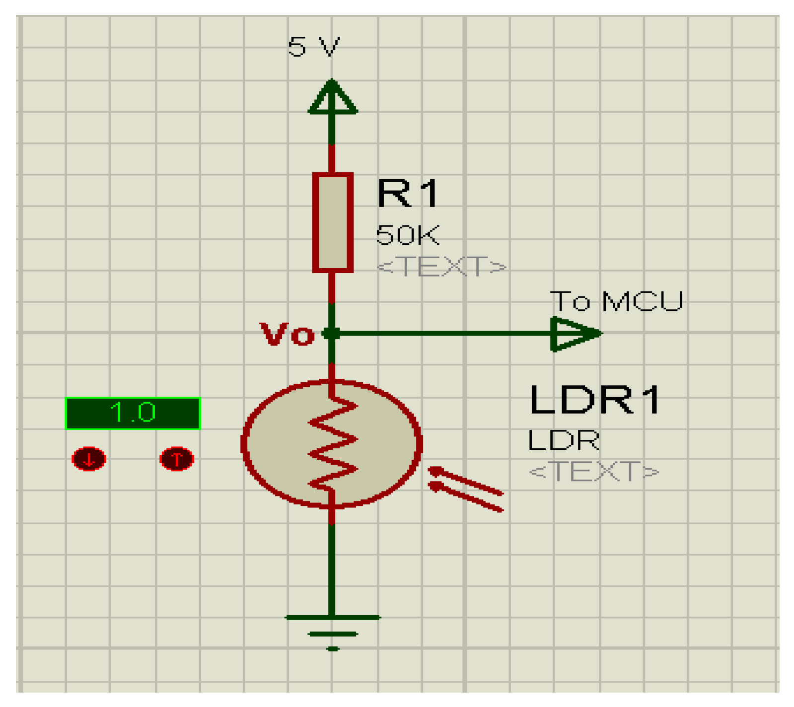
3.1.3. LDR Sensor Circuit
LDR is a resistor in which its value changes proportionally to the change of the incident light intensity falling on its surface. Its primary function here is to detect sunlight to trigger the main circuit of the system: “on” when there is no light, and “off” when sunlight is detected. LDR is made of a semiconductor material with high resistance, like cadmium sulfide (CdS) and cadmium selenide (CdSe). The LDR construction of reference [17] is used because it gives a minimum area and maximum length from CdS. It is fixed on the surface of the ceramic substrate in the form of zigzag wire.
The sensor is enclosed in a circular metallic or plastic case with two terminals, and covered with glass to protect it from moisture and dust. It is used in many applications like fire alarms, Lux meters, and outdoor light controllers. The block diagram of the sensor function and the schematic diagram for the sensor are shown in Figure 7 [18].
3.1.4. Microcontroller Unit
The programmable interface controller (PIC) (Microchip Technology Inc., San Jose, CA, USA) is a small computer on a single integrated circuit composed of a relatively simple central processing unit (CPU), timers, input/output (I/O) ports, and volatile memory (RAM) and non-volatile memory, ROM. Microcontrollers are, generally, designed for small and dedicated applications (not general purpose applications), such as automobile engine control systems, implantable medical devices, and remote controls. PIC16F877A microcontroller (Microchip Technology Inc., San Jose, CA, USA) from Microchip Technology is selected in this controller because it is a very popular MCU, due to its availability, low cost, and simplicity in design. The PIC16F877A is the superset MCU in the PIC16 family of MCUs, with most of the features, and it was the most high-end device in the PIC16 family until the new PIC16F887 was released. It is now recommended by Microchip for new designs. The differences between both the PIC16F877A and the PIC16F887 are limited [19,20,21].
Pulse width modulation (PWM) is used to generate signals of varying frequency and duty cycle. Two modules, CCP1 and CCP2, of PIC16F877A chip are designated to generate the PWM signals, which are used in this work to drive the LED.
The analog to digital converters (A/D) convert an analog input signal into a digital signal. The PIC16F877A chip has 8 input channels and a 10-bit analog-to-digital module. In this study, two input channels are used to read the analog signals produced by LDR sensors and battery voltage, and convert them to a digital signal. The connection of the MCU is shown in Figure 8.
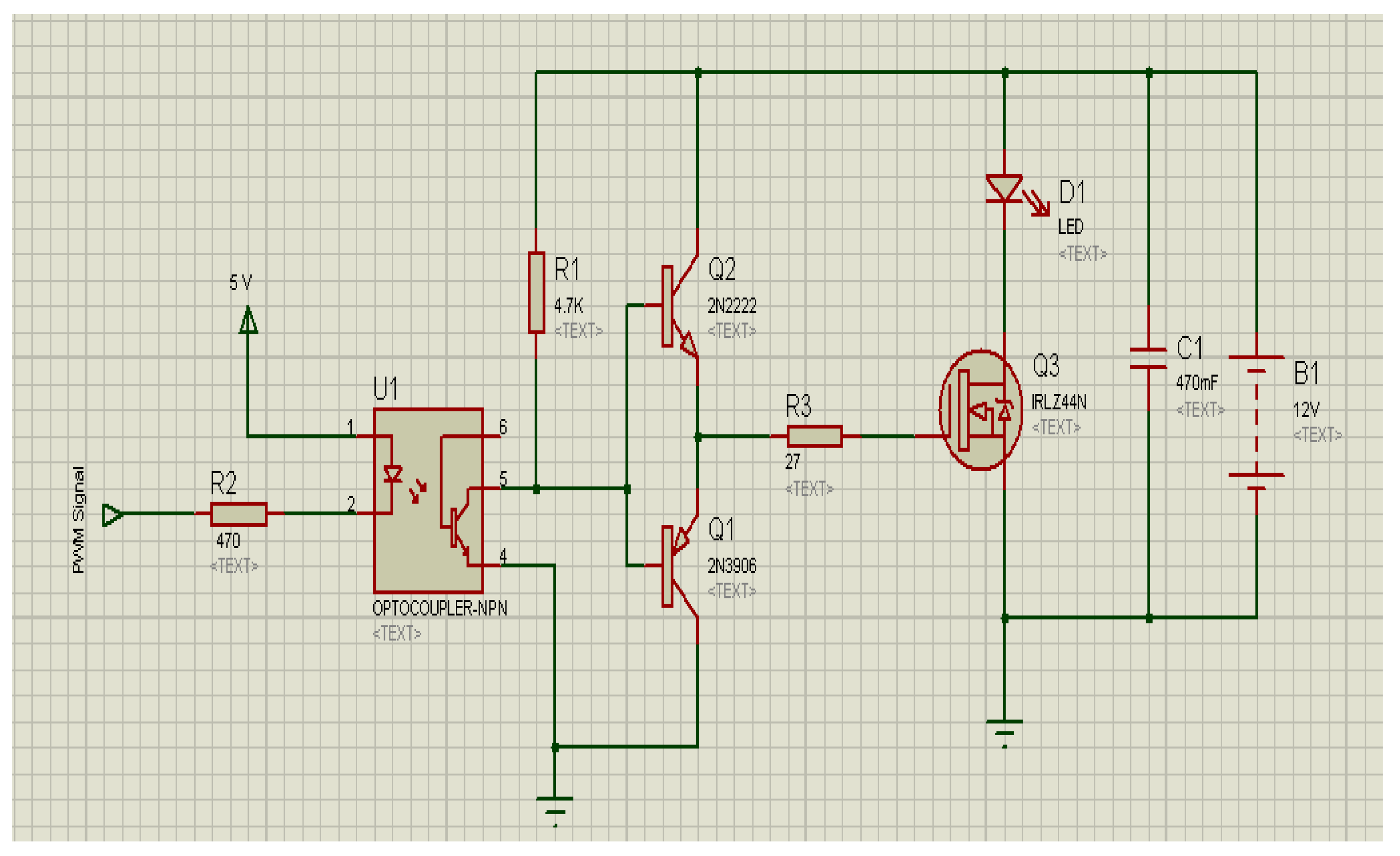
3.1.5. LED Driving Circuit by PWM
To control the level of the light intensity of the LED, the driving circuit of LED is designed as shown in Figure 9. It receives the PWM signal from the PIC16F877A chip at a varying duty cycle, to switch the lamp on and off. The driving circuit components are as follows:
- Optocoupler is an electronic device that transfers an electrical signal from one section of a circuit to another. It is composed of an infrared-emitting LED diode that is, optically, in line with a light-sensitive silicon semiconductor transistor, all enclosed in the same package [22]. It is used in this study to isolate the PIC16F877A chip circuit, which operates at 5 V, from the LED lamp driving circuit, which operates at 12 V.
- Push–pull output: It is an electronic circuit that uses a pair of active transistor Negative-Positive-Negative type NPN (denoted by Q2 in Figure 9) connected to a positive voltage and a Positive-Negative-Positive type PNP (Q1) connected to a negative voltage. This circuit is used to enhance turn on–turn off for the Metal-Oxide-Semiconductor Field-Effect Transistor (MOSFET) and suppress the current spikes to enhance the operating conditions for the PWM signals generated by the PIC16F877A chip [23,24].
- MOSFET: It is an important component in relatively high frequency, high-efficiency switching applications in the electronic circuits. In this study, it is used to drive the LED streetlight using the PWM signals. IRLZ44N n-channel MOSFET with 49 A drains current and very low on-resistance of 17.5 mΩ is used in the driving circuit, provided with a heat sink to protect it from being overheated. The schematic diagram of the LED driving circuit is showing in Figure 9.
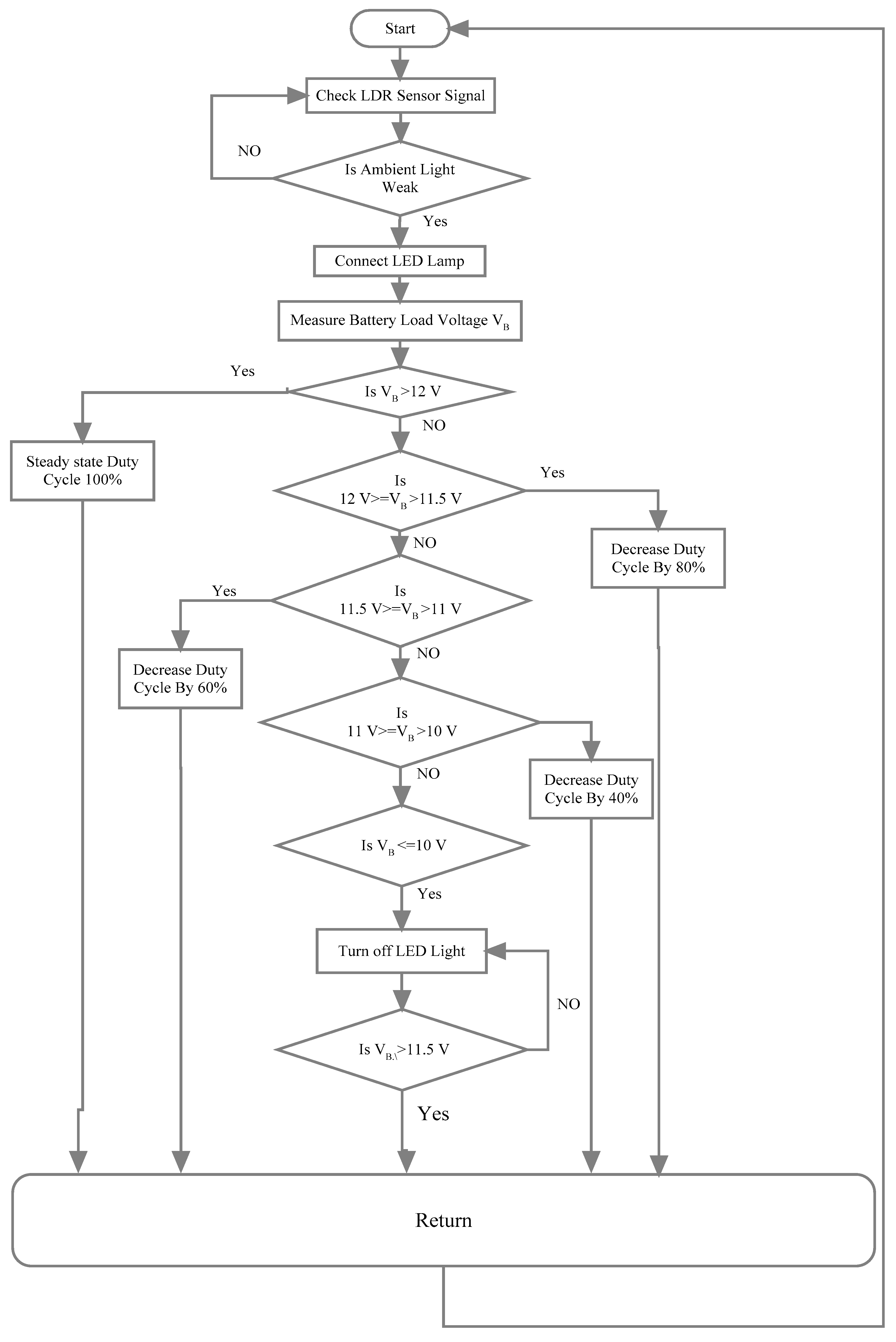
3.2. Controller Software
The discharge control of the outdoor light system algorithm was constructed and implemented based on battery load voltage. The programming language used to execute this algorithm was MikroBasic® pro (version 1, mikroElektronika, Belgrade, Serbia). Figure 10 shows the flowchart that describes the sequence of the algorithm. This algorithm was constructed according to the characteristics of the battery given by the manufacturer.
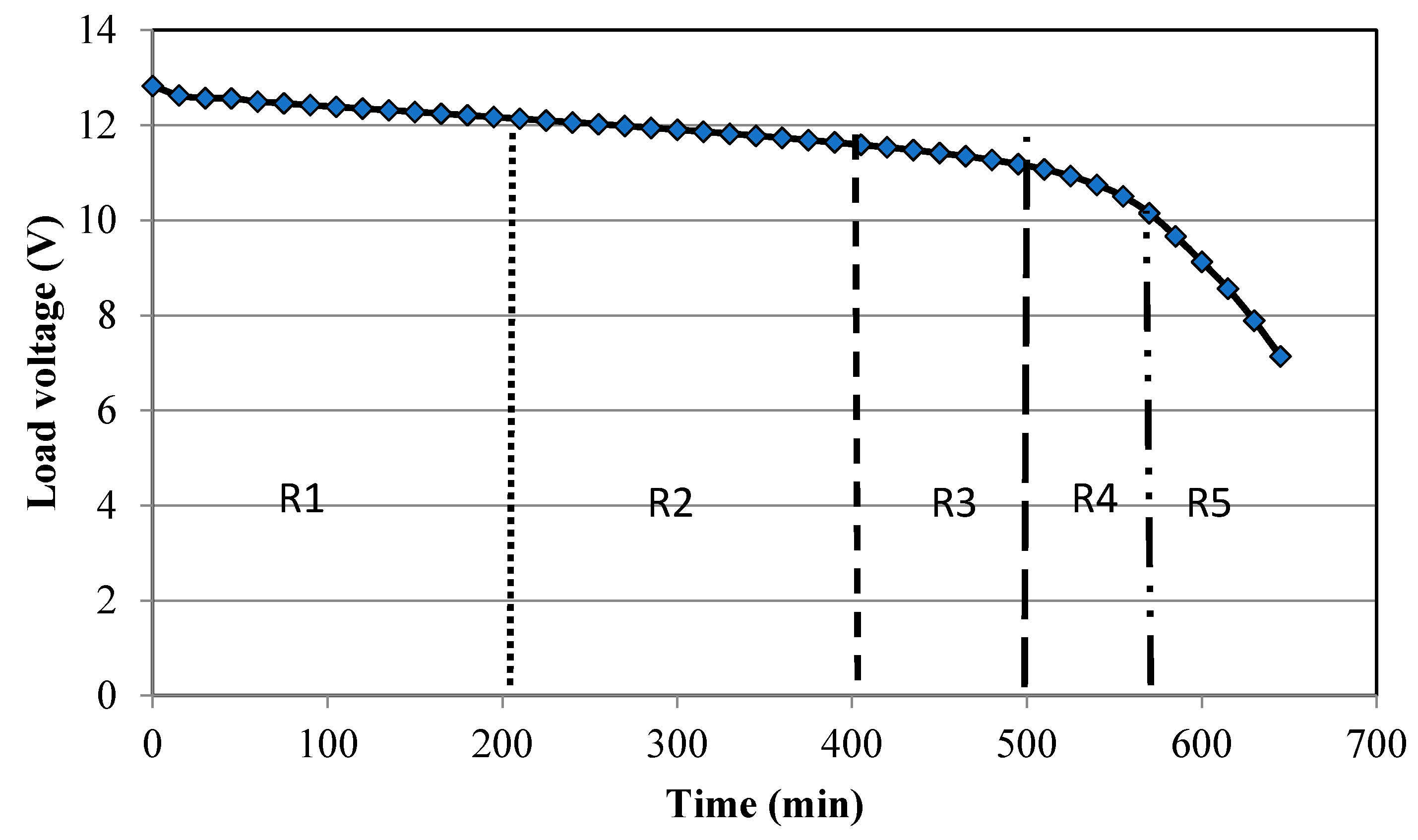
Long debates and literature reviews have been carried out to decide the best indicator to measure the level of energy in a battery. In this work, it is decided to use the “load voltage” as an indicator. This means that to decide the level of illumination of the light, read the battery voltage when the light is on, then make the decision. Reading open voltage sometimes gives a false indication because the chemical reaction inside the battery is active. To decide the levels of stepping down light levels for this system, the load voltage curve for the used battery (gel-acid) is experimentally measured as shown in Figure 11 using the experimental setup shown in Figure 12. The results are obtained by applying a constant load (LED light) to the gel-acid battery, while continuously measuring the battery voltage until the light turns off. Figure 11 also shows how battery discharge curve is used in this work, and it is divided into five regions. The first region (R1) when the load voltage (VB) is greater than 12 V, the second region (R2) when VB is less than or equal 12 V and greater than 11.5 V, the third region (R3) when VB is less than or equal 11.5 V and greater than 11 V, the fourth region (R4) when VB is less than or equal 11 V and greater than 10 V, and the fifth region (R5) when VB is less than or equal 10 V, which is the cutoff region. The Proteus ISIS® version 8, Labcenter Electronics Ltd., Yorkshire, England) Professional package was used to simulate the program before downloading it into the PIC16F877A chip.
4. Experimental Procedure
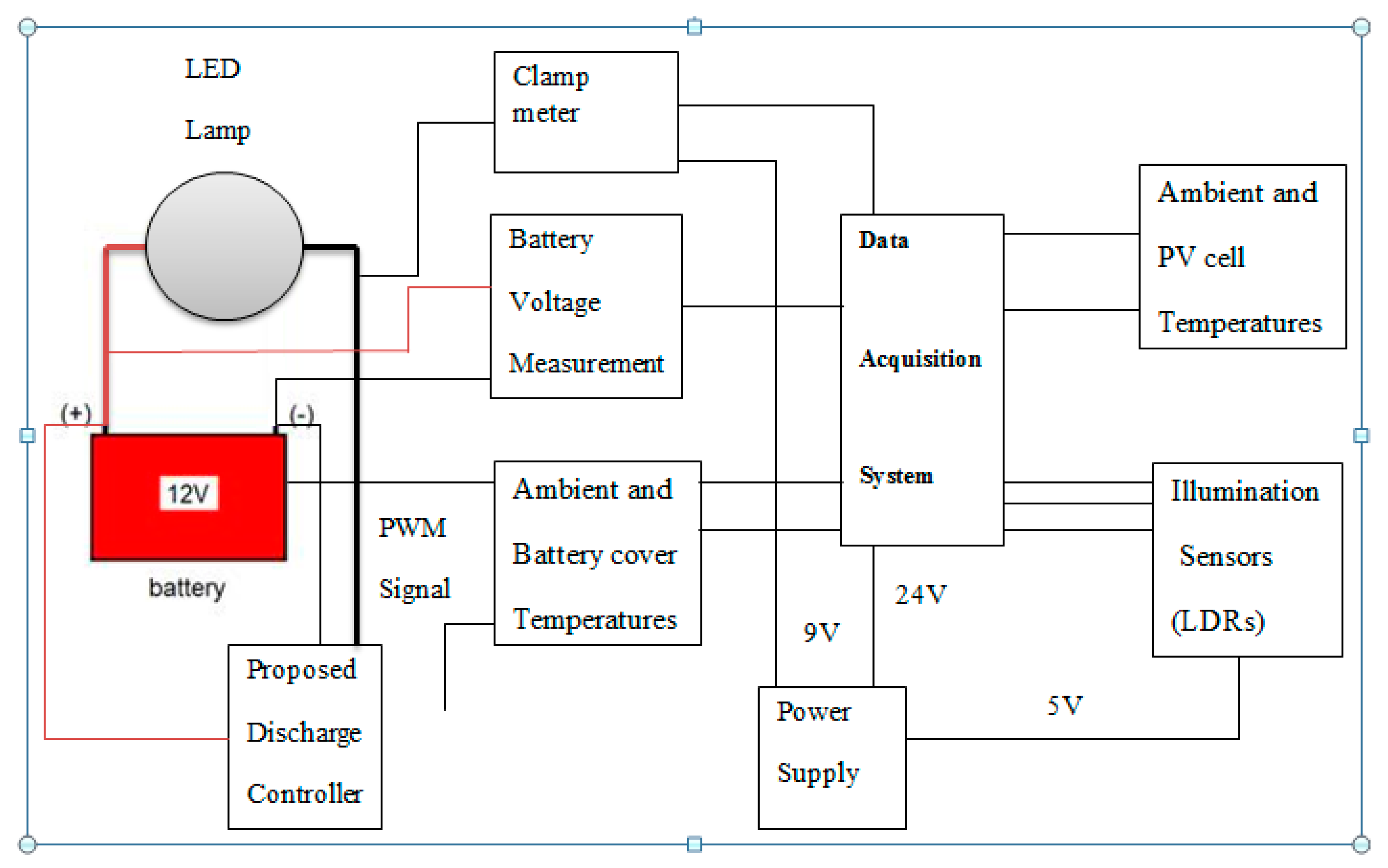
The following are the steps that have been followed during inquiring data from the system to evaluate the system performance. It should be noted that this experiment has been carried out inside the laboratory to ensure complete darkness and ensure that the only source of light is the LED bulb. The measurements of light intensity were taken using the LDR sensors and at different locations on the ground. The LED light is 6 m above the ground. All measured data were collected and stored in the computer using data acquisition system. At the beginning of each experiment, the battery was ensured to be fully charged. During the experimentations, many physical quantities were measured: DC current withdrawn from the battery, battery voltage, light intensity at different locations, and ambient temperature. The data acquisition system gets the data from sensors with a scan rate of one minute. Figure 12 shows a schematic diagram of the experimental setup.
Moreover, the experiment was repeated several times for two cases. In the first case, the newly designed controller is used, and in the other case, the conventional controller is used. The findings of each case are presented next.
5. Results
5.1. CASE 1: New Smart Controller
In this case, the battery is fully charged, then the PV is disconnected, and the LED lamp is turned on. During the daytime, the LED lamp is automatically turned off by the controller. Over the testing days, the readings of the sensors and battery load voltage were registered using a data acquisition system.
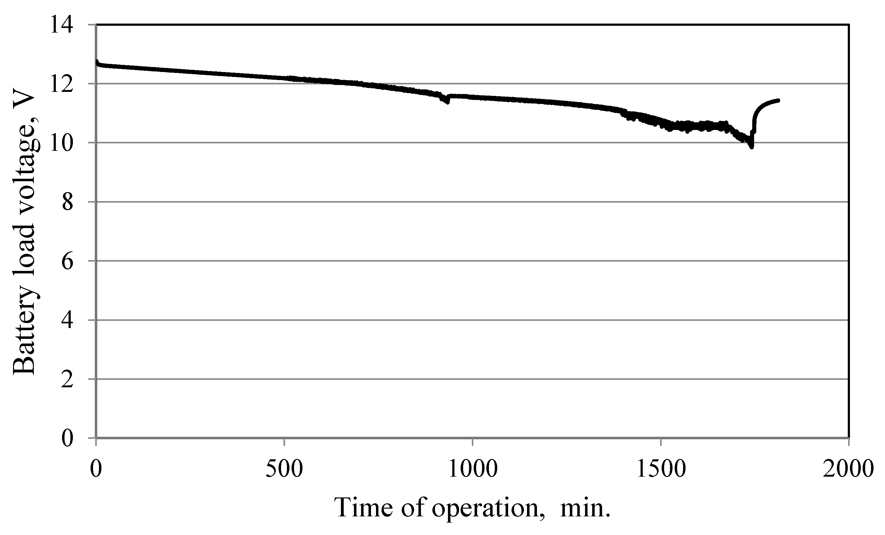
Figure 13 shows the time variation of the load voltage of the battery during the experiment. The load voltage reaches 10 V (minimum value) after 1750 min, then the light is turned off. It can be seen from the figure that the voltage, immediately after the light turns off, jumps to around 11 V. The readings taken after the light turns off represent the open voltage for the battery, which is why it increases. This behavior supports our decision to use load voltage for deciding on energy level inside the battery. Another reason for this sudden increase is partly because of the active chemical reaction inside the battery.
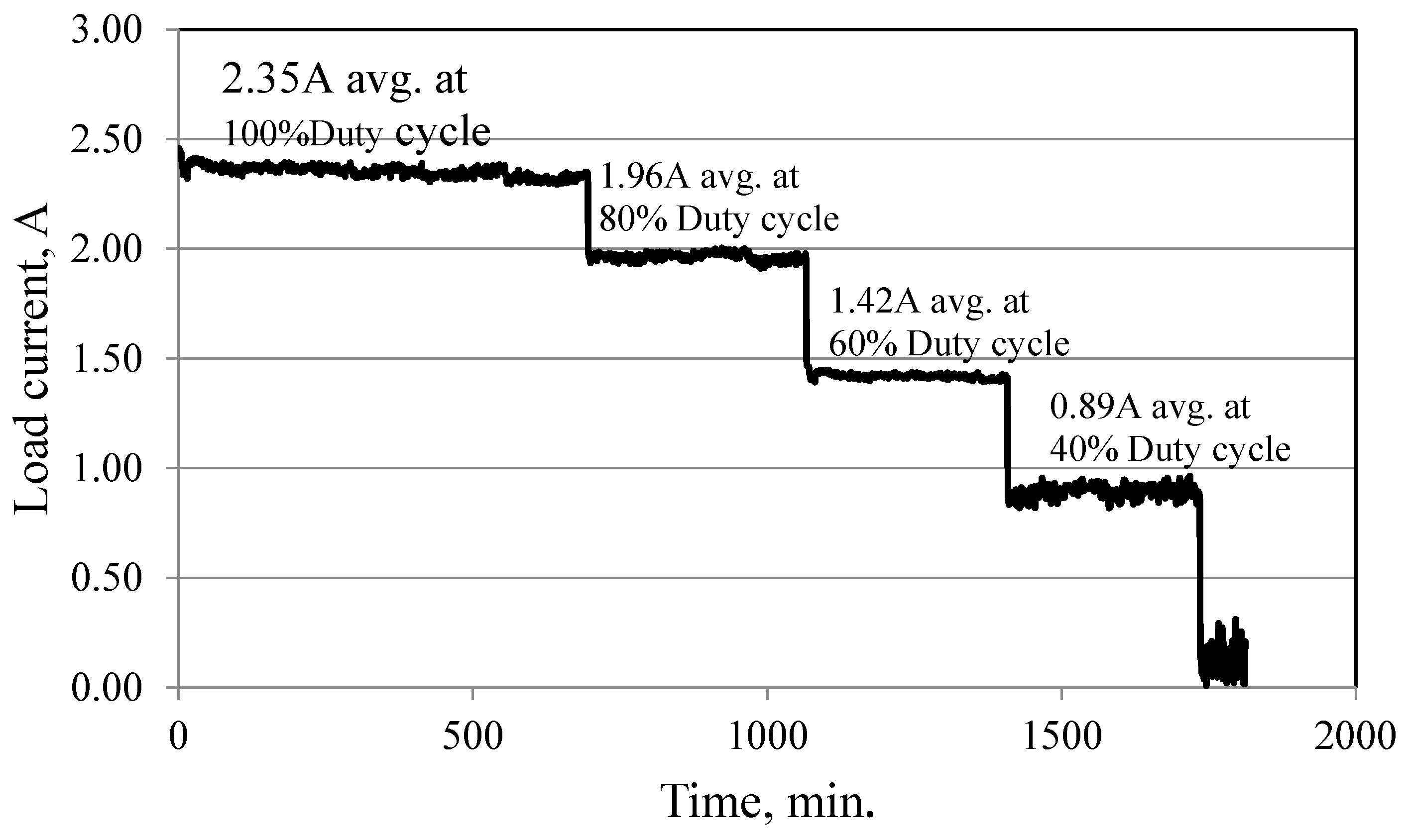
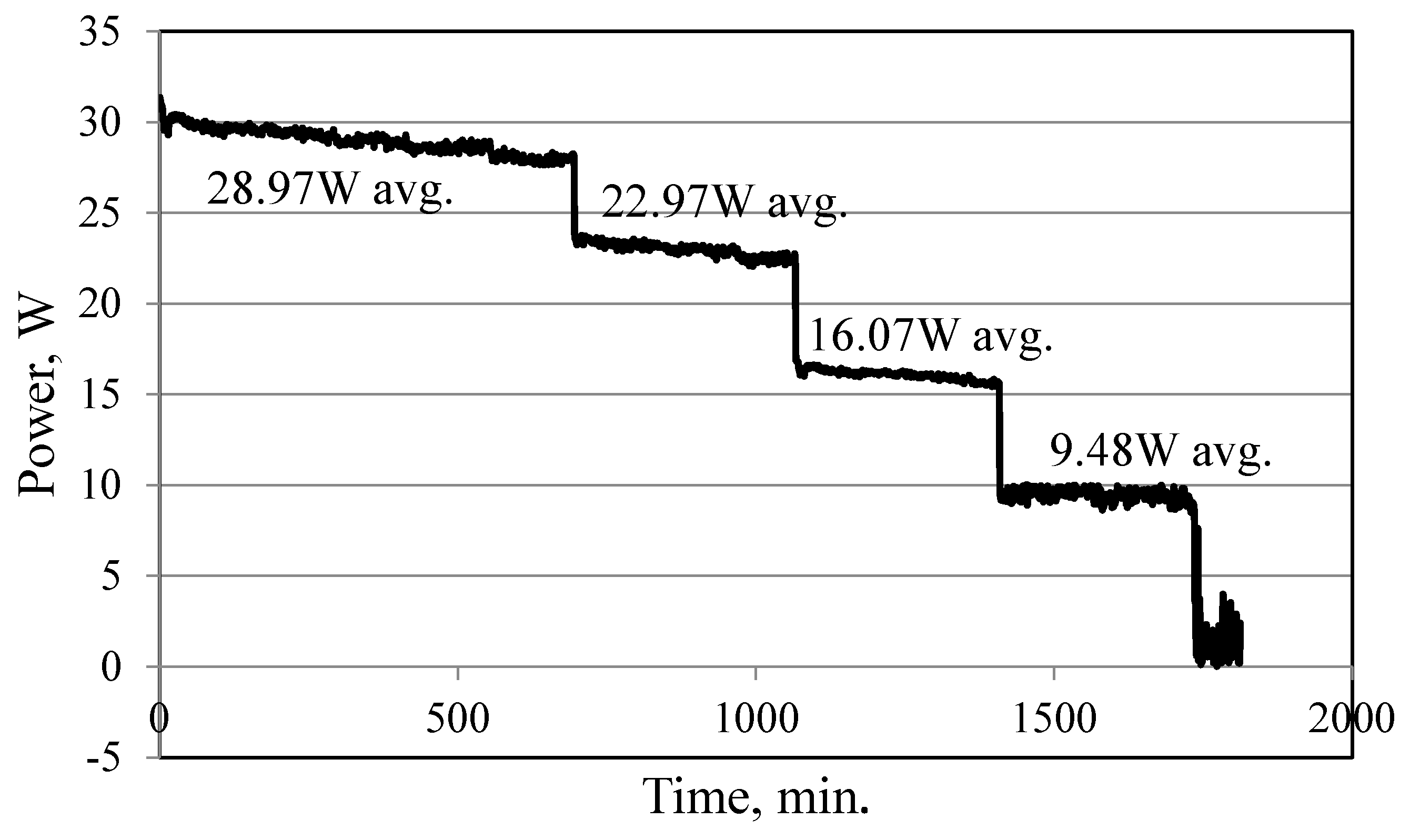
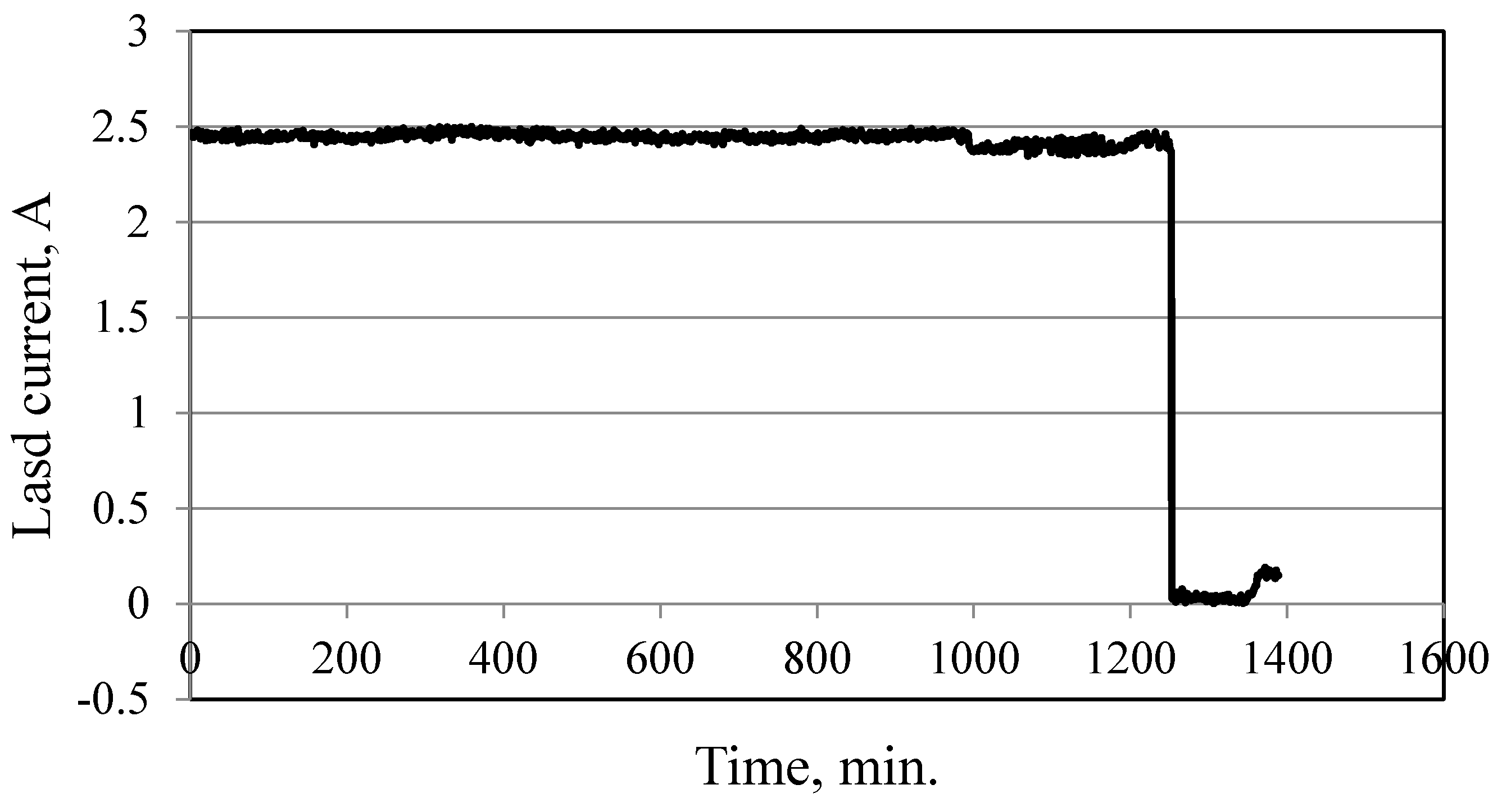
Figure 14 shows the variation of the electric current with time. The electric current varies because the load was varying, due to the dimming process derived from the controller. Figure 15 proves that the amount of energy withdrawn from the battery changes with the load variation driven by the dimmer and activated by the controller in Figure 16. The total energy withdrawn from the fully charged battery is 619 Wh.
5.2. CASE 2: Conventional Controller
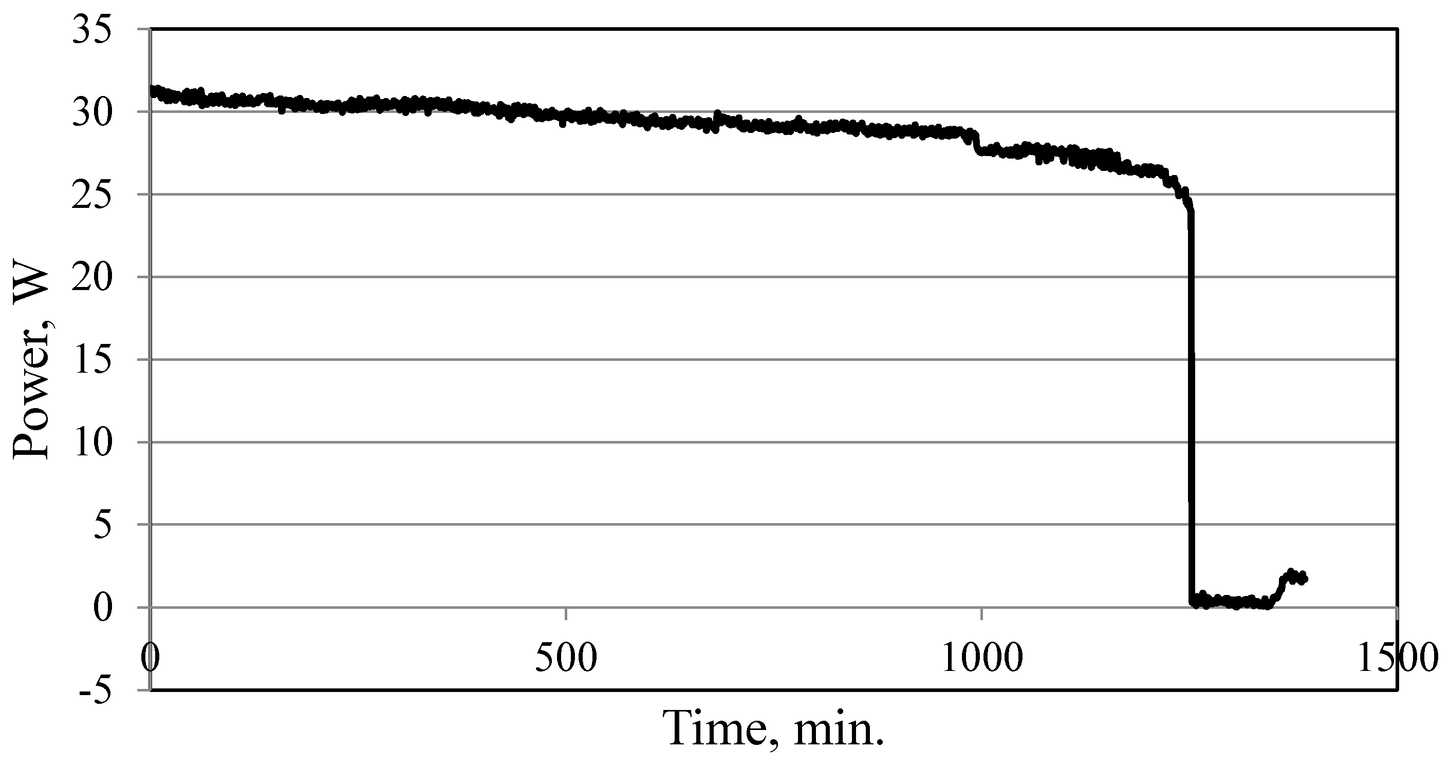
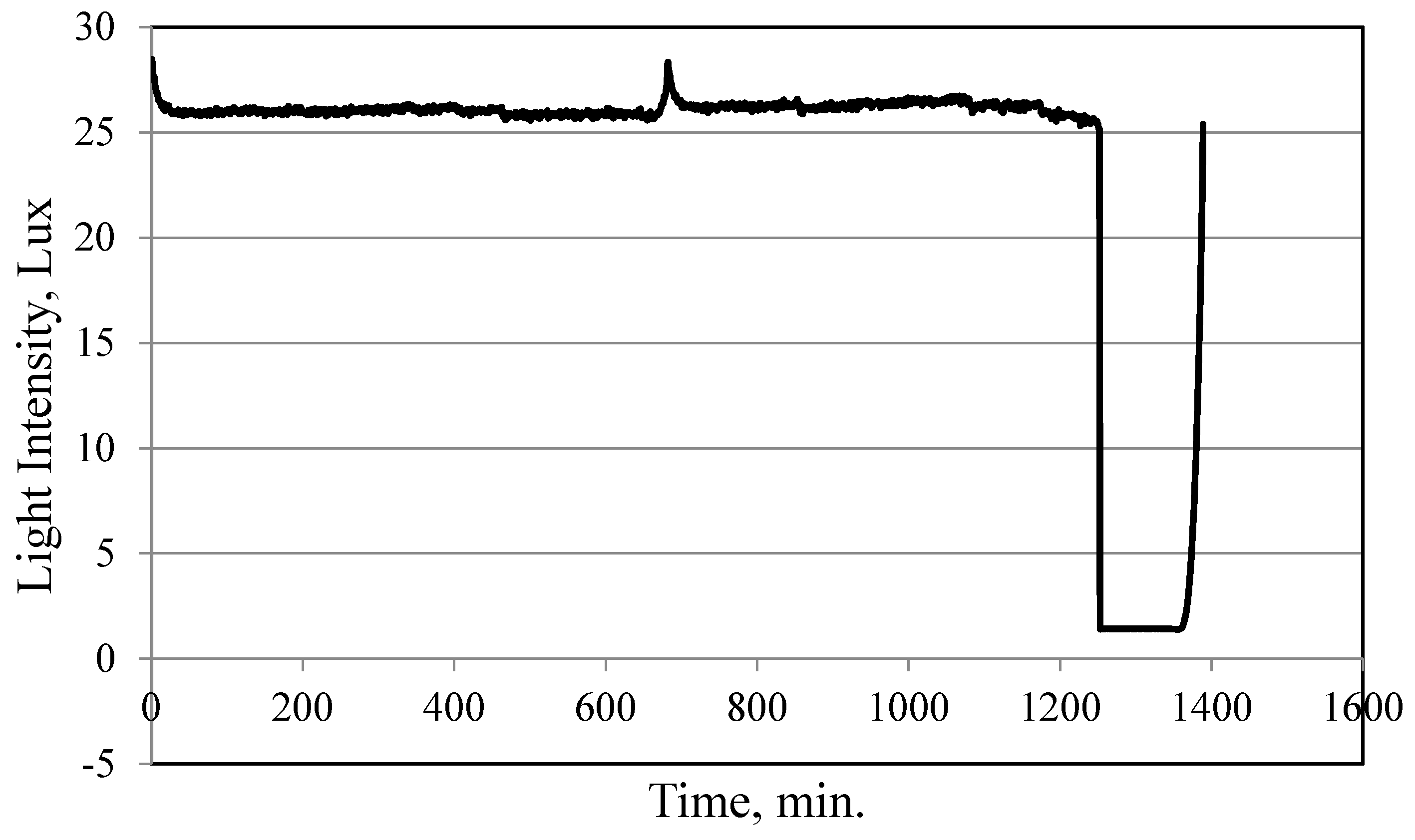
The battery is fully charged and the system operated as in the previous case, continuously, until the battery is fully discharged. Figure 17, Figure 18, Figure 19 and Figure 20 show that the light suddenly turns off after 1250 min of operation. The voltage and energy consumption decrease linearly for the first 1000 min, and then start to decrease sharply. The energy delivered by the battery to the load during this test was 618 Wh, which is almost the same amount delivered during the new controller tests (619 Wh).
6. Conclusions
In this work, a novel simple solar driven LED outdoor lighting system is designed, built, and tested. The lighting system is equipped with a newly designed controller. This controller aims at elongating the time of operation of the standalone lighting system by managing the withdrawal of energy from the system battery and keeping the light “on” as long as possible. The test results showed that the designed controller was operating as designed. The operation hours of the newly designed system are compared with the conventional system. Results showed that the operating hours of the system with the new controller reached 29.16 h (1750 min), while the operating hours for the conventional system were 20.86 h (1252 min).
Finally, it is worth addressing the issue of the cost of the new controller. The cost of all main parts of the controller developed in this work, which include the regulator, scaling voltage circuitry, LDR sensor circuitry, a microcontroller unit, and the LED driving circuit, is about $60. Moreover, it is believed that the cost of manufacturing the new controller will not be much higher than the conventional one. The additional cost of the new controller over the lifetime of such systems can be easily justified, especially when the security and the lifetime improvements of the battery achieved, by avoiding the overdischarge in conventional systems, are considered.
Author Contributions
All the authors collaborated in the study and the paper elaboration. In particular, S.K. designed the study, established the parameters to be assessed and followed-up the data analysis and finalized the paper writing. He is also the corresponding author. A.A.M. is a master student who carried out the literature review, prepared the experimental setup and carried out the experimentations. Furthermore, A.A.M. analyzed the data and drafted the paper. A.A.-G. followed the building and testing of the controller.
Acknowledgments
The authors would like to express their gratitude to the Deanship of Research—Jordan University of Science and Technology—for funding this research under grant no. 144 in 2012.
Conflicts of Interest
The authors declare no conflicts of interest. The sponsor had no role in the design of the study; in the collection, analyses, or interpretation of data and the writing of the manuscript.
References
- Foster, R.; Ghassemi, M.; Cota, A. Solar Energy—Renewable Energy and the Environment, 1st ed.; Taylor and Francis Group, LLC.: Boca Raton, FL, USA, 2010. [Google Scholar]
- Alata, M.; Al-Nimr, M.; Qaroush, Y. Developing a multipurpose sun tracking system using fuzzy control. Energy Convers. Manag. 2005, 46, 1229–1245. [Google Scholar] [CrossRef]
- Fathi, M.; Chikouche, A. LEDs application to the photovoltaic street lighting. In Proceedings of the International Conference on Renewable Energy (ICRE), Damascus, Syria, 5–8 April 2010. [Google Scholar]
- Wu, M.S.; Huang, H.H.; Huang, B.J.; Tang, C.W.; Cheng, C.W. Economic feasibility of solar-powered led roadway lighting. Renew. Energy 2009, 34, 1934–1938. [Google Scholar] [CrossRef]
- Sperber, A.N.; Elmore, A.C.; Mariesa, L.; Jeffrey, D.C. Performance evaluation of energy efficient lighting associated with renewable energy applications. Renew. Energy 2012, 44, 423–430. [Google Scholar] [CrossRef]
- Costa, M.; Costa, G.H.; Anderson, S.; Schuch, L.; José, R. High Efficiency Autonomous Street Lighting System Based on Solar Energy and Leds; Institute of Electrical & Electronics Engineers: Piscataway Township, NJ, USA, 2009. [Google Scholar]
- Huang, B.J.; Wu, M.S.; Hsu, P.C.; Chen, J.W.; Chen, K.Y. Development of high-performance solar LED lighting system. Energy Convers. Manag. 2010, 51, 1669–1675. [Google Scholar] [CrossRef]
- Fathi, M.; Chikouche, A.; Abderrazak, M. Design and realization of LED Driver for solar street lighting Applications. Energy Procedia 2011, 6, 160–165. [Google Scholar] [CrossRef]
- Liu, H.; Wang, Y.; Zhang, X.; Xu, D.; Guo, L. Dimmable Electronic Ballast for 250W HPS Lamp in Street Lighting with Analog Dimming Interface Circuit. In Proceedings of the APEC 07—Twenty-Second Annual IEEE Applied Power Electronics Conference and Exposition, Anaheim, CA, USA, 25 February–1 March 2007. [Google Scholar] [CrossRef]
- Kim, D.; Park, S. Improving community street lighting using CPTED: A case study of three communities in Korea. Sustain. Cities Soc. 2017, 28, 233–241. [Google Scholar] [CrossRef]
- Yoomak, S.; Ngaopitakkku, A. Optimisation of lighting quality and energy efficiency of LED luminaires in roadway lighting systems on different road surfaces. Smart Cities Soc. 2018, 38, 333–347. [Google Scholar] [CrossRef]
- Campisi, D.; Gitto, S.; Morea, D. Economic feasibility of energy efficiency improvements in street lighting systems in Rome. J. Clean. Prod. 2018, 175, 190–198. [Google Scholar] [CrossRef]
- Campisi, D.; Gitto, S.; Morea, D. Light Emitting Diodes technology in public light system of the Municipality of Rome: An economic and financial analysis. Int. J. Energy Econ. Policy 2017, 7, 200–208. [Google Scholar]
- Cucchiella, F.; D’Adamo, I.; Gastaldi, M. Photovoltaic energy systems with battery storage for residential areas: An economic analysis. J. Clean. Prod. 2018, 131, 460–474. [Google Scholar] [CrossRef]
- Park, S.; Kang, B.; Choi, M.; Jeon, S.; Park, S. A micro-distributed ESS-based smart LED streetlight system for intelligent demand management of the micro grid. Sustain. Cities Soc. 2018, 39, 801–813. [Google Scholar] [CrossRef]
- Elejoste, P.; Angulo, I.; Perallos, A.; Chertudi, A.; Zuazola, I.J.G.; Moreno, A.; Azpilicueta, L.; Astrain, J.J.; Falcone, F.; Villadangos, J. An easy to deploy street light control system based on wireless communication and LED technology. Sensors 2013, 13, 6492–6523. [Google Scholar] [CrossRef] [PubMed]
- Light Dependent Resistors. Available online: http://www.technologystudent.com/elec1/ldr1.htm (accessed on 10 April 2018).
- What Is LDR? Basics of Light Dependent Resistor. 2011. Available online: http://vsagar.com/2011/12/ldr-basics-light-dependent-resistor/ (accessed on 20 October 2017).
- Sandhu, H. Making PIC Microcontroller Instruments and Controllers, 1st ed.; McGraw-Hill, Inc.: New York, NY, USA, 2009. [Google Scholar]
- Hellebuyck. Programming PIC Microcontrollers with PicBasic, 1st ed.; Elsevier Science: New York, NY, USA, 2003. [Google Scholar]
- Wilmshurst, T. Designing Embedded Systems with PIC Microcontrollers Principles and Applications, 2nd ed.; Elsevier Ltd.: Oxford, UK, 2007. [Google Scholar]
- Basic Electronics Tutorials Blog, Optocoupler, 29 April 2011. Available online: http://www.electronics-tutorials.ws/blog/optocoupler.html (accessed on 20 October 2017).
- Chadderton, N. Power MOSFET Gate Driver Circuits using High Current Super-B Transistors. In Application Note 18; Zetex: Oldham, UK, 1996. [Google Scholar]
- eCircuitCenter, Push-Pull Output Stage. Available online: http://www.ecircuitcenter.com/Circuits.htm (accessed on 20 October 2017).
Figure 1.
Typical photovoltaic (PV) outdoor light system components.

Figure 2.
The general picture of the prototype.

Figure 3.
Block diagram of the proposed smart discharge control system.

Figure 4.
Complete schematic diagram of a discharge controller.

Figure 5.
Schematic diagram of the 5 V regulated voltage.

Figure 6.
Schematic diagram of a voltage scaling circuit.

Figure 7.
Schematic diagram of the LDR sensor.

Figure 8.
Microcontroller unit circuit with input/output.

Figure 9.
Schematic diagram of LED driving circuit by PWM.

Figure 10.
Flowchart of the discharge controller algorithm.

Figure 11.
Battery discharge curve regions.

Figure 12.
Schematic diagram of the experimental setup.

Figure 13.
Variation of battery voltage during system operation with the smart controller.

Figure 14.
Variation of load (discharge) current during system operation with the smart controller.

Figure 15.
Power of the load during system operation with the smart controller.

Figure 16.
Variation of light intensity at the floor directly under the LED and 6 m away with using the smart controller.
Figure 16.
Variation of light intensity at the floor directly under the LED and 6 m away with using the smart controller.

Figure 17.
Battery discharge voltage behavior without the smart controller.

Figure 18.
Load current without the smart controller.

Figure 19.
Power consumed without the smart controller.

Figure 20.
Variation of light intensity at the floor directly under the LED and 6 m away without using the smart controller.
Figure 20.
Variation of light intensity at the floor directly under the LED and 6 m away without using the smart controller.


Table 1.
Sizing summary of prototype system components.
| Application | Stand-Alone Outdoor Lighting System | |
|---|---|---|
| Location | JUST | |
| Latitude | 32.5 N | |
| Longitude | 35.7 W | |
| Loads | ||
| A1 | Battery Voltage | 12 volts |
| A2 | Rated Wattage (LED Fixture) | 30 W |
| A3 | Hours Per Day Used | 10 h |
| A4 | Energy Per Day (A2 × A3) | 300 Wh |
| A5 | Total energy demand per day (A4) | 300 Wh |
| A6 | Total amp-hour demand per day (A5/A1) | 25 Ah |
| A7 | Peak dc power requirement (A2) | 30 W |
| Battery sizing | ||
| B1 | Days of storage required (autonomy) | 3 days |
| B2 | Allowable depth-of-discharge limit | 0.75 |
| B3 | Required battery capacity (A6 × B1/B2) | 100 Ah add 20% losses = 120 Ah |
| B4 | Amp-hour selected battery (Philadelphia solar company) | 100 Ah |
| B5 | Number of batteries in parallel (B3/B4) | 1 battery |
| B6 | Number of batteries in series (A1/battery voltage) | 1 battery |
| B7 | Total number of batteries (B5 × B6) | 1 battery |
| B8 | Total battery amp-hour capacity (B5 × B4) | 100 Ah |
| B9 | Total battery kilowatt-hour capacity (B8 × A1/1000) | 1.200 kWh |
| PV array sizing | ||
| C1 | Total energy demand per day (A4) | 300 Wh |
| C2 | Battery round trip efficiency (0.70–0.85) | 0.8 |
| C3 | Required array output per day (C1/C2) | 375 Wh |
| C4 | Selected PV module max power voltage at STC (x.85) | 15.1 V |
| C5 | Selected PV module guaranteed power output at STC | 90 Wp |
| C6 | Peek sum hours at design tilt for design month | 5 h |
| C7 | Energy output per module per day (C5 × C6) | 450 Wh |
| C8 | Module energy output at operating temperature (DF × C7) DF = 0.80 for hot climates and critical applications. DF = 0.90 for moderate climates and non-critical applications | 405 Wh |
| C9 | Number of modules required to meet energy requirements (C3/C8) | 1 module |
| C10 | Number of modules required per string (A1/C4) rounded to the next higher integer | 1 module |
| C11 | Number of strings in parallel (C9/C10) rounded to the next higher integer | 1 string |
| C12 | Number of modules to be purchased (C10 × C11) | 1 module |
| C13 | Nominal rated PV module output | 90 Wp |
| C14 | Nominal rated array output (C13 × C12) | 90 W |
© 2018 by the authors. Licensee MDPI, Basel, Switzerland. This article is an open access article distributed under the terms and conditions of the Creative Commons Attribution (CC BY) license (http://creativecommons.org/licenses/by/4.0/).
Share and Cite
MDPI and ACS Style
Kiwan, S.; Abo Mosali, A.; Al-Ghasem, A. Smart Solar-Powered LED Outdoor Lighting System Based on the Energy Storage Level in Batteries. Buildings 2018, 8, 119. https://doi.org/10.3390/buildings8090119
AMA Style
Kiwan S, Abo Mosali A, Al-Ghasem A. Smart Solar-Powered LED Outdoor Lighting System Based on the Energy Storage Level in Batteries. Buildings. 2018; 8(9):119. https://doi.org/10.3390/buildings8090119
Chicago/Turabian StyleKiwan, Suhil, Anwar Abo Mosali, and Adnan Al-Ghasem. 2018. "Smart Solar-Powered LED Outdoor Lighting System Based on the Energy Storage Level in Batteries" Buildings 8, no. 9: 119. https://doi.org/10.3390/buildings8090119
Note that from the first issue of 2016, this journal uses article numbers instead of page numbers. See further details here.