Article

Manufacturing, Modeling, Implementation and Evaluation of a Weatherproof Seal for Prefabricated Construction

Center for Advance Manufacturing of Prefabricated Housing, The University of Melbourne, Melbourne 3010, Australia
*
Author to whom correspondence should be addressed.
Buildings 2018, 8(9), 120; https://doi.org/10.3390/buildings8090120
Submission received: 30 July 2018 / Revised: 24 August 2018 / Accepted: 28 August 2018 / Published: 31 August 2018
(This article belongs to the Special Issue Modern Prefabricated Buildings)

Abstract

:
Prefabricated forms of construction have led to the rapid onsite assembly of buildings however there are still on-site tasks and processes which can be reevaluated and redone specifically in keeping with the principles of prefabrication instead being adapted to fit its purpose. One such process is that of waterproofing between prefabricated panels and modules which come from the factory fully complete façade and all. Conventional means of waterproofing can be used however it results in more work done on site, potential delays and generally requires access from the external face of the building. This paper presents the Modelling, Implementation and Evaluation of purpose developed weatherproof seals specific for Prefabricated Construction. An overview is provided of the entire development process and specific focus is given to the modeling using finite element analysis (FEA) computer simulations, manufacturing and testing which then resulted in the implementation in a prefabricated panelised building which is used as a case study and the means of further evaluation. These strategies have enabled an efficient and robust prefabricated waterproofing solution specific for this form of construction to be understood and implemented. The resulting case study has successfully verified the time and cost savings when compared to conventional techniques whilst still providing a durable and effective weatherproof seal for prefabricated panelised and modular systems.

1. Introduction

This research study presents a prefabricated focused solution which is entirely completed offsite which surpass current convention means of onsite weatherproofing of gaps which entails setting up scaffolding to reach work height, manually pushing in a flexible foam backing rod and then manually applying a caulking/sealant generally silicone then manually tooling to achieve the correct profile are adopted for prefabricated panelised and modular constructions in filling the gaps between each wall or module [1]. This labour intensive primitive means of weatherproofing does not align directly with the values of efficiency in prefabrication. Quicker means of weatherproofing specifically designed for prefabricated panelised and modular type of construction and assembly is in order and are presented, modelled, manufactured, implemented on a case study, monitored and evaluated.
Prefabrication and onsite assembly of prefabricated components presents itself a unique set of requirements and challenges which the current conventional means of sealant joints doesn’t tackle well non-the least that it require considerable on site labour and access from external face of the building. Prefabrication in the modern construction industry generally comes closed/complete such as in some panelised or modular systems or open/incomplete such as pods and stick and frame assembly, however there are also open panelised systems or un-cladded and hence incomplete modular systems, to fully prefabricate a building it must be complete be it in pieces which require assembling but complete nonetheless [2]. The most complete systems for walls would be those which include internal finish to external façade and likewise for floors those which includes from ceiling to flooring and everything in-between or at least with built in provision for electrical, water, gas and heating, ventilation, air conditioning (HVAC) systems [3].
There are many intrinsic challenges to fully prefabricate a building such as flexibility of design and method of connections, currently parts of industry have adapted to prefabrication by picking and choosing which processes are most valuable to them to incorporate in prefabrication [4]. These have generally been either major labour and skill intensive processes such as sawing and cutting which can be replaced with CNC or simple tasks which are easy to automate such as nailing or gluing [5], thus this leads to extending these principles to the sealing solution between panels or modules and incorporating the same principles into developing a new solution which can be installed offsite and not onsite. The offsite installation can be integrated to the manufacturing processes of the complete forms of this prefabrication method and may also be automated. This potential sealing solution for prefabricated construction will be modeled, implemented evaluated.

2. Conventional Solution

Current practice which is considerably widespread for the filing and sealing of joints is grouting and another is the backer rod and caulking/sealant solution. Grouting involves using a cementitious material to fully seal and join the gap between two other cementitious materials [6]. This wet trade is much easier done on horizontal joins such as those in bridge decks [7] where the gaps are manually filled onsite with a viscous cementitious grout. In this process pre-moistening the surface is recommended to enhance the performance of the bond [8]. The limiting factors of grouting is that it is constrained to joining between cementitious surfaces, better suited for horizontal and not vertical gaps and joins and requires onsite manual labor all of which do not lend to an efficient and versatile prefabrication sealing solution for vertical joins in prefabricated walls and or modules. As for the backer rod and caulking/sealant solution the procedure begins with a worker who is at the working height for the entire height of a wall which makes it considerably unpractical and dangerous for taller buildings. The worker must clean both surfaces properly then manually push in a flexible foam backing rod to a specified distance along the entire length of the wall and then manually apply a caulking/sealant (generally silicone) along this length then manually tool it to achieve the correct hourglass profile.
Since there are so many labour intensive steps workers often take shortcuts to which have consequences later in the buildings life. For example pushing the backing rod too far in may result in adhesion failure as the layer of caulking/sealing must not be too thick as not to be able to accommodate for the tolerances required when the building/panels move be it due to thermal expansion or for dynamic reasons [9]. The adhesion fails and separation occurs as the caulking/sealant is not in the narrow hourglass figure and hence the increase pulling force acting against the adhesion.
If the rod is too close to the surface there may not be enough cohesive force in the caulking/sealant for such a narrow section. Additionally if the walls are not cleaned properly and free from dust prior to installation of the backer rod and caulking/sealant then separation will occur. Lastly if the width of the gap varies that is the tolerances are not all the same then an appropriately sized backing rod and appropriately profiled section must be done otherwise splitting will occur. Using sealant as the primary means of weatherproofing without further protection such as a drained joint is fundamentally not a rigorous solution especially considering that the joint can only be inspected from the outside. The time where the use of sealant that can be best relied upon in this manner is when used between glass to glass joint’s where both sides can be easily inspected and the design requires openness [10].
Poor workmanship along with sealant distress are amongst the leading reasons for why a building will leak [10]. Therefore there is a need to develop new seals which do not rely as heavily on workmanship and are able to be completed offsite are required for prefabricated forms of construction.

3. Proposed Solution

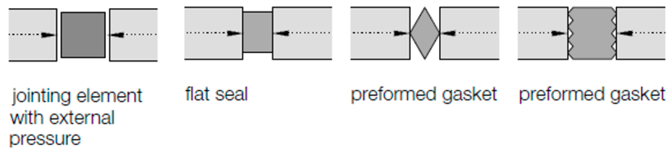
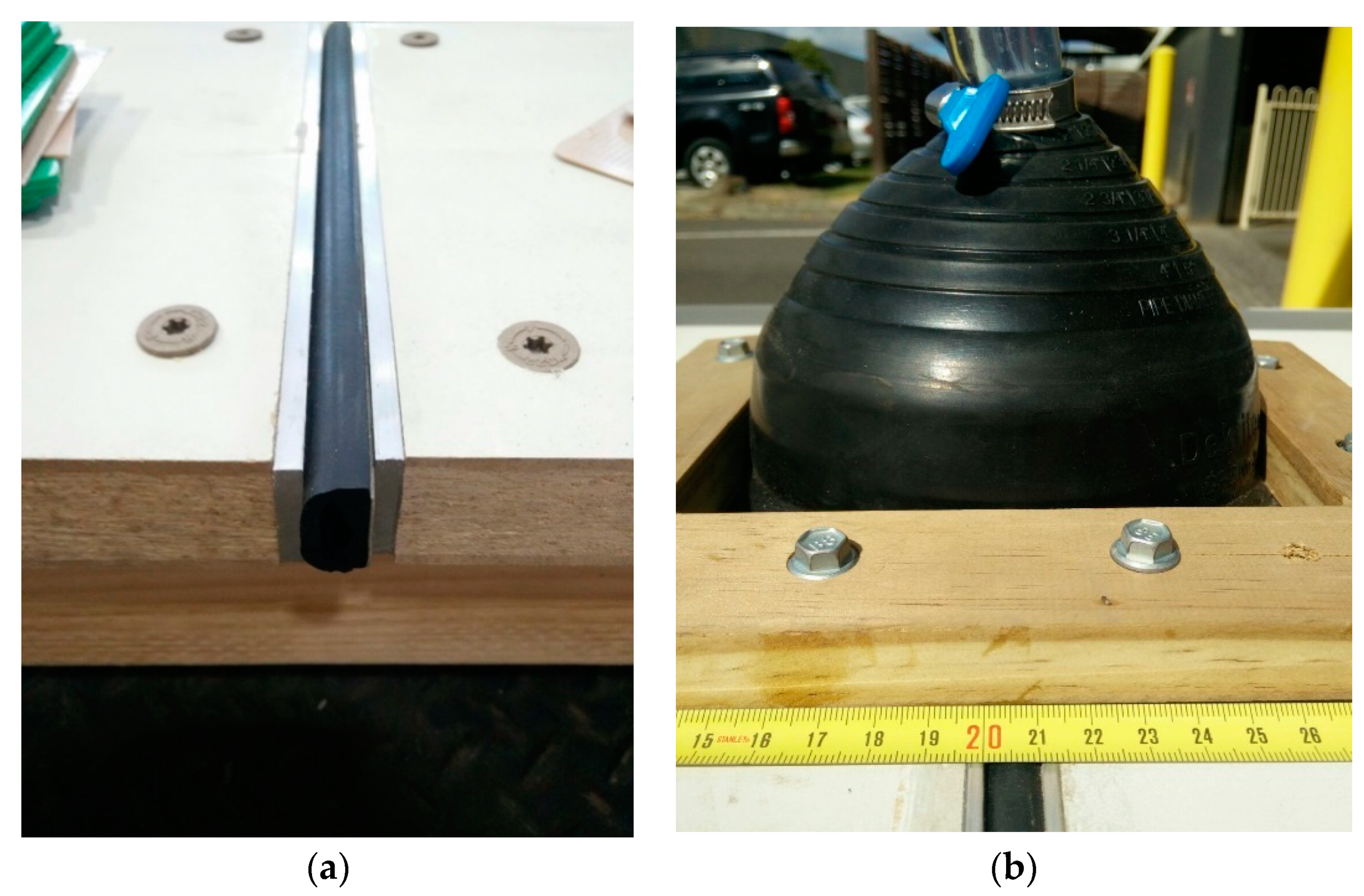
A rubber gasket sealing solution which would be installed off-site in the factory on the outside edge of prefabricated panels or modules and would inherently compress to a required level due to the placement of the panels or modules has been devised to meet the most optimal criteria of not requiring any onsite installation and does not need any work to be carried outside of the building envelope.
The gasket seals or ‘jointing element’ which will compress under in plane loading as the resultant pressure to act as a physical barrier to water penetration as shown in Figure 1 below.
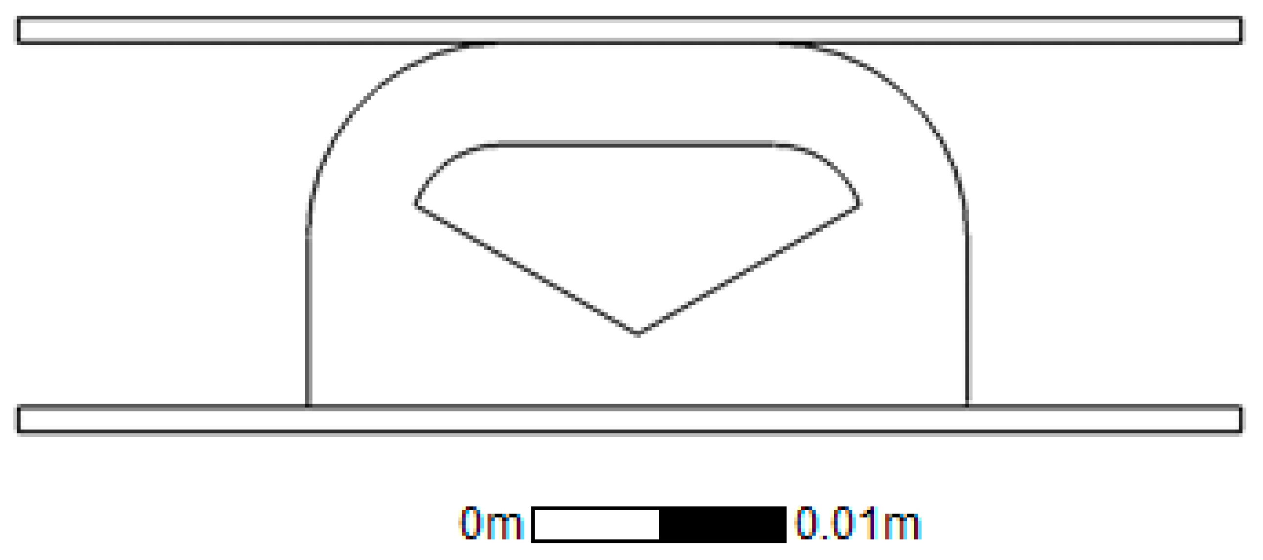
The suitability of this type of sealing solution specifically for sealing in between panels in prefabricated panelised construction was firstly due to the fact that the required compressive force can be naturally applied through the placement of the wall panels during the lifting and cranage stage onto the appropriate supporting connections. The level of force required compression may be an initial concern however with a correctly design cross section in which the gasket can fold into a void this is able to be worked around, additionally the mass of a completed panels and modules itself then the seal would be able to absorb the range of in plane tolerances which is typically experienced. Thirdly and finally the gasket solution was envisioned to be able to be pre-installed onto the wall panel making for an extremely efficient on site installation to which is of great importance to this form of construction and is also the primary identified objective and differentiating factor with the conventional solution. The profile shape of the rubber gasket is visualized below in Figure 2.
The gasket solution developed compromises of a purposefully designed rubber extrusion profile whole one side is flat allowing for a dual face adhesive tape to be applied during the manufacture of the extrusion and an aluminium extrusion which houses the facade panel and frames the end of the timber panelised element. The opposite face is curved to allow for out of plane movements and to help the gasket not to get caught and ripped during handling or installation, with in between a carefully designed void. The void is such that that the centre has more material cut out allowing for dual high pressure zone on the exterior and interior face respectively once compressed. Apart from providing a double barrier effect this also increases the stability of the seal when placed under shear loads which are highly expected when the panel is lowered into place from the adjacent panel.
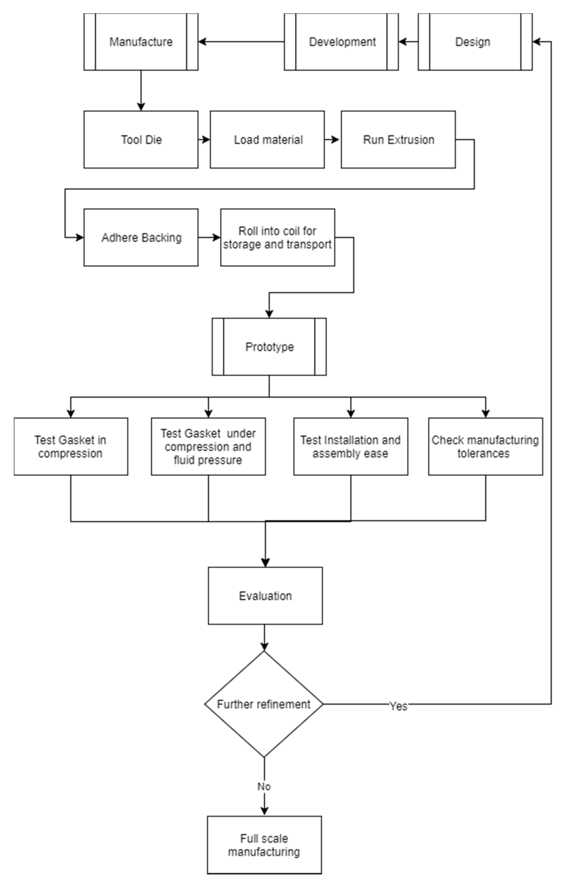
The extruded rubber is made from ethylene propylene diene monomer (EPDM) and has the double sided tape applied to the flat face and then coiled up into long lengths before delivery to the prefabrication factory. EPDM is used in many sealing applications such as in car doors, boot and hood seals it is also an efficient insulator and also does not pollute the water which runs off it and the stiffness can easily be changed during the manufacturing process so that tailored compression can be achieved without having to retool the die for extrusions [12,13,14,15,16].
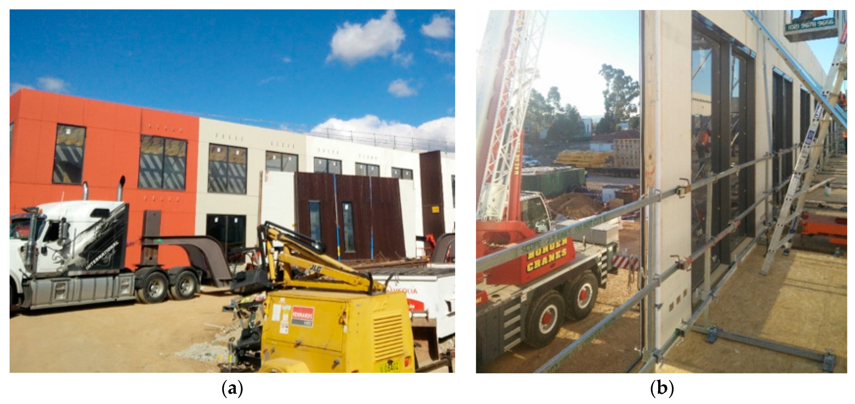
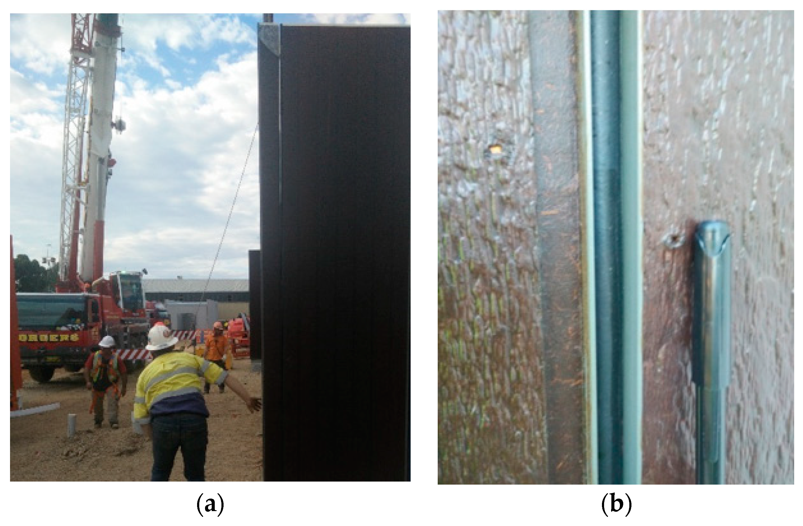
Once delivered at the panel/module prefabrication factory the seal can be affixed to the end of the panel by simply peeling off the backing tape and sticking the seal to the clean outer flat face of the aluminium extrusion and then applied all the way up or down and then cutting to length, alternatively the seal can be cut to length prior to adhesion onto the aluminium extrusion which may make handling easier however it introduces an extra step of measurement. This solution can be used to seal vertical joints between prefabricated panels and modules intended for use in both multilevel commercial and residential developments although with the acceptance of the subjective aesthetic impact of having an exposed design joint.
If handling and transport damage is a concern, particularly with tying panels together for either of these tasks then the seal can simply be applied on site when the truck arrives however the aluminium surface will need to be checked for damage and cleaned before affixing the seal. Another matter to recognise is the introduction of another task on site which may or not be on the critical path dependent on the logistics and delivery although the risk of unwarranted damage of the seal is mitigated.
In the proposal of a new waterproof seal much can be learnt from the challenges encountered in creating past solutions and focus can be directed to these areas.
Experts with considerable experience in façades note that there are a number of weak areas and conditions which should be kept in mind [11]. Some of the most prominent points of interests to consider have found to be as follows: the joints between the walls and floor, deformation of the building because of applied and dead loads, manufacturing, production and assembly related tolerances, dynamic, horizontal floor displacements caused by wind pressure/suction or seismic actions, changes of length due to differing materials and temperatures and finally water penetration through wind driven rain causing pressure on the surface where surface tension and capillary effected water seeps through narrow joints [17]. These areas will be particularly considered in the modeling and implementation of the new sealing solution.
The full possible design criteria for waterproof and weatherproof seals and their influencing factors are needed to be considered and key relevant criteria to be checked against when modeling, implementing and evaluating a new sealing solution specific for use in panelized and modular forms of construction.
External conditions: UV radiation—leading to potential change in colour over time and potential change of stiffness over time, Temperature and temperature change—not to degrade under heat and not to change shape under heat, Humidity and humidity change, Rainfall, Wind pressure, Combined action of wind and rain (wind driven rain), Potential dust, dirt and grime, Chemical resistance—Air pollution and cleaning products.
Internal conditions: Suction pressure, Temperature (condensation risk), Air tightness (not permeable to air), Water tightness (not permeable to water), Ability to relieve vapour pressure, Sound transmission—Airborne sound and Structure-borne sounds.
Interaction between External and Internal conditions: Pressure and suction pressure combination, Tolerances—Production, Erection/Assembly, Deflection of components, Bowing, Creep, Tolerance stack up (the sum of tolerances), Allow air to enter/escape (ventilation), Prevent the condensation of water, Capillary water movement, Allow for differential movements—Deflections before, during and after installation, Long term creep, Dynamic movements, Expansion and shrinkage movements, Horizontal and vertical joints and their movements externally with their relation internally and vice-versa, Force transfer—element by element and supporting construction element, Allow drainage of runoff and infiltrated water, Allow/block passage of light and protection against frost damage (non-absorbing material).
Other:Mass customization and versatility, in order to be a viable solution for many projects and not a one off solution, Allow relative movements—Tolerance, wall displacement further apart (gap larger and smaller), Tolerance, wall displacement out of plane (walls not lining up exactly, one slightly forward and one slightly backwards), compensation for tolerances such as manufacturing tolerances, erection tolerances, movement tolerances, Transportation to site—Damage resistance to abrasion, Damage resistance to impacts (rocks), Assembly—handling not to cause damage and ease of installation, Service life of the building—Design life, Maintenance required and ease of maintenance and susceptibility to insect and bird attack.
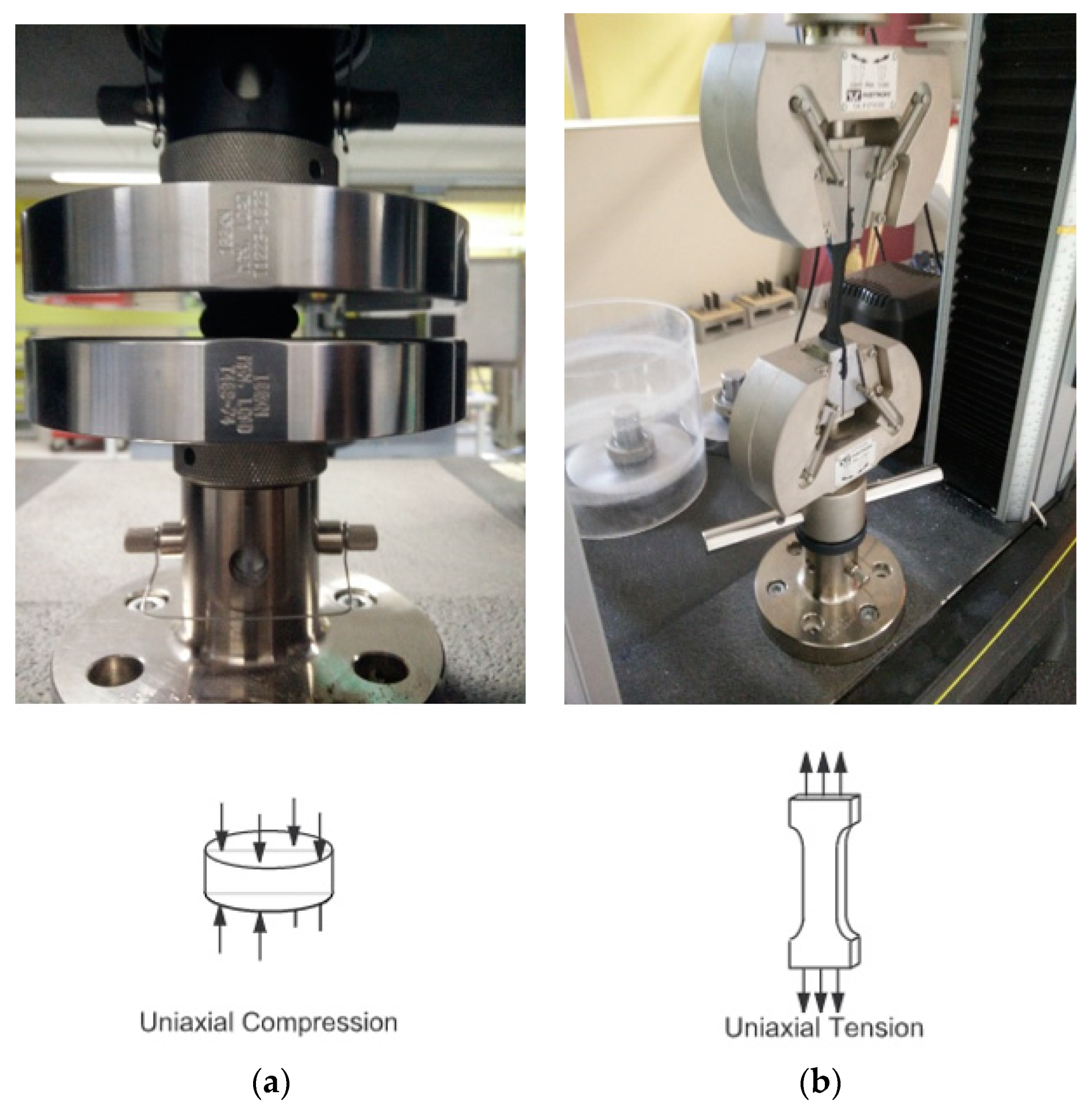
4. Method

Once the design and development of a new solution can be justified the design and development can begin, during this a model (may be physical or digital) of the generated proposed solution is created. Once a proposed solution is created it is then modeled, tested and evaluated, there may be an iterative cycle back to the design stage until the decision is made to proceed manufacturing, form here small scale and large scale testing can be conducted on a representative manufactured prototype, further refinement may be made to the design, once refined further manufacturing can take place, full scale testing which may not of been possible with sample manufacturing may now take place, a successful result leads to full scale manufacturing and adoption to projects to which are monitored and evaluated with learnings continuously incorporated. This method is outlined below in Figure 3.
In implementing a new solution, it is recommended that thought should be placed upon measuring the performance of the outcome, requirements are to be identified and tested or compared against. Defining all the certainties and restraints narrows the scope and helps provide a boundary in which to evaluate solution. One such certainty that can be made to practically all projects is that the new design must meet the relevant codes and standards, for Australia this would be AS4284: Testing of Building Facades, it primarily compromises of the following tests on a representative sample section of a facade: Air infiltration test, Static pressure test and Dynamic pressure test. Air Infiltration test Testing of the façade with both negative and positive pressure of −150 Pa and +150 Pa respectfully, the air leakage rate for all air-conditioned buildings should not exceed 1.6 L/m2·s and 8.0 L/m2·s for all non-air-conditioned building [18].
In the static pressure test a constant pressure of the greater magnitude between 300 Pa and 0.3 Ws (where Ws is the designed wind pressure) will be used with water sprayed to the external face of not less than 0.05 L/m2·s. The first 5 min will be water sprayed with zero applied pressure, then 15 min of water sprayed with the applied pressure then a final 5 min of water sprayed without the applied pressure, during this time observations are to be made from the internal face and any water ingress and damage is to be recorded.
Finally there is also a dynamic pressure test in which is to be performed after successful completion of the static pressure test. In each stage the pressure cycles between designated pressures which are increasing [18].

5. Manufacturing

The manufacturing process (which also involves assembly) is iterative and contains a lot of learning and feedback. As shown in Figure 4 initial manufacturing begins with the tooling of the initial die, it is important that at this stage that too much material is not taken out in the creation of the die for the proposed geometry as if tailoring on decreasing the size of the extrusion a whole new die is needed to be tooled whereas if an increase in size can be easily account for by tooling the existing die and removing more material. An additional consideration that may need to be accounted for is the complexity of the geometry along with the material which is to be used. Given that the material and the material temperature once heated results in a viscosity that is compatible with the complexity in the geometry then the material can be loaded into the hopper for meting and then pushed through the die to run the extrusion, there may be some iteration here however once the parameters are set they can be easily maintained. The extrusion which set as it formed through recirculated water cooling the extrusion is dried and the adhesive backing is adhered. One side of the double tape adhesive is peeled and applied whist the other is kept intact and the extrusion which is now the gasket is made from EPDM rubber it can be rolled into coils for storage and transport. This forms the basis of the initial gasket prototype which will be then subjected to several tests. The first such test was the compression of the gasket whilst checking for deformation profile and for the force required to compress the gasket to the designed level. This is an important test to do as it validates the finite element model and confirms the expected behavior so that there will not be an issue on site when the panels are place such that the gasket will compress appropriately. Next a test for ease of installation which is be the manual unpacking and handling the coil, striping the backing tape and application of the gasket to the edge of the wall closest to the exterior face is done. Now that it has been established that the gasket can be installed on the wall to a controlled level of precision with ease and can be compressed by the expected amount of force then the next test is the compression and checking for water leakage under fluid pressure. This test is vital to the performance of the gasket seal in waterproofing, once again the results are compared to that of the finite element model and to the minimum requirements as outlined in the relevant standard. Finally testing the manufacturing tolerances through accurate measurements and applying them the each of the tests particularly the deformation profile, force based on compression and check for water leakage under compression so as to establish confidence in the robustness of the solution.

6. Modeling

Acquiring the properties of rubber which as common material for gasket type seals is important to understand and additionally significant in the fact that this it will be imported into a numerical model to simulate the seal, thus the accurate capturing of this data is crucial to the accurate modelling of it. The relevant codes have been found to be: ASTM D575 (2018) Standard Test Methods for Rubber Properties in Compression [19], ASTM D395 (2016) Standard Test Methods for Rubber Property—Compression Set [20] and ASTM D412 (2016) Standard Test Methods for Vulcanized Rubber and Thermoplastic Elastomers—Tension [21]. Photographs of the tests carried out are shown in Figure 5a,b below.
The surface of and the method to permanently fix a gasket or other solution to weatherproofing to the structure of the wall panel or module needs to be considered just as much as any other surface to the seal. Generally an attachment such as a seal particularly a gasket can be affixed through method of adhesions thus the relevant codes have been found to be: ASTM-D897 (2016)—Standard Test Method for Tensile Properties of Adhesive Bonds [22], DIN EN-15870 (2009) (also the same as ISO-6922 [23]) Adhesives—Determination of tensile strength of butt joints[24] and ASTM-C907 (2017)—Standard Test Method for Tensile Adhesive Strength of Preformed Tape Sealants by Disk Method [25].
Finally gasket type seals and in seals in general which require friction to operate or may encounter friction during assembly, thus the relevant codes have been found to be: ASTM-D1894 (2014)—Standard Test Method for Static and Kinetic Coefficients of Friction of Plastic Film and Sheeting [26] and ISO-15359 (1999) Horizontal Plane Method [27].

6.1. Hyperelastic Material Model

A constitutive model for an ideal elastic material is known as a Hyperelastic material model which has a stress-strain relationship based from strain deformation energy. Rubber is a typical prime example of suitable material to be modelled in this way as it is defined as non-linear elastic, isotropic and its behaviour is largely independent to strain rate [28]. The identifying characteristics of hyperelastic materials are: significant elongation under and loading, minimal to no permanent deformation of the material after loading, non-linear relationship between force of the load and the stress and finally the internal energy can be used to describe the stress in the material [29]. Hyperelastic material models provide the means to model materials with this behaviour through using a strain energy density function [30].

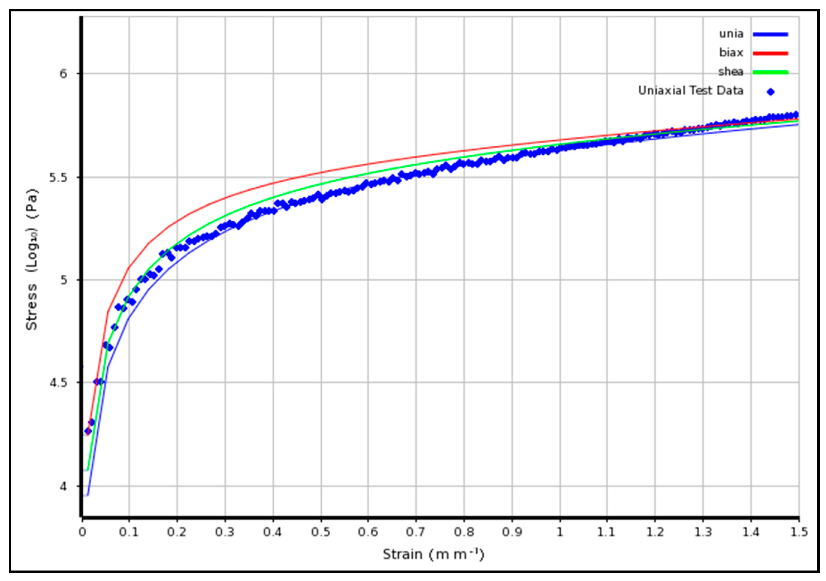
6.2. Neo-Hookean Model

To model the material behaviour of hyperelastic materials it is ideal to have test data from different set of tests, primarily these would be uniaxial, biaxial and shear test. In this study only uniaxial test was carried out for tension and compression of this particular composition of EPDM rubber due to a reasonable understanding on how the material is expected to behave. In circumstances where only uniaxial test data is available a Neo-Hookean model is widely recommended to be used and thus it is the chosen model for this project [31].
The Neo-Hookean model can be useful in prediction of behaviour of elastomers and assumes perfect elasticity through the stages of deformation and can capture non-linear stress-strain relationship. However due to the fact that polymer chains under stress can initially move relative to each other but at a certain stage covalent cross links limit this and hence in turn increased the elastic modulus at this stage, the results is that the Neo-Hookean model is best suited for strains below this level [15].
The Neo-Hookean hyperelastic strain energy function comes in many forms. In ANSYS 17.2 [32] which was used for this project the hyperelastic strain-energy function which was used is as per Equation (1) below.
W = μ 2   ( I 1 3 ) + 1 d   ( J 1 ) 2
where,
μ = initial shear modulus of materials,
d = material incompressibility parameter,
K = initial bulk modulus which is related to the material incompressibility parameter by, K = 2 d .
After preparing the EPDM samples, testing was done on 5 specimens for each test, the average values were used as inputs to the Neo-Hookean material model which ANSYS 17.2 calculated and fitted the curve, the results are as shown in Figure 6. The close fit with the experimental data indicated that the Neo-Hookean will be adequate.

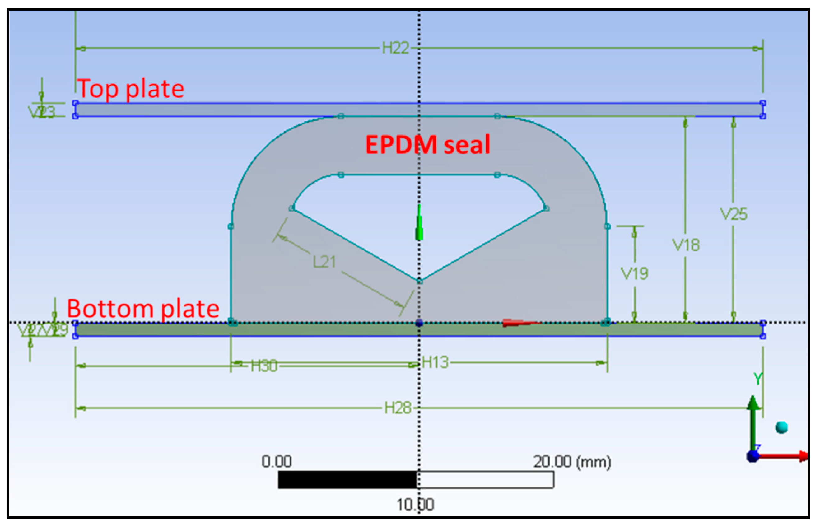
6.3. Finite Element Model

A finite element model (FEM) was developed to evaluate the compression, deformation and interaction with fluid pressure of the rubber gasket solution through ANSYS [32], this is shown in Figure 7.
Simulation comprises two stages. Firstly, stage one, the seal is compressed in the y direction. Secondly stage two, a fluid pressure is applied from the left side of the seal.
The aluminium extrusion is modelled simply as rectangular element as seen at top and bottom plates in Figure 8. The gap is initially 15 mm to match the dimension of the uncompressed seal, it is then reduced to 10 mm. This is done by a gradual displacement of the top plate until it moved 5 mm in the negative y direction. Next an increasing water pressure is applied on the left hand surface until the seal fails due to separation.

6.4. Assumptions/Simulation Setup

The following assumptions and factors was used in the simulation setup:
  • Non-linear static analysis with direct solver.
  • Symmetric, Normal Lagrange contacts.
  • The only mode of failure assumed is the separation between EPDM seal and top plate.
  • Material assumed fully impermeable to fluids.
  • Negligible deformation of top and bottom plates.
  • Plane strain condition initially assumed. This assumption is investigated, the result is a larger material stiffness compared to plane stress as the material is not allowed to deform out of plane.
  • A friction factor of 0.1 between top plate and EPDM rubber. This assumption is investigated through a sensitivity analysis, the result is that overall sealing performance is not primarily sensitive to friction.

6.5. Deformation Analysis and Verification of Stage One

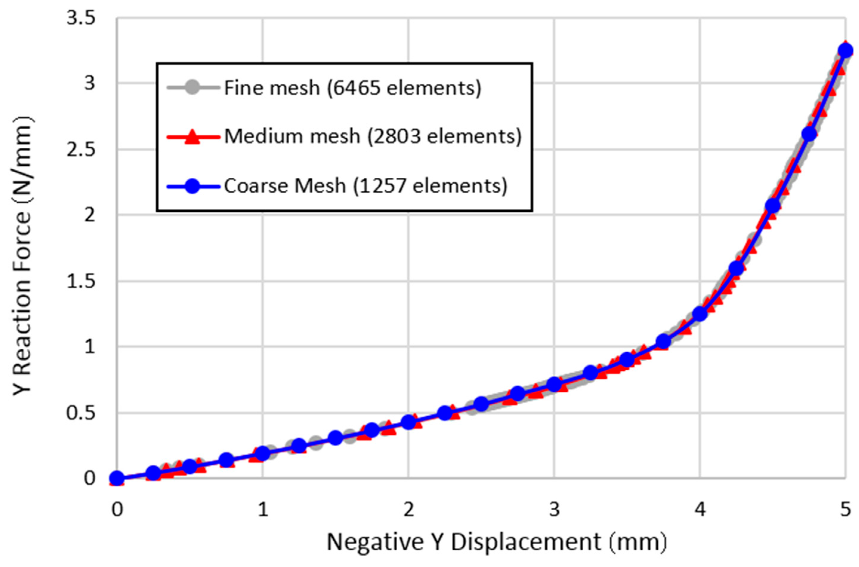
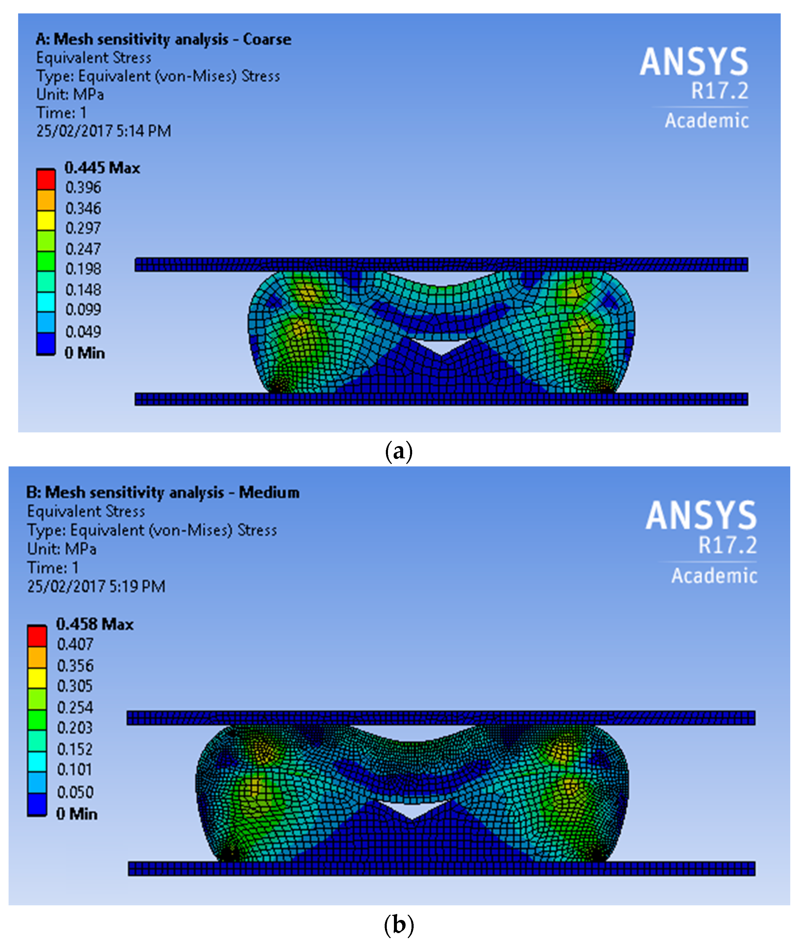
The finite element analysis (FEA) solution is verified for the deflection analysis before fluid pressures are applied in stage two. This includes examining the mesh, the plane strain assumption, and friction properties.
A mesh sensitivity study is performed in order to obtain an optimal mesh configuration that produces accurate results at low computational cost. Three mesh configurations of increasing refinement are generated, and key results (reaction vertical force in Figure 8 and element stresses in Figure 6) are compared for the three mesh configurations as shown in Figure 9a–c.
There is minimal difference in the solution between the mesh configurations. The medium mesh is selected for this project. For fluid pressure penetration cases, the medium mesh is further refined at the location of initial separation to better predict fluid penetration in this key region.

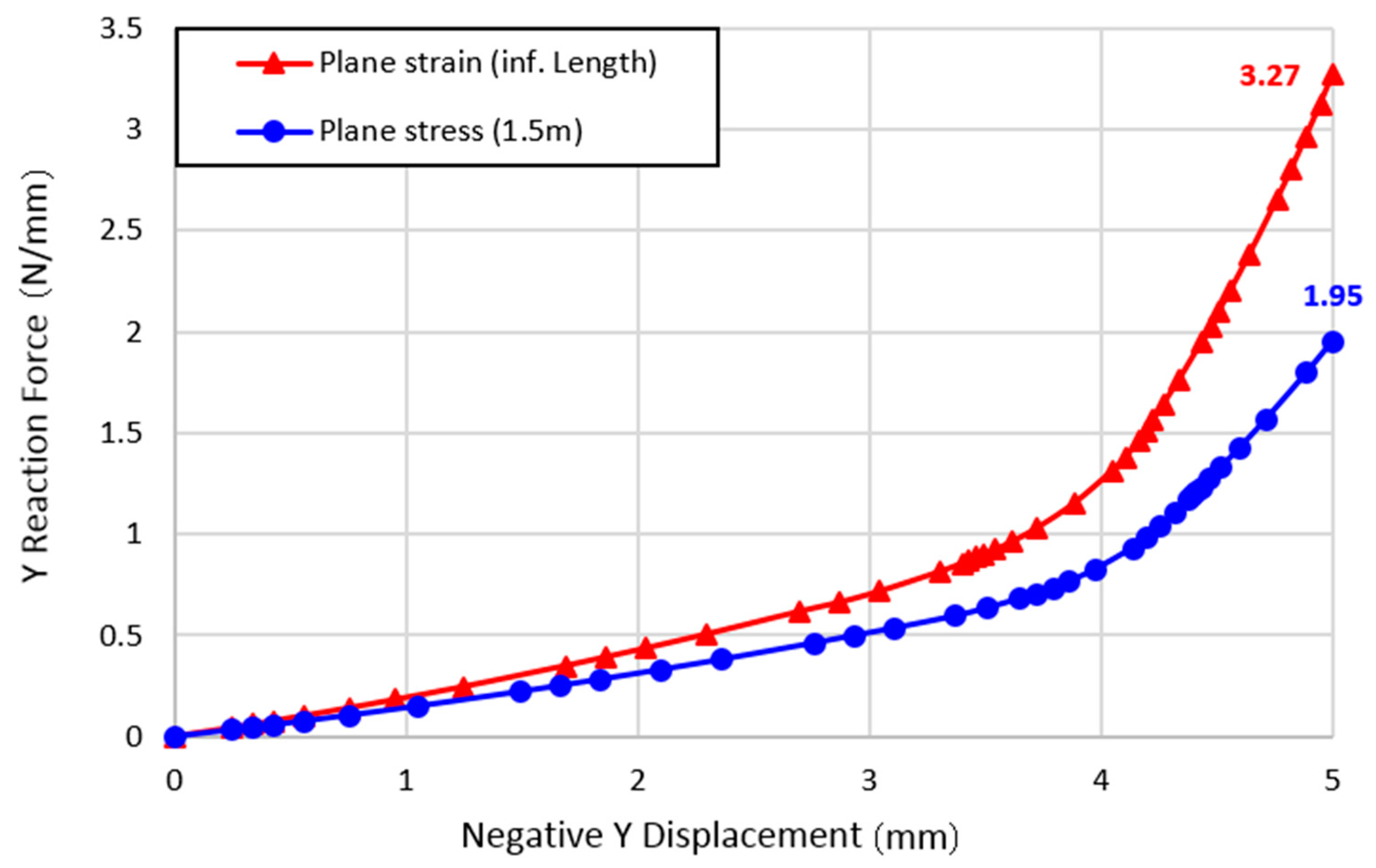
6.6. Plane Strain Assumption

A key assumption in the analysis is the plane strain assumption, which restricts any deformation (strain) out of plane. Under plane strain, the seal is assumed to extend over a long length of the façade. The plane strain assumption increases the effective stiffness of the material in-plane, which may result in a larger force required to achieve a −5 mm displacement as shown in Figure 10.
To assess the impact of this assumption, two cases are simulated and are presented in Figure 11:
(1)
Plane strain (infinite length).
(2)
Plane stress (1.5 m).
As expected, the plane stress assumption resulted in lower vertical load required to achieve a displacement of −5 mm (1.95 N/mm vs. 3.27 N/mm). The difference in loading between the plane strain and plane stress assumption is significant (40%).
Hence, for a conservative prediction, the following assumptions are used:
  • When predicting required vertical loading, use the plane strain assumption.
  • When testing waterproof performance with fluid penetrating pressure, use the plane stress assumption (This case is critical due to smaller contact area and contact pressure between the seal and top plate).

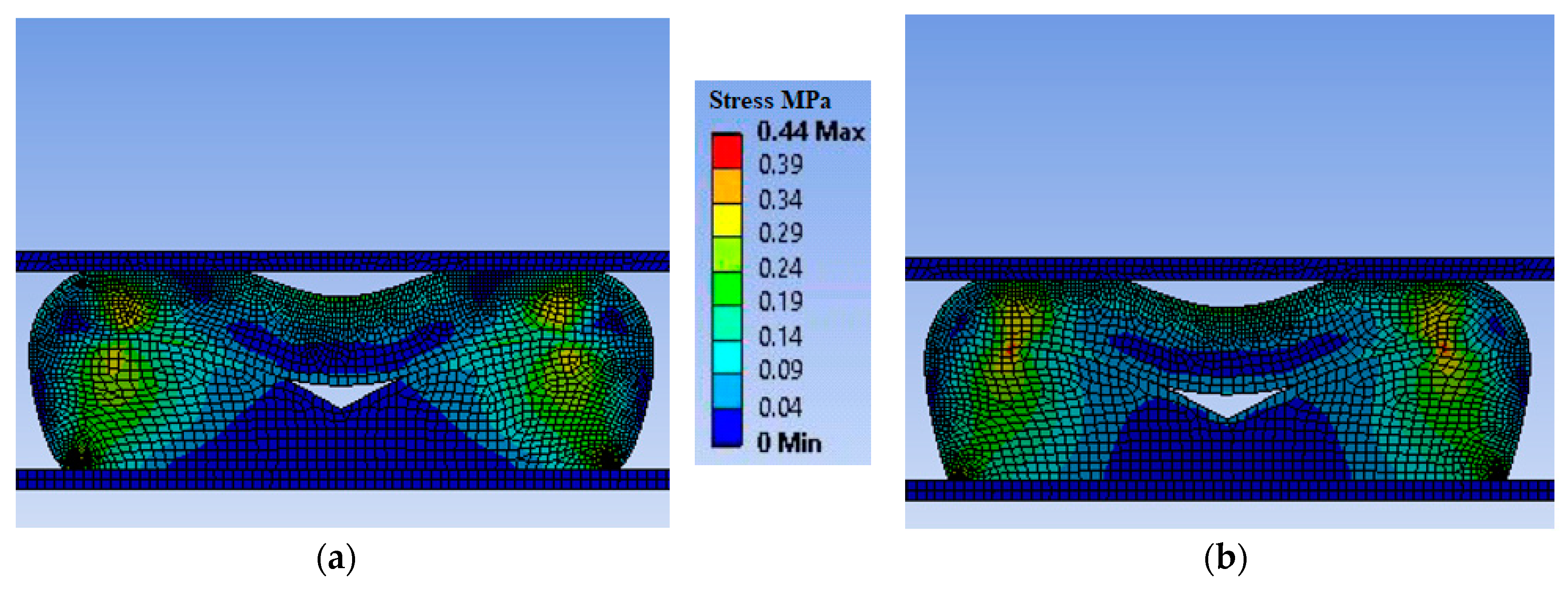
6.7. Frictional Effects

The friction coefficient (COF) of the EPDM seal and plate was not experimentally measured and is therefore unknown in this study. Studies in the literature suggest that the COF between a dry EPDM rubber and steel plate can be anywhere between 0.5–2.5 depending on multiple factors [33]. However, the COF may take lower values under wet conditions, or if lubrication is used for installing the seal.
To address this uncertainty, a number of simulations are performed with different friction values between the EPDM seal and plate. In all cases, the friction between EPDM and EPDM is assumed to be 0.1. The sensitivity of the results to each case are show in Figure 12.
Three friction cases are considered:
(1)
Frictionless, COF = 0.
(2)
COF = 0.1.
(3)
COF = 2.0.

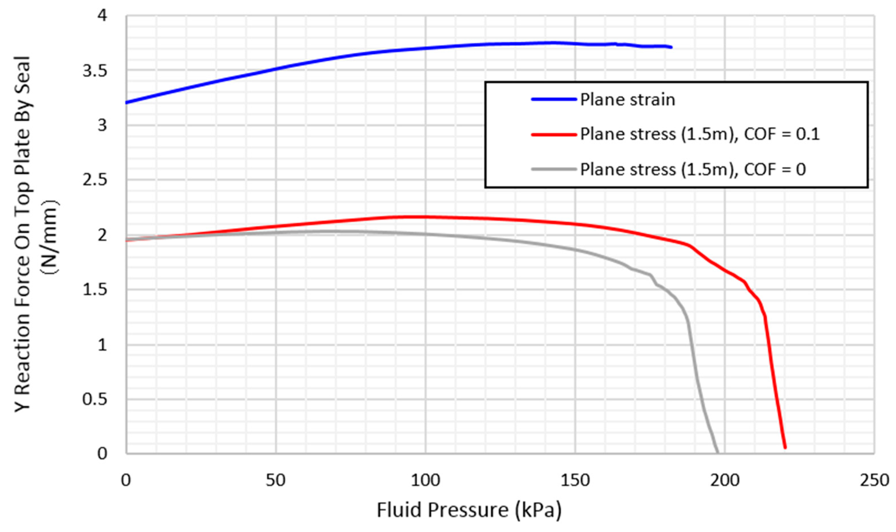
6.8. Fluid Pressure Penetration—Stage Two

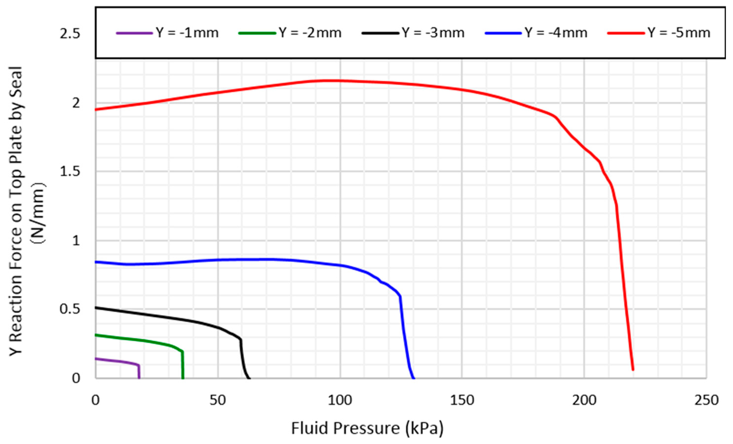
The second stage of the simulation involves applying a fluid pressure of increasing magnitude from one side of the seal. In this stage, a plane stress simulation is performed with a small COF = 0.1. The effect of modeling parameters on the pressure simulation is shown below.
The results from Figure 13 show that the maximum fluid pressure depends on the friction value between the seal and top plate. A lower COF resulted in lower maximum fluid pressure.
Figure 13 shows the performance of the rubber seal with increased fluid pressure. The y-axis represents the reaction force or the top façade from the rubber seal. A value of zero on the y-axis indicates that the seal has fully separated from the top plate, allowing for fluid to leak through.
The maximum fluid pressure supported by the seal is primarily dependent on the vertical compressive load (and consequent y displacement) applied on the seal. Hence, it is critical for waterproofing performance that the façade system applies adequate compressive load at all locations along the seal. Achieving a displacement of −5 mm would require a compressive force of up to 3.3 N per mm of seal length, this value needs to be verified with actual testing.
For the purpose of façade applications, the codes specify a maximum fluid pressure of 2.3 kPa. The results show that this criterion is met for all deflection values from −1 to −5 mm as shown in Figure 14.

6.9. Finite Element Summary

Using a non-linear FEA with a hyperelastic material, the performance of the EPDM rubber was tested in two stages. First, the seal is compressed vertically be −5 mm. Second, a penetrating fluid pressure is applied to one side of the seal.
The only mode of failure assumed is the separation of the EPDM seal at the top plate. The bonded contact with the bottom plate remains intact for all cases.
Under conservative assumptions (plane stress, frictionless contact) the FEA results suggest that the EPDM seal can adequately resist a constant fluid pressure of 2.3 kPa.
Limitations of the current mainly constitute uncertainty in modelling parameters, including the material model, plane stress/strain assumption, and friction coefficient. To address this, sensitivity studies were performed to assess the impact of these parameters on the final results. Additional testing would provide confidence in the numerical accuracy of the results.

7. Implementation

7.1. Small Scale

Tests for water penetration for varying compressions and pressures were carried out to understand the effect of tolerances in determining the robustness of the solution along with understanding the maximal sealing capacity.
Figure 15a shows the EPDM rubber gasket seal adhered to aluminium strip via tape adhesive and then sandwiched to the desired compression via the use of packers for measurement. Figure 15b shows a rubber boot seal is applied to the surface of the adjoined panel with waterproof silicone between the two members, this is then compressed and held tightly via screwed timber batons.
Tests were conducted on a pass/fail basis, pass being no observation of water ingress from the underside of the seal after 5 min of applied pressure and fail being the visibility of water ingress. At the design gap of 10 mm the gasket which has a depth of 15 mm is compressed 5 mm, the performance of the gasket in creating a water right seal cannot be faulted. At none of the increasing water pressure from 0 m of head to 2.8 m of head (27.5 KPa equivalent) did water penetration occur, this extremely positive result was in line with the finite element prediction as it well exceeded the 300 Pa minimum or 0.3 Ws (where Ws is the designed wind pressure) requirement by AS4284: Testing of Building Façades.
For robustness and fuller understanding this test was repeated on several developed samples of varying compression. The aim in doing these extra tests was to encapsulate the expected building tolerances which may be experienced onsite and to help further verify and validate the finite element model. Values between 2–3 mm either side of a 10 mm gap accounted for the tolerances were developed from material irregularities and manufacturing limitations. The tests on these panels with a gap width of 11 mm, 12 mm, 13 mm and 14 mm resulted in all but the final scenario with a compression of 1 mm reaching the maximum pressure available for testing of 2.8 m of head (27.5 KPa) without any sign of water penetration which is also in keeping with the finite elements predictions. The observation in the one configuration which water leakage was observed to occur (14 mm gap which is equivalent of 1 mm compression) was moisture build up and eventual droplet formation on the unadhered side of the gasket as expected.

7.2. Full Scale

The seal was used in a prefabrication construction project in collaboration with an industry partner. The project developed was a commercial premise constructed in a complete high level (closed panel complete with glazing and façade) prefabricated panelised form of construction as depicted in Figure 16a. The gasket solution was also used as a prefabricated element and installed in the factory offsite and acts as the principle sealing element between panel to panel vertical connections as shown in Figure 16b whilst a more traditional and easily implementable form of z-flashing was used for the horizontal joins.
The completed prefabricated wall panels are lifted and place into position whilst compressing the rubber gasket as shown in Figure 17a. The sealed joint after the completed lift and installation of the panel is shown Figure 17b.

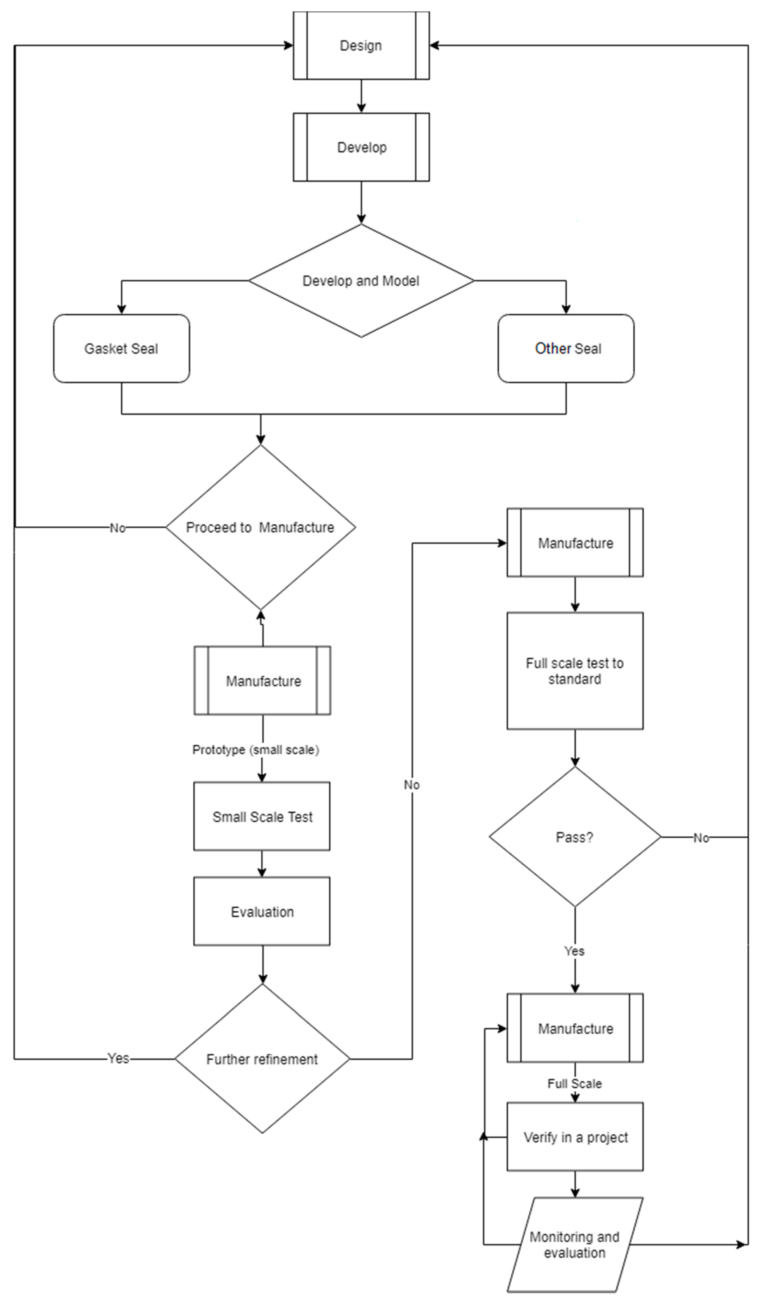
8. Monitoring and Evaluation

Once the seal was fully implemented and adopted for the case study project monitoring and evaluation was carried out to verify that at least in the short term to medium term that this is an appropriate solution which satisfies the design requirements and identifying and learning from any unknown or unexpected technicalities experienced in practical application. Figure 17b shows the due diligence taken in measurement of gap width between panels to compare with expected building tolerances and its compatibility with the seals required range of compression for adequate function. Additionally, assessment of the shape and condition of the seal from the external face along with the embedment depth along the height was noted. The wear and tear on the seal is primarily a function of the material properties, contact pressure, surface roughness but above all the duration of relative sliding movement [33]. Since the surface roughness of aluminum extrusion is low and the duration of the relative sliding movement only short as it only occurs during installation the wear and tear on the seal is to be low and confirmed onsite as no tearing or stretching/necking in the seal was observed. Furthermore long term wear and tear is expected to be minimal as all minor movements of the building during operation is easily taken up by the compression/expansion of the EPDM material.
The design criteria which can be captured in the short to medium term which were considered when inspecting and evaluating are; air tightness (not permeable to air even during high winds), water tightness (not permeable to water even during storm events), combined action of wind and rain (wind driven rain), notable sound transmission—airborne sound and structure-borne sounds, potential dust, dirt and grim buildup, chemical resistance against air pollution and cleaning products, allowance for tolerances (production, erection/assembly), deflection of components to bowing, allowance for drainage of runoff and infiltrated water and any damage during installation and/or transport. The result of the inspection and the open dialogue with the building occupants have led to confirmation of the performance of the gasket as a robust weather proofing solution meeting the aforementioned design criteria.
As monitoring and evaluation is a continual cycle as previously shown in Figure 5 the process is not over at any stage during the life of the building. There are some identified design objectives which can only be fully assured satisfactory attainment only after a long period of time, these include damage due to long term UV radiation which may lead to potential change in colour over time and potential change of stiffness over time, temperature and temperature change which may lead to the degradation of the rubber over time, humidity and change of humidity causing condensation and potential mould growth behind the seal, the effects of creep on the seal, differential movement of the foundation and its effect. These design objectives were not able to be evaluated at the current stage due to their primary potential presence in the long term such as long term UV exposure and due to difficulties in capturing the required information to be able to confidently mark successful satisfaction of design criteria for example difficulty to get in behind the seal or behind the inside face of the wall to check for potential mould growth.

9. Conclusions

A purpose specific weatherproof seal in the form of an EPDM rubber gasket has been presented for prefabricated panelised and modular systems. A full finite element analysis has been conducted on the compression of the gasket obtaining the stress profile and opposing reaction force necessary for levels of compression. From this a fluid dynamic computation has then been carried out of the compressed seal with an increasing water pressure on one side of the seal until the reactionary force of the seal reduces to zero indicating the penetration of water. The manufacturing process used to bring the final design of the gasket into reality has been detailed and outlined in the form of a flow chat. Building from this the implementation of the gasket seal in a real world scenario has been successfully carried out through its manufacturer and use in a case study project. The assembly of the seal on the prefabricated panels was carried out offsite and integrated into the closed panel manufacturing line with the installation of the fully complete panels on site proving successfully achievement of the goal of implementing a waterproofing solution between prefabricated elements without any onsite installation. Finally a short to medium term monitoring and evaluation was carried out which validated the real world practical effectiveness of a preinstalled gasket seal for waterproofing of vertical joints in prefabricated construction between each respected fully completed panel or module without the need for any onsite installation or access to the joint from the external face of the building thus removing the need for scaffolding in closed forms of prefabricated panelized and modular construction.

Author Contributions

Conceptualization, K.O., K.S. and P.M.; Data curation, K.O.; Formal analysis, K.O.; Funding acquisition, P.M.; Investigation, K.O.; Methodology, K.O.; Project administration, K.S. and P.M.; Resources, K.S. and P.M.; Software, K.O.; Supervision, K.S. and P.M.; Validation, K.O.; Visualization, K.O.; Writing—original draft, K.O.; Writing—review & editing, K.O.

Funding

This research was funded by the Australian Research Council (Project ID IC150100023).

Acknowledgments

The author would like to acknowledge the generous support provided by the University of Melbourne and Australian Research Council (Project ID: IC150100023).

Conflicts of Interest

The authors declare no conflict of interest. The funders had no role in the design of the study; in the collection, analyses, or interpretation of data; in the writing of the manuscript, and in the decision to publish the results.

References

  1. EMSEAL. Expansion Joints and Pre-Compressed Sealants; EMSEAL LLC: Woodbridge, ON, Canada, 25 January 2018. [Google Scholar]
  2. Lu, N. The current use of offsite construction techniques in the United States construction industry. In Proceedings of the Construction Research Congress 2009: Building a Sustainable Future, Seattle, WA, USA, 5–7 April 2009. [Google Scholar]
  3. NHBC. Modern Methods of Construction; Views from the industry; NHBC: Milton Keynes, UK, 26 June 2016. [Google Scholar]
  4. Gibb, A.G. Standardization and pre-assembly-distinguishing myth from reality using case study research. Constr. Manag. Econ. 2001, 19, 307–315. [Google Scholar] [CrossRef] [Green Version]
  5. Lopez, D.; Froese, T.M. Analysis of costs and benefits of panelized and modular prefabricated homes. Procedia Eng. 2016, 145, 1291–1297. [Google Scholar] [CrossRef]
  6. Yousif, A.A. Field Performance of Full Depth Precast Concrete Panels in Bridge Deck Reconstruction; University of Illinois at Chicago: Chicago, IL, USA, 1995. [Google Scholar]
  7. Issa, M.A.; Valle, C.L.R.D.; Abdalla, H.A.; Islam, S.; Issa, M.A. Performance of transverse joint grout materials in full-depth precast concrete bridge deck systems. PCI J. 2003, 48, 92–103. [Google Scholar] [CrossRef]
  8. De la Varga, I.; Munoz, J.; Bentz, D.P.; Stutzman, P.E.; Graybeal, B. Grout-concrete interface bond performance: Effect of interface moisture on the tensile bond strength and grout microstructure. Constr. Build. Mater. 2018, 170, 747–756. [Google Scholar] [CrossRef] [PubMed]
  9. Zhang, K.; Huang, H.; Duan, M.; Hong, Y.; Estefen, S.F. Theoretical investigation of the compression limits of sealing structures in complex load transferring between subsea connector components. J. Nat. Gas Sci. Eng. 2017, 44, 202–213. [Google Scholar] [CrossRef]
  10. BSFA. Weather Sealing of Buildings—The Impossible Dream? Seminar, Wednesday, June 27, 1984, Sydney, Australia; BSFA seminar; Building Science Forum of Australia: Sydney, Australia, 1984. [Google Scholar]
  11. Herzog, T.; Krippner, R.; Lang, W. Facade Construction Manual; Institut für Internationale Architektur-Dokumentation, Birkhauser: München, Germany, 31 January 2013; Volume 1, pp. 20–290. [Google Scholar]
  12. Stenti, A.; Moens, D.; Desmet, W. Dynamic modeling of car door weather seals: A first outline. In Proceedings of the ISMA 2004, Leuven, Belgium, 20–22 September 2004. Abstract ID 3891249-1262. [Google Scholar]
  13. Vlastos, A.E.; Gubanski, S. Surface structural changes of naturally aged silicone and EPDM composite insulators. IEEE Trans. Power Deliv. 1991, 6, 888–900. [Google Scholar] [CrossRef]
  14. Khan, Y.; Al-Arainy, A.A.; Malik, N.H.; Qureshi, M.I.; Al-Ammar, A.E. Loss and recovery of hydrophobicity of EPDM insulators in simulated arid desert environment. In Proceedings of the 2010 Asia-Pacific Power and Energy Engineering Conference (APPEEC), Chengdu, China, 28–31 March 2010. [Google Scholar]
  15. Gent, A.N. Engineering with Rubber: How to Design Rubber Components; Carl Hanser Verlag GmbH Co. KG: Munich, Germany, 6 August 2012. [Google Scholar]
  16. Shen, L.; Xia, L.; Han, T.; Wu, H.; Guo, S. Improvement of hardness and compression set properties of EPDM seals with alternating multilayered structure for PEM fuel cells. Int. J. Hydrogen Energy 2016, 41, 23164–23172. [Google Scholar] [CrossRef]
  17. Schwartz, T.A. Water in Exterior Building Walls: Problems and Solutions; ASTM: West Conshohocken, PA, USA, 1991. [Google Scholar]
  18. AS4284. AS 4284: 2008 Testing of Building Facades; Standards Australia: Sydney, Australia, 2008. [Google Scholar]
  19. ASTM D575. Standard Test Methods for Rubber Properties in Compression; ASTM International: West Conshohocken, PA, USA, 2018. [Google Scholar]
  20. ASTM D395. Standard Test Methods for Rubber Property—Compression Set; ASTM International: West Conshohocken, PA, USA, 2016. [Google Scholar]
  21. ASTM D412. Standard Test Methods for Vulcanized Rubber and Thermoplastic Elastomers—Tension; ASTM International: West Conshohocken, PA, USA, 2016. [Google Scholar]
  22. ASTM D897. Standard Test Method for Tensile Properties of Adhesive Bonds; ASTM International: West Conshohocken, PA, USA, 2016. [Google Scholar]
  23. ISO 6922. Adhesives—Determination of Tensile Strength of Butt Joints; Technical Committee: ISO/TC 61/SC 11 Products; International Organization for Standardization: Geneva, Switzerland, 23 August 1987. [Google Scholar]
  24. DIN EN-15870. Adhesives—Determination of Tensile Strength of Butt Joints; German Institute for Standardisation (Deutsches Institut für Normung): Berlin, Germany, 1 August 2009. [Google Scholar]
  25. ASTM C907. Standard Test Method for Tensile Adhesive Strength of Preformed Tape Sealants by Disk Method; ASTM International: West Conshohocken, PA, USA, 2017. [Google Scholar]
  26. ASTM-D1894. Standard Test Method for Static and Kinetic Coefficients of Friction of Plastic Film; ASTM International: West Conshohocken, PA, USA, 2014. [Google Scholar]
  27. ISO 15359. Determination of the Static and Kinetic Coefficients of Friction—Horizontal Plane Method; Technical Committee: ISO/TC 6/SC 2; International Organization for Standardization: Geneva, Switzerland, September 1999. [Google Scholar]
  28. Iveta, G.; Jozef, B. Hyperplastic material models and their applications in engineering. Appl. Mech. Mater. 2014, 611, 216–220. [Google Scholar]
  29. Ficková, M.; Bryksí, V.; Jelínek, P.; Beňo, J.; Mikšovský, F.; Adámková, E.; Horáček, J.; Chalupa, M.; Veverka, J.; Vlach, R.; et al. Strojírenská Technologie; 2013. Martin Novák, Univerzita J. E. Purkyně, Ústí nad Labem, Czech Republic. September 2013, Volume 18, Number 3. pp. 140–217. Available online: http://casopis.strojirenskatechnologie.cz/templates/obalky_casopis/XVIII_3_2013.pdf (accessed on 30 August 2018).
  30. Ogden, R.W. Non-Linear Elastic Deformations; Courier Corporation: North Chelmsford, MA, USA, 23 April 1997. [Google Scholar]
  31. ABAQUS. ABAQUS Benchmarks Manual; Version 6.6 Documentation; ABAQUS Inc.: Palo Alto, CA, USA, 2006. [Google Scholar]
  32. ANSYS. Release 17.2; ANSYS AIM™: Canonsburg, PA, USA, 2017. [Google Scholar]
  33. Karger-Kocsis, J.; Mousa, A.; Major, Z.; Bekesi, N. Dry friction and sliding wear of EPDM rubbers against steel as a function of carbon black content. Wear 2008, 264, 359–367. [Google Scholar] [CrossRef]
Figure 1. Gasket and jointing element sealing principles [11].
Buildings 08 00120 g001
Figure 2. Profile of the D-Shaped EPDM Gasket.
Buildings 08 00120 g002
Figure 3. High level overview flowchart of the method used.
Buildings 08 00120 g003
Figure 4. The manufacturing (and assembly) process.
Buildings 08 00120 g004
Figure 5. Material testing of EPDM rubber used for Gasket: (a) Uniaxial Compression; (b) Uniaxial Tension.
Buildings 08 00120 g005
Figure 6. EPDM material—Neo-Hookean hyperelastic model fitted to uniaxial experimental data.
Buildings 08 00120 g006
Figure 7. Geometry of the gasket seal before compression (Stage 1: Compression, Stage 2: Water Pressure).
Buildings 08 00120 g007
Figure 8. Y reaction force vs Negative Y displacement for three different mesh configuration.
Buildings 08 00120 g008
Figure 9. Geometry of the gasket seal after compression for identical loading cases: (a) Mesh A; (b) Mesh B; (c) Mesh C.
Buildings 08 00120 g009aBuildings 08 00120 g009b
Figure 10. Y reaction force vs. Negative Y displacement for the simulations.
Buildings 08 00120 g010
Figure 11. Contour plot of equivalent stress for simulations: (a) Plane Stress Assumption; (b) Plane Strain Assumption.
Buildings 08 00120 g011
Figure 12. Effect of surface friction on vertical reaction force for multiple displacements.
Buildings 08 00120 g012
Figure 13. Effect of modeling parameters on results.
Buildings 08 00120 g013
Figure 14. Waterproof performance of EPDM seal for a variety vertical displacement. Plane stress (1.5 m), COF = 0.1.
Buildings 08 00120 g014
Figure 15. Gasket Seal Water Penetration Testing (a) EPDM rubber gasket seal between testing panels; (b) A rubber boot seal to distribute water pressure to the gasket.
Buildings 08 00120 g015
Figure 16. Implementation with panelised form of prefabricated construction: (a) Commercial office building using the gasket seals; (b) EPDM gasket seal positions on the wall towards the outside face.
Buildings 08 00120 g016
Figure 17. Lifting and placement of panels: (a) Complete prefabricated wall panels are lifted and place into position whilst compressing the rubber gasket; (b) Due diligence in measurement of gap width and assessment of shape and embedment depth.
Buildings 08 00120 g017

