
Design, 3D FEM Simulation and Prototyping of a Permanent Magnet Spherical Motor


1
Department of Electrical Engineering, Yildiz Technical University, Istanbul 34220, Turkey
2
Numesys Inc., Istanbul 34758, Turkey
*
Author to whom correspondence should be addressed.
Actuators 2021, 10(11), 305; https://doi.org/10.3390/act10110305
Submission received: 28 October 2021
/
Revised: 18 November 2021
/
Accepted: 19 November 2021
/
Published: 21 November 2021
(This article belongs to the Special Issue Design and Application of Actuators with Multi-DOF Movement)
Abstract
:In recent years, large tilt angles, uniform magnetic flux distributions, strong forces, and large torques for motors have increasingly become important for robotics, biomedical, and automotive applications that have multi-degrees of freedom (MDOFs) motion. Generally, one-degree of-freedom motors are applied in MDOF motion. These situations cause the systems to have very complex and large structures. In order to address these issues, a 2-DOF surface permanent magnet spherical motor with a new mechanical design for the movement of the rotor with a large tilt angle of ±45° was designed, simulated, produced and tested in this paper. The motor consisted of a 4-pole permanent magnet rotor and a 3-block stator with 18 coils. In this study, the mechanical structure of the proposed spherical permanent magnet motor surrounded the rotor with two moving parts to move at a large tilt angle of ±45° without using any mechanical components such as spherical bearings, joint bearings, and bearing covers. Thus, the tilt angle, force, and torque values of the proposed motor have been improved according to MDOF motion motors using spherical bearings, bearing covers, or joint bearings in their mechanical structures in the literature. Ansys Maxwell software was used for the design and simulation of the motor. Three-dimensional (3D) finite element method (FEM) analysis and experimental studies were carried out on the force, torque, and magnetic flux density distribution of the motor. Then, simulation results and experimental results were compared to validate the 3D FEM simulations results.
1. Introduction
In recent years, with the development of robotics, biomedical, and automotive industries, the need for spherical motors, actuators, and manipulators that can perform motion with multi-degrees of freedom (MDOFs) has increased. Therefore, researchers have carried out studies on multi-axis motor designs with different structures and different operational performances, such as induction motors, ultrasonic motors, actuators, manipulators, and permanent magnet motors.
Williams and Laithwaite designed an induction motor with a spherical stator [1,2,3]. However, given the large dimensions of this induction motor, a new spherical motor with a spherical rotor was designed [4,5]. A three-degree-of-freedom (DOF) spherical manipulator [6,7] and MDOF force characterization system of soft actuators [8], a spherical actuator [9], and a fine motion wrist with six DOFs [10,11,12] were designed with large structures. Spherical MDOF motors with sphere and shell stator and rotor structures were designed [13,14,15,16,17,18,19,20]. It has been observed sphere and shell rotor and stator motor designs were caused by mechanical loads and frictions between the rotor and the stator.
Based on the previous studies, MDOF motors and actuators studies have been carried out using spherical bearings, bearing covers, and joint bearings in their mechanical structures to reduce mechanical loads and frictions and to improve the tilt angle motion.
A spherical actuator of which the stator includes 24 coils with 2 layers, and the rotor includes 8 permanent magnets and has a ±11° tilting angle by using bearings in the mechanical part. The outer stator radius of the actuator is 112.5 mm [21]. A spherical motor of which the rotor consists of 8-tiered-type permanent magnets, and a stator of which the outer diameter is 250 mm consists of 21 slots and has ±11.5° tilting angle. A joint bearing is used in the center of the rotor to support MDOF motions [22]. A spherical permanent magnet motor was designed, and the torque of the 4-phase system of the motor according to the change of the pole pitch angles obtained is about 25 mN·m when the tilt angle is 22.5° and the rotating angle is 0°. A spherical bearing is used to connect the rotor to the motor [23]. A spherical motor which consists of eight permanent magnets in the rotor and eight symmetrical coils in the stator was designed and verified by using three-dimensional (3D) finite element method (FEM) simulations. For the movement of the motor around the X-axis, Y-axis, and Z-axis, the coils rotating around the three axes have 450, 450, and 250 turns, respectively. The resistance of each coil for rotating around the X-axis and the Y-axis is 9.6 ohm, and the resistance of each coil for rotating around the Z-axis is 6.5 ohm. Each coil is excited with a current of 0.25 A. Power consumption was considered for the design. A spherical bearing is used to connect the rotor and the stator. The spherical motor has a tilt angle of ±25° along the X- and Y-axes and that of ±5° along the Z-axis. The average total torque output of the motor obtained is 7.98 mN·m in movements with a ±25° tilt angle [24]. A three-DOF voice coil motor that consists of a radially oriented ring magnet in the rotor and 16 coils in a stator was designed with the illustration of the structure, working principle, and simulation studies of the motor. For the movements of the motor around the X-axis, Y-axis, and Z-axis, the coils around these three axes have 500, 500, and 450 turns, respectively. Each coil is excited with a current of 1 A. Power consumption is considered for the electromagnetic structure design. A spherical bearing that is located at the center of the moving part is used to connect the moving and fixed parts. The proposed voice coil motor has a tilt angle of ±30° along the X- and Y-axes. The torque ranges of the motor obtained are between 14.08 mN·m and 19.40 mN·m from 0° to 30° tilt angles along the X-axis [25]. A spherical actuator consists of 16 permanent magnets in the rotor and 24 coils in the stator and has a ±37° tilting angle using a spacer and a shaft in the mechanical part. The resistances of all the coils are set to 2 ohm, and the loss obtained is 2 W [26]. A spherical joint that has a 1.08 N force for 2-DOF tilting movement was designed [27]. A spherical permanent magnets motor that has a tilt angle of ±30° along the X- and Y-axes and a rotation angle of ±360° along the Z-axis was designed with 4 drum-type permanent magnets. The outer stator radius of the motor was designed to be 90 mm. A shaft with a bearing cover is used in the mechanical design of the motor. The forces of the motor obtained are about 0.5 N in tilt movements and about 1 N in rotation movements [28,29,30,31]. The other spherical actuator that consists of 8 permanent magnets in the rotor and 16 air-cores coils in the stator was designed and has a ±11.5° tilting angle. The torque of the actuator obtained is 30.9 mN·m at ±11.5° tilting movements using a shaft component in the mechanical structure [32]. A three-DOF spherical motor was proposed with types of drum, butterfly, layered and series permanent magnets. The supporting shaft and bearing cover are used to connect the rotor to the motor [33]. A model consisting of a doubly excited spherical motor that has a 2-part stator with 12 windings and 4 permanent magnet rotors was investigated. A spherical bearing is used to connect the rotor to the motor. Electromagnetic and structural simulations were performed according to the motion capabilities of the spherical motor. After the simulations of the spherical motor were completed, it was tested with the prepared prototype and designed drive circuit. It was found that it can successfully perform 8 different motions from the starting position to the ±30° tilt motion position as revealed by the electromagnetic simulations [34,35].
In these studies, DOF motion motors and actuators were designed using spherical bearings, bearing covers, and joint bearings in their mechanical structures to provide tilting and rotational movement. However, it has been seen that the tilt motion capacities of the spherical bearings, bearing covers, and joint bearings are limited to the rotor movements and tilt motion angles of the MDOF motors and actuators. Therefore, the limited tilt motion angle of the motor also affects the torque and force values.
From the previous studies in the literature, it has been observed that there is a need to improve the tilt angle, force, torque, mechanical structure, and size of the motor for robotic, biomedical, and industrial applications that have MDOF motion. In order to address these issues and contribute to applications with 2-DOF motion, a spherical-surface permanent magnet motor with a 4-pole and 3-block stator having 18 coils has been designed and produced in this study. The stator part of the motor has been designed with three blocks to ensure the easy movement of the rotor in the mechanical structure with a large tilt angle and obtain higher torque and force values.
A new mechanical structure has been also designed for the proposed motor. This mechanical design surrounds the rotor with two moving parts to provide the movement of the rotor in the X- and Y-axes at a large tilt angle of ±45° without using any mechanical part elements such as spherical bearings, joint bearings, and bearing covers. These moving parts have been connected to each other with pins and integrated into the base with two fixed parts from their sides.
Furthermore, the force and torque values of the proposed motor have been improved thanks to the new mechanical structure compared to MDOF motion motors that use spherical bearings, bearing covers, or joint bearings in their mechanical structures.
3D simulations have been performed, before the motor was prototyped. The force, torque, and magnetic flux density of the motor have been obtained by 3D simulations with Ansys Maxwell using the FEM [36]. Then, the motor has been produced, and the experimental studies have been performed to obtain the magnetic flux density, force, and torque using a gaussmeter and a load cell. Finally, experimental studies have been compared and validated with 3D FEM simulations results.
2. Design of the Spherical Permanent Magnet Motor
2.1. Structure of the Motor
The design parameters and the sizing of a two-DOF spherical permanent magnet motor were determined by using the results of the study given in [37]. In that study, 27 different motor models were designed and simulated with different magnet materials, different magnet structures, and different stator–rotor structures. The spherical permanent magnet motor model suggested in [37] was taken as a baseline model in this study.
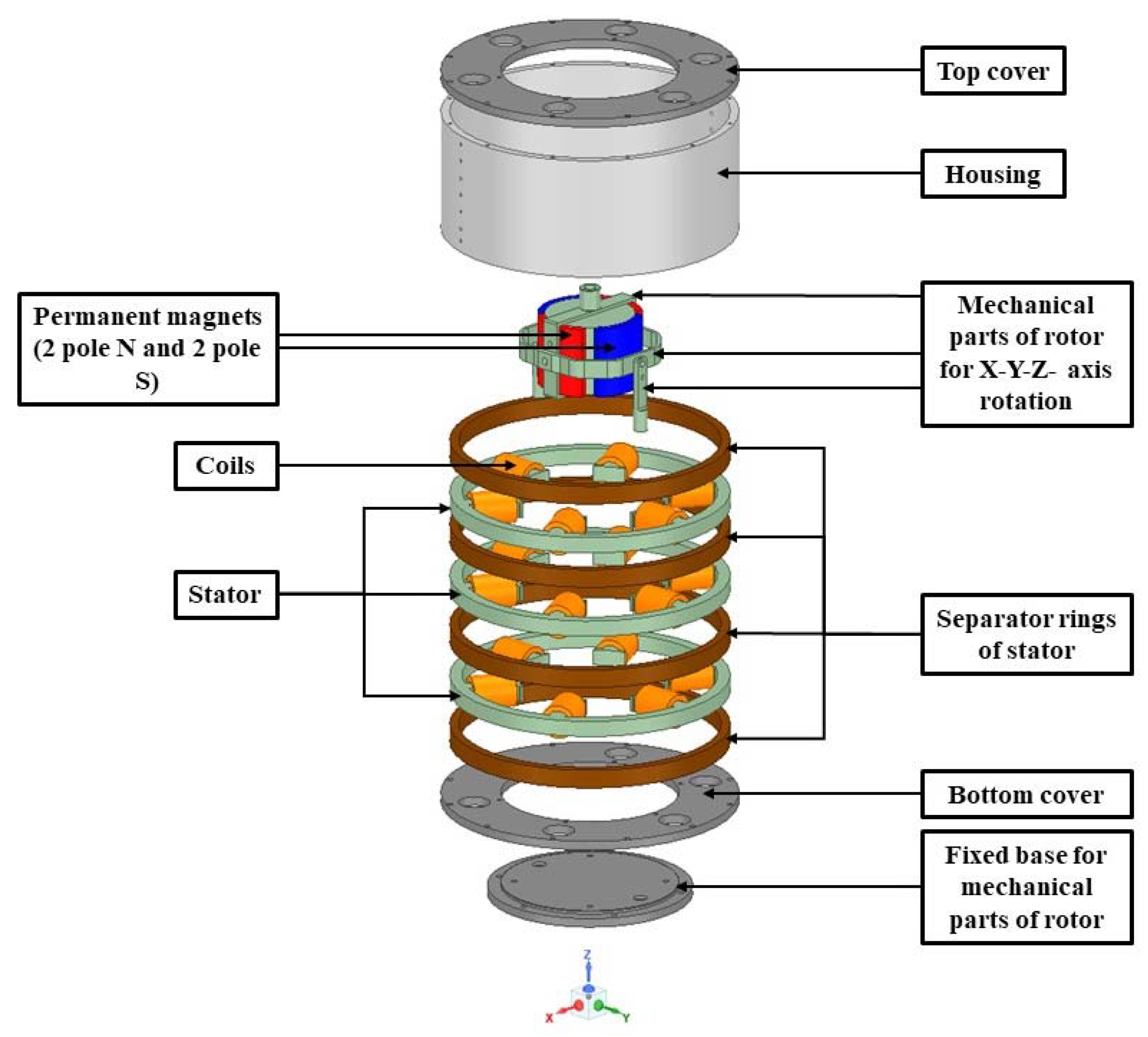
The 2-DOF spherical permanent magnet motor consisted of a rotor, a stator, and mechanical parts. The rotor consisted of radially oriented surface magnets and moving parts. Steel 1010 that had a high saturation flux density of approximately 2 T was used in the rotor. SmCo magnets were selected as the material of permanent magnets to provide the magnetic field of the rotor and have a residual magnetic flux density of 1.12 T. The stator consisted of 18 coils with 3 separate blocks and 4 separator rings. N020 electrical steel that had a low core loss of about 13 W/kg and a high electrical conductivity of 1,851,852 Siemens/m was used in the stator. Stainless steel was used as a non-magnetic material for the mechanical parts and the separator rings of the motor. The separator rings prevented the stator blocks from touching each other. The moving parts were connected by pins. The moving and fixed parts were connected to each other by the fixed base parts, which were located near the rotor. The motor model which is shown in Figure 1 was designed using Ansys Maxwell software.
2.2. Operating Principle of the Spherical Permanent Magnet Motor
The operating principle of the motor is based on the magnetic force generated by stator coils and permanent magnets. The same polarity of poles generates forces that push each other. The opposite polarity of poles produces magnetic forces that are pulled from each other. Thus, the magnetic forces generate a magnetic torque that allows the rotor to complete the motions around the X- and Y-axes.
In this study, the tilt angles of the 2-DOF permanent magnet spherical motor around the X-axis (α) and Y-axis (β) were ±45°. As shown in Figure 3, when upper coil 1 and lower coil 4 are both excited, S magnetic poles are produced. Similarly, upper coil 4 and lower coil 1 are excited, and then, N magnetic poles are produced. Thus, the motor performs a motion around the X-axis from 0° to 45°. As shown in Figure 4, when upper coils 2–3 and lower coils 5–6 are excited, N magnetic poles are produced. Similarly, upper coils 5–6 and lower coils 2–3 are excited, and then, S magnetic poles are produced. Thus, the motor performs a motion around the Y-axis from 0° to 45°. By changing the direction of the current, the motor can perform a motion in the reverse direction.
In addition, while the motor performs the movements around the X-and Y-axes, the power consumption is considered for electrical design. The power consumption can be expressed as [24,25]:
where is the current of the coil; is the resistance of the coil.
The coils were excited with a current of 1 A for the movements of the motor around the X-axis and the Y-axis. Each coil’s resistance was 0.167 ohm.
When the motor is rotating around the X-axis, the power consumption is expressed as [24,25]:
where is the power consumption when the motor is rotating around the X-axis; , , , and are the currents of upper coil 1, lower coil 4, upper coil 4, and lower coil 1, respectively.
When the motor is rotating around the Y-axis, the power consumption is expressed as [24,25]:
where is the power consumption when the motor is rotating around the Y-axis; , , , , , , and are the currents of upper coil 2, upper coil 3, lower coil 5, lower coil 6, upper coil 5, upper coil 6, lower coil 2, and lower coil 3, respectively.
In Equations (2) and (3), the currents of all coils are the same. In this way, Equations (2) and (3) can be expressed as [24,25]:
According to Equations (4) and (5), the power consumptions of the motor rotating around the X-axis and the Y-axis were determined as 0.667 W and 1.336 W, respectively.
When the motor is rotating around the X- and Y-axes, the total power consumption is expressed as [24,25]:
where is the sum of the power consumptions of the motor rotating around the X- and Y-axes.
According to Equation (6), the total power consumption of the motor rotating around the X-axis and the Y-axis was determined as 2.003 W.
3. Simulations of the Spherical Permanent Magnet Motor
FEM simulation software Ansys Maxwell was used to determine the magnetic field, force, and torque of the motor. Two cases were studied in the magnetic field calculations. In these two cases, the magnetic field distributions of the motor were calculated, when the motor was at no-load and load operating conditions. The other simulations were performed to calculate the force and the torque of the motor at load operating conditions.
3.1. Magnetic Field of the Motor under No-Load Operating Conditions
In the first case, the magnetic field distributions of the rotor and the stator were calculated, when the motor was at no-load. The rotor consisted of surface permanent magnets and had four permanent magnets, two N poles and two S poles. The model of the permanent magnet and the rotor is shown in Figure 5.
The flux density in a permanent magnet is composed of the flux in the air gap and the intrinsic magnetic induction. The flux density in a permanent magnet can be expressed as [15,36]:
where is the flux density of the permanent magnet magnetization; is the intrinsic magnetic induction; is the vacuum permeability; is the magnetic field.
The residual magnetic flux density of a permanent magnet is expressed as [15,36]:
where is the residual magnetic flux density; is the relative permeability of the permanent magnet; is the magnetic coercivity of the permanent magnet.
The material properties of the permanent magnet are given in Table 2.
The simulation results of the magnetic field distribution of the rotor and the stator when the motor was at no-load conditions are shown in Figure 6.
As can be seen from Figure 6, the distribution of the magnetic flux density was smooth, when the motor was at no-load conditions. Moreover, the average magnetic flux density distribution in the stator was determined as 0.67 T. It was observed that the magnetic flux vectors completed the circuit across the stator. The simulation results of the magnetic field in the air gap when the motor was at no-load conditions are shown in Figure 7.
As shown in Figure 7, the magnetic flux density in the air gap was homogenously distributed. The average magnetic flux density obtained in the air gap was 0.237 T. It has been seen that the magnetic flux density of the stator was due to the magnetic energy of the magnets in the rotor.
3.2. Magnetic Field of the Motor under Load Operating Conditions
In the second case, the magnetic field distributions of the motor for rotating around the X-axis (α) and the Y-axis (β) from 0° to ±45° were calculated separately. For the movements of the motor around the X-axis and the Y-axis, the coils were excited with a current of 1 A. Each of the coils in the stator consisted of 90 turns. Therefore, the coils were excited with 90 A turns of a magnetomotive force in the simulation. The magnetomotive force is expressed as [36]:
where is the magnetomotive force, is the number of turns of the coil, and is the load current of the coil.
When the motor was at load operating conditions, the simulation results of the magnetic field distributions of the motor at 0° and ±45° around the X-axis (α) and the Y-axis (β) are shown in Figure 8 and Figure 9, respectively.
As seen in Figure 8 and Figure 9, the magnetic flux density distributions of the motor under load conditions were uniform. There was no problem with magnetic saturation at the motor. In addition, the average magnetic flux density in the stator was determined to be about 1.1 T. When the motor was in a position of ±45° and rotated around the X-axis (α) and the Y-axis (β), it can be seen that the magnetic flux density increased as the rotor and stator approached each other. The simulation results of the magnetic field in the air gap with the motor loaded are shown in Figure 10.
As shown in Figure 10, when the motor was at loaded conditions, the maximum and the average magnetic flux densities in the air gap obtained were 0.403 T and 0.283 T in the X-axis from α = 0° to α = ±45°, respectively. When the motor was at loaded conditions, the maximum and the average magnetic flux densities in the air gap obtained were 0.36 T and 0.195 T in the Y-axis from β = 0° to β = ±45°, respectively.
3.3. Force and Torque of the Spherical Permanent Magnet Motor
The force and the torque of the motor can be determined using Ansys Maxwell 3D FEM software. In the electromechanical system, the force and the torque are generated by magnetic co-energy. The magnetic co-energy is expressed as [36]:
where is the magnetic co-energy; is the magnetic field; is the magnetic flux density.
Using the magnetic co-energy, the torque and the force are expressed as [36]:
where is the torque; is the force; is the current; is the rotating angle; is the direction of the displacement.
In this way, the simulation results of the torque and the force of the motor from 0° to 45°, rotating around the X-axis (α) and the Y-axis (β), with the motor loaded condition, are shown in Figure 11 and Figure 12, respectively.
As illustrated in Figure 11 and Figure 12, when the results of the simulation were examined, the average torque and force values obtained were 0.038 N·m and 1.92 N in the movement of the motor around the X-axis, respectively. As can be seen in Figure 12, the average torque and force values of the motor rotating around the Y-axis obtained were 0.027 N·m and 1.36 N, respectively.
4. Prototyping of the Spherical Permanent Magnet Motor
4.1. Stator of the Spherical Permanent Magnet Motor
The stator of the 2-DOF permanent magnet motor consisted of 18 coils and 3 separate blocks. Each of the coils consisted of 90 turns. N020 electrical steel was used for manufacturing the stator. The stator of the motor is shown in Figure 13.
4.2. Rotor of the Spherical Permanent Magnet Motor
The rotor had radially oriented surface magnets consisting of two N poles and two S poles. Steel 1010 was used for manufacturing the rotor, and SmCo was chosen as the permanent magnet material for the rotor. The rotor of the proposed motor is shown in Figure 14.
4.3. Mechanical Parts of the Spherical Permanent Magnet Motor
The mechanical parts of the motor consisted of covers, moving parts, fixed parts, a housing, and separator rings. There were 4 separator rings that prevented the stator blocks from touching each other. The moving parts were fixed to the rotor and provided the movement of the rotor in the X- and Y-axes. The material used for manufacturing the covers, moving parts, fixed parts, housing, and separator rings was chosen to be stainless steel. All mechanical parts and the motor are shown in Figure 15.
5. Testing of the Spherical Permanent Magnet Motor
5.1. Experimental Setup
Experimental studies on the magnetic flux density, force, and torque of the motor were conducted to verify, and the experimental results were compared with the simulations results. The magnetic field in the air gap of the motor was measured with a gaussmeter at no-load and load operating conditions. The forces were measured using a load cell [6,15,38,39,40]. The measuring capacity of the load cell was 50 N. The load cell which had an error sensitivity of 1% in force measurements was calibrated before the test. A weight was placed in the load cell, and the calibration factor was determined. Before testing, the initial values in the load cell were determined, and then all tests were performed. The force values were measured using the load cell and transferred to a computer with an HX711 signal amplifier module. The torque values were also determined using the measured forces with the force arm, which was positioned 0.02 m from the top to the center of the rotor [6,15,38]. The experimental setup for measuring the magnetic flux density and that for measuring the force and the torque of the motor are shown in Figure 16 and Figure 17.
5.2. Experimental Results of the Magnetic Flux Density in the Air Gap of the Motor at No-Load Conditions
Based on the results of the experimental studies and the simulation in the air gap, the magnetic flux density in the air gap of the motor at no-load conditions is shown in Figure 18.
As can be seen from Figure 18, when the motor was at no-load conditions, the measured maximum magnetic flux density distribution in the air gap was obtained to be 0.29 T based on the experimental studies. When the simulation and experimental results were examined, the average magnetic flux densities were obtained to be 0.237 T and 0.229 T in the air gap of the motor, respectively. When these results were compared, it was seen that the simulation results were as 97% accurate as the experimental results.
5.3. Experimental Results for Magnetic Flux Density in the Air Gap of the Motor at Load Conditions
According to the results of the experimental studies and the simulations of the magnetic flux density in the air gap of the motor from 0° to ±45° rotating around the X-axis (α) and the Y-axis (β) at load conditions are shown in Figure 19.
As seen in Figure 19, the experimental results of the maximum and average magnetic flux densities in the air gap of the motor at load conditions were determined to be 0.4 T and 0.256 T, respectively, in the X-axis from α = 0° to α = ±45°. In addition, the experimental results for the maximum and average magnetic flux densities were obtained to be 0.33 T and 0.158 T, respectively, at load conditions in the Y-axis from β = 0° to β = ±45°. When we compared the experimental results with the simulation results, it seemed that the simulation result of the average magnetic flux density in the air gap was as 90% accurate for the X-axis and as 81% accurate for the Y-axis as the experimental results.
5.4. Experimental Results for the Force and the Torque of the Motor
Based on the results of the measurements and simulations, the force and the torque of the motor from 0° to ±45° rotating around the X-axis (α) and the Y-axis (β) are shown in Figure 20 and Figure 21, respectively.
As illustrated in Figure 20, the average force results of the simulation and experiments for the motor rotating around the X-axis from 0° to ±45° obtained were 1.92 N and as 1.6 N, respectively. The average force results of the simulation and the experiments obtained were 1.36 N and 1.17 N, respectively, when the motor rotated around the Y-axis. The average torque results of the simulation and the experiments for the motor rotating around the X-axis from 0° to ±45° were also determined to be 0.038 N·m and 0.032 N·m, respectively, as seen in Figure 21. The average torque results of the simulation and the experiments were determined to be 0.027 N·m and 0.0236 N·m, respectively, when the motor rotated around the Y-axis.
6. Discussion
In this study, a surface permanent magnet 2-DOF spherical motor has been designed, manufactured and tested. First, the magnetic flux, force, and torque parameters of the motor have been simulated using the Ansys Maxwell tool. Then, the experimental studies have been carried out to validate the accuracy of the 3D FEM simulation results.
According to the experimental and simulation results, the magnetic flux densities under no-load and load operating conditions of the motor were in good agreement with each other. It is seen from the simulation results that the flux density was uniformly distributed in the air gap of the motor. The magnetic flux density parameters were also measured using a gaussmeter under both no-load and load conditions of the motor. It has been observed from the experimental studies that there was no magnetic saturation on the motor. It has been seen that the simulated average magnetic flux density was 3% higher than the experimental one at no-load operation conditions. Then, the maximum magnetic flux density values were also obtained in the X-axis and the Y-axis from 0° to ±45° at load conditions. When the motor rotated around the X-axis, the maximum magnetic flux density was 0.4 T. When the motor rotated around the Y-axis, the maximum magnetic flux density was 0.33 T. The experimental results were 1% and 8% lower than the simulation results for the X- and Y-axes, respectively.
In addition, the force and the torque of the motor have been obtained by experimental studies and compared with the simulation results. As a result, the average force values of the simulation and experimental studies for the motor rotating around the X-axis obtained were 1.92 N and 1.6 N, respectively. The average torque values of the simulation and experimental studies for the motor rotating around the X-axis were 0.038 N·m and 0.032 N·m, respectively. The results of the average force and torque of the motor rotating around the X-axis from 0° to ±45° have been examined, and the experimental results obtained were approximately 17% lower than the simulation results. The average force values of the simulation and experimental studies for the motor rotating around the Y-axis obtained were 1.36 N and 1.17 N, respectively. The average torque values of the simulation and experimental studies were 0.027 N·m and 0.0236 N·m, respectively in the movement of the motor rotating around the Y-axis. In addition, when the force and torque results for this case were examined, it was seen that the experimental results were approximately 14% lower than the simulation results.
The difference between the simulated and experimental force and torque values is due to the mechanical forces and friction at the connection points that provided the motion of the motor. However, it is predicted that the values of the force and torque can be significantly increased if the friction and mechanical loads are reduced around the mechanical connection points.
Considering previous studies [23,24,25,27,28,29,30,31,32] which are similar according to the working principle and structure of the motor with this study, it has been seen that the tilt angle motion capacities of the spherical bearings, bearing covers, and joint bearings limited the tilt motion angles between ±11° and ±37° of the MDOF motion motors and actuators. In addition, the average torque values of MDOF motion motors and actuators were obtained for tilt movements in the range of 7.98–19.40 mN·m in these studies [24,25]. The average force parameter has also been considered for the same studies and obtained for tilt movements in the range of 0.5–1.08 N [27,28,29,30,31].
It has been observed that the tilt angle was limited in MDOF motion spherical motors actuators using spherical bearings, bearing covers, and joint bearings for the mechanical structure. Thus, the limitation of the tilt angle also affects the force and torque values.
In this study, the mechanical structure of the prototyped motor was designed to improve the tilt angle, which is different from the mechanical structures of MDOF motion motors that consist of spherical bearings, joint bearings, or bearing covers in the literature.
Furthermore, the tilt angle of the prototyped motor of ±45° has been improved by 21% compared to tilt angles between ±11° and ±37° of MDOF motion motors by using spherical bearings, joint bearing, or bearing covers in their mechanical structures in the literature. Thus, the average force values for the motor with a tilt angle of ±45° have been obtained for movements in the X- and Y-axes to be 1.6 N and 1.17 N, respectively. The average torque values have been also obtained for the X- and Y-axes to be 32 mN·m and 23.6 mN·m, respectively. By increasing the tilt angle to ±45°, the average force and torque values of the prototyped motor obtained have been 29% and 43% higher than the MDOF motion motors that use spherical bearings, bearing covers, or joint bearings in their mechanical structures, respectively.
Additionally, the size also has been considered in the design of the prototyped motor. The outer diameter of the stator was 157 mm to ensure that the rotor easily moved in the new mechanical structure and achieved a large tilt angle of ±45°. The stator outer diameter has been found between 28 mm and 300 mm according to previous studies on MDOF motion motors and actuators [21,22,24,25,28,31] with the tilt motion angles between ±11° and ±37°. Power consumption has been also considered in this study. The power consumption of the proposed motor rotating around the X- and Y-axes with the tilt angle of ±45° was 2.003 W. The power consumption of the motor studied here seems to be lower within acceptable levels compared to those of other similar motor designs [24,25,26].
Although the size and the power consumption of the proposed motor are within the size and power consumption range of the previous studies on MDOF motion motors in the literature, a larger tilt angle and higher force and torque values have been achieved in this study.
7. Conclusions
A large tilt angle, a high torque, and a strong force values with a mechanical design are the most important features expected from MDOF motors. It has been observed that the inability to obtain high tilt angles depends not only on the electrical design of the motor, but also on the mechanical design of the motor that facilitates this movement. Therefore, both the electrical design and the mechanical structures of the motor have been designed by taking this case into account in this study.
A 2-DOF surface permanent magnet spherical motor that had a ±45° tilt angle around the X-axis (α) and the Y-axis (β) has been designed, simulated and prototyped in this study. The motor consisted of a 4-pole permanent magnet rotor and a 3-block stator with 18 coils. Ansys Maxwell software has been used for the 3D FEM simulation of the motor to determine the magnetic flux density, force, and torque. The simulated and experimental studies of the motor were compared for the motion around the X- and Y-axes from 0° to ±45°. In addition, a new mechanical structure of the proposed motor has been designed that surrounded the rotor with two moving parts to provide the movement of the rotor in the X- and Y-axes at a large tilt angle of ±45° without using any mechanical part elements such as bearing covers, spherical bearings, and joint bearings. Furthermore, the higher average force and torque values of the proposed motor with a tilt motion angle of ±45° obtained were 1.4 N and 27.8 mN·m, respectively. The literature offers narrower tilt angles typically between ±11° and ±37° compared to our wider range of ±45°. The force parameters were in a lower range of 0.5–1.08 N, and the torque values were in a lower range of 7.98–19.40 mN·m, compared to our results for the movements of the motor.
The power consumption and the size of the motor have been also considered in this study. The power consumption of the proposed motor rotating around the X- and Y-axes with a tilt angle of ±45° was 2.003 W. The outer diameter of the stator was determined to be 157 mm to ensure that the rotor rotated easily in the new mechanical structure with a large tilt angle of ±45°. It has been observed that the power consumption and the size of the proposed motor were within the size and the power consumption range of the previous studies in the literature, while a larger tilt angle and higher force and torques values have been achieved in this study.
Consequently, the tilt angle, force and torque values of the prototype spherical permanent magnet motor which has a new mechanical structure have been improved when we compared them to the MDOF motion motors that use spherical bearings, bearing covers, or joint bearings in their mechanical structures.
By using different materials and mechanical structures as a future work, the proposed motor can be improved in terms of force, torque, and motion capability and find wider applications in robotics, aerospace, automotive, and biomedical fields. In addition, the coils in the center block of the stator were actually designed suitable for 3-DOF motion capability. Thus, 3-DOF motion can also be obtained by developing a modified mechanical structure, so that it can be integrated into systems that require an even higher DOF.
Author Contributions
Conceptualization, U.Y.G. and S.Z.P.; methodology, U.Y.G. and S.Z.P.; software, U.Y.G.; validation, U.Y.G.; formal analysis, U.Y.G.; investigation, U.Y.G. and S.Z.P.; resources, U.Y.G. and S.Z.P.; writing—original draft preparation, U.Y.G.; writing—review and editing, S.Z.P.; visualization, U.Y.G. and S.Z.P.; supervision, S.Z.P. All authors have read and agreed to the published version of the manuscript.
Funding
This research received no external funding.
Institutional Review Board Statement
Not applicable.
Informed Consent Statement
Not applicable.
Data Availability Statement
Not applicable.
Acknowledgments
The authors of this article would like to thank the companies FEMSAN Electric Motors for the prototype of the motor; Numesys Inc. which is Ansys Elite Channel Partner for providing the Ansys Maxwell software; Figes Engineering and ADVENS Engineering for the experimental tests of the motor and all support during this study which is also based on the PhD thesis.
Conflicts of Interest
The authors declare no conflict of interest.
References
- Williams, F.; Laithwaite, E.; Piggot, L. Brushless variable speed induction motor. IEEE Proc. 1956, 2097U, 102–118. [Google Scholar]
- Williams, F.; Laithwaite, E.; Eastham, G.F. Development of design of spherical induction motor. IEEE Proc. 1959, 3036U, 471–484. [Google Scholar] [CrossRef]
- Laithwaite, E. Design of spherical motors. Electr. Times 1960, 9, 921–925. [Google Scholar]
- Vachtsevanos, G.J.; Davey, K.; Lee, K.M. Development of a novel intelligent robotic manipulator. IEEE Control. Syst. Mag. 1987, 7, 9–15. [Google Scholar] [CrossRef]
- Vachtsevanos, G.J.; Davey, K.R. Spherical Motor Particularly Adapted for Robotics. US Patent 4739241, 19 April 1988. [Google Scholar]
- Diep, B.T.; Nguyen, N.D.; Tran, T.T.; Nguyen, Q.H. Design and experimental validation of a 3-DOF force feedback system featuring spherical manipulator and magnetorheological actuators. Actuators 2020, 9, 19. [Google Scholar] [CrossRef] [Green Version]
- Li, X.; Bai, S.; Chen, W.; Liu, J. Torque modelling and current optimization of a spherical actuator built as an electromagnets driven spherical parallel manipulator. In Proceedings of the 2017 IEEE International Conference on Cybernetics and Intelligent Systems (CIS) and IEEE Conference on Robotics, Automation and Mechatronics (RAM), Ningbo, China, 19–21 November 2017; pp. 626–631. [Google Scholar]
- Joshi, S.; Paik, J. Multi-DoF force characterization of soft actuators. IEEE Robot. Autom. Lett. 2019, 4, 3679–3686. [Google Scholar] [CrossRef]
- Ahmadi, S.; Moghani, J.S.; Mirsalim, M. Simulation and analysis of a novel PM spherical 3-DOF actuator with E-shaped stator and blade-shaped rotor structure. In Proceedings of the 2018 9th Annual Power Electronics, Drives Systems and Technologies Conference (PEDSTC), Tehran, Iran, 13–15 February 2018; pp. 59–64. [Google Scholar]
- Hollis, R.L.; Salcudean, S.; Allan, A.P. A six degree of freedom magnetically levitated variable compliance fine motion wrist. In Proceedings of the 4th International Symposium on Robotics Research, Santa Cruz, CA, USA, 9–14 August 1987; MIT Press: Cambridge, MA, USA, 1988; pp. 65–73. [Google Scholar]
- Salcudean, S.E.; Hollis, R.L. A magnetically levitated fine motion wrist: Kinematics, dynamics and control. In Proceedings of the IEEE International Conference on Robotics and Automation, Philadelphia, PA, USA, 24–29 April 1988; pp. 261–266. [Google Scholar]
- Hollis, R.L.; Salcudean, S.E.; Allan, A.P. A six degree of freedom magnetically levitated variable compliance fine motion wrist: Design, modeling and control. IEEE Trans. Rob. Autom. 1991, 7, 320–332. [Google Scholar] [CrossRef]
- Wang, J.; Wang, W.; Jewell, G.W.; Howe, D. A novel spherical permanent magnet actuator with three degrees-of-freedom. IEEE Trans. Magn. 1998, 34, 2078–2080. [Google Scholar] [CrossRef]
- Wang, J.; Jewell, G.W.; Howe, D. Analysis, design and control of a novel spherical permanent magnet actuator. Proc. IEEE Electr. Power Appl. 1998, 145, 61–71. [Google Scholar] [CrossRef]
- Öner, Y. Computer Aided Three Dimensional Magnetic Analysis, Design and Application of a Permanent Magnet Spherical Motor. Ph.D. Thesis, University of Gazi, Ankara, Turkey, 2004. [Google Scholar]
- Li, H.; Li, T. End-effect magnetic field analysis of the Halbach array permanent magnet spherical motor. IEEE Trans. Magn. 2018, 54, 1–9. [Google Scholar] [CrossRef]
- Lu, B.; Aoyagi, M. Examination of an outer-rotor-type multidegree-of-freedom spherical ultrasonic motor. In Proceedings of the 2012 15th International Conference on Electrical Machines and Systems (ICEMS), Sapporo, Japan, 21–24 October 2012; pp. 1–5. [Google Scholar]
- Li, Z.; Chen, Q.; Yue, F.; Zhang, Y. Modal analysis of electromagnetic resonance for multi-degree-of-freedom spherical motor. In Proceedings of the 2018 21st International Conference on Electrical Machines and Systems (ICEMS), Jeju, Korea, 7–10 October 2018; pp. 1847–1852. [Google Scholar]
- Li, Z.; Chen, Q.; Wang, Q. Analysis of multi-physics coupling field of multi-degree-of-freedom permanent magnet spherical motor. IEEE Trans. Magn. 2019, 55, 1–5. [Google Scholar] [CrossRef]
- Li, B.; Li, Z.; Li, G. Magnetic field model for permanent magnet spherical motor with double polyhedron structure. IEEE Trans. Magn. 2017, 53, 1–5. [Google Scholar] [CrossRef]
- Yan, L.; Chen, I.-M.; Chee, K.L.; Yang, G.; Lin, W.; Lee, K.-M. Design and analysis of a permanent magnet spherical actuator. In Proceedings of the 2005 IEEE/RSJ International Conference on Intelligent Robots and Systems, Edmonton, AB, Canada, 2–6 August 2005; pp. 691–696. [Google Scholar]
- Gan, L.; Pei, Y.; Chai, F. Tilting torque calculation of a novel tiered type permanent magnet spherical motor. IEEE Trans. Ind. Electron. 2020, 67, 421–431. [Google Scholar] [CrossRef]
- Cho, S.; Lim, J.-S.; Oh, Y.J.; Jeong, G.; Kang, D.-W.; Lee, J. A study on output characteristics of the spherical multi-DOF motor according to the number of phases and pole pitch angles. IEEE Trans. Magn. 2018, 54, 1–5. [Google Scholar] [CrossRef]
- Liu, C.-S.; Lin, Y.-H.; Yeh, C.-N. Analytical Investigation on Torque of Three-Degree-of-Freedom Electromagnetic Actuator for Image Stabilization. Appl. Sci. 2021, 11, 6872. [Google Scholar] [CrossRef]
- Lin, Y.-H.; Liu, C.-S.; Yeh, C.-N. Design and Simulation of Novel 3-DOF Spherical Voice Coil Motor. Actuators 2021, 10, 155. [Google Scholar] [CrossRef]
- Takahara, K.; Hirata, K.; Niguchi, N.; Nishiura, Y.; Sakaidani, Y. Experimental evaluation of the static characteristics of multi-degree-of-freedom spherical actuators. IEEE Trans. Magn. 2017, 53, 1–5. [Google Scholar]
- Han, Y.M.; Choi, S.B. Force-feedback control of a spherical haptic device featuring an electrorheological fluid. Smart Mater. Structures 2006, 15, 1438–1446. [Google Scholar] [CrossRef]
- Li, Z. Magnetic-field computation of a novel 3-DOF deflection-type PM motor with analytical and finite-element methods. Elektrotehniški Vestn. 2014, 81, 51–56. [Google Scholar]
- Li, Z.; Zhang, L.; Lun, Q.; Jin, H. Optimal design of multi-DOF deflection type PM motor by response surface methodology. J. Electr. Eng. Technol. 2015, 10, 965–970. [Google Scholar] [CrossRef] [Green Version]
- Li, Z.; Lun, Q.Q. Analysis of magnetic field and levitation force characteristics for 3-DOF deflection type PM motors. J. Chin. Inst. Eng. 2016, 39, 704–712. [Google Scholar] [CrossRef]
- Li, Z.; Wang, Q. Levitation mechanism and improvements of 3-DOF deflection type PM actuator. IEEE Trans. Appl. Supercond. 2016, 26, 1–5. [Google Scholar] [CrossRef]
- El-Khalafawy, K.; El-Amary, N.H. Spherical actuator design and operation based on magnetic profile. In Proceedings of the 2017 IEEE PES Asia-Pacific Power and Energy Engineering Conference (APPEEC), Bangalore, India, 8–10 November 2017; pp. 1–6. [Google Scholar]
- Li, Z.; Yu, X.; Xue, Z.; Sun, H. Analysis of Magnetic Field and Torque Features of Improved Permanent Magnet Rotor Deflection Type Three-Degree-of-Freedom Motor. Energies 2020, 13, 2533. [Google Scholar] [CrossRef]
- Gündoğar, U.Y. Magnetics, Mechanical Analysis and Implementation of Double Excited Spherical Motor. Master’s Thesis, University of Pamukkale, Denizli, Turkey, 2015. [Google Scholar]
- Gündoğar, U.Y.; Zorlu Partal, S.; Öner, Y. 3D electromagnetic and structural analysis of a doubly excited spherical motor for robotic applications. In Proceedings of the 2020 Innovations in Intelligent Systems and Applications Conference (ASYU), Istanbul, Turkey, 15–17 October 2020; pp. 1–8. [Google Scholar]
- Ansys Maxwell 2021 R2; Ansys, Inc.: Canonsburg, PA, USA, 2021.
- Gündoğar, U.Y.; Zorlu Partal, S. The effect of using different magnet structures and different magnet materials on the design of the spherical motor. Eur. J. Sci. Technol. 2020, 19, 946–959. [Google Scholar]
- Wen, Y.; Li, G.; Wang, Q.; Tang, R.; Liu, Y.; Li, H. Investigation on the Measurement Method for Output Torque of a Spherical Motor. Appl. Sci. 2020, 10, 2510. [Google Scholar] [CrossRef] [Green Version]
- Rossini, L.; Chételat, O.; Onillon, E.; Perriard, Y. Analytical and experimental investigation on the force and torque of a Reaction Sphere for satellite attitude control. In Proceedings of the 2011 IEEE/ASME International Conference on Advanced Intelligent Mechatronics (AIM), Budapest, Hungary, 3–7 July 2011; pp. 487–492. [Google Scholar]
- Omura, M.; Shimono, T.; Fujimoto, Y. Development of semicircular tubular core-less linear motor and its motion control. IEEJ Trans. Ind. Appl. 2015, 135, 246–257. [Google Scholar] [CrossRef]
Figure 1.
The design of the spherical permanent magnet motor.

Figure 2.
Structures of the motor stator with coils (a), separator rings and stator blocks (b), the rotor with permanent magnets (c), fixed base and moving parts (d), and a housing and covers (e).
Figure 2.
Structures of the motor stator with coils (a), separator rings and stator blocks (b), the rotor with permanent magnets (c), fixed base and moving parts (d), and a housing and covers (e).

Figure 3.
The working principle for the motor rotating around the X-axis: (a) top view of the rotor that is at α = 45°; (b) YZ cross-section view of the rotor that is at α = 45°.
Figure 3.
The working principle for the motor rotating around the X-axis: (a) top view of the rotor that is at α = 45°; (b) YZ cross-section view of the rotor that is at α = 45°.

Figure 4.
The working principle for the motor rotating around the Y-axis: (a) top view of the rotor that is at β = 45°; (b) XZ cross-section view of the rotor that is at β = 45°.
Figure 4.
The working principle for the motor rotating around the Y-axis: (a) top view of the rotor that is at β = 45°; (b) XZ cross-section view of the rotor that is at β = 45°.

Figure 5.
Model of surface permanent magnets and the rotor.

Figure 6.
Magnetic field distributions of the motor under no-load conditions: (a) magnetic field vectors from the top view of the motor; (b) magnetic field distribution from the isometric view of the motor.
Figure 6.
Magnetic field distributions of the motor under no-load conditions: (a) magnetic field vectors from the top view of the motor; (b) magnetic field distribution from the isometric view of the motor.

Figure 7.
Magnetic field distributions in the air gap of the motor under no-load conditions: (a) magnetic field distribution in the air gap from the top view of the motor; (b) magnetic field distribution in the air gap of the motor.
Figure 7.
Magnetic field distributions in the air gap of the motor under no-load conditions: (a) magnetic field distribution in the air gap from the top view of the motor; (b) magnetic field distribution in the air gap of the motor.

Figure 8.
Magnetic field distributions of the motor at loaded conditions rotating around the X-axis: (a) view of the motor that is at α = 0°; (b) view of the motor that is at α = +45°; (c) view of the motor that is at α = −45°.
Figure 8.
Magnetic field distributions of the motor at loaded conditions rotating around the X-axis: (a) view of the motor that is at α = 0°; (b) view of the motor that is at α = +45°; (c) view of the motor that is at α = −45°.

Figure 9.
Magnetic field distributions of the motor at loaded conditions rotating around the Y-axis: (a) view of the motor that is at β = 0°; (b) view of the motor that is at β = +45°; (c) view of the motor that is at β = −45°.
Figure 9.
Magnetic field distributions of the motor at loaded conditions rotating around the Y-axis: (a) view of the motor that is at β = 0°; (b) view of the motor that is at β = +45°; (c) view of the motor that is at β = −45°.

Figure 10.
Magnetic flux density distributions in the air gap of the motor under loaded conditions rotating around the X-axis from α = 0° to α = ±45° (a) and rotating around the Y-axis from β = 0° to β = ±45° (b).
Figure 10.
Magnetic flux density distributions in the air gap of the motor under loaded conditions rotating around the X-axis from α = 0° to α = ±45° (a) and rotating around the Y-axis from β = 0° to β = ±45° (b).

Figure 11.
Force values of the motor at the loaded condition rotating around the X-axis from α = 0° to α = ±45° (a) and rotating around the Y-axis from β = 0° to β = ±45° (b).
Figure 11.
Force values of the motor at the loaded condition rotating around the X-axis from α = 0° to α = ±45° (a) and rotating around the Y-axis from β = 0° to β = ±45° (b).

Figure 12.
Torque values of the motor in the loaded condition rotating around the X-axis from α = 0° to α = ±45° (a) and rotating around the Y-axis from β = 0° to β = ±45° (b).
Figure 12.
Torque values of the motor in the loaded condition rotating around the X-axis from α = 0° to α = ±45° (a) and rotating around the Y-axis from β = 0° to β = ±45° (b).

Figure 13.
Stator and coils of the motor.

Figure 14.
Rotor and permanent magnets of the motor.

Figure 15.
Mechanical parts of motor.

Figure 16.
The gaussmeter device and the motor for the measurements of magnetic flux density.

Figure 17.
Experimental setup for the measurements of forces and torques.

Figure 18.
Measured and simulation results of the magnetic flux density in the air gap of the motor at no-load conditions.
Figure 18.
Measured and simulation results of the magnetic flux density in the air gap of the motor at no-load conditions.

Figure 19.
Measured and simulation results of the magnetic flux density in the air gap of the motor rotating around the X-axis from α = 0° to α = ±45° (a) and rotating around the Y-axis from β = 0° to β = ±45° (b).
Figure 19.
Measured and simulation results of the magnetic flux density in the air gap of the motor rotating around the X-axis from α = 0° to α = ±45° (a) and rotating around the Y-axis from β = 0° to β = ±45° (b).

Figure 20.
Measured and simulation results for force values of motor rotating around X-axis from α = 0° to α = ±45° (a) and rotating around the Y-axis from β = 0° to β = ±45° (b).
Figure 20.
Measured and simulation results for force values of motor rotating around X-axis from α = 0° to α = ±45° (a) and rotating around the Y-axis from β = 0° to β = ±45° (b).

Figure 21.
Measured and simulation results for the torque values of the motor rotating around the X-axis from α = 0° to α = ±45° (a) rotating around the Y-axis from β = 0° to β = ±45° (b).
Figure 21.
Measured and simulation results for the torque values of the motor rotating around the X-axis from α = 0° to α = ±45° (a) rotating around the Y-axis from β = 0° to β = ±45° (b).


Table 1.
Design parameters of the motor.
| Symbol | Corresponding Parameter | Dimension |
|---|---|---|
| Sod | Stator’s outer diameter | 157 mm |
| Sid | Stator’s inner diameter | 84 mm |
| Rod | Rotor’s outer diameter | 50.7 mm |
| SRid | Separator ring’s inner diameter of the stator | 147 mm |
| PMt | Permanent magnet’s thickness | 4.15 mm |
| SRt | Separator’s ring thickness | 10.5 mm |
| St | Stator’s thickness | 9 mm |
| RPMl | Rotor’s length | 40 mm |
| Cl | Connector’s length | 12.5 mm |
| MPod | Mechanical part’s outer diameter | 71.5 mm |
| TBCid | Top and bottom cover’s inner diameter | 100 mm |
| TBCod | Top and bottom covers’ outer diameter | 167 mm |
| HTBCl | Housing and top-bottom cover’s length | 79 mm |
| Hl | Housing’s length | 69 mm |
| FBl | Fixed base’s length | 5 mm |
Table 2.
Material properties of the permanent magnet.
| Parameter | Value |
|---|---|
| Residual magnetic flux density | 1.12 T |
| Relative permeability of the permanent magnet | 1.08 |
| Magnetic coercivity of the permanent magnet | 814.567 kA/m |
Publisher’s Note: MDPI stays neutral with regard to jurisdictional claims in published maps and institutional affiliations. |
© 2021 by the authors. Licensee MDPI, Basel, Switzerland. This article is an open access article distributed under the terms and conditions of the Creative Commons Attribution (CC BY) license (https://creativecommons.org/licenses/by/4.0/).
Share and Cite
MDPI and ACS Style
Gündoğar, U.Y.; Zorlu Partal, S. Design, 3D FEM Simulation and Prototyping of a Permanent Magnet Spherical Motor. Actuators 2021, 10, 305. https://doi.org/10.3390/act10110305
AMA Style
Gündoğar UY, Zorlu Partal S. Design, 3D FEM Simulation and Prototyping of a Permanent Magnet Spherical Motor. Actuators. 2021; 10(11):305. https://doi.org/10.3390/act10110305
Chicago/Turabian StyleGündoğar, Umut Yusuf, and Sibel Zorlu Partal. 2021. "Design, 3D FEM Simulation and Prototyping of a Permanent Magnet Spherical Motor" Actuators 10, no. 11: 305. https://doi.org/10.3390/act10110305
Note that from the first issue of 2016, this journal uses article numbers instead of page numbers. See further details here.