
Position Soft-Sensing of Direct-Driven Hydraulic System Based on Back Propagation Neural Network
by
 , ,
, ,
Shuzhong Zhang
1,2 ,
,
Tianyi Chen
1,
Tatiana Minav
3,
Xuepeng Cao
4,*,
Angeng Wu
1,
Yi Liu
1 and
Xuefeng Zhang
1 1
Fujian Key Laboratory of Intelligent Machining Technology and Equipment, Fujian University of Technology, Fuzhou 350108, China
2
Engineering Research Center of Advanced Energy Saving Driving Technology, Ministry of Education, Chengdu 610031, China
3
Faculty of Engineering and Natural Sciences, ATME, Innovative Hydraulics and Automation, Tampere University, 33014 Tampere, Finland
4
Key Laboratory of Expressway Construction Machinery of Shaanxi Province, Xi’an 710064, China
*
Author to whom correspondence should be addressed.
Actuators 2021, 10(12), 322; https://doi.org/10.3390/act10120322
Submission received: 5 November 2021
/
Revised: 24 November 2021
/
Accepted: 1 December 2021
/
Published: 5 December 2021
(This article belongs to the Section Precision Actuators)
Abstract
:Automated operations are widely used in harsh environments, in which position information is essential. Although sensors can be equipped to obtain high-accuracy position information, they are quite expensive and unsuitable for harsh environment applications. Therefore, a position soft-sensing model based on a back propagation (BP) neural network is proposed for direct-driven hydraulics (DDH) to protect against harsh environmental conditions. The proposed model obtains a position by integrating velocity computed from the BP neural network, which trains the nonlinear relationship between multi-input (speed of the electric motor and pressures in two chambers of the cylinder) and single-output (the cylinder’s velocity). First, the model of a standalone crane with DDH was established and verified by experiment. Second, the data from batch simulation with the verified model was used for training and testing the BP neural network in the soft-sensing model. Finally, position estimation with a typical cycle was performed using the created position soft-sensing model. Compared with the experimental data, the maximum soft-sensing position error was about 7 mm, and the error rate was within ±2.5%. Furthermore, position estimations were carried out with the proposed soft-sensing model under differing working conditions and the errors were within 4 mm, but the periodically cumulative error was observed. Hence, a reference point is proposed to minimize the accumulative error, for example, a point at the middle of the cylinder. Therefore, the work can be applied to acquire position information to facilitate automated operation of machines equipped with DDH.
1. Introduction
In order to meet the increasing energy efficiency requirements and adapt to dangerous and harsh environments, intelligent and autonomous have become the main development trend of heavy-duty or construction machinery [1]. In hydraulic systems, pump-controlled cylinder systems are increasingly proposed in academia and have attracted industry attention due to high energy efficiency, compactness, and low cost compared with valve-controlled systems. Therefore, this trend provides the opportunity to implement sensorless position control systems for hydraulic cylinders using virtual sensors. The benefits of using virtual sensors include increased redundancy and reduced reliance on expensive position sensors typically used in hydraulic cylinders [2,3,4].
Hydraulic system monitoring, fault diagnosis, position control dangerous, etc. are inseparable from the displacement signal of the hydraulic cylinder. The current displacement measurement technology can be divided into contact measurement and non-contact measurement [5].
Contact measurement refers to the installation of displacement sensors on the actuators. The installation position can be inside or outside the hydraulic cylinder such as magnetostrictive displacement sensors, potentiometers, variable inductance sensors, draw-wire sensors, grating displacement sensors, and other displacement sensors [6,7,8]. For internal installation, it usually needs to drill holes in the cylinder rod, which will increase the cost and difficulty of installation and maintenance. For external installation, the sensors are equipped on the surface of the hydraulic cylinder, which is less expensive and easier to install. However, the external sensors are more vulnerable to pollution and damage in harsh environments, which would deteriorate their reliability and life span [9,10,11].
Non-contact measurement includes the methods based on photoelectric, electromagnetic, and other technologies without contacting the measured object. Non-contact measurement can be classified into visual measurement and non-visual measurement. Non-visual measurement mainly includes inertial measurement, global positioning system, wireless LAN, and other methods [12]. Vision measurement is a new non-contact measurement technology derived from computer vision. In this method, a camera is used to collect the image of the manipulator, and the position information is computed through the algorithm [13,14]. However, the two main obstacles of using vision-based methods are resolution and limited frame rate, both of which reduce the dynamic performance of displacement capture [15].
At present, the displacement signal in the hydraulic system is mainly obtained by contact measurement. Due to the drawbacks of contact measurement, the research of virtual sensors has attracted more and more attention. In 2010, Minav et al. [16] used the designed algorithm to estimate the load and height of the moving target on a forklift and then calculated the required rotational number of the electric motor. In the research, the displacement of the hydraulic cylinder was obtained by estimating the cumulative flow output from the pump to the hydraulic cylinder. Therefore, only the motor speed signal is required to realize the position control of the hydraulic cylinder. The research results showed that the maximum position error was 1.8%. In 2014, Minav et al. [17] researched the sensorless position control of a direct-driven hydraulic system. Taking a micro-crane as a test case, the maximum error was 3% under varying loads, speeds, and cycles. In 2017, Sourander, Minav et al. [4] established a two-dimensional table of temperature, speed, and displacement, and estimated the position of the boom and bucket hydraulic cylinder of a mining loader by combining table lookup and calculation. In 2018, Siavash et al. [18] performed a preliminary study on the position control of a multi-actuator without a displacement sensor on an excavator, with a maximum error of about 5 cm. Gradl and Plockinger et al. [19,20] carried out a study on position or speed control without displacement sensors and proposed a stepping hydraulic cylinder, which controlled the oil intake and discharge of two small driven cylinders by switching valves to realize the stepping of the main hydraulic cylinder, with a position accuracy of 0.17%. However, this needs to redesign the loop, and more valve sets are required. In 2021, Zhang et al. [21] developed the displacement soft-sensing method of a pump-controlled cylinder driven by a servo motor, realized indirect measurement of hydraulic cylinder displacement using motor speed and torque signals, and corrected the leakage coefficient to improve the accuracy.
In light of the fact that sensorless rotor position control has been widely studied in electric drives, in particular, the back propagation (BP) neural network is widely used in electric motors [22,23,24]. Both electric motor and hydraulic systems are nonlinear systems, thus using the BP neural network with arbitrary nonlinear mapping ability can realize multi-input single-output operations. Hence, this research proposed a position soft-sensing model based on the BP neural network for direct-driven hydraulics (DDH).
The rest of this paper is divided into five sections. In Section 2, modeling and verification of a crane with DDH are presented. Section 3 describes the soft-sensing model based on a BP neural network, where Section 3.1 depicts the principle of position soft-sensing, Section 3.2 obtains the training and test data, and Section 3.3 trains and tests the BP neural network. Section 4 verifies the position soft-sensing model by the measured data. In Section 5, simulations are carried out with the verified model, where Section 5.1 and Section 5.2 present a simulation of two cycles with varying loads and demonstrate the cumulative error under multi-cycles, and Section 5.3 proposes a method to eliminate the cumulative error. Section 6 draws the conclusions.
2. Modelling and Verification of a Crane with DDH
Section 2.1 illustrates the modeling of a crane with DDH. Section 2.2 validates the created model by measurement.
2.1. Modeling
In this research, a standalone crane was chosen as the test case. The crane was equipped with a direct-driven hydraulic system as shown in Figure 1. Figure 2 shows the schematic diagram of the direct-driven hydraulic system. In the system, two external gear motors driven by a permanent magnet synchronous motor coaxially are used as bi-directional pump/motors. One of the hydraulic accumulators is used as a tank and the other is not in use (cut off by a ball valve). Two pressure sensors and one position sensor were utilized to collect data to validate the simulation in the next step. Additionally, two check-valves were installed for anti-cavitation and two pressure relief valves for safety.
Table 1 shows the parameters of the main components of the DDH.
2.2. Model Verification
To verify the feasibility of the built crane model with DDH, a test was performed with a load of 40 kg. In the test, the cylinder extended and retracted two times with a displacement of about 300 mm using open-loop position control. In addition, the measured rotational speed of the electric motor in Figure 5 was used as the reference input to the model in Figure 4. Moreover, the displacement and two pressures of the cylinder from measurement and simulation are presented and compared. Figure 6 shows the simulated and measured displacement curves and Figure 7 shows the error of displacement. Figure 8 and Figure 9 illustrate the pressures of the two sides of the cylinder.
In Figure 7, it can be seen that the maximum position error was 6 mm (about 2%), occurring at the maximum displacement point. Additionally, Figure 8 and Figure 9 illustrate that the simulated and measured pressure levels are acceptable. Hence, the comparison result between the simulation and measurement demonstrates that the accuracy of the crane model is acceptable. In this case, the built model can be used to produce batch data under differing working conditions for the training of the BP neural network and test the performance of the proposed soft-sensing model in the next step.
3. Position Soft-Sensing Model Based on BP Neural Network
Section 3.1 illustrates the principle of the proposed position soft-sensing method. Section 3.2 demonstrates the preparation of the data for training and testing of the BP neural network. Furthermore, Section 3.3 presents the training and testing of the neural network.
3.1. Principle of Position Soft-Sensing
The proposed position sensing model computes the velocity using BP neural network and integrates the velocity to obtain the position, as shown in Figure 10.
In the DDH, the velocity of the cylinder depends on its in- and out-flow rates. Additionally, these flowrates are determined by the flowrates from or to the pumps, the nonlinear leakages of pumps and cylinder, and volume changes of the oil due to pressure change, temperature, and rotational speed [27]. In this research, the temperature of the system was assumed to be constant, namely, the viscosity of the fluid was unvaried and did not affect the leakage of the system. Hence, the velocity of the cylinder had a nonlinear relationship with the pressures of the cylinder and the speed of the electric motor. The neural network simulates the processing of information by the human brain and has a strong self-learning ability. In various industrial application scenarios, for nonlinear problems, the neural network is an effective solution to such problems [28]. The development of a neural network provides new ideas and methods for hydraulic cylinder displacement estimation [29]. Therefore, a position soft-sensing model using the BP neural network was proposed for DDH and its principle diagram is shown in Figure 11.
The structure of the BP neural network for velocity estimation is shown in Figure 12. This research adopted a 3-layer BP neural network including three input nodes, 10 hidden layer nodes, and one output node. The training function is traingdx, the hidden layer neuron transfer function is tansig, and the output layer neuron transfer function is logsig.
3.2. Training and Testing Data Preparation
In order to produce enough data for BP neural network training and testing, a batch simulation was performed using the created crane model. Figure 13 displays the reference speed for the electric motor, a sinusoidal signal f1(t) = 550 sin(2πt/15)t. Meanwhile, according to the capability of the crane, 11 loads were used for the batch simulation (from 0 to 250 kg with an interval of 25 kg). In this way, the simulation can generate data covering a wide range of velocities under varying loads and rotational speeds.
Furthermore, the data required for the neural network training and testing were obtained by batch simulation. Pressures of the cylinder chambers pA and pB are shown in Figure 14 and Figure 15, and the corresponding velocities in Figure 16.
The effect of load on the pressures of the two chambers can be observed in Figure 14 and Figure 15, where the pressures increased with the heavier loads. The three local magnifications in Figure 16 show that the heavier load, the greater the speed fluctuation. Finally, 33,000 groups of data were obtained from the simulation for the training and testing of the BP neural network.
3.3. Training and Testing the BP Neural Network
The 33,000 groups of data were randomly classified into a training set (25,000 groups) and a testing set (8000 groups). A five-point numerical differentiation and normalization of the sample data were performed, and then the offline training of the BP neural network was conducted. Since the velocity was in the order of 1 mm/s, to ensure accuracy, the training accuracy was set to 10−3 mm/s and the number of training was 10,000 times. The predicted and expected values of each point of the BP neural network and errors are shown in Figure 17.
To evaluate the training results of the BP neural network, the coefficient of determination (R2), mean square error (MSE), and root mean square error (RMSE) were used as the evaluation indexes. R2 represents the goodness-of-fit of the regression fitting curve, and the value was between 0 and 1 (the closer to 1 the greater goodness-of-fit). MSE represents the Euclidean distance between the predicted value and the true value. Smaller MSE means that the predicted value is closer to the true value. RMSE represents the stability of the prediction error and can be used to investigate whether the prediction model can make stable and accurate predictions, where the smaller the better.
R2, MSE, and RMSE are defined as follows:
where is the expected value; is the predicted value; and is the average of the expected value. z is the number of test data groups.
The training results in Figure 17 illustrate that small errors occurred about every 1500 groups. The pressure fluctuated when the hydraulic cylinder was around the zero position. The motor speed signal was set according to the expected displacement, which is a sinusoidal signal. Hence, the velocity of the cylinder computed by the neural network is similar to a harmonic signal, the derivative of the expected displacement. Three sets of velocity were computed respectively including groups 0–2000 with a load of 200 kg during 10–30 s, 2001–5000 with a load of 225 kg during 0–30 s, and 5001–8000 with a load of 250 kg during 0–30 s. Finally, the data of the three sets were put together to form a curve, similar to a sinusoidal, as shown in Figure 17. This phenomenon affects the training, but, from an overall point of view, the index (R2 = 0.99986, MSE = 6.3886 × 10⁻⁵, and RMSE = 0.0080, calculated in mm) demonstrates that the performance of the trained BP neural network was good.
The mean square errors of the training set, validation set, test set, and the overall set varied with the number of training images, as shown in Figure 18. Each stage of BP neural network training is demonstrated in Figure 19. The correlation analyses of each sample set and the whole are presented in Figure 20.
It can be seen from Figure 18, Figure 19 and Figure 20 that the target value of MSE was quite different from the best value, but it can be seen from other parameters that the neural network was well trained. Additionally, the weights of the trained BP neural network are listed as follows:
, , ,
4. Verification of Position Soft-Sensing Model
To verify the position soft-sensing model, the measured data from the previous experiment were utilized as inputs to the model including the measured pressures of the cylinder chambers, the rotational speed of the electric motor, and the initial position of the cylinder. Figure 21 and Figure 22 illustrate the positions from the soft-sensing model and measurement and the errors after comparison.
The training data for the BP neural network from thee simulation but not the measurement affects the accuracy of the proposed position soft-sensing model. It can be seen from Figure 22 that soft-sensing errors were within ±2.5% and the maximum error was 7 mm, occurring at 45 s. The comparison results show that the proposed soft-sensing model is feasible and has acceptable accuracy for further simulations.
5. Simulation and Accumulative Error Correction
To further verify the feasibility and accuracy of the proposed model, simulations and comparisons were performed. Considering the influence of different loads and motor speeds on the soft-sensing, three loads (50 kg, 120 kg, and 200 kg) and two types of reference speed (sinusoidal and typical working cycle) were utilized for the simulations.
5.1. Sinusoidal Working Cycle with Varying Loads
Figure 23 displays the sinusoidal cycle f2(t) = 410 sin(2πt/30)t under three loads (50 kg, 120 kg, and 200 kg). The given motor speed signal and load were input into the simulation model of the crane. At the same time, the pressure of two chambers and motor speed were extracted and then used as input to the position soft-sensing model. Figure 24 shows the soft-sensing positions and simulated positions. Furthermore, Figure 25 shows that the soft-sensing error was within ±3 mm.
Additionally, the error curves shifted downward with the increase in load, caused by the greater leakage under heavier load. It can be seen that the error trend in the first cycle (0~30 s) was basically the same as the second one (30~60 s), but accumulated errors can be observed at 30 s and at 60 s (the end of each cycle).
5.2. Typical Cycle with Varying Loads
Figure 26 displays the typical motor speed signal (similar to the reference speed in the experiment) under three loads (50 kg, 120 kg, and 200 kg) [30]. After simulation and position soft-sensing, Figure 27 and Figure 28 present the positions of soft-sensing and simulation and error. The comparison results demonstrate that the errors were within ±3 mm.
In Figure 28, the phenomenon of error accumulation was also observed at the end of each cycle. This is because the soft-sensing method first predicts the velocity and then integrates it. In the prediction process, there is a velocity prediction error first, and then there is a cumulative error in the integration process. Such a double-layer error will result in a cumulative error, as shown in Figure 25 and Figure 28. Hence, it is necessary to eliminate or minimize the accumulative error.
5.3. Accumulative Error Correction
Since the accumulative error will inevitably occur in the integration process, this research proposes setting reference points using proximity sensors, for example, at the middle of the cylinder [16]. Hence, when the displacement of the hydraulic rod reaches the midpoint, the accumulative error will be reset to zero.
The hydraulic cylinder stroke is 400 mm, so the reference point was set at 200 mm, which means that the hydraulic cylinder rod position will be reset when it reaches 200 mm. Using the proposed accumulative error correction, the soft-sensing errors of the sinusoidal and the typical cycle in Section 4 decreased significantly, as shown in Figure 29 and Figure 30.
It can be seen from Figure 29 that after the minimization of cumulative error, a whole cycle was observed from 9.12 to 39.12 s, and the trend of the previous cycle is repeated in 39.12–60 s. The error is approximately periodic and within 3 mm. Similarly, it can be seen from Figure 30 that the period from 8.51 to 38.51 s was a whole cycle, and the trend of the previous cycle was repeated in the period from 38.51 to 60 s. In addition, the error was within 4 mm. This method showed an error far less than the error of the soft measurement method in reference [4].
To further verify the performance of using a middle reference point, simulation and position soft-sensing were carried out under a multi-cycle sinusoidal signal with a load of 40 kg, as shown in Figure 31. The soft-sensing position with and without correction are shown in Figure 32. Figure 33 presents the errors.
It can be seen from Figure 33 that after correcting the accumulated error, the error curve becomes periodic and the error remains stable with high accuracy. This is because a proximity switch is set at the midpoint of the stroke. Therefore, the integration process will restart whenever the midpoint is reached, which limits the infinite amplification of the accumulated error and the max error rate drops to 1%.
6. Conclusions
Aiming at addressing the disadvantages of the physical position sensor of utilization in automation, a position soft-sensing model based on BP neural network was proposed to estimate the cylinder position. DDH was selected as a test case. The simulation model of a crane with DDH was established and validated by experiment. The BP neural network was created and trained with the data from batch simulation using the validated crane model. Furthermore, the viability of the proposed soft-sensing model was verified by experiments and simulations under varying reference signals and loads. As the accumulative error occurs, a reference point was proposed to minimize the accumulative error under multi-cycle operation.
- The verification and simulations results show that the proposed position soft-sensing model for DDH had an accuracy within 7 mm and 4 mm, respectively, and the error rate was within 2.5%.
- Due to the notable accumulative error under multi-cycle, setting reference points can minimize the error accumulation. For example, when applying a middle reference point, the max error rate drops to 1%.
Further steps will entail an experimental validation of the proposed method for position control. In order to improve the accuracy of the proposed virtual sensor, more information from sensors can be utilized such as fluid temperature and additional pressure.
Author Contributions
Conceptualization, S.Z., T.C. and T.M.; Methodology, S.Z. and T.C.; Software, T.C., A.W. and Y.L.; Validation, S.Z. and T.C.; Formal analysis, S.Z. and T.C.; Investigation, S.Z., T.C., A.W., Y.L. and X.Z.; Resources, S.Z., T.M. and X.C.; Writing—original draft preparation, T.C. and S.Z.; Writing—review and editing, S.Z., X.C. and T.M.; Visualization, S.Z.; Supervision, T.M. and X.C.; Project administration, S.Z.; Funding acquisition, S.Z. All authors have read and agreed to the published version of the manuscript.
Funding
This research was funded by the Key Laboratory of Expressway Construction Machinery of Shaanxi Province (No. 300102251508); the Natural Science Foundation of Fujian Province, China (No. 2021J011051); the Program for Innovative Research Team in Science and Technology in Fujian Province University (IRTSTFJ); and the Industry-Academy Cooperation Project of Fujian Province (No. 2020H6025).
Acknowledgments
Special thanks to Thales Agostini (Federal University of Santa Catarina, Florianópolis, Brazil) for providing the experimental data utilized for the model validation.
Conflicts of Interest
The authors declare no conflict of interest.
References
- Yang, H. Progress and Trend of Construction Machinery Intelligence. Constr. Mach. Technol. Manag. 2018, 31, 36–37. [Google Scholar]
- Zhang, S.; Minav, T.; Matti, P.; Huang, H. Performance Comparison between Single and Double Pump Controlled Asymmetric Cylinder under Four-quadrant Operation. Trans. Chin. Soc. Agric. Mach. 2018, 49, 409–419. [Google Scholar]
- Lee, S.; Hong, Y. A dual EHA system for the improvement of position control performance via active load compensation. Int. J. Precis. Eng. Manuf. 2017, 18, 937–944. [Google Scholar] [CrossRef]
- Tom, S.; Matti, P.; Minav, T.; Henri, H. Sensorless position estimation of simulated direct driven hydraulic actuators. In Proceedings of the 15th Scandinavian International Conference on Fluid Power, SICFP’17, Linköping, Sweden, 7–9 June 2017. [Google Scholar]
- Li, Y.; Fan, R.; Yang, L.; Zhao, B.; Quan, L. Research Status and Development Trend of Intelligent Excavators. J. Mech. Eng. 2020, 56, 165–178. [Google Scholar]
- Herceg, E.E. Taking a position on hydraulic cylinder sensors. Hydraul. Pneum. 2015, 68, 24. [Google Scholar]
- Lagozzino, S.; Simic, M.; Dudkiewicz, D. Development of a novel system for linear displacement sensor calibration. Energy Procedia 2019, 160, 519–525. [Google Scholar] [CrossRef]
- Staff, D.W. Magnetostrictive Sensor: Sizing and Applying. Available online: https://www.designworldonline.com/magnetostrictive-sensor/ (accessed on 30 September 2021).
- Hua, H.; Liao, Z.; Wu, X.; Chen, Y. A Bezier-based state calibrating method for the low-cost potentiometer with inherent nonlinearity. Measurement 2021, 178, 109325. [Google Scholar] [CrossRef]
- Danaee, S.; Nurmi, J.; Minav, T.; Mattila, J.; Pietola, M. Direct Position Control of Electro-Hydraulic Excavator. In Proceedings of the BATH/ASME 2018 Symposium on Fluid Power and Motion Control, Bath, UK, 27 July 2018. [Google Scholar]
- Wang, T.; Wang, Q.; Chen, Z. Sensorless Speed Tracking Control of PMSG Applied in Hydraulic Power Regeneration; IEEE: Budapest, Hungary, 2011; pp. 832–837. [Google Scholar]
- Rybarczyk, D. Application of the MEMS Accelerometer as the Position Sensor in Linear Electrohydraulic Drive. Sensors 2021, 21, 1479. [Google Scholar] [CrossRef] [PubMed]
- Liang, C.J.; Lundeen, K.M.; McGee, W.; Menassa, C.C.; Lee, S.; Kamat, V.R. A vision-based marker-less pose estimation system for articulated construction robots. Autom. Constr. 2019, 104, 80–94. [Google Scholar] [CrossRef]
- Xu, J.; Yoon, H. Vision-based estimation of excavator manipulator pose for automated grading control. Autom. Constr. 2019, 98, 122–131. [Google Scholar] [CrossRef]
- Park, J.; Moon, D.; Yoon, H.; Gomez, F.; Spencer, B.F., Jr.; Kim, J.R. Visual-inertial displacement sensing using data fusion of vision-based displacement with acceleration. Struct. Control Health Monit. 2018, 25, e2122. [Google Scholar] [CrossRef]
- Minav, T.A.; Laurila, L.I.E.; Pyrhønen, J.J. Relative position control in an electro-hydraulic forklift. Int. Rev. Autom. Control 2013, 1, 54–61. [Google Scholar]
- Minav, T.; Bonato, C.; Sainio, P.; Pietola, M. Direct Driven Hydraulic Drive. In Proceedings of the 9th International Fluid Power Conference, Aachen, Germany, 24–26 March 2014. [Google Scholar]
- Danaee, S.; Minav, T.; Pietola, M. Sensorless Position Control For Electro-Hydraulic System—A technological status review. In 2018 Global Fluid Power Society PhD Symposium (GFPS); IEEE: Samara, Russia, 2018; pp. 1–6. [Google Scholar]
- Plöckinger, A.; Gradl, C.; Scheidl, R. High Accuracy Sensorless Hydraulic Stepping Actuator. In Proceedings of the Eighth Workshop on Digital Fluid Power (DFP 2016), Tampere, Finland, 24–25 May 2016. [Google Scholar]
- Gradl, C.; Plöckinger, A.; Scheidl, R. Sensorless position control with a hydraulic stepper drive—Concept, compression modeling and experimental investigation. Mechatronics 2016, 35, 91–101. [Google Scholar] [CrossRef]
- Zhang, S.; Zhang, L.; Liu, X.; Zhang, X. Soft-sensing Method for Cylinder Position of Pump-controlled System. Chin. Hydraul. Pneum. 2021, 45, 116–120. [Google Scholar]
- Zhu, H.; Lei, Y.; Xiaoyan, D. Displacement Sensorless Operation Control of Bearingless Permanent Magnet Synchronous Motor Based on BP Neural Network Left Inverse. Proc. CSEE 2020, 40, 3673–3681. [Google Scholar]
- Sun, X.; Chen, L.; Jiang, H.; Yang, Z.; Chen, J.; Zhang, W. High-Performance Control for a Bearingless Permanent-Magnet Synchronous Motor Using Neural Network Inverse Scheme Plus Internal Model Controllers. IEEE Trans. Ind. Electron. 2016, 63, 3479–3488. [Google Scholar] [CrossRef]
- Xiao, J.F.; Xiao, Q.M. Control of Switched Reluctance Motors based on Improved BP Neural Networks. Recent Adv. Electr. Electron. Eng. 2018, 11, 97–102. [Google Scholar]
- Agostini, T.; De Negri, V.; Minav, T.; Pietola, M. Effect of Energy Recovery on Efficiency in Electro-Hydrostatic Closed System for Differential Actuator. Actuators 2020, 9, 12. [Google Scholar] [CrossRef] [Green Version]
- Järf, A. Flow Compensation Using Hydraulic Accumulator in Direct Driven Hydraulic Differential Cylinder Application and Effects on Energy Efficiency. Master Thesis, Aalto University, Helsinki, Finland, 2016. [Google Scholar]
- Pourmovahed, A.; Beachley, N.H.; Fronczak, F.J. Modeling of a Hydraulic Energy Regeneration System: Part I—Analytical Treatment. J. Dyn. Syst. Meas. Control 1992, 114, 155–159. [Google Scholar] [CrossRef]
- Guo, Y.; Xiong, G.; Zeng, L.; Li, Q. Modeling and Predictive Analysis of Small Internal Leakage of Hydraulic Cylinder Based on Neural Network. Energies 2021, 14, 2456. [Google Scholar] [CrossRef]
- Alhanjouri, M. Speed Control of DC Motor Using Artificial Neural Network. Int. J. Sci. Res. (IJSR) 2017, 7, 2140–2148. [Google Scholar] [CrossRef]
- Johan, J.K.; Ebbesen, M.K.; Hansen, M.R. Novel Concept for Electro-Hydrostatic Actuators for Motion Control of Hydraulic Manipulators. Energies 2021, 20, 6566. [Google Scholar]
Figure 1.
The test case: a crane with DDH [25].
Figure 1.
The test case: a crane with DDH [25].

Figure 2.
The schematics of the DDH [25].
Figure 2.
The schematics of the DDH [25].

Figure 3.
Free body diagram of the crane [25].
Figure 3.
Free body diagram of the crane [25].
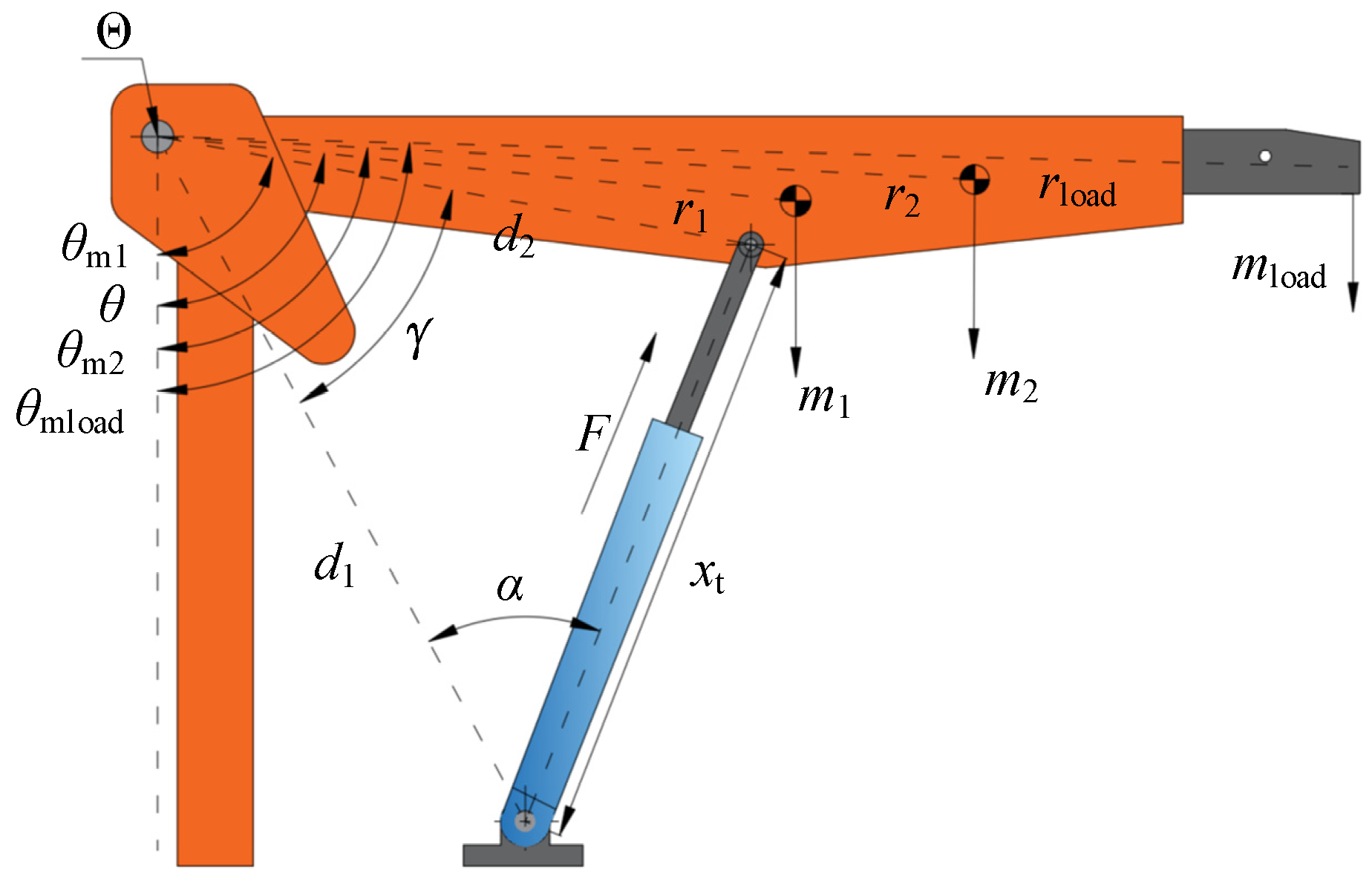
Figure 4.
Simulation model of the crane with DDH.
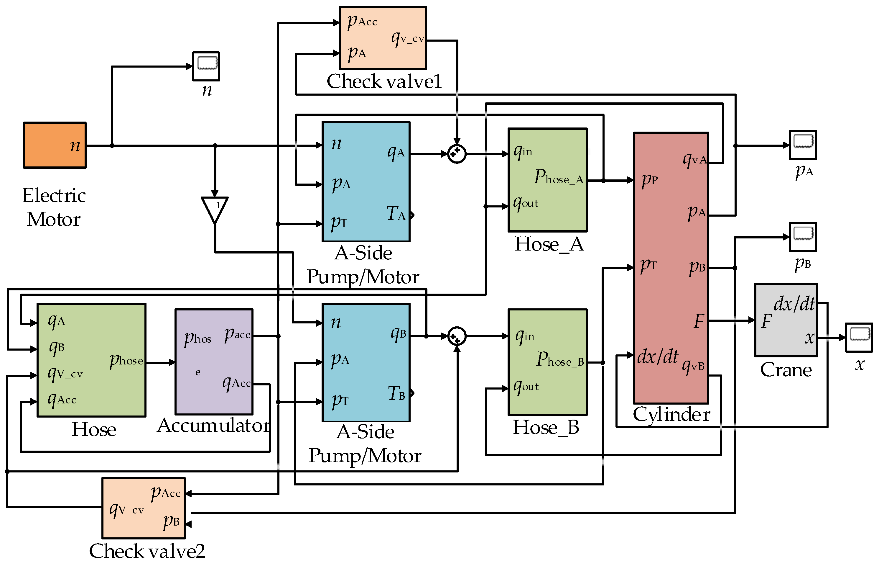
Figure 5.
Measured rotational speed of the electric motor.
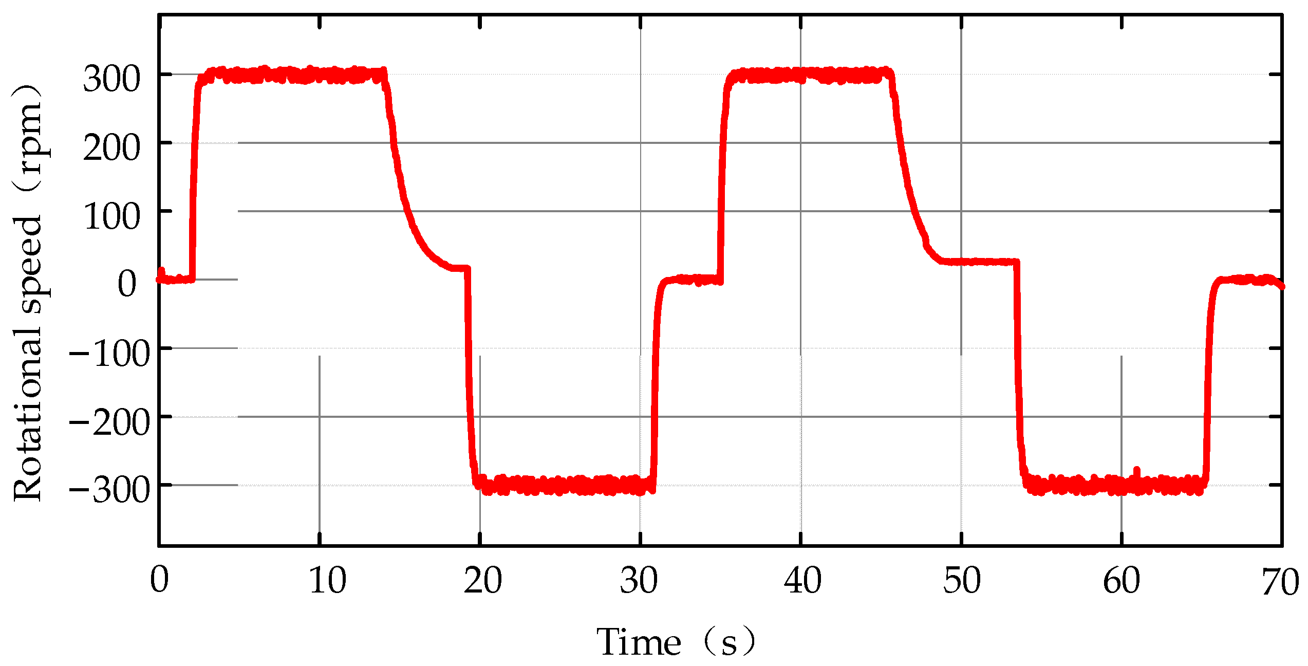
Figure 6.
Simulation and experimental cylinder displacement.

Figure 7.
Displacement error of the cylinder.

Figure 8.
Simulation and experimental pressure of the cylinder cap-side.
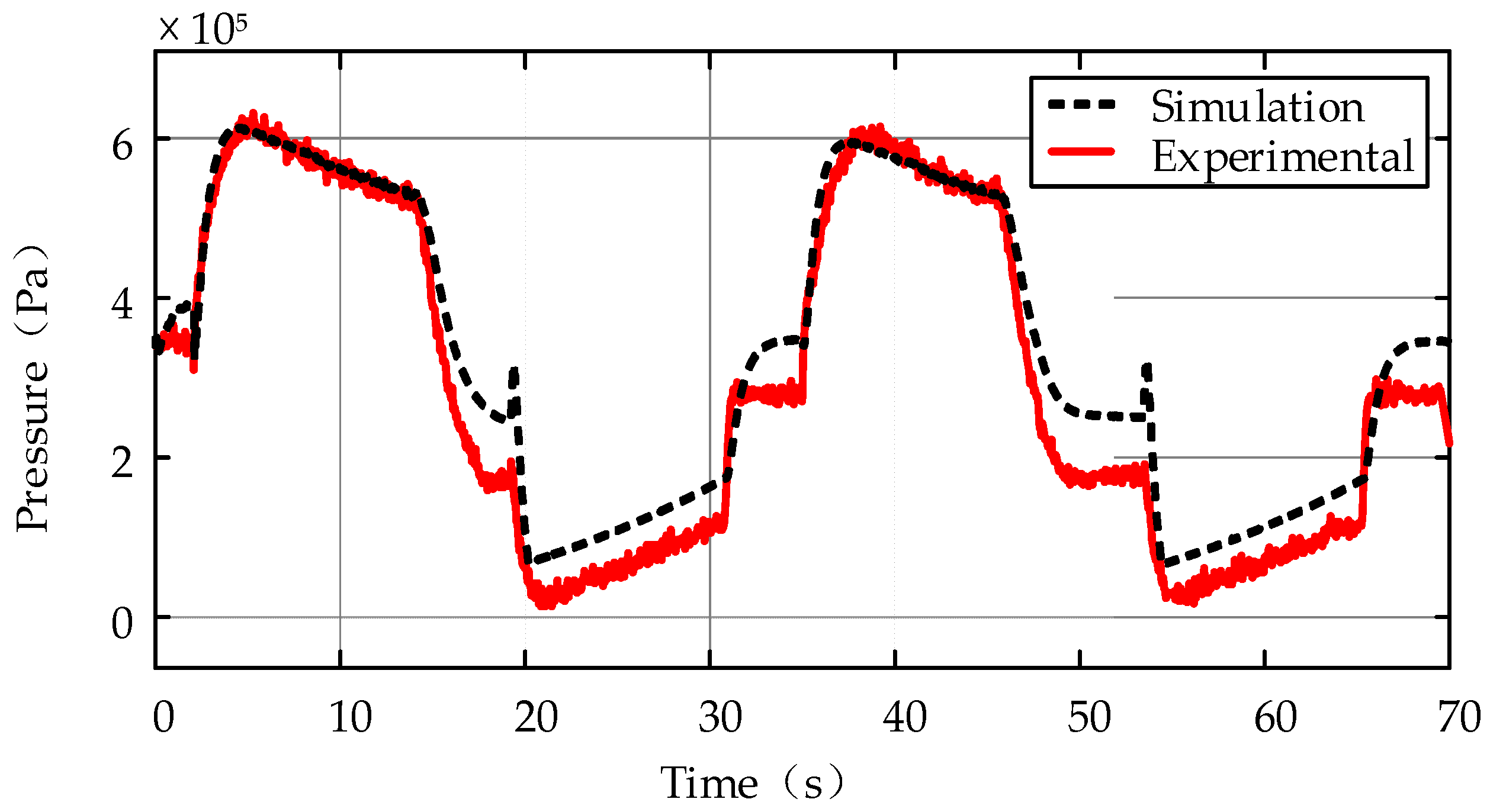
Figure 9.
Simulation and experimental pressure of the cylinder rod-side.

Figure 10.
Schematic diagram of position soft-sensing.

Figure 11.
The nonlinear relationship of the DDH.
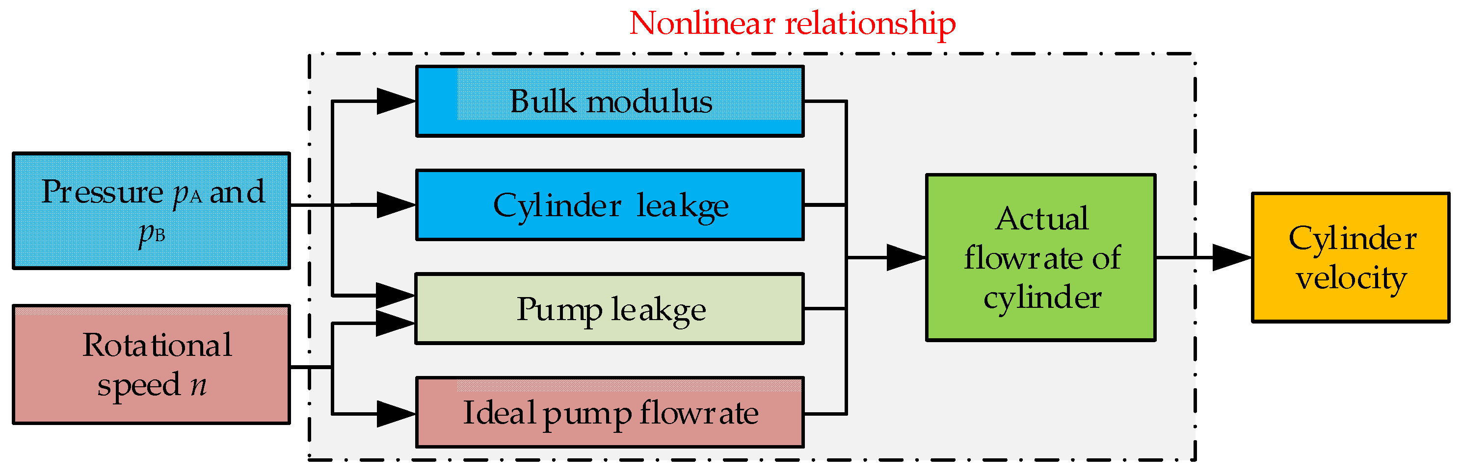
Figure 12.
Structure diagram of the BP neural network. (w1 and w2 represents the connection weights, b1 and b2 the thresholds).
Figure 12.
Structure diagram of the BP neural network. (w1 and w2 represents the connection weights, b1 and b2 the thresholds).
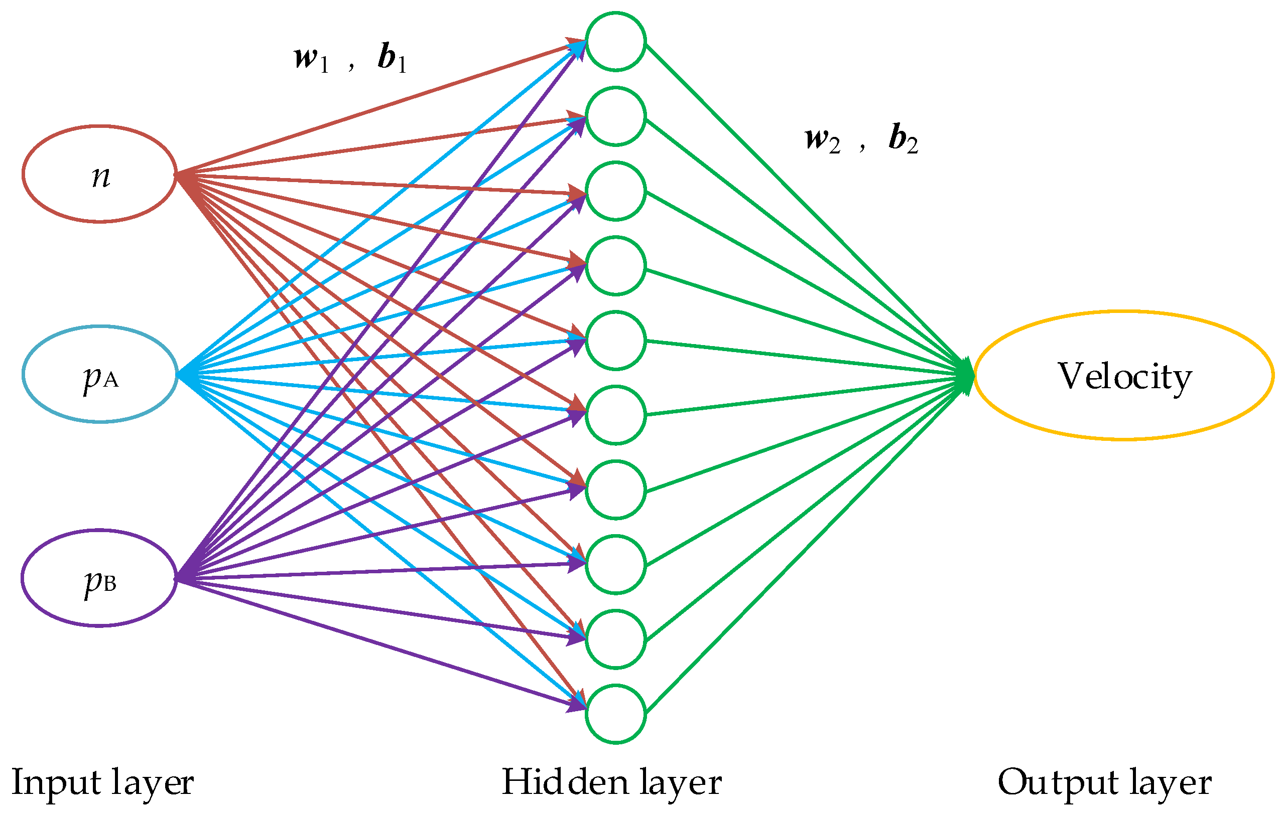
Figure 13.
Reference speed of the electric motor for the batch simulation.
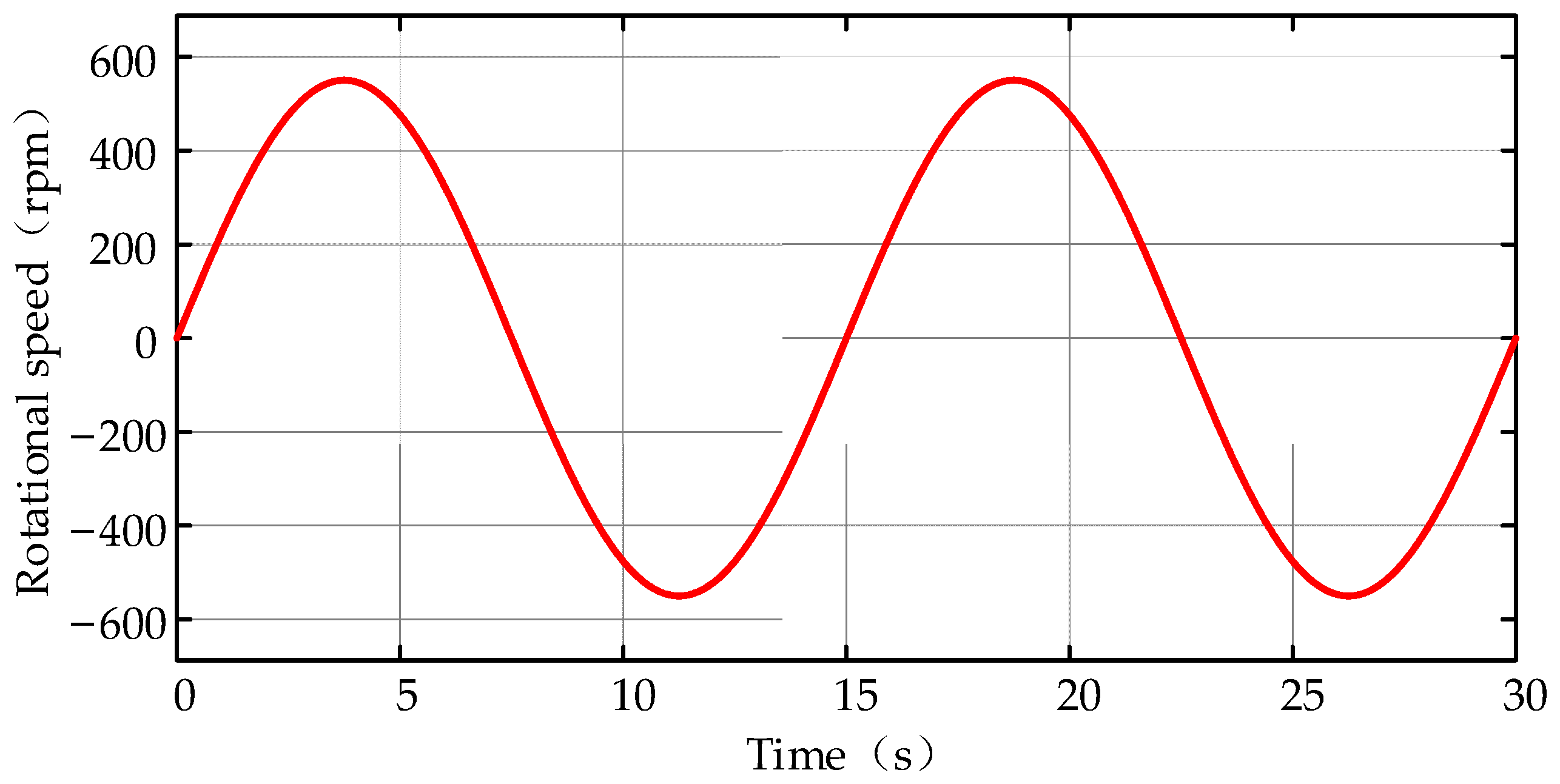
Figure 14.
pA with the sinusoidal reference signal f1(t) under a load of 0–250 kg.
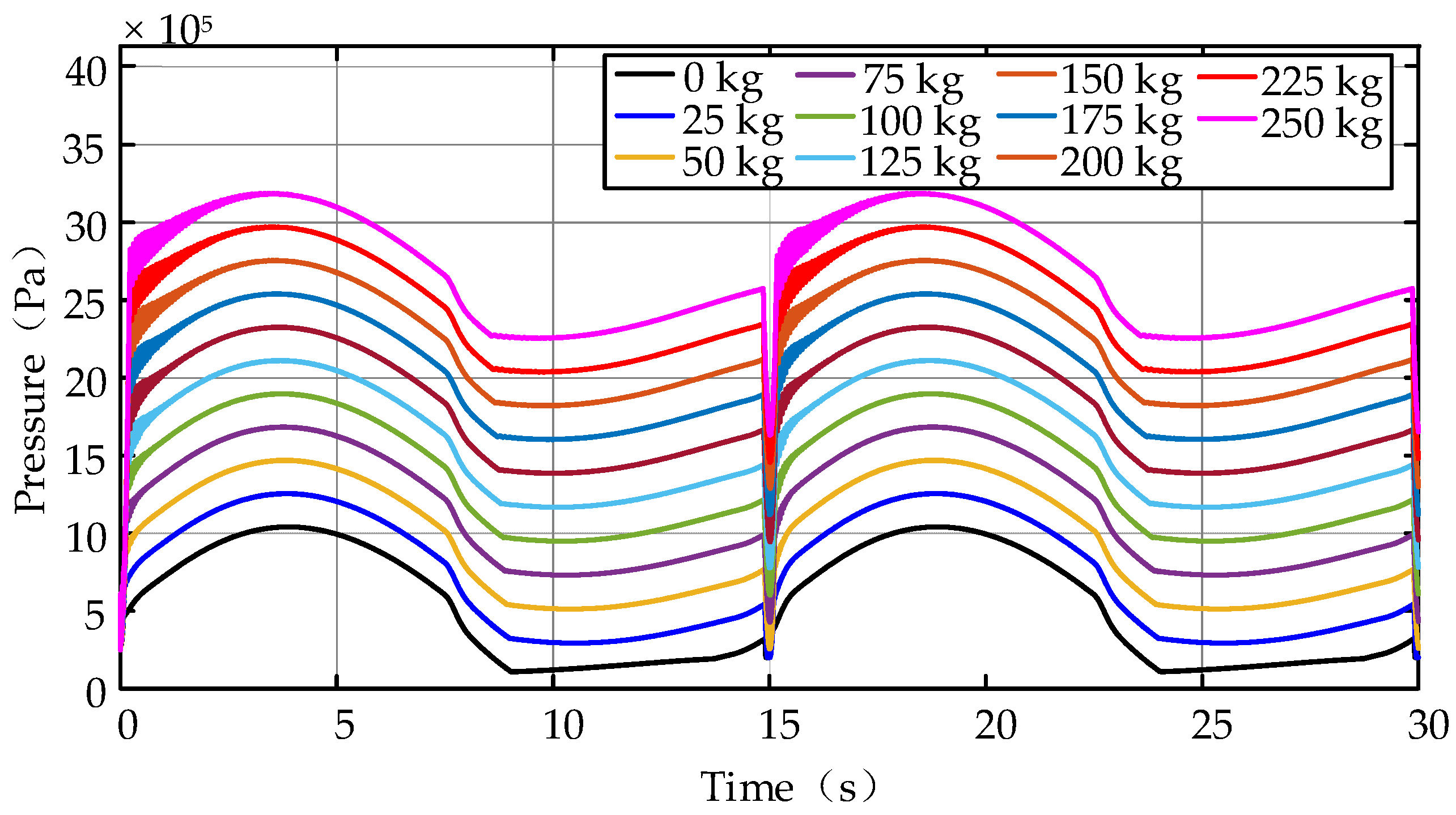
Figure 15.
pB with the sinusoidal reference signal f1(t) under a load of 0–250 kg.
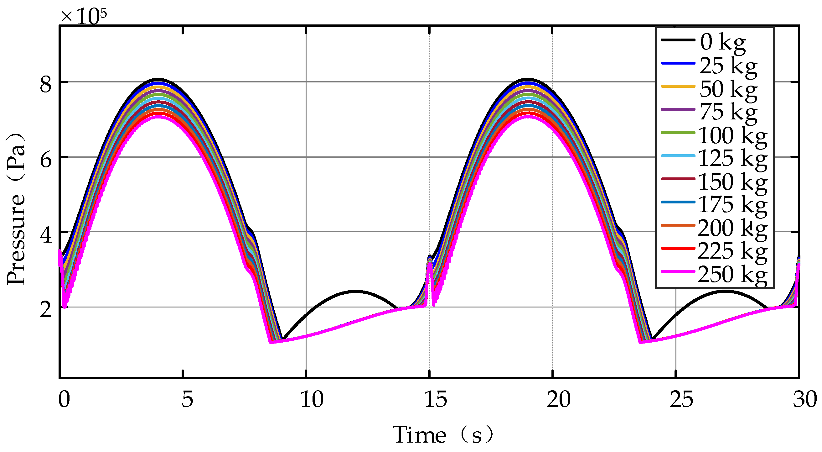
Figure 16.
Cylinder velocities of the sinusoidal reference signal f1(t) under a load of 0–250 kg.

Figure 17.
Training results with the testing set.

Figure 18.
Neural network training performance (plot–train–state), epoch 113, validation stop. (Note: the small circle position represents the mean square error at the number of training terminations (i.e., algebra)).
Figure 18.
Neural network training performance (plot–train–state), epoch 113, validation stop. (Note: the small circle position represents the mean square error at the number of training terminations (i.e., algebra)).
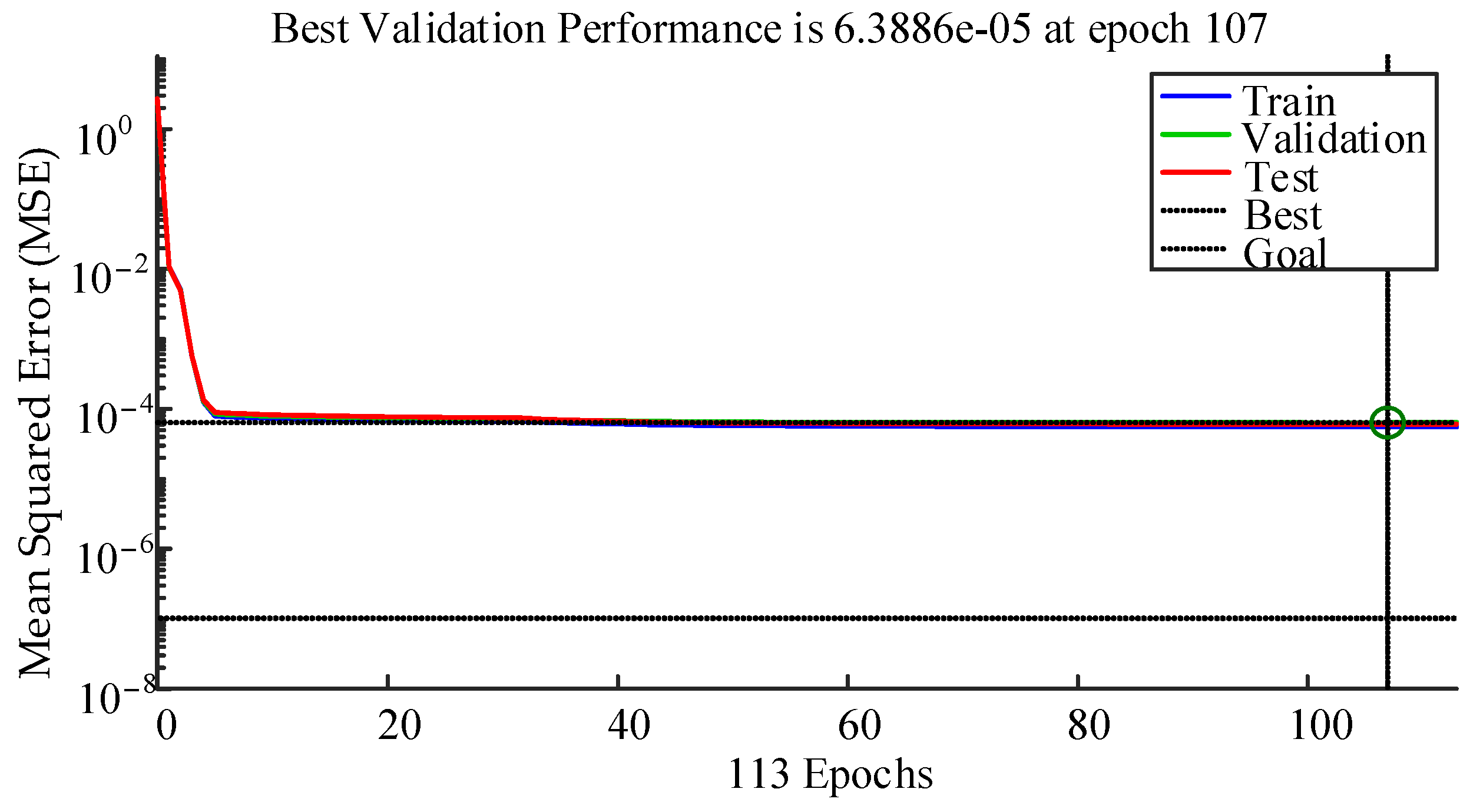
Figure 19.
Neural network training state (plot–train–state), epoch 113, validation stop.
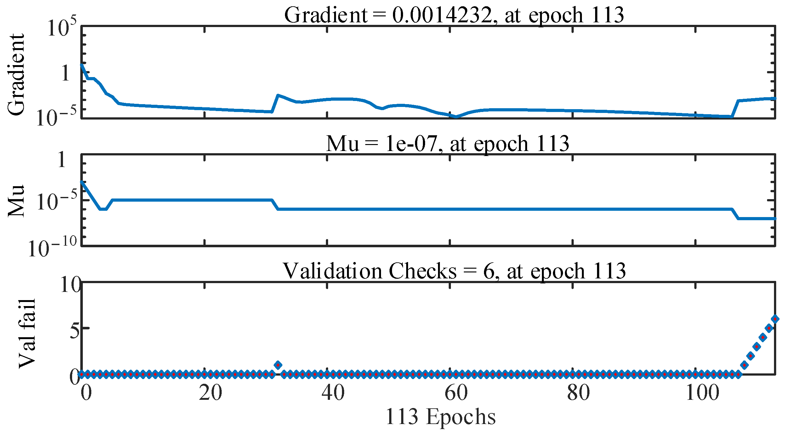
Figure 20.
Neural network training regression (plot–train–state), epoch 113, validation stop.
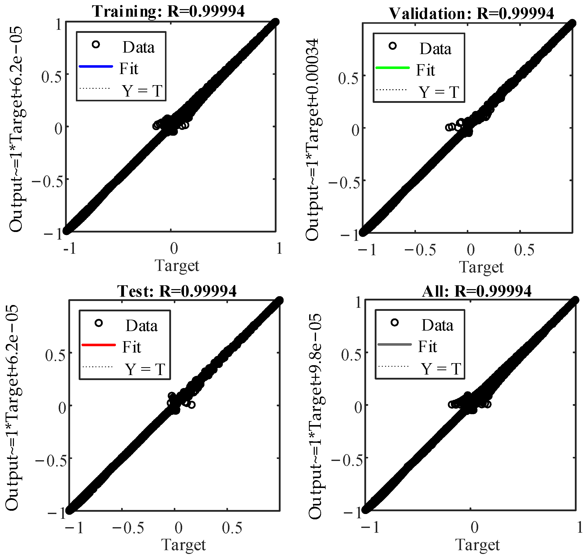
Figure 21.
Soft-sensing and experimental displacement.
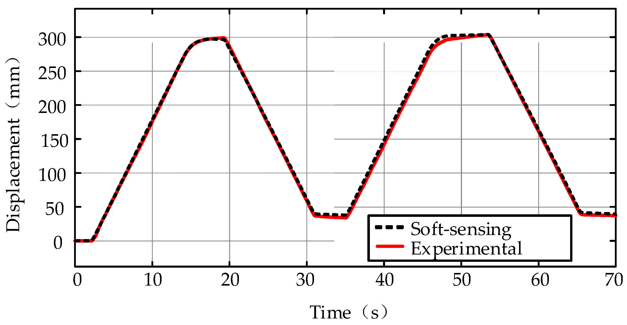
Figure 22.
Displacement error of the soft-sensing and experimental.

Figure 23.
Reference motor speed: the sinusoidal cycle.
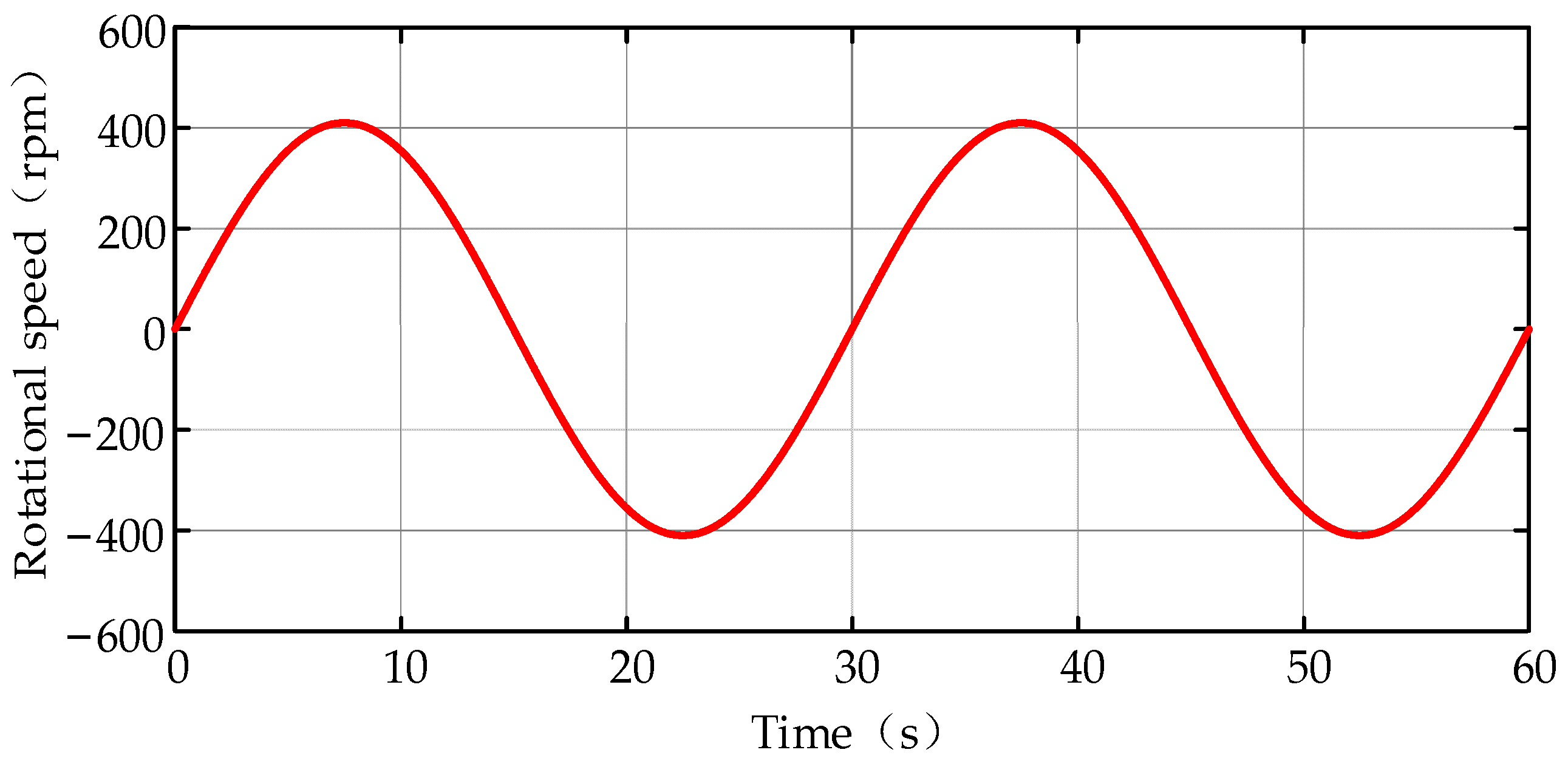
Figure 24.
Comparison of soft-sensing positions and simulated positions under three loads.

Figure 25.
Soft-sensing errors under three loads.
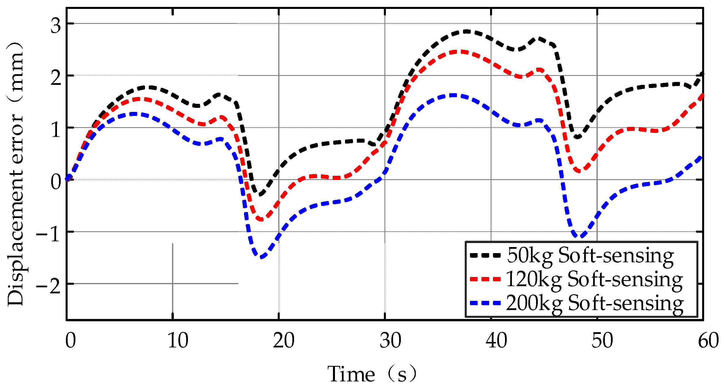
Figure 26.
Reference motor speed: a typical cycle.
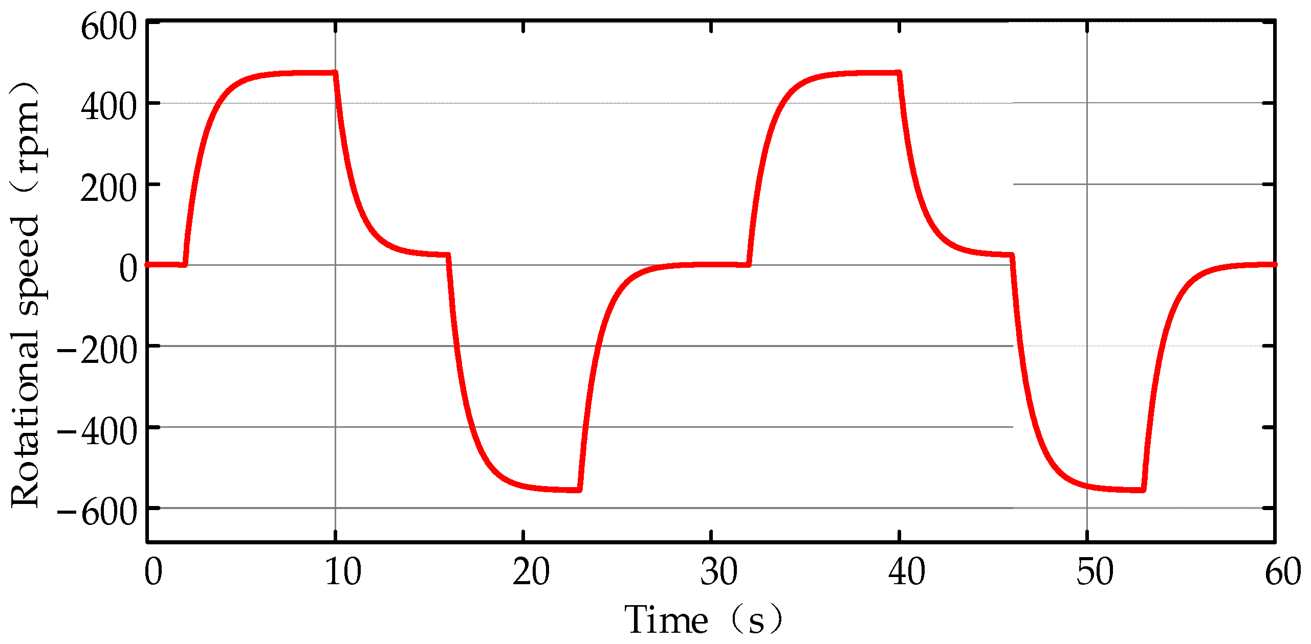
Figure 27.
Comparison of soft-sensing and simulated positions under three loads.
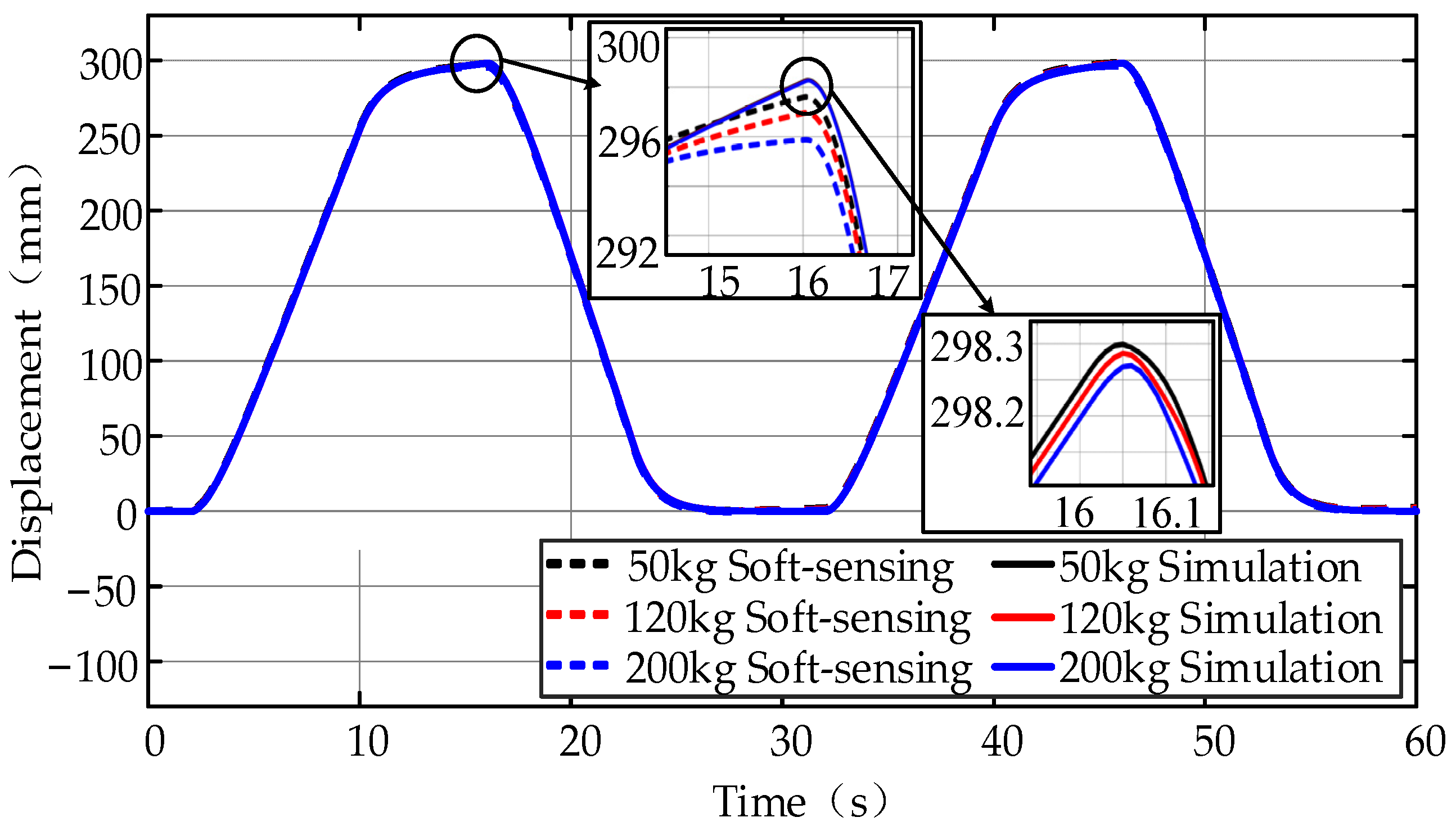
Figure 28.
Soft-sensing errors under three loads.
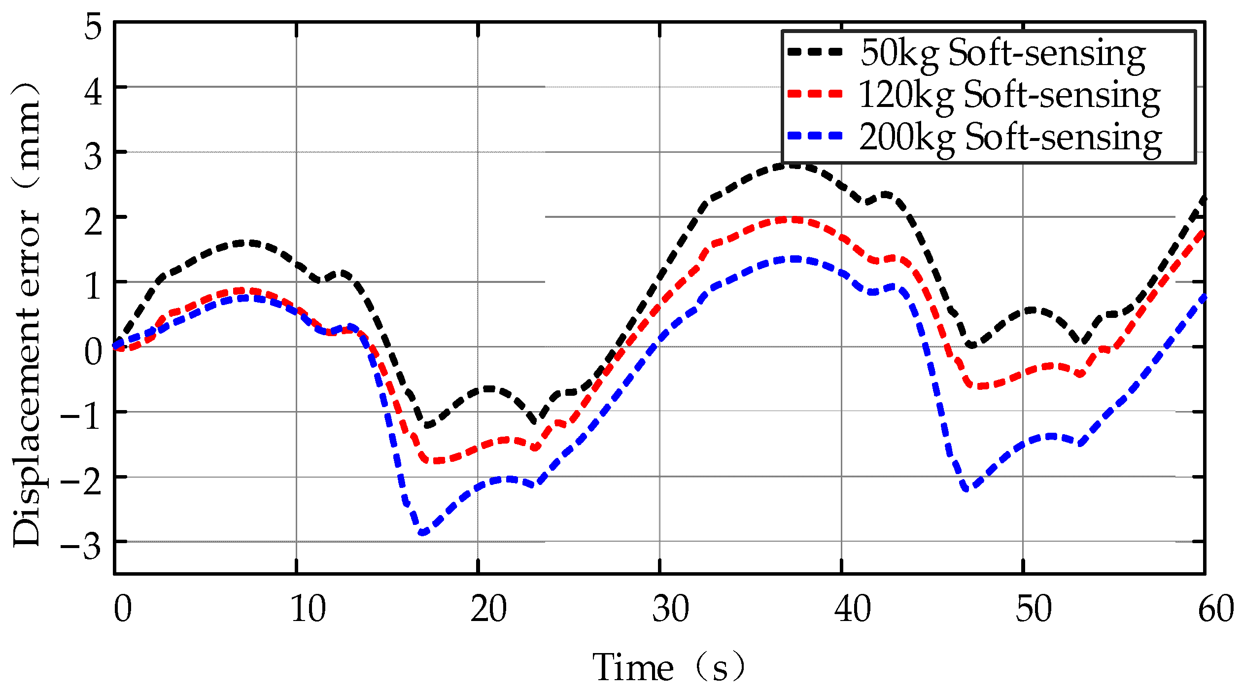
Figure 29.
Soft-sensing errors with a middle reference point under the sinusoidal cycle.

Figure 30.
Soft-sensing errors with a middle reference point under a typical cycle.
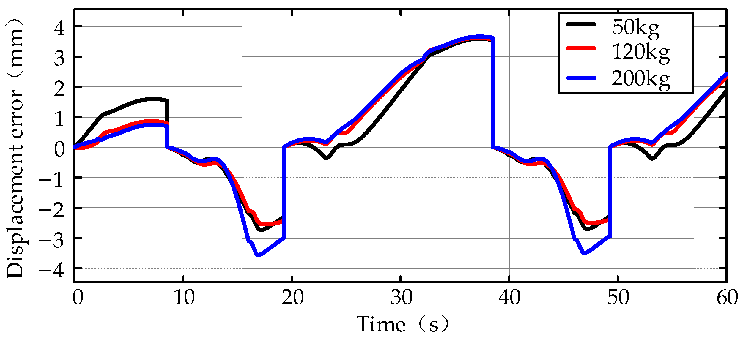
Figure 31.
Multi-cycle sinusoidal reference signal.
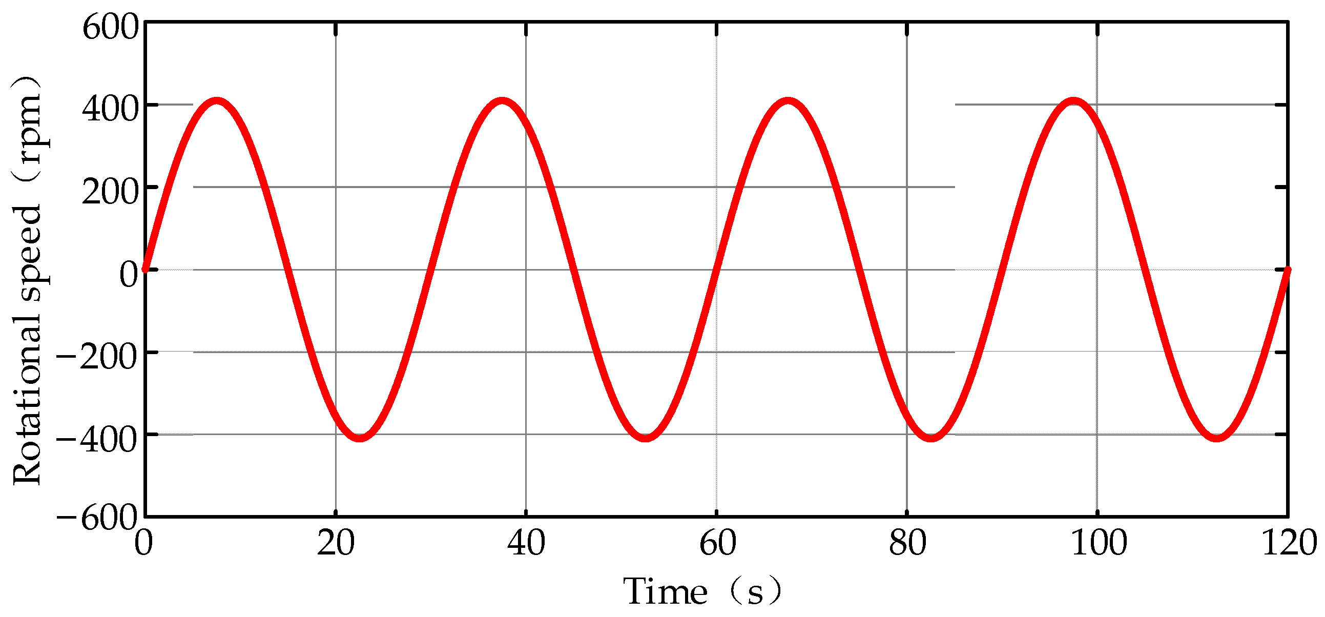
Figure 32.
Position comparison of soft-sensing with or without correction and simulation.
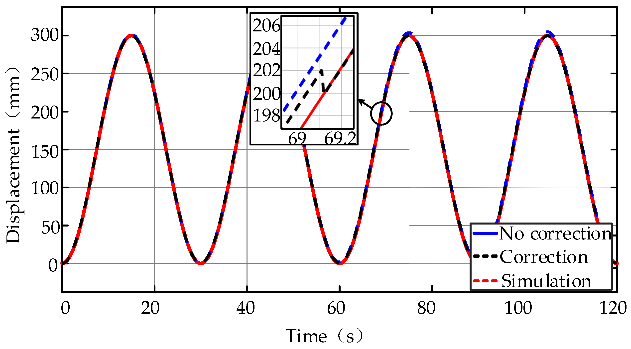
Figure 33.
Soft-sensing error with or without correction.


Table 1.
Parameters of the main components of the DDH.
| NO. | Component | Parameters | Value | Description |
|---|---|---|---|---|
| 1 | Synchronous Motor | Rated Torque [N·m] Rated Speed [rpm] | 4.5 2500 | Rexroth IndraDyn T Synchronous Torque Motor |
| 2 | A-Side Pump/Motor | Volumetric Displacement [cm3/rev] | 13.03 | Rexroth External Gear motor AZMF Series |
| 3 | B-Side Pump/Motor | 9.35 | ||
| 4 | Hydraulic Accumulator | Rated Volume [L] | 0.7 | Rexroth Diaphragm Type |
| 5 | Cylinder | Dimensions [mm] Rated Pressure [MPa] | 60/30 × 40,019.0 | MIRO C-10 |
| 6 | Pressure Sensor | Pressure Range [MPa] Accuracy | 0–20 0.25% FS | GEMS 3100 Series |
| 7 | Position Sensor | Resolution [mm] | 0.1 | SIKO SGI Wire Incremental Encoder |
Table 2.
Mechanical structure parameters of the crane [25].
Table 2.
Mechanical structure parameters of the crane [25].
| Parameters | Value | Unit |
|---|---|---|
| d1 | 0.983 | m |
| d2 | 0.637 | m |
| m1 | 25.11 | kg |
| m2 | 21.40 | kg |
| mload | 50 | kg |
| r1 | 0.693 | m |
| r2 | 0.977 | m |
| rload | 1.674 | m |
| γ0 | 80 | degree |
| θm10 | 0.1169 | rad |
| θm20 | 0.1572 | rad |
| θmload | 0.1775 | rad |
Publisher’s Note: MDPI stays neutral with regard to jurisdictional claims in published maps and institutional affiliations. |
© 2021 by the authors. Licensee MDPI, Basel, Switzerland. This article is an open access article distributed under the terms and conditions of the Creative Commons Attribution (CC BY) license (https://creativecommons.org/licenses/by/4.0/).
Share and Cite
MDPI and ACS Style
Zhang, S.; Chen, T.; Minav, T.; Cao, X.; Wu, A.; Liu, Y.; Zhang, X. Position Soft-Sensing of Direct-Driven Hydraulic System Based on Back Propagation Neural Network. Actuators 2021, 10, 322. https://doi.org/10.3390/act10120322
AMA Style
Zhang S, Chen T, Minav T, Cao X, Wu A, Liu Y, Zhang X. Position Soft-Sensing of Direct-Driven Hydraulic System Based on Back Propagation Neural Network. Actuators. 2021; 10(12):322. https://doi.org/10.3390/act10120322
Chicago/Turabian StyleZhang, Shuzhong, Tianyi Chen, Tatiana Minav, Xuepeng Cao, Angeng Wu, Yi Liu, and Xuefeng Zhang. 2021. "Position Soft-Sensing of Direct-Driven Hydraulic System Based on Back Propagation Neural Network" Actuators 10, no. 12: 322. https://doi.org/10.3390/act10120322
Note that from the first issue of 2016, this journal uses article numbers instead of page numbers. See further details here.