On the Optimization of a Multimodal Electromagnetic Vibration Energy Harvester Using Mode Localization and Nonlinear Dynamics


1
Department of Applied Mechanics, FEMTO-ST Institute, CNRS/UFC/ENSMM/ UTBM, University Bourgogne Franche-Comté, 25000 Besançon, France
2
Research Laboratory of Mechanics Modeling and Production, National Engineering School of Sfax, University Sfax, Sfax 3038, Tunisia
*
Author to whom correspondence should be addressed.
Actuators 2021, 10(2), 25; https://doi.org/10.3390/act10020025
Submission received: 23 December 2020
/
Revised: 16 January 2021
/
Accepted: 26 January 2021
/
Published: 30 January 2021
Abstract
:In this paper we study a generic model of a nonlinear quasiperiodic vibration energy harvester (VEH) based on electromagnetic transduction. The proposed device consists of multiple moving magnets guided by elastic beams and coupled by repulsive magnetic forces. A system of two degrees-of-freedom (DOFs) with tunable nonlinearity and mode localization is experimentally validated. The validated 2-DOFs harvester is optimized using a multiobjective optimization procedure to improve its harvested power and frequency bandwidth. An efficient criterion using the modal kinetic energy of the finite element model is proposed to quantify the energy localized in the structure perturbed zones. Afterward, this concept has been generalized to a 5-DOFs VEH with two perturbed DOFs oscillators and the optimal performances are derived using a multiobjective optimization. This proposed model enables a significant increase in the harvested power and frequency bandwidth by and , respectively, compared to that of the 2-DOFs device. Moreover, it has been shown that harvesting energy from two perturbed magnets among five provides almost the same amount of harvested energy and enhances the frequency bandwidth by compared to those of the periodic system. Consequently, the harvester can be improved by reducing the transduction circuits number and the manufacturing cost.
1. Introduction
Over the last years, wearable devices and embedded systems have been increasingly introduced in diverse applications. Most portable devices depend on batteries as the main energy source. However, they have a limited lifespan even with continuous progress in producing high-energy-density batteries [1]. Therefore, collecting energy from the environment ambient sources and converting it into usable electricity is challenging [2,3,4]. Harvesting energy techniques from different sources have received much attention [5]. Energy harvesting from vibrations, as one of the most studied methods [6,7], has a major challenge in converting vibration energy into electrical energy. Multiple studies proposed different designs of vibration energy harvesters [8,9] used in wireless sensors which are considered as self powered systems. The energy storage is possible through different conversion technologies namely electrostriction [10], magnetostriction [11], piezoelectricity [12,13] and electromagnetism [14].
In spite of considerable progress, major limitations need to be overcome in the field of vibration energy harvesting [15]. For instance, most vibration energy harvesting devices effectively operate in a narrow bandwidth near to their resonance frequency. Consequently, their application is limited to specific domains and they can not be used where energy prevails over a larger bandwidth. To overcome this problem, several approaches concerning the vibration energy harvesters have been proposed and have proved reliable results. Among them, one can mention the introduction of the nonlinearity [16,17], the adoption of multimodal configurations [18,19], the combination of two or more of the techniques mentioned, etc.
Adopting a multimodal approach helps to cover a certain range of frequency to achieve a broader bandwidth. For that reason, multiple researchers have developed energy harvesters with multiple DOFs [20,21,22,23]. Benefits of the multimodal method with the functionalization of the energy localization phenomenon have been, recently, investigated [24,25]. The energy localization phenomenon, first developed by Anderson [26], is exploited to increase the amplitude of vibration and also to enhance the harvested power. When an irregularity is introduced in the periodic system, the energy will be localized in regions near to this imperfection instead of being propagated in an equal manner to all system’s regions [27,28,29]. Although the fact that multimodal techniques enable a wider bandwidth for energy harvesters, their implementation leads to severe technological constraints due to the interface required to the electrical circuits and the high costs of the latter. Consequently, the nonlinearity is introduced to address this limitation and also to overcome the restriction of the conventional linear VEHs having a narrow operating bandwidth [30,31]. The nonlinearity of the device is presented in many works in different ways. The researches were oriented to change the natural frequency of a system by controlling its geometrical characteristics [32,33], by introducing external forces [34], via the interaction of the oscillator with the magnetic field [35,36,37,38] or by imposing high displacements [39], etc. These methods proved that the introduction of nonlinear dynamics increases significantly the frequency bandwidth of the devices. In recent works published by the authors of this paper, the benefits of the combination of the nonlinearity and the energy localization phenomenon have been investigated in a two degrees-of-freedom (2-DOFs) system [40,41]. It has been proved that the introduction of nonlinear dynamics enhances the frequency bandwidth and offers a higher energy localization robustness compared to the linear systems. Moreover, it has been confirmed that the functionnalization of the energy localization allows enhancing the harvested power. Furthermore, to produce a high-efficiency output harvester, the optimization of the vibration energy harvesters has gained a lot of interest. For instance, many studies have been conducted to optimize the output power and the structure aspects of the harvesters [42,43]. Several optimization approaches have been used such as the Non-Dominated Sorting Genetic Algorithm II (NSGA-II) [44], the new optimization methodology based on Artificial Intelligence (AI) [45], etc.
In this work, a multimodal electromagnetic vibration energy harvester with tuning nonlinear dynamics and energy localization is studied. The results of [40,41], allow the experimental validation of the 2-DOFs model. The validated 2-DOFs system is optimized using a multiobjective optimization procedure to improve the VEH harvested power and frequency bandwidth. An efficient criterion using the modal kinetic energy of the finite element model is proposed to quantify the energy localized in the perturbed zones of the quasiperiodic structure. This concept is then generalized to a 5-DOFs VEH where two DOFs oscillators among five are perturbed. A complete optimization procedure using the NSGA-II has been conducted to search for the optimal position of the introduced perturbations. Subsequently, a multiobjective optimization with tuning nonlinearity and mode localization is performed to enhance the harvesting output performance. The obtained results prove that the proposed method provides an efficient tool to design a large harvester with promising performances in terms of harvested power and frequency bandwidth compared to the current state of the art.
2. Mechanical Model
2.1. Proposed Design
Figure 1 illustrates the generic proposed vibration energy harvester. It consists of N neodymium magnets guided by elastic steel beams and weakly coupled by repulsive magnetic forces. These moving magnets are placed between top and bottom fixed magnets. The coupling is tuned by varying the gap between magnets thanks to the changement of position of the beams inserted into threaded rods. Wire-wound copper coils are wrapped around the moving magnets. When the device is subjected to a harmonic base excitation where is the imposed acceleration amplitude, each moving magnet oscillates around its equilibrium position. Consequently, a current is induced in each coil according to Lorentz’ law. quantifies the displacement of the magnets. The two magnets at the ends of the array are considered to be fixed so that . The periodicity of the structure is broken by mistuning few magnet masses.
2.2. Equation of Motion
The fourth order partial differential equations of the continuum system are derived using the Hamilton principle as detailed in Appendix A. The following equation of motion is then obtained:
where stands for the transverse displacement of the nth beam . and . denote respectively the derivatives with the spatial variable and the time. L, , , I, E, , , , S and M are respectively the beam half-length, the magnet half-diameter, the steel density, the beam quadratic moment, the steel’s Young modulus, the mechanical damping, the electrical damping, the magnetic force, the beam section and the magnet mass.
For reasons of symmetry of the 1st mode, each beam is fixed at and guided at , so the associated boundary conditions are:
To transform the continuous multiphysics problem into a system of discrete ordinary differential equations in the time domain, the Galerkin modal decomposition is used and is detailed in Appendix B. Consequently, dividing Equation (A11) of Appendix B by the equivalent mass , the equation of motion of the nth DOF is written in terms of generalized coordinates as follows:
where is the equivalent viscous damping, is the coupling factor, is the mechanical nonlinear term while assuming that the magnetic nonlinear term is neglected compared to the mechanical nonlinear term , p stands for a mass ratio and is the eigenfrequency of the decoupled 1-DOF oscillator. and are defined in Equation (A6). , , , and are defined in Equation (A12).
The mass mistuning coefficient is introduced in Equation (3). Thus, the equation of motion of the nth magnet can be written as follows:
where
as we consider two additional fixed magnets at the ends of the array: .
2.3. Modal Localization Phenomenon
The energy localization phenomenon occurs under conditions of internal weak coupling in nearly periodic structures. In fact, when a small disorder is introduced, the symmetry of the periodic system is broken leading to energy confinement in the perturbed region. To illustrate the energy localization phenomenon, a multi-degree-of-freedom system consisting of an array of 10 weakly coupled beams considered to be perfectly periodic, shown in Figure 2, is proposed. A finite element method is, then, developed to study this system. The elastic beams are bi-clamped and the coupling between the beams is insured via spring connexions where their stiffnesses are fixed so that the coupling is weak . The assumption of the weak coupling leads to the creation of closed modes where all normal frequencies may be expressed with respect to the reference frequency as follows:
where , and is the coupling factor.
The Taylor expansion of gives the following approximate solution of all normal frequencies:
This assumption permits to create closed modes in order to study the energy localization phenomenon. The natural eigenfrequencies of the 10-beams system are reported in Table 1.
The first mode shapes and their sensitivity to the introduced mistuning are shown in Figure 2. The vibrations of the periodic system, observed in Figure 2a, are uniformly distributed. Then, the mistuning was introduced to the 10-beams structure by varying the density of three arbitrary beams among 10 by (the 3rd, 6th and 9th beams and the 2nd, 5th and 8th beams counting from the bottom in Figure 2b,c, respectively). The perturbed beams have notably more displacements than the others and this is modeled in terms of kinetic energy confined in the mistuned regions shown in Figure 2b,c. Comparing the results of the configurations illustrated in Figure 2c,d where the irregularities are placed in the same positions but with different amount, the energy localization is more accentuated and kinetic energies of the perturbed beams are significantly higher then the others in the case of the density mistuning by .
Consequently, to quantify the mode localization and predict its occurrence, a criterion is proposed. The ratio between the modal kinetic energies of the concerned local DOFs and the global structure will be calculated, for each mode, as follows:
where is the mass matrix of the area made up of n elements, is the eigenvector restriction of this area, X and M are respectively the eigenvector of the considered mode and the mass matrix of the full model.
According to that, applied to the 1st and 2nd DOFs in periodic (Figure 2a) and quasiperiodic (Figure 2b) configurations are respectively of and . It can be concluded through this example that the localized energy in 2-DOFs of the quasiperiodic system is equal to the energy of 5-DOFs in the periodic system.
In the particular case of discrete system with N DOFs, this criterion can be written as follows for the DOF n:
where and are respectively the mass and the displacement of the considered DOF n.
3. Multiobjective Optimization of the Validated Two-Coupled-Beams Harvester
3.1. Numerical-Experimental Confrontation
The concept combining the benefits of geometric nonlinearities and energy localization is proposed to enhance the performances of a periodic weakly coupled electromagnetic VEH device. These effects on the frequency bandwidth as well as on the harvested power have been investigated in [40]. Following this study, it has been concluded that the energy can be harvested from one perturbed magnet instead of two and only one electric circuit can be used while the maximum harvested energies are comparable and the bandwidth is enhanced compared to the results of the periodic structure. Subsequent work included the manufacturing and experimental characterization of the proposed device under harmonic excitations [41]. The nonlinearity level has been tuned by varying the critical resistances and the energy localization has been controlled by the mass mistuning. Through this study, it has been confirmed that the experimental tuning of these phenomena allows the enhancement of the VEH performance in terms of frequency bandwidth and harvested energy and the compromise solution that maximizes simultaneously the main objectives has been experimentally determined. Moreover, it has been proved that the nonlinear dynamics offer a higher robust energy localization compared to the linear system. Despite the significant improvement in the performances of the 2-DOFs device, a complete multiobjective optimization needs to be performed for further enhancement of the generic harvester.
First, a system of 2-DOFs is studied. The power is harvested only from the oscillations of the 2nd perturbed magnet. Therefore, the harvested power is expressed as follows:
where , , and stand respectively for the maximum amplitude of the frequency response of the second perturbed DOF oscillator, the transduction circuit load resistance, the coil internal resistance and the electromagnetic coefficient.
The system of equations of a 2-DOFs model where the second DOF oscillator is perturbed, is generated according to Equation (4). It is solved using ode45 method. The amplitudes and the harvested power are calculated. All the numerical simulations are performed with a basis acceleration equal to g, a gap mm and a coupling coefficient . The kinetic energies based on the criterion defined in Equation (8) while varying the value of the mass mistuning is plotted in Figure 3a. The largest difference between the kinetic energies is obtained when as observed in this Figure. Based on the test bench described in [41], several experiments have been performed in order to validate the numerical results. To do that, the magnet masses are perturbed by adding small masses to the magnets. In order to accurately measure voltage peak, up and down frequency sweeps for all the following experimental tests, which allow the capture of the bifurcation points of the nonlinear frequency response, have been done. The amplitudes and masses of the 2-DOFs oscillators are being experimentally obtained while varying the mass mistuning coefficents, the corresponding kinetic energies are calculated through Equation (8) and plotted in Figure 3a. As shown, the optimal mass mistuning is and is in good agreement with that of the numerical simulations.
The harvested power with load resistances is numerically calculated for the optimal mistuning value based on Equation (9). While varying the load resistances during the experimental tests, the current flowing in each load resistance provides an electric power calculated as where V is the voltage generated by the coil. As shown in Figure 3b, the optimal load resistance which gives the maximum power is for both numerical and experimental results.
A quantitative comparison between theoretical and numerical results is achieved. In fact, the optimal mass mistuning and the optimal load resistance are in good agreement with the experimental results . The model predicts the values of the maximum harvested powers with error of .
3.2. Optimization of the Validated Model
During simulations, it was possible to find a maximum power but a minimum bandwidth. While the performance of the harvester in terms of harvested power and frequency bandwidth has been improved by tuning nonlinearity and mode localization, a multiobjective optimization needs to be done to further enhance the harvester and obtain its optimal parameters. This approach has been applied in many fields where optimal decisions need to be taken in the presence of trade-offs between several objectives.
In the following, this procedure is introduced using an extension of the Genetic Algorithm (GA) [46] for multiple objectives which is the Non-dominated Sorting Genetic Algorithm II (NSGA-II) [47]. The latter is related to evolutionary multiobjective algorithm that aims at improving the adaptive fit of a population to a Pareto front composed of a set of compromise solutions between the objectives. The formulation of the problem is defined in Table 2.
Where stands for the critical load resistance used to tune the nonlinearity level. It has been obtained from experiments performed in [41] and it is equal to . The load resistances used in the following optimization procedures should be higher than to guarantee a nonlinear behavior of the device.
The simulations performed generate the frequency responses of all the candidate solutions using the ode45 function of MATLAB. While assuming that the bifurcation point of the nonlinear response curves coincides with the maximum value of the frequency response, the bandwidth and the average harvested power are calculated.
After running the multiobjective algorithm convenient to this problem, the following Pareto front, illustrated in Figure 4, is generated.
The compromise solution that suits for the present problem is the one which maximizes simultaneously the two objective functions. Therefore, the selected Pareto solution and its corresponding parameters are defined in Table 3.
The corresponding optimal parameters , and are reproduced in the experimental tests to compare the numerical results to the experimental ones. The measured performances are illustrated in Figure 5.
The error between numerical and experimental results in terms of maximal harvested energy and maximal frequency bandwidth are respectively and . Thus, we can consider that the optimized model is in good agreement with the experimental results.
4. Optimization of a Multiple-Degree-of-Freedom: Five-Coupled-Beams
While a proof-of-concept of the 2-DOFs structure was designed, modeled, fabricated and characterized, demonstrating improved power and bandwidth performance, the model is generalized to a quasi-periodic 5-DOFs and its analytical solution is derived.
4.1. Optimal Position of the Introduced Mistuning
The governing equations of the generalized periodic 5-DOFs system is written as follows:
Based on the characterization of the previous configuration and the benefits of the combined techniques, two moving magnets’ masses are mistuned among the 5-DOFs. Each perturbed magnet mass will have its own mass mistuning coefficient and its own corresponding load resistance. As a choice, we set the same gap between the magnets. The possible combinations of the positions of the two mistuned DOF oscillators are: (a,b), (a,c), (a,d), (a,e), (b,c), (b,d) and (b,e) where for example stands for the DOF as illustrated in Equation (10). The decision of the position of the two DOFs to be perturbed will be made according to the case that provides the maximum energy harvested as formulated in Table 4.
To do that, a continuous optimization procedure involving discrete variables is used [48]. The set of discrete variables contains and which stand for the mistuning coefficients of the two perturbed oscillators. For these two values, the multiple possible combinations are treated. A continuous optimization algorithm, implemented in MATLAB, is called according to each combination of discrete variables. During the continuous optimization, those discrete variables denote the position and the value of the mistuning simultaneously. For that, they are modeled as a first step as discrete and then as continuous. In the case of two successive perturbed magnets, the combination is eliminated and not treated. This choice is made in order to have distributed perturbations over the network so that the energy localization is more efficient. During the conducted simulations, this system of equations is solved by the ode45 MATLAB solver. The optimization returns the position of the mass mistuning and the maximum harvested energy of the best configuration. Results indicate that the 5-DOFs system with mistuning of the 2nd and 4th DOFs, illustrated by the equivalent model in Figure 6, give the maximum harvested energy. Thus, the harvested power will be calculated through this expression in the following study: , where and are the harvested powers from the DOFs 2 and 4, respectively.
4.2. Multiobjective Optimization of the Five-Coupled-Beams Harvester
Aiming to simultaneously enhance the harvested energy and the frequency bandwidth of the 5-DOFs harvester with two mistuning, a multiobjective optimization is carried based on the genetic algorithm. The Pareto front of the kinetic energies of the mistuned magnets is plotted, as illustrated in Figure 7a, in order to visualize their trending variations. From one solution to another, the kinetic energies of the two perturbed dofs are conflicting. To improve the harvester performance, the kinetic energies of the perturbed DOFs should be maximized so their sum will be maximized in the following. In order to take advantage of the mistuned DOFs, both of them should vibrate in close proportions so they should have close energies. For that, during this procedure, the energy rates of the mistuned DOFs are controlled. This constraint is considered as the additional subjective preference information to choose the optimal solution enhancing the harvester. To do that, the energy localization rate between the 2nd and the 4th DOFs is defined as follows:
Then, the mutiobjective optimization problem is formulated in Table 5 as follows:
Pareto optimal solutions of the multiobjective optimization are depicted in Figure 7b and the two-dimensional projection is reported in Figure 8a. Among the multiple Pareto solutions, one will be chosen. The selection criterion is based on the solution that minimizes the difference between and . To do that, for each solution located inside the compromised interval, the corresponding difference between and is calculated and is illustrated in ’red’ in Figure 8a. Consequently, taking into consideration this additional subjective preference information, the compromised solution that maximizes the harvested power and the frequency bandwidth simultaneously is reported in Table 6.
Introducing these optimal values in the model, the frequency response in terms of harvested power is calculated and plotted in Figure 8b.
The simultaneous functionalization of the nonlinearity, the energy localization phenomenon and the multimodal configuration show an improvement up to of the harvested power and of the frequency bandwidth compared to the performances given by the 2-DOFs nonlinear system with perturbing only one DOF. The 5-DOFs periodic system is also studied in order to compare its performance to the one of the optimized quasiperiodic 5-DOFs system. In this case, the power is harvested from all the vibrating 5-DOFs oscillators . Following the same strategy, the Pareto front of the periodic system maximizing the harvested power is plotted in Figure 9. The optimal parameters that maximize simultaneously the harvested power and the frequency bandwidth for the periodic 5-DOFs system are , . The obtained results show that the proposed quasiperiodic model provides a larger bandwidth and comparable harvested power compared to the periodic one. In fact, the difference between the harvested powers in the two cases is of and the frequency bandwidth is higher by in the periodic system.
From these results, it can be concluded that the functionnalization of nonlinearity and mode localization in a multimodal device overcome the challenge of increasing the harvested energy and the frequency bandwidth. Moreover, the combination of these phenomena allows harvesting energy from only two DOFs oscillators instead of five while keeping comparable performance. The benefits of this property consist of reducing the cost of the electrical circuits to be implemented and the technological constraints of the structure.
To compare the optimized proposed harvester performance with the current state-of-the-art, the volume figure of merit () proposed by [49] has been chosen among diverse performance metrics in the literature for being the most general criterion. The volume figure of merit is the ratio of the harvester useful power output transferred to the load to the maximum theoretical power flowing into an equivalent device. This equivalent device has a cubic geometry with the same volume as the original harvester one but with a proof mass having the density of gold occupying this volume half, while the other half is destined to oscillation [49]. Hence, this figure of merit is calculated according to the following expression:
where is the imposed acceleration amplitude, is the resonant frequency, is the density of gold and is the harvester volume.
According to this figure of merit, the performance of the current work harvester and the ones of other harvesters are illustrated in Figure 10. As shown, the optimized proposed harvester provides competitive performance compared to the harvesters based on electromagnetic transduction as well as the ones based on hybrid piezoelectric-electromagnetic transduction.
5. Conclusions
In this work, a generic model of a nonlinear quasiperiodic VEH based on electromagnetic transduction has been studied. A 2-DOFs VEH with tunable nonlinearity and mode localization is experimentally validated. Then, the validated 2-DOFs structure is optimized using a multiobjective optimization procedure with respect of the harvested power and the frequency bandwidth. To quantify the energy localized in the perturbed zones of the quasiperiodic structure, an efficient criterion based on the modal kinetic energy of the finite element model is presented. Afterward, the concept is generalized to a 5-DOFs structure and the optimal performances are derived using a multiobjective optimization procedure. It has been proved that the optimal parameters that improve the quasiperiodic 5-DOFs device performance enable an enhancement up to and in terms of harvested power and frequency bandwidth, respectively, compared to the 2-DOFs harvester. Moreover, through the performance comparison between the quasiperiodic 5-DOFs system with well-chosen mistuning positions and the periodic one, it has been proved that the functionalization of the nonlinearity and the energy localization allows more efficient frequency bandwidth and comparable harvested powers. Hence, the proposed quasiperiodic harvester is improved by reducing the transduction circuits number and the manufacturing cost. In addition, it has been shown that the optimized harvester has competitive performance compared to the current state-of-the-art. Finally, despite the fact that the generic harvester performances are optimized, an efficient energy harvester for small-scale realistic applications is challenging. Future work will include the miniaturization and experimental validation of the device with more than 2-DOFs as well as the optimization of its performance while investigating the nonlinear energy localization phenomenon and its stability [58].
Author Contributions
Conceptualization, K.A.; Data curation, K.A.; Formal analysis, K.A., N.K., N.B. and M.H.; Funding acquisition, N.K., N.B. and M.H.; Investigation, K.A., N.K. and N.B.; Methodology, K.A., N.K. and N.B.; Project administration, N.K., N.B. and M.H.; Resources, N.K., N.B. and M.H.; Software, K.A.; Supervision, N.K., N.B. and M.H.; Validation, K.A.; Writing—original draft, K.A.; Writing—review & editing, K.A., N.K., N.B. and M.H. All authors have read and agreed to the published version of the manuscript.
Funding
This research was funded by the EUR EIPHI program (ANR 17-EURE-0002).
Institutional Review Board Statement
Not applicable.
Informed Consent Statement
Not applicable.
Data Availability Statement
The data presented in this study are available on request from the corresponding author.
Conflicts of Interest
The authors declare no conflict of interest.
Appendix A. Dynamic Equations of Motion of the Continuous Structure
Based on the problem formulation detailed in Mahmoudi et al. [35], the continuum multiphysics system, including the equation of motion of the present structure and the magnetic transduction equation, is developed.
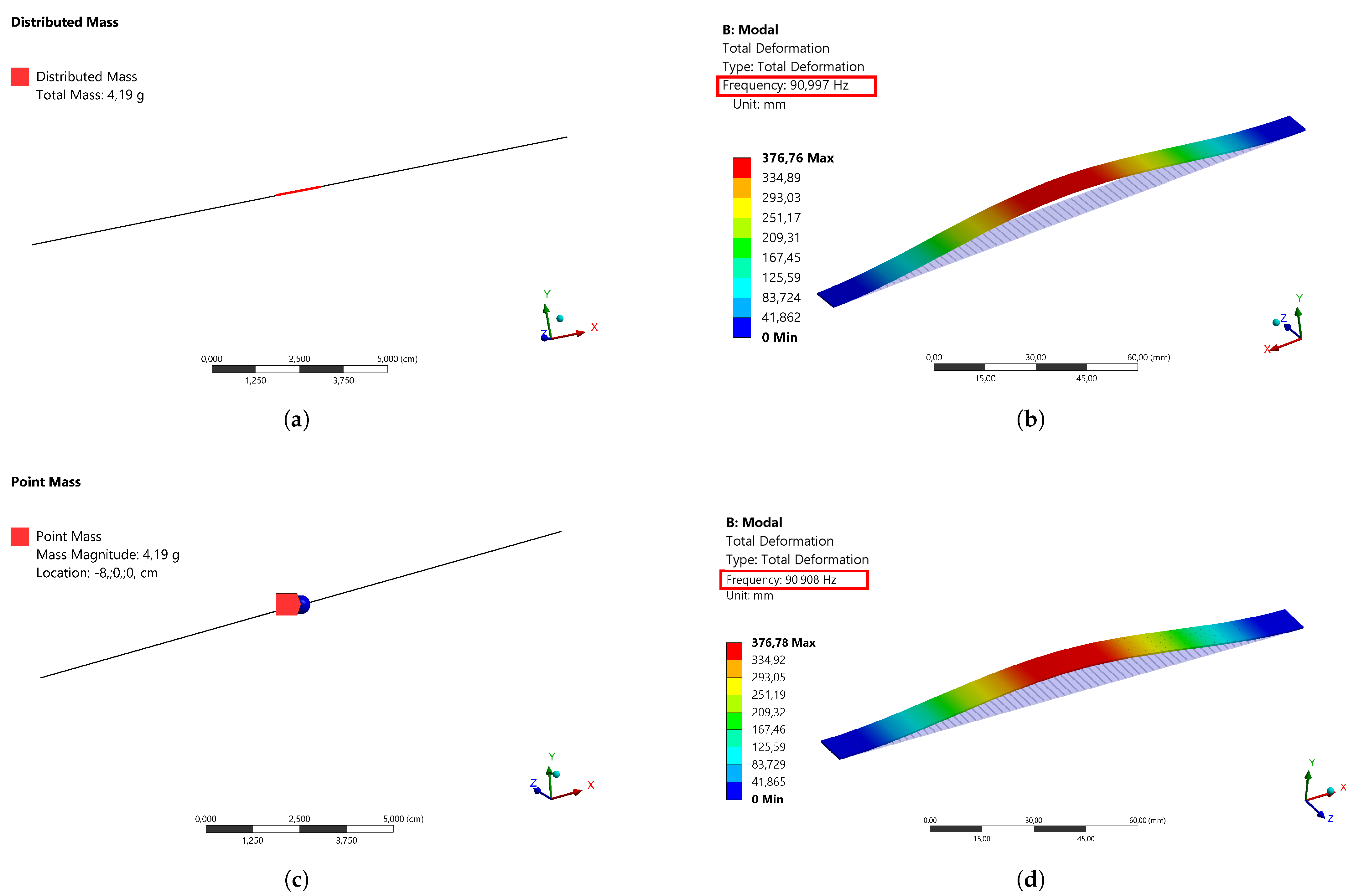
Appendix A.1. About the Hypothesis of the Localized Point Mass Magnet
To simplify the development of equations, the magnet mass has been considered to be a localized point mass for the mode of interest (1st). FEM simulations under ANSYS have been run to support this hypothesis. The illustrations of the distributed magnet mass and of the localized point mass are shown in Figure A1a,c, respectively. As reported in Figure A1b,d, the frequency of the beam and its mode shape are the same for the two configurations (Errors of , and , respectively in terms of displacement in the center, slope and frequency).
Appendix A.2. Equation of Motion
The fourth order partial differential equations of the continuum system are derived using the Hamilton principle. Applying the Hamilton’s variational approach to the dynamical system, we have the following equation:
where , , are respectively the works of the non-conservative forces, damping forces and exterior forces of the nth beam .
The magnets and the beams are identical and the distance d between the magnets is the same. When the magnets oscillate, magnetic and electromagnetic forces are created as a result of the variation of the magnetic field. The magnetic force depends on the magnetic intensities Q and the gap d is defined as follows:
where , is the coercive force, is the section of the magnetic pole and denotes the transverse displacements of the nth beam .
For , the following equation is obtained:
Figure A1.
Distributed magnet mass: (a) Illustration and (b) Frequency and mode shape of the beam. Point magnet mass: (c) Illustration and (d) Frequency and mode shape of the beam.
Figure A1.
Distributed magnet mass: (a) Illustration and (b) Frequency and mode shape of the beam. Point magnet mass: (c) Illustration and (d) Frequency and mode shape of the beam.
L, , I, E, , , , S and M are respectively the beam half-length, the steel density, the beam quadratic moment, the steel’s Young modulus, the mechanical damping, the electrical damping, the magnetic force, the beam section and the magnet mass.
For reasons of symmetry, the beam is fixed at and guided at , so the associated boundary conditions are:
and . denote respectively the derivatives with respect to the spatial and the time variable.
The magnetic transduction is provided by a coil wound around the separation distance between two consecutive magnets. The following mechanical-magnetic coupling equation is defined as follows:
where is the electromagnetic coefficient and and are respectively the load and the internal resistances.
To simplify the equations, the following dimensionless variables are introduced:
The coupled continuum multiphysics problem is then equivalent to the following equation:
Appendix B. Reduced Model by Galerkin Modal Decomposition
A reduced model is generated by Galerkin modal decomposition, transforming the continuous multiphysics problem into a system of discrete ordinary differential equations in the time domain. In order to solve the previous system, the displacements are projected on a single mode basis. The displacement of each DOF oscillator n is written as follows:
where is the projection base and are the generalized coordinates.
To simplify the modal projection of the electromagnetic force, the latter is developed in Taylor series at order 3 and as already proved by Mahmoudi et al. [35], the magnetic force can be expressed as a combination of the linear stiffness and the cubic stiffness as follows:
It is assumed that the magnetic nonlinearity is neglected compared to the mechanical nonlinearity in the case of a weak coupling between the two beams.
By replacing these latter equations in Equation (A7), multiplying by , integrating between 0 and 1 and taking into consideration the boundary conditions, the equations of the multiphysics problem of the nth DOF are expressed as follows:
For an admissible function that satisfies the geometric boundary conditions , the equations of motions are written with generalized coordinates as follows:
where:
References
- An, P.Q.; Scully, T.; Breen, M.; Murphy, M.D. Determination of optimal battery utilization to minimize operating costs for a grid-connected building with renewable energy sources. Energy Convers. Manag. 2018, 174, 157–174. [Google Scholar]
- Suzhi, B.; Ho, C.K.; Zhang, R. Wireless powered communication: Opportunities and challenges. IEEE Commun. Mag. 2015, 53, 117–125. [Google Scholar]
- Saha, C.R.; O’Donnell, T.; Wang, N.; McCloskey, P. Electromagnetic generator for harvesting energy from human motion. Sens. Actuators A Phys. 2008, 147, 248–253. [Google Scholar] [CrossRef]
- Kazmierski, T.J.; Beeby, S. Energy Harvesting Systems; Springer: New York, NY, USA, 2014. [Google Scholar]
- Shashank, P.; Inman, D.J. (Eds.) Energy Harvesting Technologies; Springer: New York, NY, USA, 2009; Volume 21. [Google Scholar]
- Vasan, P.; Kirubaveni, S.; Sreeja, B.S.; Radha, S. Vibration energy harvesting for low power devices. In Proceedings of the Online International Conference on Green Engineering and Technologies (IC-GET), Coimbatore, India, 19 November 2016; pp. 1–4. [Google Scholar]
- Wei, C.; Jing, X. A comprehensive review on vibration energy harvesting: Modelling and realization. Renew. Sustain. Energy Rev. 2017, 74, 1–18. [Google Scholar] [CrossRef]
- Lu, C.; Tsui, C.; Ki, W. Vibration Energy Scavenging System With Maximum Power Tracking for Micropower Applications. IEEE Trans. Very Large Scale Integr. (VLSI) Syst. 2011, 19, 2109–2119. [Google Scholar] [CrossRef]
- Shim, M.; Kim, J.; Jeong, J.; Park, S.; Kim, C. Self-Powered 30 μW to 10 mW Piezoelectric Energy Harvesting System with 9.09 ms/V Maximum Power Point Tracking Time. IEEE J. Solid State Circuits 2015, 50, 2367–2379. [Google Scholar] [CrossRef]
- Zhang, Y.; Wang, T.; Zhang, A.; Peng, Z.; Luo, D. Electrostatic energy harvesting device with dual resonant structure for wideband random vibration sources at low frequency. Rev. Sci. Instrum. 2016, 87, 125001. [Google Scholar] [CrossRef] [PubMed]
- Yang, Z.; Chiba, D.; Narita, F. Magnetostrictive clad steel plates for high-performance vibration energy harvesting. Appl. Phys. Lett. 2018, 112, 073902. [Google Scholar] [CrossRef]
- Wang, D.W.; Mo, J.L.; Wang, X.F. Experimental and numerical investigations of the piezoelectric energy harvesting via friction-induced vibration. Energy Convers. Manag. 2018, 171, 1134–1149. [Google Scholar] [CrossRef]
- Shashank, P.; Song, H.-C.; Zhou, Y. A review on piezoelectric energy harvesting: Materials, methods, and circuits. Energy Harvest. Syst. 2017, 4, 3–39. [Google Scholar]
- Beeby, S.P.; Torah, R.N.; Tudor, M.J.; Glynne-Jones, P.; O’Donnell, T.; Saha, C.R. A micro electromagnetic generator for vibration energy harvesting. J. Micromech. Microeng. 2007, 17, 1257. [Google Scholar] [CrossRef]
- Toyabur, R.M.; Salauddin, M.; Cho, H.; Park, J.Y. A multimodal hybrid energy harvester based on piezoelectric-electromagnetic mechanisms for low-frequency ambient vibrations. Energy Convers. Manag. 2018, 168, 454–466. [Google Scholar] [CrossRef]
- Wang, J.; Liao, W.-H. Attaining the high-energy orbit of nonlinear energy harvesters by load perturbation. Energy Convers. Manag. 2019, 192, 30–36. [Google Scholar] [CrossRef]
- Cammarano, A. The bandwidth of optimized nonlinear vibration-based energy harvesters. Smart Mater. Struct. 2014, 23, 055019. [Google Scholar] [CrossRef]
- Tang, X.; Lei, Z. Enhanced vibration energy harvesting using dual-mass systems. J. Sound Vib. 2011, 330, 5199–5209. [Google Scholar] [CrossRef]
- Soobum, L.; Youn, B.D. A new piezoelectric energy harvesting design concept: Multimodal energy harvesting skin. IEEE Trans. Ultrason. Ferroelectr. Freq. Control. 2011, 58, 629–645. [Google Scholar]
- Yonas, T.; Zhang, S.; Priya, S. Multimodal energy harvesting system: Piezoelectric and electromagnetic. J. Intell. Mater. Syst. Struct. 2009, 20, 625–632. [Google Scholar]
- Roundy, S. Improving power output for vibration-based energy scavengers. IEEE Pervasive Comput. 2005, 4, 28–36. [Google Scholar] [CrossRef]
- Ibrahim, S.; Balkan, T.; Kulah, H. An electromagnetic micro power generator for wideband environmental vibrations. Sens. Actuators A Phys. 2008, 145, 405–413. [Google Scholar]
- Bin, Y.; Lee1, C.; Xiang, W.; Xie, J.; He, J.H.; Kotlanka, R.K.; Low, S.P.; Feng, H. Electromagnetic energy harvesting from vibrations of multiple frequencies. J. Micromech. Microeng. 2009, 19, 035001. [Google Scholar]
- Malaji, P.V.; Ali, S.F. Energy harvesting from near periodic structures. In Vibration Engineering and Technology of Machinery; Springer: Cham, Switzerland, 2015; pp. 411–420. [Google Scholar]
- Zakaria, Z.; Kacem, N.; Bouhaddi, N. On the energy localization in weakly coupled oscillators for electromagnetic vibration energy harvesting. Smart Mater. Struct. 2019, 28, 07LT02. [Google Scholar]
- Anderson, P.W. Absence of diffusion in certain random lattices. Phys. Rev. 1958, 109, 1492. [Google Scholar] [CrossRef]
- Hodges, C.H. Confinement of vibration by structural irregularity. J. Sound Vib. 1982, 82, 411–424. [Google Scholar] [CrossRef]
- Hodges, C.H.; Woodhouse, J. Vibration isolation from irregularity in a nearly periodic structure: Theory and measurements. J. Acoust. Soc. Am. 1983, 74, 894–905. [Google Scholar] [CrossRef]
- Takashi, I.; Harata, Y. Localization phenomena in pendulum arrays subjected to vertical excitation. In Proceedings of the ASME 2014 International Design Engineering Technical Conferences and Computers and Information in Engineering Conference, Buffalo, NY, USA, 17–20 August 2014. [Google Scholar]
- Zhou, X.; Gao, S.; Liu, H. Effects of introducing nonlinear components for a random excited hybrid energy harvester. Smart Mater. Struct. 2016, 26, 015008. [Google Scholar] [CrossRef]
- Ferrari, M.; Ferrari, V.; Baglio, S. Improved energy harvesting from wideband vibrations by nonlinear piezoelectric converters. Sens. Actuators A Phys. 2010, 162, 425–431. [Google Scholar] [CrossRef] [Green Version]
- Jessy, B.; Roundy, S.; Wright, P. Alternative geometries for increasing power density in vibration energy scavenging for wireless sensor networks. In Proceedings of the 3rd International Energy Conversion Engineering Conference, San Francisco, CA, USA, 15–18 August 2005; p. 5617. [Google Scholar]
- Amri, M.; Basset, P. Novel nonlinear spring design for wideband vibration energy harvesters. In Proceedings of the PowerMEMS 2011, Seoul, Korea, 15–18 November 2011; pp. 189–193. [Google Scholar]
- Challa, V.R.; Prasad, M.G.; Shi, Y.; Fisher, F.T. A vibration energy harvesting device with bidirectional resonance frequency tunability. Smart Mater. Struct. 2008, 17, 015035. [Google Scholar] [CrossRef]
- Mahmoudi, S.; Kacem, N.; Bouhaddi, N. Enhancement of the performance of a hybrid nonlinear vibration energy harvester based on piezoelectric and electromagnetic transductions. Smart Mater. Struct. 2014, 23, 075024. [Google Scholar] [CrossRef]
- Mann, B.P.; Sims, N.D. Energy harvesting from the nonlinear oscillations of magnetic levitation. J. Sound Vib. 2009, 319, 515–530. [Google Scholar] [CrossRef] [Green Version]
- Cyril, D.; Kacem, N.; Bouhaddi, N. Design of a nonlinear energy harvester based on high static low dynamic stiffness for low frequency random vibrations. Sens. Actuators A Phys. 2018, 283, 54–64. [Google Scholar]
- Gammaitoni, L.; Neri, I.; Vocca, H. Nonlinear oscillators for vibration energy harvesting. Appl. Phys. Lett. 2009, 94, 164102. [Google Scholar] [CrossRef] [Green Version]
- Kacem, N.; Hentz, S.; Pinto, D.; Reig, B.; Nguyen, V. Nonlinear dynamics of nanomechanical beam resonators: Improving the performance of NEMS-based sensors. Nanotechnology 2009, 20, 275501. [Google Scholar] [CrossRef] [PubMed]
- Aouali, K. Exploiting Nonlinear Dynamics and Energy Localization to Enhance the Performances of an Electromagnetic Vibration Energy Harvester. In Proceedings of the International Design Engineering Technical Conferences and Computers and Information in Engineering Conference, Anaheim, CA, USA, 18–21 August 2019; p. 59285. [Google Scholar]
- Aouali, K.; Kacem, N.; Bouhaddi, N.; Mrabet, E.; Haddar, M. Efficient broadband vibration energy harvesting based on tuned non-linearity and energy localization. Smart Mater. Struct. 2020, 29, 10LT01. [Google Scholar] [CrossRef]
- Muhammad, F.F.; Thein, C.K.; Yurchenko, D. Important considerations in optimising the structural aspect of a SDOF electromagnetic vibration energy harvester. J. Sound Vib. 2020, 482, 115470. [Google Scholar]
- Dirk, S.; Manoli, Y. Electromagnetic Vibration Energy Harvesting Devices: Architectures, Design, Modeling and Optimization; Springer Science and Business Media: Berlin, Germany, 2012; Volume 35. [Google Scholar]
- Abed, I.; Kacem, N.; Bouhaddi, N.; Bouazizi, M.L. Multi-modal vibration energy harvesting approach based on nonlinear oscillator arrays under magnetic levitation. Smart Mater. Struct. 2016, 25, 025018. [Google Scholar] [CrossRef]
- Seyedfakhreddin, N.; Zhang, L. Design and optimization of a low-resonant-frequency piezoelectric MEMS energy harvester based on artificial intelligence. Multidiscip. Digit. Publ. Inst. Proc. 2018, 2, 13. [Google Scholar]
- Abdullah, K.; Coit, D.W.; Smith, A.E. Multi-objective optimization using genetic algorithms: A tutorial. Reliab. Eng. Syst. Saf. 2006, 91, 992–1007. [Google Scholar]
- Deb, K.; Pratap, A.; Agarwal, S. A fast and elitist multiobjective genetic algorithm: NSGA-II. IEEE Trans. Evol. Comput. 2002, 6, 182–197. [Google Scholar] [CrossRef] [Green Version]
- Muriel, B. Dual methods for discrete structural optimization problems. Int. J. Numer. Methods Eng. 2000, 48, 1761–1784. [Google Scholar]
- Mitcheson, P.D.; Yeatman, E.M.; Rao, G.K.; Holmes, A.S. Energy harvesting from human and machine motion for wireless electronic devices. Proc. IEEE 2008, 96, 1457–1486. [Google Scholar] [CrossRef] [Green Version]
- Ashraf, K.; Khir, M.H.M.; Dennis, J.O.; Baharudin, Z. A wideband, frequency up-converting bounded vibration energy harvester for a low frequency environment. Smart Mater. Struct. 2013, 22, 025018. [Google Scholar] [CrossRef]
- Galchev, T.; Kim, H.; Najafi, K. A parametric frequency increased power generator for scavenging low frequency ambient vibrations. Procedia Chem. 2009, 1, 1439–1442. [Google Scholar] [CrossRef] [Green Version]
- Renaud, M.; Fiorini, P.; van Schaijk, R.; van Hoof, C. Harvesting energy from the motion of human limbs: The design and analysis of an impact-based piezoelectric generator. Smart Mater. Struct. 2009, 18, 035001. [Google Scholar] [CrossRef]
- Yang, B.; Lee, C. Non-resonant electromagnetic wideband energy harvesting mechanism for low frequency vibrations. Microsyst. Technol. 2010, 16, 961–966. [Google Scholar] [CrossRef]
- Sardini, E.; Serpelloni, M. An efficient electromagnetic power harvesting device for low-frequency applications. Sens. Actuators A 2011, 172, 475–482. [Google Scholar] [CrossRef]
- Zhu, D.; Beeby, S.; Tudor, J.; Harris, N. Vibration energy harvesting using the Halbach array. Smart Mater. Struct. 2012, 21, 11. [Google Scholar] [CrossRef]
- Berdy, D.F.; Srisungsitthisunti, P.; Xu, X.; Rhoads, J.; Jung, B.; Peroulis, D. Compact low frequency meandered piezoelectric energy harvester. Power MEMS 2009, 59, 71–74. [Google Scholar]
- Kulkarni, S.; Koukharenko, E.; Torah, R.; Tudor, J.; Beeby, S.; Odonnell, T. Design, fabrication and test of integrated micro-scale vibration-based electromagnetic generator. Sens. Actuators A Phys. 2008, 145–146, 336–342. [Google Scholar] [CrossRef] [Green Version]
- Aymen, J.; Kacem, N.; Bouhaddi, N. Stabilization of solitons in coupled nonlinear pendulums with simultaneous external and parametric excitations. Commun. Nonlinear Sci. Numer. Simul. 2017, 42, 1–11. [Google Scholar]
Figure 1.
Device of the electromagnetic vibration energy harvester of N coupled magnets.
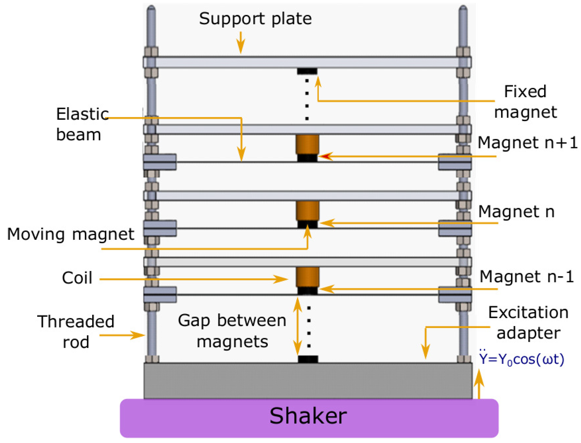
Figure 2.
Bending vibration mode of the coupled beam system subjected to variations in mass density by (a) 0% (periodic system), (b) 10% of the 2nd, 5th and 8th beams counting from the bottom, (c) 6% and (d) 10% of the 3rd, 6th and 9th beams counting from the bottom.
Figure 2.
Bending vibration mode of the coupled beam system subjected to variations in mass density by (a) 0% (periodic system), (b) 10% of the 2nd, 5th and 8th beams counting from the bottom, (c) 6% and (d) 10% of the 3rd, 6th and 9th beams counting from the bottom.
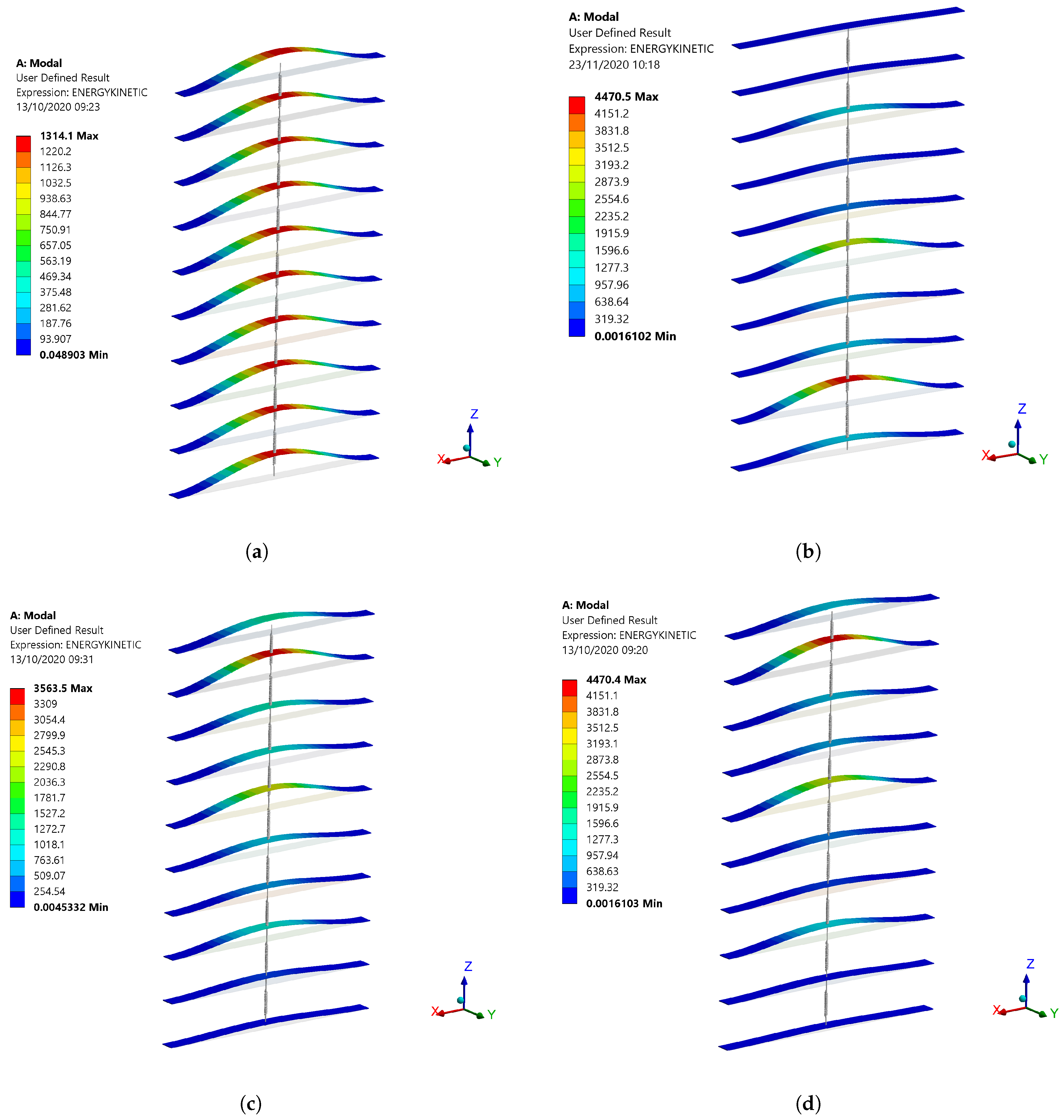
Figure 3.
(a) Numerical and experimental energies of the 1st and 2nd DOFs versus mass mistuning coefficient (arms = 1 g, Rload = 6Ω). (b) Harvested power from the perturbed magnet with load resistance (arms = 1 g, α = 1.06).
Figure 3.
(a) Numerical and experimental energies of the 1st and 2nd DOFs versus mass mistuning coefficient (arms = 1 g, Rload = 6Ω). (b) Harvested power from the perturbed magnet with load resistance (arms = 1 g, α = 1.06).
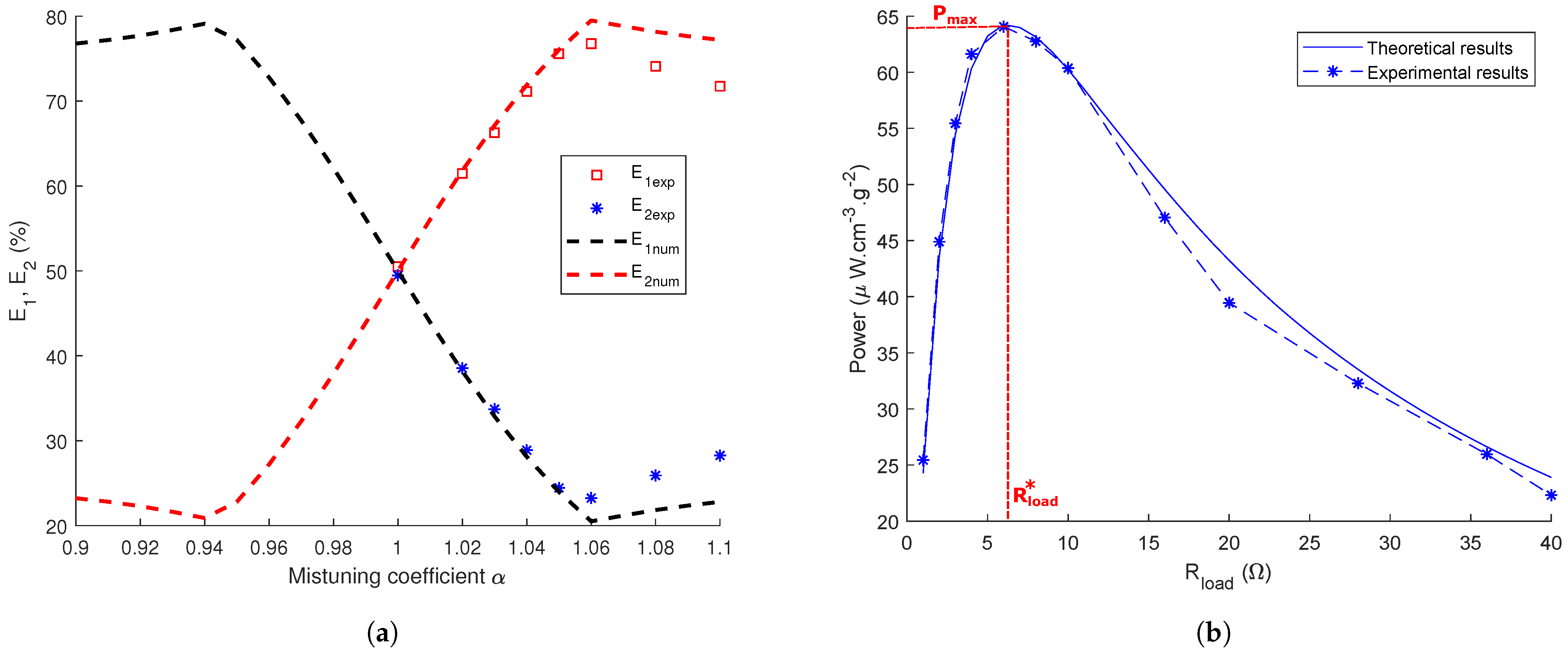
Figure 4.
Pareto front of the 2-DOFs system: frequency bandwidth versus harvested power.

Figure 5.
Experimental validation of the optimal configuration of the 2-DOFs model in terms of the average power and the corresponding frequency bandwidth BW.
Figure 5.
Experimental validation of the optimal configuration of the 2-DOFs model in terms of the average power and the corresponding frequency bandwidth BW.
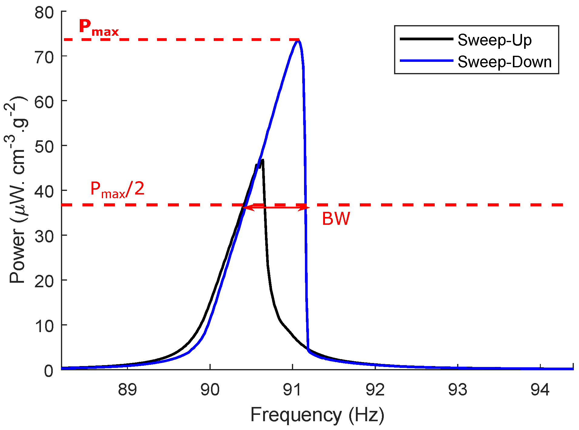
Figure 6.
The equivalent 5-DOFs model of the vibration energy harvester (VEH).
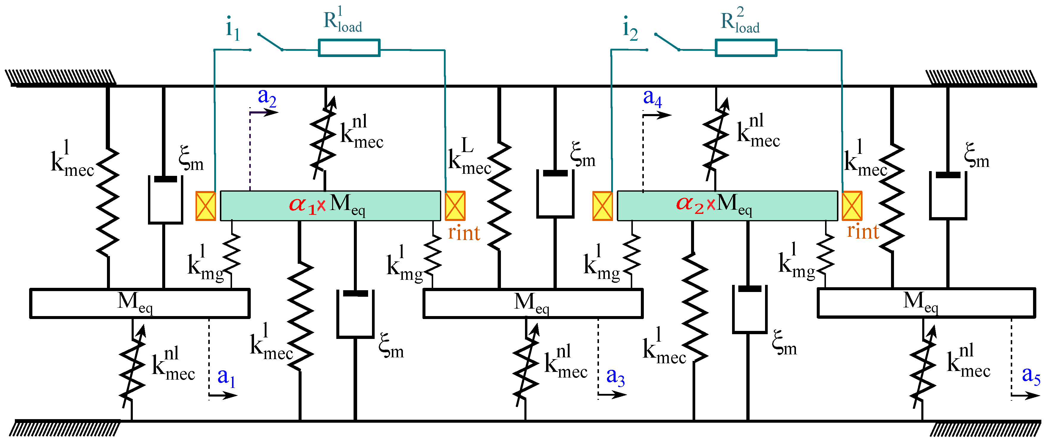
Figure 7.
(a) Pareto front of the 5-DOFs system: E2 versus E4. (b) Pareto front of the 5-DOFs system: frequency bandwidth versus harvested power with the corresponding energy localization rates in %.
Figure 7.
(a) Pareto front of the 5-DOFs system: E2 versus E4. (b) Pareto front of the 5-DOFs system: frequency bandwidth versus harvested power with the corresponding energy localization rates in %.
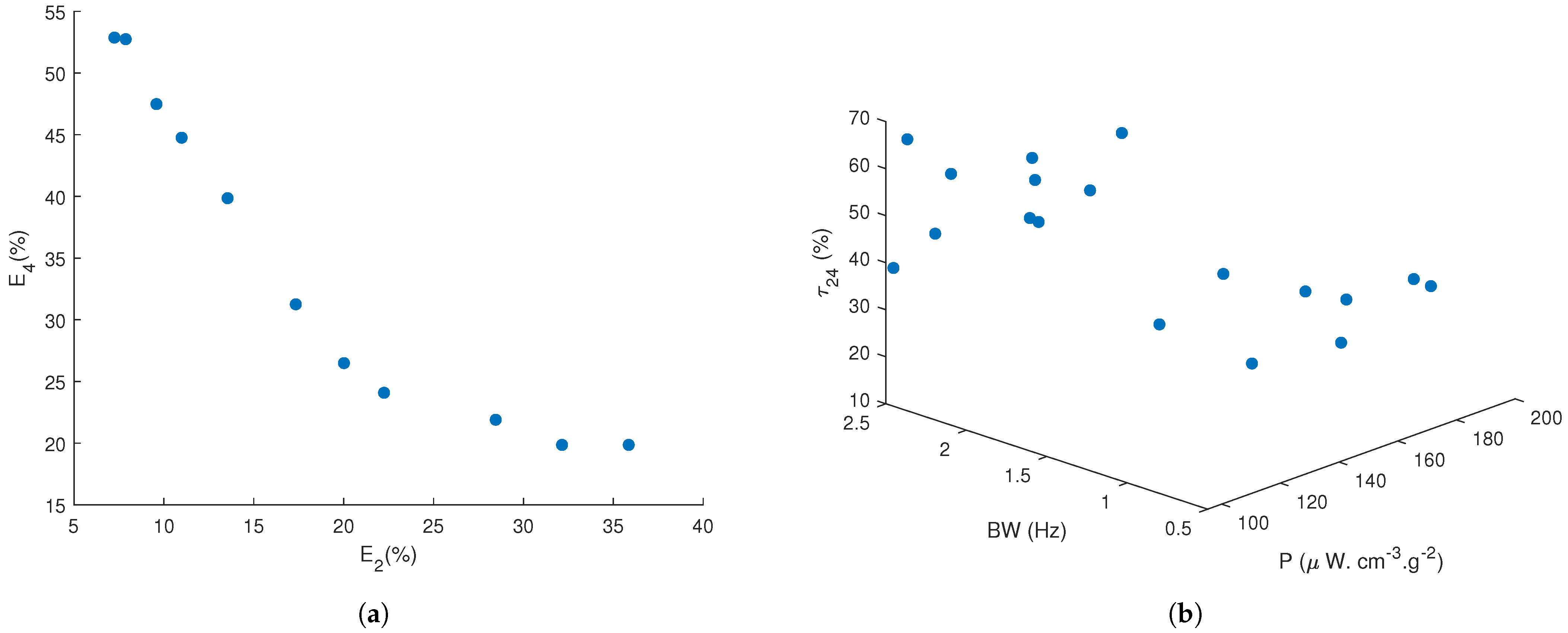
Figure 8.
(a) 2D projection of the Pareto front. (b) Harvested power of the optimal configuration.

Figure 9.
Pareto front of the periodic 5-DOFs system.

Figure 10.
Comparison of the optimized proposed harvester with the current state-of-the-art [23,35,50,51,52,53,54,55,56,57].


Table 1.
Natural eigenfrequencies of the 10-beams system in .
| 120.8924 | 120.8996 | 120.9109 | 120.9253 | 120.9418 | 120.9590 | 120.9756 | 120.9900 | 121.0013 | 121.0084 |
Table 2.
Objective function and constraints applied to the optimization problem for the 2-DOFs harvester.
Table 2.
Objective function and constraints applied to the optimization problem for the 2-DOFs harvester.
| Objective Function |
|---|
| Maximize: (P, BW) = f (, , ) |
| Constraints |
| 1 ≤ ≤ |
| ≤ |
| < |
Table 3.
Results of the multiobjective optimization of the 2-DOFs harvester.
| Compromise Solution |
|---|
| (, ) = ( μW·cmg, Hz) |
| With |
Table 4.
Objective function and constraints applied to search for the position of the mistuning.
| Objective Function |
|---|
| Maximize: P = f (, , , , ) |
| Constraints |
| 1 ≤ ≤ |
| ≤ |
| < ≤ 40 |
Table 5.
Objective function and constraints applied to the optimization problem for the 5-DOFs harvester.
Table 5.
Objective function and constraints applied to the optimization problem for the 5-DOFs harvester.
| Objective Function |
|---|
| Maximize: (P, BW, ) = f (, , , , ) |
| Constraints |
| 1 ≤ ≤ |
| ≤ |
| < ≤ 40 |
Table 6.
Results of the optimization problem of the 5-DOFs harvester.
| Compromised Solution |
|---|
| (, ,) = ( μW·cm·g, 1.87 Hz, ) |
| With |
Publisher’s Note: MDPI stays neutral with regard to jurisdictional claims in published maps and institutional affiliations. |
© 2021 by the authors. Licensee MDPI, Basel, Switzerland. This article is an open access article distributed under the terms and conditions of the Creative Commons Attribution (CC BY) license (http://creativecommons.org/licenses/by/4.0/).
Share and Cite
MDPI and ACS Style
Aouali, K.; Kacem, N.; Bouhaddi, N.; Haddar, M. On the Optimization of a Multimodal Electromagnetic Vibration Energy Harvester Using Mode Localization and Nonlinear Dynamics. Actuators 2021, 10, 25. https://doi.org/10.3390/act10020025
AMA Style
Aouali K, Kacem N, Bouhaddi N, Haddar M. On the Optimization of a Multimodal Electromagnetic Vibration Energy Harvester Using Mode Localization and Nonlinear Dynamics. Actuators. 2021; 10(2):25. https://doi.org/10.3390/act10020025
Chicago/Turabian StyleAouali, Kaouthar, Najib Kacem, Noureddine Bouhaddi, and Mohamed Haddar. 2021. "On the Optimization of a Multimodal Electromagnetic Vibration Energy Harvester Using Mode Localization and Nonlinear Dynamics" Actuators 10, no. 2: 25. https://doi.org/10.3390/act10020025
Note that from the first issue of 2016, this journal uses article numbers instead of page numbers. See further details here.