
A Novel Rotation-Structure Based Stick-Slip Piezoelectric Actuator with High Consistency in Forward and Reverse Motions


Key Laboratory of CNC Equipment Reliability, Ministry of Education, School of Mechanical and Aerospace Engineering, Jilin University, Changchun 130022, China
*
Authors to whom correspondence should be addressed.
Actuators 2021, 10(8), 189; https://doi.org/10.3390/act10080189
Submission received: 23 June 2021
/
Revised: 25 July 2021
/
Accepted: 4 August 2021
/
Published: 8 August 2021
(This article belongs to the Special Issue Design of Sensing and Actuation Systems)
Abstract
:Under the same driving voltage and frequency, the forward and reverse motion inconsistency of stick-slip piezoelectric actuators would bring difficulty for subsequent control. To solve this problem, a rotation-structure based piezoelectric actuator with completely symmetric structure and two driving feet was initially proposed. By testing its output performances under various driving voltages and frequencies, it was confirmed that, although similar speeds could be achieved for forward and reverse motions, the maximum displacement and backward displacement in each step were still quite different. By analyzing the reasons leading to this difference, this actuator was further improved by using only one driving foot. The experimental results showed that the forward and reverse motion consistency of the improved actuator had been significantly improved. The deviation rate was only 1.6%, corresponding to a travel distance of 118.7 μm, obtained under the driving voltage of 100 V and driving frequency of 10 Hz. The comparison with some previously reported actuators further confirmed the advancement of this improved actuator.
1. Introduction
Precision positioning and driving technology has huge development prospects in future microscopic research work. In micro–nano manipulation, precision manufacturing, micro electro mechanical systems, in situ mechanical testing of materials, and many other high-tech fields, it has already been widely utilized [1,2,3,4,5]. Using the inverse piezoelectric effect of piezoelectric materials, various piezoelectric actuators have been developed to meet the requirements of precision positioning. To achieve large-stroke movement, several stepping piezoelectric driving principles have been proposed, which can be classified by the working principles of inchworm actuators [6,7], stick-slip actuators [8,9], impact actuators [10,11], ultrasound actuators [12,13], and so on. Compared with other types of actuators, stick-slip piezoelectric actuators have the advantages of simple structure and convenient control; therefore, they have been widely investigated in recent years.
Up to now, various methods have been employed to improve the performances of stick-slip piezoelectric actuators. For example, to achieve compact structure and easy controllability, the actuator consisting of just one drive foot and a multilayer PZT bimorph had been proposed [14]. To suppress the backward motion, resonant/off-resonant hybrid excitation signals had been adopted [15]. To improve the motion speed, many new driving mechanisms had been designed [16,17,18,19]. In addition, some ingenious control methods had been used to improve positioning accuracy [20,21]. Apart from the above examples, many innovative studies have been performed, and all these studies greatly promoted the development of stick-slip piezoelectric actuators.
However, for many previously reported stick-slip actuators, one problem exists, i.e., it is difficult for the output performances of forward motions to be consistent with those of the opposite direction [22,23,24,25,26]. Under the same driving voltage and driving frequency, the inconsistency in forward and reverse motions would bring complex control problems. In order to achieve consistency in forward and reverse motions, different control parameters have to be employed. Generally, for most previous stick-slip actuators, the asymmetric structure is one main reason leading to the inconsistency in forward and reverse motions. In [24], due to the asymmetric structure, the forward motion speed is 0.30 mm/s and the reverse motion speed is 0.37 mm/s under the driving voltage of 100 V and driving frequency of 10 Hz, which has quite a large deviation rate of 20.90%. To solve this problem, some stick-slip piezoelectric actuators used two identical driving mechanisms, which were assembled symmetrically. In [22], however, after 50 steps of forward motions and 50 steps of reverse motions, the deviation in angular displacements was 376.4 μrad, and the deviation rate was 10.75%. Owing to the independence of the forward driving module and the reverse driving module of the actuator, huge assembly error is inevitable, as well as the manufacturing error. Therefore, it is quite difficult to achieve good consistency in the two directions.
Accordingly, in this paper, a piezoelectric actuator with a rotation-structure is proposed to solve the problem of inconsistency in forward and reverse motions. This paper is divided into the following sections. Section 1 introduces the research background and the significance of this work. Section 2 introduces the structure and motion principle of the proposed actuator. The theoretical calculation is given in Section 3. Section 4 presents the experiments and discussion of the designed actuator, and, in this section, another improved actuator is proposed to obtain better consistency in forward and reverse motions. The improved structure and original structure form a comparison to demonstrate the high consistency of the improved prototype. Finally, the conclusion is given in Section 5.
2. Structure and Motion Processes of the Designed Actuator
2.1. Structure of the Designed Actuator
Figure 1 shows the model of the proposed piezoelectric actuator. It consists of a stator, a slider, a base, a fill block, and a pre-tightening platform. The pre-tightening platform and the fill block are directly installed on the base; the slider and the stator are installed on the pre-tensioning platform and the fill block, respectively. The fill block ensures that the stator and the slider are on the same height. The pre-tightening platform is used to adjust the contact between the slider and the stator by adjusting the knob.
The stator is the key component that drives the slider to move, and its detailed structure is shown in Figure 1b. It mainly consists of a biped flexible hinge mechanism (X-shaped), a fixed plate, two piezoelectric stacks (PES 1 and PES 2, AE0505D16F, TOKIN, Japan), wedge blocks, a bearing, and a vertical shaft. The two ends of the vertical shaft are interference-fitted to the fill block and the inner race of the bearing, respectively; the bipedal flexible hinge mechanism is interference-fitted to the outer race of the bearing. Therefore, the biped flexible hinge mechanism can rotate freely around the bearing. The fixing plate is fixed on the fill block. PES 1 and PES 2 are pre-tightened between the biped flexible hinge mechanism and the fixed plate by wedge blocks.
This section may be divided by subheadings. It provides a concise and precise description of the experimental results, their interpretation, as well as the experimental conclusions that can be drawn.
2.2. Motion Principle
After assembly, the two driving feet of the stator will contact the slider at the same time. When a sawtooth driving voltage, as illustrated in Figure 2, is applied to the PES 1, the left driving foot will drive the slider to move along the positive x-axis. When the same sawtooth driving voltage is applied to the PES 2, the right driving foot will drive the slider to move along the negative x-axis.
Corresponding to the sawtooth driving voltage shown in Figure 2, the forward and reverse motion processes of the actuator are illustrated in Figure 3a–f, respectively. Taking the forward motion (i.e., the motion along the positive x-axis) as an example, it mainly includes the following three steps.
Step 1: At time t0, the driving voltage is zero, and the actuator is in its initial status, as shown in Figure 3a.
Step 2: From time t0 to t1, the driving voltage is gradually increased, and the PES 1 will gradually extend and push the left driving foot to rotate around the bearing. The left driving foot drives the slider to move a small distance ∆s along the positive x-axis, as illustrated in Figure 3b.
Step 3: From time t1 to t2, the driving voltage drops to zero rapidly. The PES 1 and the biped flexible hinge mechanism respond to the signal quickly and retract to their original status promptly. As shown in Figure 3c, owing to the inertia of the slider, it will almost remain in position.
After one cycle, the slider moves ∆s along the positive x-axis. Repeating this process, the slider will achieve a large forward motion step by step. With regard to the reverse motion, its process is similar to that illustrated in Figure 3d–f.
3. Theoretical Calculation
According to the structure and motion principle shown in Section 2, the X-shaped flexible hinge mechanism is the key component of the actuator. Therefore, theoretical analysis of this mechanism is performed, and Figure 4 shows the theoretical model and structural parameters.
In Figure 4, points C and D represent the contact points of the driving feet and the slider. Point O represents the position of the bearing, which is a fixed point. Points A and B are the displacement input points from these two PESs. The lengths of lines OC and OD are defined as L1, and the lengths of lines OA and OB are defined as L2. The input displacement from PES 2 at point A is expressed as δ, and the corresponding output displacement at point D is expressed as s. θ represents the rotation angle of the X-shaped flexible hinge mechanism.
According to the similarity of triangles, the parameters s, L1, L2, and δ have the following relationship:
As δ is far less than L2, the angle θ can be approximatively expressed as
As the angle θ is very small, the angle α can be obtained from the geometric relationship illustrated in Figure 4b as
According to the above formulae, the projection displacements of the output displacement s along the x- and y-axes, i.e., Δx and Δy, can be calculated as
The projection displacement Δy will make the slider and the tip of driving foot contact more tightly, and the projection displacement Δx will make the tip of the driving foot stick the slider to realize movement.
The magnification ratio λ of the X-shaped flexible hinge mechanism is obtained as
The main structure parameters of the X-shaped flexible hinge mechanism are listed in Table 1.
By the parameters L1 and L2, the magnification ratio λ is calculated to be 1.10. By experimental measurement under the driving voltage and frequency of 100 V and 10 Hz, the parameters s and δ are 12.23 μm and 14.35 μm, respectively; accordingly, the magnification ratio λ is calculated to be 1.17. The deviation rate between them is only about 6.36%, which verifies the effectiveness of the theoretical calculation.
4. Experiments and Analysis
4.1. Experimental System
To test the output performances of the proposed actuator and, as well, verify the consistency in forward and reverse motions, an actuator prototype was manufactured and an experimental system was established, as shown in Figure 5. The biped flexible mechanism was fabricated by 7075 aluminum alloy to ensure good mechanical properties. During experiments, the sawtooth driving voltage was generated by the signal generator (DG4062, RIGOL Technologies, China), amplified by the voltage amplifier (E01.A3, Harbin Core Tomorrow Science & Technology Co., Ltd., Harbin, China), and finally applied to the PES. The displacement of the slider was measured by the laser sensor (ILD2300-2, Micro-Epsilon, Free State of Bavaria, Germany) with a resolution of 0.03 μm at 20 kHz and absolute error at less than ±0.6 μm, and the collected data was further analyzed by the computer.
4.2. Output Performances under Various Driving Voltages and Frequencies
The driving voltage and frequency are two main parameters that affect output performances. So, their effects were tested first. Here, the motion along the positive x-axis is defined as the forward motion, and the motion along the negative x-axis is the reverse motion. Figure 6a presents the forward and reverse output displacements changing with time obtained under the fixed driving frequency of 10 Hz and various driving voltages (60–140 V), and Figure 6b shows the forward and reverse output displacements changing with time obtained under the fixed driving voltage of 100 V and various driving frequencies (1–10 Hz). It is clearly seen that, in each step, after reaching the one-stepping maximum displacement, there is a small backward displacement. These two displacements correspond to the “stick” and “slip” processes, respectively, and the one-stepping effective displacement is their difference value. In Figure 6a, under the driving voltage of 100 V and frequency of 10 Hz, the one-stepping effective displacement for forward direction is 3.43 μm, and it is 3.44 μm for the reverse motion. The difference is very small, which means it has good consistency.
Although the one-stepping effective displacement of forward and reverse motions has good consistency, the differences in one-stepping maximum displacement and the backward displacement are large. For example, under the driving voltage of 140 V and frequency of 10 Hz, the one-stepping maximum displacement is 7.43 μm and the backward displacement is 2.09 μm for the forward motion; however, for the reverse motion, they are 10.49 μm and 5.22 μm, respectively. As shown in Figure 6b, when fixing the driving voltage and changing the driving frequency, the differences in one-stepping maximum displacement and the backward displacement for forward and reverse motions are more remarkable.
By analyzing the structure, fabrication, assembly, and experimental processes, the differences in one-stepping maximum displacement and the backward displacement for forward and reverse motions could be a result of the assembly process. Although the actuator is designed with a completely symmetrical structure, it is difficult for the contact points between the slider and driving feet, as well as the contact status between the PESs and the flexible mechanisms, to be adjusted to be exactly the same. Therefore, the difference in forward and reverse motions appears. Figure 7a,b show the effects of driving voltage and frequency on the forward and reverse speeds. In a more direct way, it can be further proved that there is some consistency in forward and reverse movements in the macroscopic motion of the actuator by this figure. Furthermore, the consistency is better when the driving voltage and frequency are relatively low; however, the consistency is poor when the driving frequency is high. The main reason for this phenomenon is the increased vibration at high driving frequencies.
According to the above results and analysis, to further improve the consistency, an improved actuator is proposed in Section 4.3.
4.3. The Actuator with One Driving Foot
For the above actuator with two driving feet, it is difficult to keep the contact status between the slider and the two driving feet exactly the same; thus, the possibility of the inconsistency of forward and reverse motions increases. To solve the problem caused by bipedal machining and assembly errors, a flexible hinge mechanism with one driving foot is designed to replace the flexible hinge mechanism with two driving feet, and, accordingly, an improved actuator is developed, as shown in Figure 8a. Figure 8b illustrates the deformation diagram of the stator. This actuator has no difference with the former actuator except the number of driving feet. As only one driving foot exists, only the contact status between the PESs and the flexible mechanism needs to be adjusted to make the output force on both sides nearly the same. Compared to the former actuator, the adjusting processes are more convenient.
4.3.1. Output Performances under Different Voltages and Frequencies
The output performances under different voltages were tested under the fixed driving frequency of 10 Hz. Pre-experiments indicate that, when the driving voltage is less than 60 V, this actuator could not work stably. Therefore, Figure 9a presents the forward and reverse cumulative displacements of 40 steps corresponding to the driving voltages of 60, 80, 100, 120, and 140 V, and Figure 9b shows the motion speed changing with the driving voltage. Table 2 lists the detailed forward and reverse displacements of 40 steps obtained under various driving voltages, and the deviations between forward and reverse displacements are also analyzed. From Figure 9 and Table 2, it could be clearly seen that the improved actuator has high consistency in forward and reverse motions under various driving voltages.
For quantitative analysis and comparison, another parameter, i.e., the deviation rate e is defined, which is calculated by the following equation
where dF is the forward displacement and dR is the reverse displacement.
All the deviation rates are less than 2% when increasing the driving voltage from 60 V to 100 V with an interval of 20 V. This slight deviation may be due to the different frictions in these two directions, caused by the assembly and manufacturing errors of the prototype.
To more clearly present the characteristics of forward and backward motions in one step, Figure 10 illustrates the accumulative displacement of the actuator in 10 steps. In this figure, the forward and backward motions of each step are almost the same, which further demonstrates that the improved actuator has high forward and backward consistency in each step and can achieve very stable stepping motion. For example, under the driving voltage of 140 V and driving frequency of 10 Hz, the one-stepping maximum displacement is 6.62 μm and the backward displacement is 3.05 μm for the forward motion. For the reverse motion, they are 6.50 μm and 2.96 μm, respectively. Comparing Figure 10 and Figure 6a, is proof that, when using only one driving foot, the consistency in forward and reverse motions was significantly improved, presenting a very similar one-stepping maximum displacement and backward displacement. The detailed one-stepping maximum displacement and the backward displacement of the actuators are listed in Table 3, which clearly shows the difference between the two actuators.
In addition, the forward and reverse motion consistency of the improved actuator was further characterized under the fixed driving voltage of 100 V and various driving frequencies. Firstly, the relatively low frequencies, varying from 1 to 10 Hz, are selected, and the measured displacement–time curves are presented in Figure 11a. Figure 11b shows the corresponding speed–frequency curves. It is seen that the improved actuator is able to maintain high consistency in forward and reverse motions under relatively low driving frequencies. Table 4 lists the detailed forward and reverse accumulative displacements in 5 s, as well as the deviations and deviation rates. The deviation rates are around 2%, which further proves that the actuator keeps high forward and reverse motion consistency under the frequency range of 1 to 10 Hz.
The above results are obtained under relatively low driving frequencies, and the improved actuator shows good consistency in forward and reverse motions. Then, the forward and reverse motion consistency under relatively high driving frequencies—up to 100 Hz—was further characterized under the fixed driving voltage of 100 V. When the driving frequency was over 100 Hz, the individual step in forward and backward motions could not be clearly distinguished, so output performances under a higher driving frequency were not measured. Figure 12a presents the output displacements in 500 ms, corresponding to the driving frequency range of 10 to 100 Hz, and Figure 12b shows the corresponding motion speed changing with the driving frequency. Table 5 lists the detailed forward and reverse accumulative displacements in 500 ms, as well as the deviations and deviation rates. From Figure 12 and Table 5, it can be confirmed that the improved actuator still has high forward and reverse motion consistency under relatively high frequencies. In addition, when the frequency is below 100 Hz, the deviation rate fluctuates in a very small range, but when the driving frequency is 100 Hz, the deviation is apparently higher than those obtained under other frequencies. This could be due to the following reasons: (1) under high frequency, the contact between the slider and the tip of the driving foot may not be stable due to high vibration; (2) the deviation in each step is accumulated, and, for the same time, the high frequency leads to a larger deviation and further results in a higher deviation rate.
4.3.2. Comparison
Table 6 shows the comparison in deviation and deviation rate between some previously proposed actuators and the actuators developed in this study. Compared to those actuators reported in [27,28], both the actuators with two driving feet and one driving foot have quite low deviation rates, even for longer travel distances. Even though the deviation rates (2.1% and 1.6%) are close to that of the actuator reported in [29], the employed driving frequency is 10 Hz, and it is only 1 Hz for [29]. It is noted that, even under a higher driving frequency of 100 Hz, the actuator with one driving foot keeps high forward and reverse motion consistency with the deviation rate of 4.2%, and the used driving frequencies of other reported actuators are all 1 Hz. This suggests that the improved actuator is able to retain good forward and reverse motion consistency in a relatively wide frequency range.
Moreover, when comparing the actuator with two driving feet with that with one driving foot, it is seen that, even for a longer travel distance (118.7 μm), the actuator with one driving foot shows a lower deviation rate. Therefore, the forward and reverse motion consistency has been significantly improved by using only one driving foot.
5. Conclusions
In summary, to achieve good forward and reverse motion consistency, a stick-slip piezoelectric actuator with a completely symmetric structure was designed first, which employed an X-shaped flexible hinge mechanism to realize the forward and reverse motions. The working principle of the actuator and structural analysis of the flexible hinge mechanism was discussed in detail, followed by measuring and evaluating its forward and reverse motion performances under various driving voltages and frequencies. The results indicated that, although some consistency in forward and reverse movements was achieved in macroscopic motion, the differences in one-stepping maximum displacement and the backward displacement were still remarkable. After analyzing the possible reasons leading to these differences, an improved actuator with only one driving foot was proposed. The experimental results indicated that the improved actuator was able to keep very high consistency in forward and reverse motions, even under relatively high driving frequency. The deviation rate was only 1.6%, corresponding to a travel distance of 118.7 μm, obtained under the driving voltage of 100 V and driving frequency of 10 Hz. Comparative analysis with the actuator with two driving feet and some previously reported actuators demonstrated that the actuator with one driving foot had improved consistency in forward and reverse motions, which would be beneficial to its practical application.
Author Contributions
Conceptualization, H.H. and J.T.; methodology, H.H.; software, J.T.; validation, J.T., J.W., and Y.W.; formal analysis, Y.W.; investigation, J.W.; resources, Z.X.; data curation, Y.W.; writing—original draft preparation, J.T.; writing—review and editing, H.H.; supervision, H.H.; project administration, J.T.; funding acquisition, H.H. All authors have read and agreed to the published version of the manuscript.
Funding
This work was supported by the National Natural Science Foundation of China (Grant No. 52075221), the Young Elite Scientists Sponsorship Program by CAST (YESS) (Grant No. 2017QNRC001), and the Fundamental Research Funds for the Central Universities (2019–2021).
Institutional Review Board Statement
Not applicable.
Informed Consent Statement
Not applicable.
Data Availability Statement
The data presented in this study are available on request from the corresponding author. The data are not publicly available due to privacy.
Conflicts of Interest
The authors declare no conflict of interest.
References
- Sun, L.; Wang, J.; Rong, W.; Li, X.; Bao, H. A silicon integrated micro nano-positioning XY-stage for nano-manipulation. J. Micromech. Microeng. 2008, 18, 125004. [Google Scholar] [CrossRef]
- Xu, D.; Liu, Y.; Shi, S.; Liu, J.; Chen, W.; Wang, L. Development of a Nonresonant Piezoelectric Motor With Nanometer Resolution Driving Ability. IEEE/ASME Trans. Mechatron. 2018, 23, 444–451. [Google Scholar] [CrossRef]
- Zhang, L.; Xiong, Z.; Lai, J.; Liu, J. Optical flow-aided navigation for UAV: A novel information fusion of integrated MEMS navigation system. Optik 2016, 127, 447–451. [Google Scholar] [CrossRef]
- Verma, S.; Kim, W.; Shakir, H. Multi-Axis Maglev Nanopositioner for Precision Manufacturing and Manipulation Applications. IEEE Trans. Ind. Appl. 2005, 41, 1159–1167. [Google Scholar] [CrossRef]
- Huang, H.; Zhao, H.; Shi, C.; Wu, B.; Fan, Z.; Wan, S.; Geng, C. Effect of residual chips on the material removal process of the bulk metallic glass studied by in situ scratch testing inside the scanning electron microscope. AIP Adv. 2012, 2, 042193. [Google Scholar] [CrossRef]
- Li, J.; Zhao, H.; Qu, H.; Cui, T.; Fu, L.; Huang, H.; Ren, L.; Fan, Z. A piezoelectric-driven rotary actuator by means of inchworm motion. Sens. Actuators A Phys. 2013, 194, 269–276. [Google Scholar] [CrossRef]
- Song, S.; Shao, S.; Xu, M.; Shao, Y.; Tian, Z.; Feng, B. Piezoelectric inchworm rotary actuator with high driving torque and self-locking ability. Sens. Actuators A Phys. 2018, 282, 174–182. [Google Scholar] [CrossRef]
- Huang, H.; Li, J.; Zhao, H.; Shi, C. On the correlation between the structure and one stepping characteristic of a piezo-driven rotary actuator. Microsyst. Technol. 2015, 22, 2821–2827. [Google Scholar] [CrossRef]
- Zhang, S.; Liu, J.; Deng, J.; Liu, Y. Development of a Novel Two-DOF Pointing Mechanism Using a Bending–Bending Hybrid Piezoelectric Actuator. IEEE Trans. Ind. Electron. 2019, 66, 7861–7872. [Google Scholar] [CrossRef]
- Mazeika, D.; Vasiljev, P.; Borodinas, S.; Bareikis, R.; Yang, Y. Small size piezoelectric impact drive actuator with rectangular bimorphs. Sens. Actuators A Phys. 2018, 280, 76–84. [Google Scholar] [CrossRef]
- Shao, Y.; Shao, S.; Xu, M.; Song, S.; Tian, Z. An inertial piezoelectric actuator with miniaturized structure and improved load capacity. Smart Mater. Struct. 2019, 28, 055023. [Google Scholar] [CrossRef]
- Liu, Y.; Yan, J.; Wang, L.; Chen, W. A Two-DOF Ultrasonic Motor Using a Longitudinal–Bending Hybrid Sandwich Transducer. IEEE Trans. Ind. Electron. 2019, 66, 3041–3050. [Google Scholar] [CrossRef]
- Watson, B.; Friend, J.; Yeo, L. Piezoelectric ultrasonic micro/milli-scale actuators. Sens. Actuators A Phys. 2009, 152, 219–233. [Google Scholar] [CrossRef]
- Chu, X.; Gao, S.; Zhong, Z.; Zhao, Y.; Li, L. Design and experiments of a miniature piezoelectric actuator using a multilayer PZT bimorph. Ferroelectrics 2017, 514, 114–122. [Google Scholar] [CrossRef]
- Cheng, T.; Li, H.; He, M.; Zhao, H.; Lu, X.; Gao, H. Investigation on driving characteristics of a piezoelectric stick–slip actuator based on resonant/off-resonant hybrid excitation. Smart Mater. Struct. 2017, 26, 035042. [Google Scholar] [CrossRef]
- Gao, Q.; He, M.; Lu, X.; Zhang, C.; Cheng, T. Simple and high-performance stick-slip piezoelectric actuator based on an asymmetrical flexure hinge driving mechanism. J. Intell. Mater. Syst. Struct. 2019, 30, 2125–2134. [Google Scholar] [CrossRef]
- Zhang, Y.; Peng, Y.; Sun, Z.; Yu, H. A Novel Stick–Slip Piezoelectric Actuator Based on a Triangular Compliant Driving Mechanism. IEEE Trans. Ind. Electron. 2019, 66, 5374–5382. [Google Scholar] [CrossRef]
- Guo, Z.; Tian, Y.; Zhang, D.; Wang, T.; Wu, M. A novel stick-slip based linear actuator using bi-directional motion of micropositioner. Mech. Syst. Signal Process. 2019, 128, 37–49. [Google Scholar] [CrossRef] [Green Version]
- Zhou, M.; Fan, Z.; Ma, Z.; Zhao, H.; Guo, Y.; Hong, K.; Li, Y.; Liu, H.; Wu, D. Design and Experimental Research of a Novel Stick-Slip Type Piezoelectric Actuator. Micromachines 2017, 8, 150. [Google Scholar] [CrossRef] [Green Version]
- Oubellil, R.; Voda, A.; Boudaoud, M.; Régnier, S. A 2-DOF H∞ control strategy for a 3 axes robotic system operating at the nanometer scale. In Proceedings of the 2016 20th International Conference on System Theory, Control and Computing (ICSTCC), Sinaia, Romania, 13–15 October 2016. [Google Scholar]
- Cheng, L.; Liu, W.; Yang, C.; Huang, T.; Hou, Z.-G.; Tan, M. A Neural-Network-Based Controller for Piezoelectric-Actuated Stick–Slip Devices. IEEE Trans. Ind. Electron. 2018, 65, 2598–2607. [Google Scholar] [CrossRef] [Green Version]
- Wang, S.; Rong, W.; Wang, L.; Pei, Z.; Sun, L. Design, analysis and experimental performance of a piezoelectric rotary actuator based on compliant foot driving. Microsyst. Technol. 2017, 23, 3765–3773. [Google Scholar] [CrossRef]
- Xu, Z.; Huang, H.; Dong, J. A stick-slip piezoelectric actuator with measurable contact force. Mech. Syst. Signal Process. 2020, 144, 106881. [Google Scholar] [CrossRef]
- Wang, K.; Li, X.; Sun, W.; Yang, Z.; Liang, T.; Huang, H. A novel piezoelectric linear actuator designed by imitating skateboarding movement. Smart Mater. Struct. 2020, 29, 115038. [Google Scholar] [CrossRef]
- Qin, F.; Huang, H.; Wang, J.; Tian, L.; Liang, T.; Zhao, H. Design and stepping characteristics of novel stick–slip piezo-driven linear actuator. Smart Mater. Struct. 2019, 28, 075026. [Google Scholar] [CrossRef]
- Li, Y.; Li, H.; Cheng, T.; Lu, X.; Zhao, H.; Chen, P. Note: Lever-type bidirectional stick-slip piezoelectric actuator with flexible hinge. Rev. Sci. Instrum. 2018, 89, 086101. [Google Scholar] [CrossRef] [PubMed]
- Wang, J.; Qin, F.; Zhang, Y.; Liang, T.; Wang, Z.; Xu, B.; Sun, Y.; Liu, X.; Zhao, H. Design, analysis and experiments of a linear piezoelectric actuator adopting a flexible mechanism with wing skeletal structure. Smart Mater. Struct. 2019, 28, 085034. [Google Scholar] [CrossRef]
- Wang, S.; Rong, W.; Wang, L.; Sun, L. Design, analysis and experimental performance of a stepping type piezoelectric linear actuator based on compliant foot driving. Smart Mater. Struct. 2016, 25, 115003. [Google Scholar] [CrossRef]
- Wang, J.; Qin, F.; Li, L.; Liu, Z.; Zhao, H. A linear piezoelectric actuator with high flexibility flexible mechanism designed by the bidirectional parasitic motion principle. Rev. Sci. Instrum. 2020, 91, 045005. [Google Scholar] [CrossRef]
Figure 1.
(a) Model of the proposed actuator, and (b) structure of the stator.

Figure 2.
The sawtooth driving voltage for the PES.
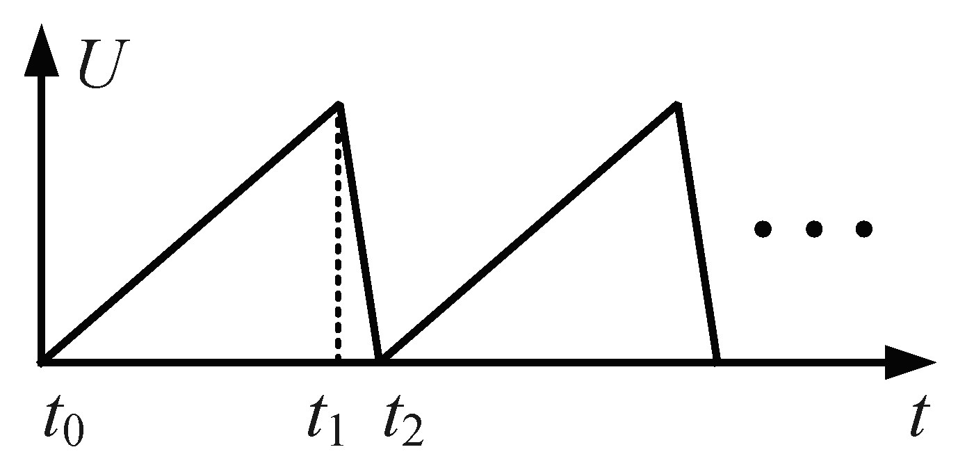
Figure 3.
Motion principle of the actuator. Figure 3a–c illustrate the motion processes along the positive x-axis (forward motion), and Figure 3d–f illustrate the motion processes along the negative x-axis (reverse motion).

Figure 4.
(a) Deformation schematic of the X-shaped flexible hinge mechanism, and (b) local enlarged view of the part I in Figure 4a.
Figure 4.
(a) Deformation schematic of the X-shaped flexible hinge mechanism, and (b) local enlarged view of the part I in Figure 4a.

Figure 5.
The experimental system.
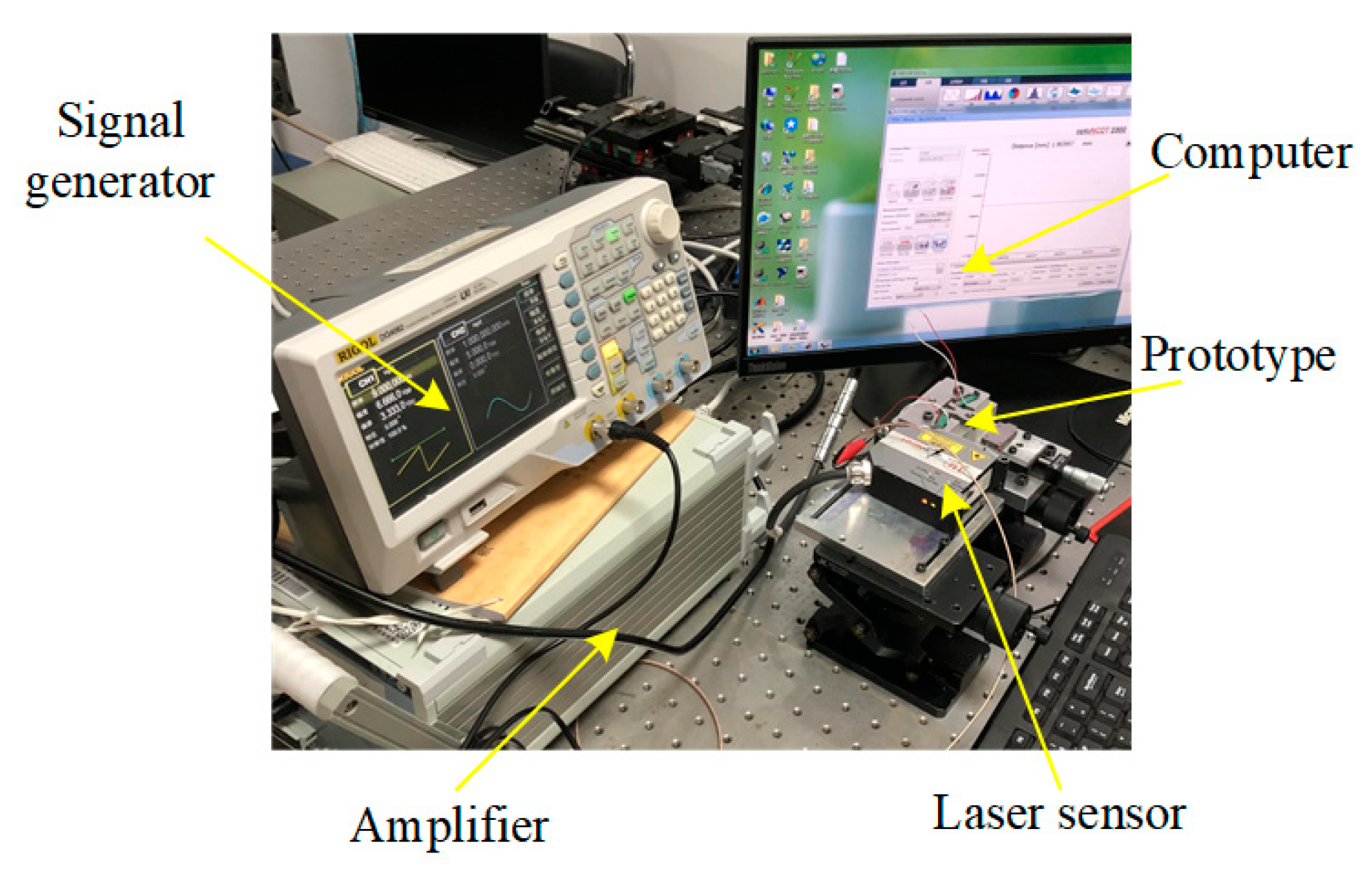
Figure 6.
(a) Forward and reverse output displacements obtained under the fixed driving frequency of 10 Hz and various driving voltages, and (b) forward and reverse output displacements obtained under the fixed driving voltage of 100 V and various driving frequencies.
Figure 6.
(a) Forward and reverse output displacements obtained under the fixed driving frequency of 10 Hz and various driving voltages, and (b) forward and reverse output displacements obtained under the fixed driving voltage of 100 V and various driving frequencies.
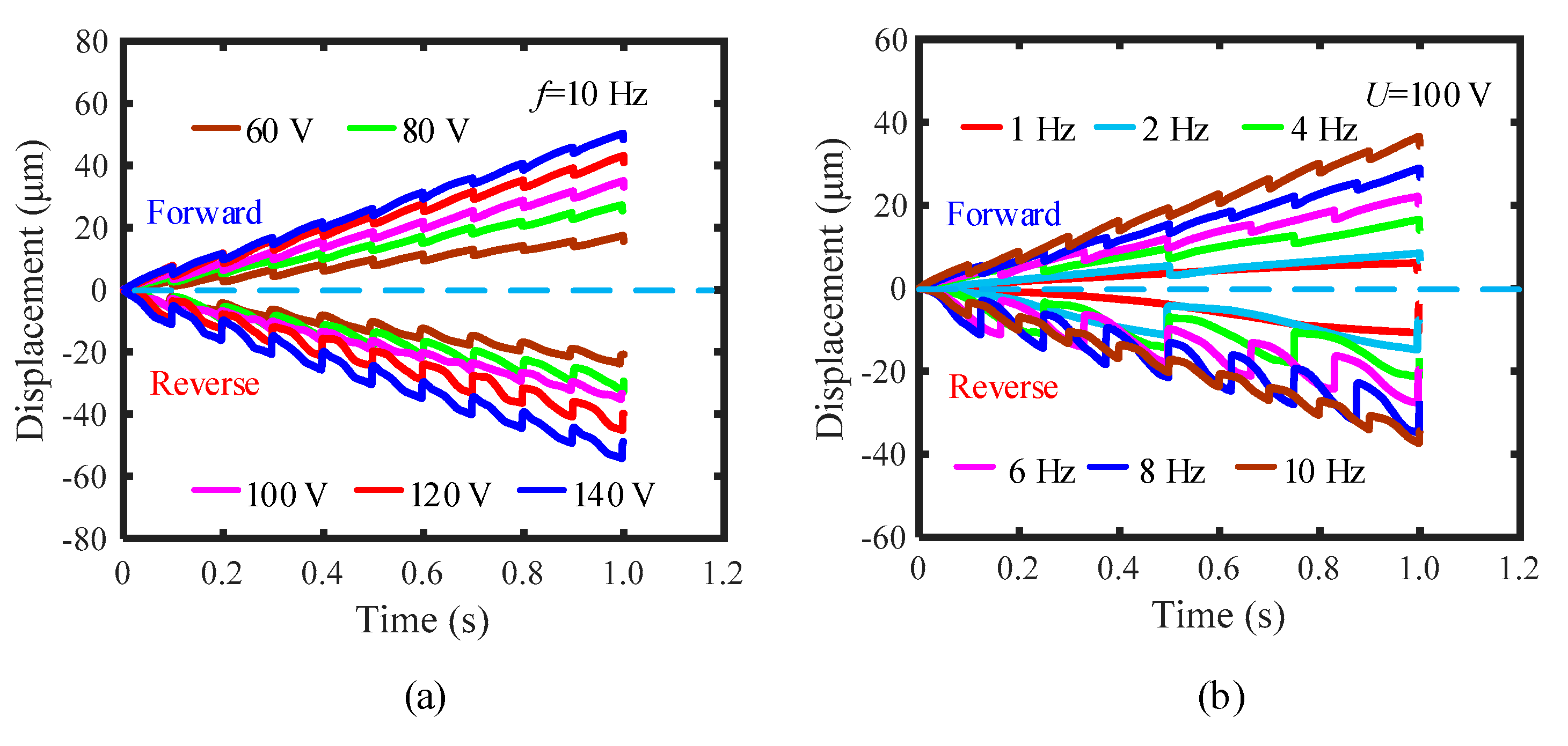
Figure 7.
(a) Forward and reverse speeds obtained under the fixed driving frequency of 10 Hz and various driving voltages, and (b) forward and reverse speeds obtained under the fixed driving voltage of 100 V and various driving frequencies.
Figure 7.
(a) Forward and reverse speeds obtained under the fixed driving frequency of 10 Hz and various driving voltages, and (b) forward and reverse speeds obtained under the fixed driving voltage of 100 V and various driving frequencies.
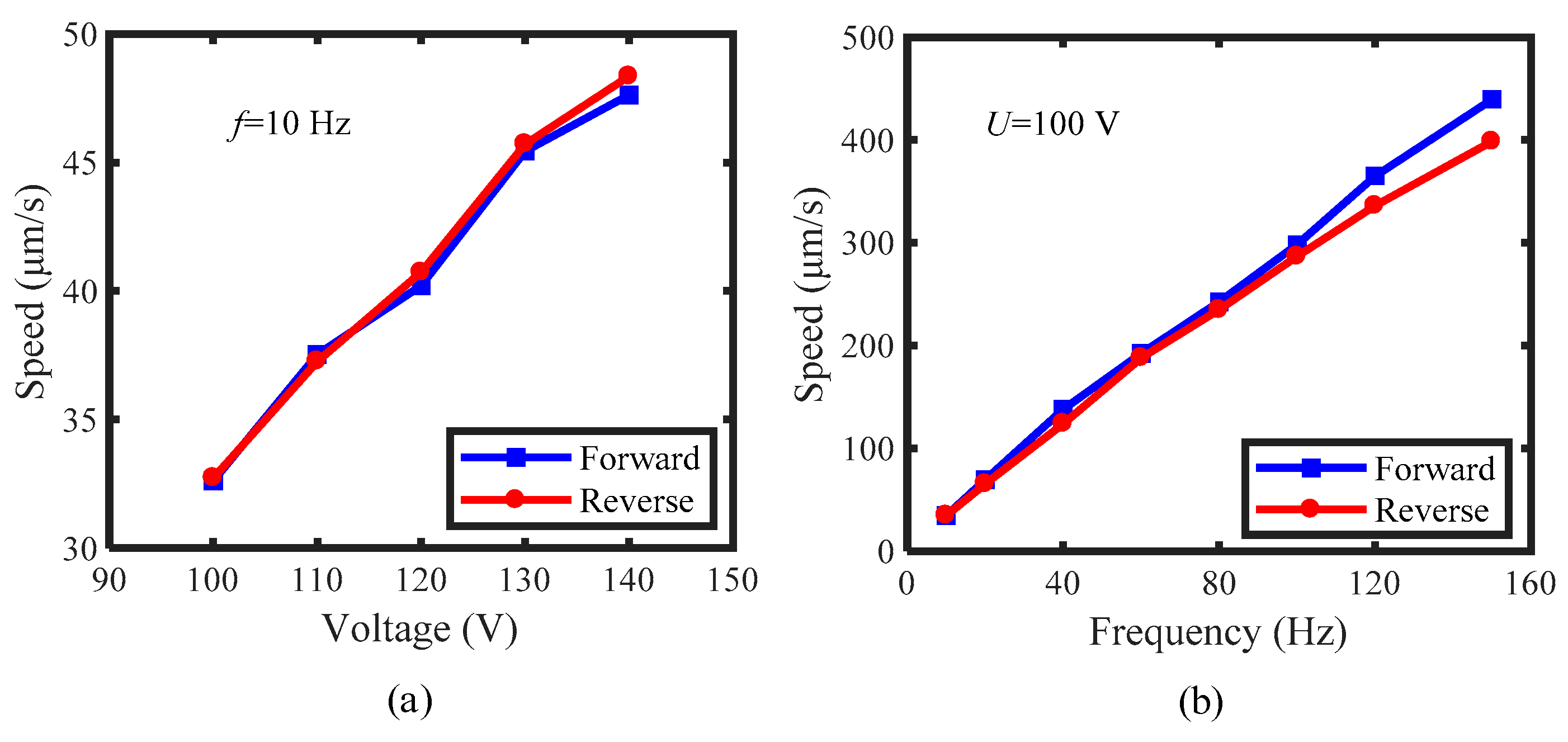
Figure 8.
(a) Model of the improved actuator with one driving foot, and (b) deformation diagram of the stator.
Figure 8.
(a) Model of the improved actuator with one driving foot, and (b) deformation diagram of the stator.

Figure 9.
(a) The forward and reverse cumulative displacements of the improved actuator in 40 steps obtained under the fixed driving frequency of 10 Hz and various driving voltages, and (b) the corresponding speed changing with the driving voltage.
Figure 9.
(a) The forward and reverse cumulative displacements of the improved actuator in 40 steps obtained under the fixed driving frequency of 10 Hz and various driving voltages, and (b) the corresponding speed changing with the driving voltage.
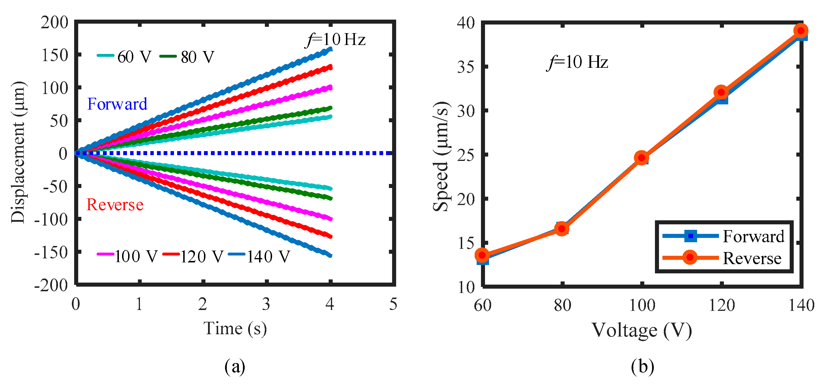
Figure 10.
The accumulative displacements of the improved actuator in 10 steps obtained under the fixed driving frequency of 10 Hz and various driving voltages.
Figure 10.
The accumulative displacements of the improved actuator in 10 steps obtained under the fixed driving frequency of 10 Hz and various driving voltages.

Figure 11.
(a) The forward and reverse cumulative displacements of the improved actuator in 5 s, obtained under the fixed driving voltage of 100 V and various driving frequencies (1 to 10 Hz), and (b) the corresponding speed changing with the driving frequency.
Figure 11.
(a) The forward and reverse cumulative displacements of the improved actuator in 5 s, obtained under the fixed driving voltage of 100 V and various driving frequencies (1 to 10 Hz), and (b) the corresponding speed changing with the driving frequency.
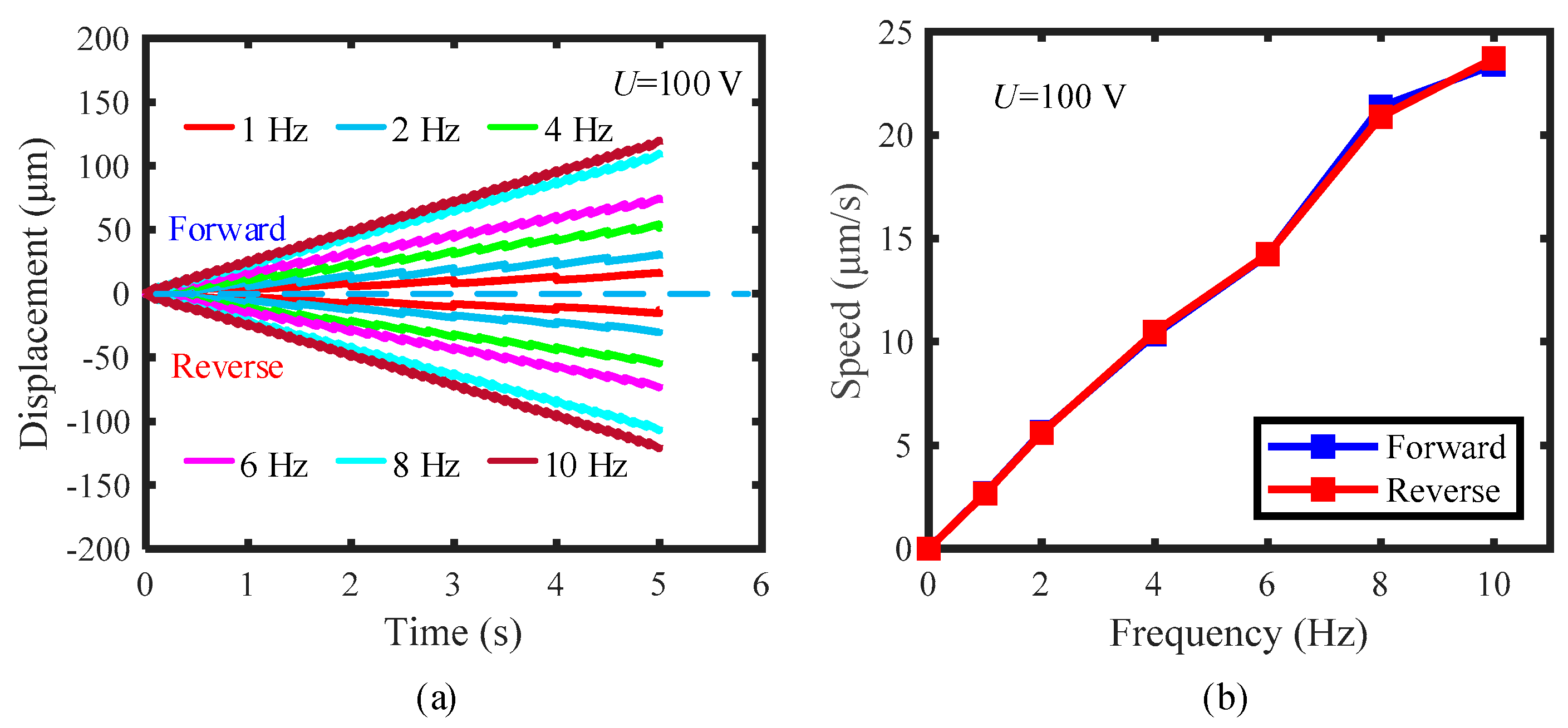
Figure 12.
(a) The forward and reverse cumulative displacements of the improved actuator in 500 ms, obtained under the fixed driving voltage of 100 V and various driving frequencies (10 to 100 Hz), and (b) the corresponding speed changing with the driving frequency.
Figure 12.
(a) The forward and reverse cumulative displacements of the improved actuator in 500 ms, obtained under the fixed driving voltage of 100 V and various driving frequencies (10 to 100 Hz), and (b) the corresponding speed changing with the driving frequency.


Table 1.
The main structure parameters of the X-shaped flexible hinge mechanism.
| Parameter | Value | Unit |
|---|---|---|
| L1 | 20.42 | mm |
| L2 | 18.42 | mm |
Table 2.
The detailed forward and reverse displacements of 40 steps obtained under various driving voltages, as well as the deviation analysis.
Table 2.
The detailed forward and reverse displacements of 40 steps obtained under various driving voltages, as well as the deviation analysis.
| Voltage (V) | Forward Displacement (μm) | Reverse Displacement (μm) | Deviation (μm) | Deviation Rate (%) |
|---|---|---|---|---|
| 60 | 54.11 | 53.52 | 0.59 | 1.1 |
| 80 | 66.88 | 66.74 | 0.14 | 0.21 |
| 100 | 98.35 | 97.97 | 0.38 | 0.39 |
| 120 | 129.28 | 126.93 | 2.35 | 1.8 |
| 140 | 153.99 | 152.95 | 1.04 | 0.68 |
Table 3.
The one-stepping maximum displacement and the backward displacement of the actuators with one driving foot and two driving feet under different driving voltages and frequencies (unit: μm).
Table 3.
The one-stepping maximum displacement and the backward displacement of the actuators with one driving foot and two driving feet under different driving voltages and frequencies (unit: μm).
| Actuator with Two Driving Feet | Actuator with One Driving Foot | |||||||
|---|---|---|---|---|---|---|---|---|
| Voltage or Frequency | One-Stepping Maximum Displacement | Backward Displacement | One-Stepping Maximum Displacement | Backward Displacement | ||||
| Forward | Reverse | Forward | Reverse | Forward | Reverse | Forward | Reverse | |
| 60 V | 3.82 | 2.09 | 5.22 | 2.85 | 3.31 | 1.96 | 3.26 | 1.91 |
| 100 V | 5.66 | 2.23 | 7.65 | 4.21 | 4.72 | 2.28 | 4.68 | 2.24 |
| 140 V | 7.43 | 2.09 | 10.49 | 5.22 | 6.62 | 3.05 | 6.50 | 2.96 |
| 1 Hz | 5.90 | 1.96 | 10.66 | 6.82 | 5.02 | 2.05 | 5.17 | 2.16 |
| 4 Hz | 5.53 | 2.36 | 11.07 | 7.48 | 4.96 | 2.36 | 5.01 | 2.42 |
| 8 Hz | 5.62 | 2.37 | 11.52 | 8.54 | 5.16 | 2.65 | 5.15 | 2.73 |
Table 4.
The detailed forward and reverse accumulative displacements in 5 s obtained under various driving frequencies (1 to 10 Hz), as well as the deviation analysis.
Table 4.
The detailed forward and reverse accumulative displacements in 5 s obtained under various driving frequencies (1 to 10 Hz), as well as the deviation analysis.
| Frequency (Hz) | Forward Displacement (μm) | Reverse Displacement (μm) | Deviation (μm) | Deviation Rate (%) |
|---|---|---|---|---|
| 1 | 13.23 | 12.98 | 0.25 | 1.9 |
| 2 | 28.06 | 27.56 | 0.5 | 1.8 |
| 4 | 52.25 | 51.86 | 0.39 | 0.75 |
| 6 | 71.15 | 70.94 | 0.21 | 0.3 |
| 8 | 106.9 | 104.5 | 2.4 | 2.3 |
| 10 | 118.7 | 116.8 | 1.9 | 1.6 |
Table 5.
The detailed forward and reverse accumulative displacements in 500 ms, obtained under various driving frequencies (20 to 100 Hz), as well as the deviation analysis.
Table 5.
The detailed forward and reverse accumulative displacements in 500 ms, obtained under various driving frequencies (20 to 100 Hz), as well as the deviation analysis.
| Frequency (Hz) | Forward Displacement (μm) | Reverse Displacement (μm) | Deviation (μm) | Deviation Rate (%) |
|---|---|---|---|---|
| 20 | 24.04 | 23.61 | 0.43 | 1.8 |
| 30 | 36.62 | 35.53 | 1.09 | 3.0 |
| 40 | 47.55 | 47.01 | 0.54 | 1.1 |
| 50 | 59.99 | 58.16 | 1.83 | 3.1 |
| 60 | 69.43 | 68.55 | 0.88 | 1.3 |
| 70 | 91.18 | 90.92 | 0.26 | 0.29 |
| 80 | 92.04 | 91.42 | 0.62 | 0.67 |
| 90 | 103.2 | 101.1 | 2.1 | 2.1 |
| 100 | 115.9 | 111.1 | 4.8 | 4.2 |
Table 6.
Comparison in deviation and deviation rate between some previously proposed actuators and the actuators developed in this study.
Table 6.
Comparison in deviation and deviation rate between some previously proposed actuators and the actuators developed in this study.
| Reference | Driving Voltage (V) and Frequency (Hz) | Travel Distance (μm) | Deviation (μm) | Deviation Rate (%) |
|---|---|---|---|---|
| [27] | 100 V, 1 Hz | 25 | 4.5 | 18 |
| [28] | 120 V, 1 Hz | 40 | 6.82 | 17 |
| [29] | 150 V, 1 Hz | 108.5 | 1.5 | 1.4 |
| This paper (Actuator with two driving feet) | 100 V, 10 Hz | 33.4 | 0.69 | 2.1 |
| This paper (Actuator with one driving foot) | 100 V, 10 Hz | 118.7 | 1.9 | 1.6 |
| 100 V, 100 Hz | 115.9 | 4.8 | 4.2 |
Publisher’s Note: MDPI stays neutral with regard to jurisdictional claims in published maps and institutional affiliations. |
© 2021 by the authors. Licensee MDPI, Basel, Switzerland. This article is an open access article distributed under the terms and conditions of the Creative Commons Attribution (CC BY) license (https://creativecommons.org/licenses/by/4.0/).
Share and Cite
MDPI and ACS Style
Tang, J.; Wei, J.; Wang, Y.; Xu, Z.; Huang, H. A Novel Rotation-Structure Based Stick-Slip Piezoelectric Actuator with High Consistency in Forward and Reverse Motions. Actuators 2021, 10, 189. https://doi.org/10.3390/act10080189
AMA Style
Tang J, Wei J, Wang Y, Xu Z, Huang H. A Novel Rotation-Structure Based Stick-Slip Piezoelectric Actuator with High Consistency in Forward and Reverse Motions. Actuators. 2021; 10(8):189. https://doi.org/10.3390/act10080189
Chicago/Turabian StyleTang, Jizhou, Jingsong Wei, Yuming Wang, Zhi Xu, and Hu Huang. 2021. "A Novel Rotation-Structure Based Stick-Slip Piezoelectric Actuator with High Consistency in Forward and Reverse Motions" Actuators 10, no. 8: 189. https://doi.org/10.3390/act10080189
Note that from the first issue of 2016, this journal uses article numbers instead of page numbers. See further details here.