
Characterization and Analysis of a Flexural Shape Memory Alloy Actuator


1
Mechanical Engineering Department, Carnegie Mellon University, Pittsburgh, PA 15213, USA
2
Robotics Institute, Carnegie Mellon University, Pittsburgh, PA 15213, USA
*
Author to whom correspondence should be addressed.
Actuators 2021, 10(8), 202; https://doi.org/10.3390/act10080202
Submission received: 12 July 2021
/
Revised: 16 August 2021
/
Accepted: 19 August 2021
/
Published: 22 August 2021
Abstract
:Shape memory alloys (SMAs) are popular as actuators for use in soft robots due to their high work density and compatibility with miniaturized on-board batteries and power electronics. However, because SMA actuators are activated through electrical Joule heating, they exhibit poor energy efficiency and low actuator frequencies that arise from long cool-down times. Moreover, in the case of SMA wires that are subject to flexural loading, their load capacity and mechanical work output decrease exponentially with decreasing cross-sectional area. In this study, we perform analytic and numerical analyses to examine the thermal and structural design space around a particular class of flexural SMA wire actuators with the intention of increasing actuator operating frequency and actuation forces. Measurements obtained through experimental testing are consistent with theoretical studies of actuator force output and provide additional insight into the efficiency of electrical-to-mechanical energy conversion. Together, the theoretical and experimental studies provide insights that have the potential to inform SMA wire design and usage in soft robotic applications.
1. Introduction
Within soft robotics and related fields, many actuators have been developed to create mechanical compliant systems that can safely and stably interact with their environment with limited dependence on external control. The ability to resist impact and deform elastically allows soft robots to exhibit robust and versatile mobility that is typically associated with biological organisms [1,2,3,4,5]. However, challenges remain in designing [6] and modeling [7] soft actuators that can allow soft robots to be fully untethered and reliant only on on-board power supplies [8]. Pneumatic actuators such as McKibben and pneumatic artificial muscle actuators are especially popular in soft robotics but require the supply of pressurized air from a compressor, which makes untethered designs challenging to implement [8,9]. Another popular approach is to use dielectric elastomer actuators (DEAs), which show promise due to their high theoretical strains and speeds but need a high activation voltage that requires customized and typically bulky high voltage electronics [10]. A third approach that has been popularly adopted in both rigid [11,12,13,14] and soft [14,15,16] applications involves the use of shape memory alloys [17,18]. These alloys undergo a phase change at low temperature, through which they are able to generate sufficiently large forces in a short time interval and can be controlled and powered with relatively lightweight and portable electronics [19,20]. This approach allows for a reversible transition between compliance with its surroundings when unactuated to stiff and load-bearing when actuated [19,20]. Although SMA actuators have only been utilized in a limited number of untethered soft robots, their applicability is promising as shown by examples of bio-inspired robots that mimic aquatic [15,21,22,23] and land-based [15,24,25,26,27] biological organisms. However, they have two large drawbacks that serve as key bottlenecks for their use. First, they are typically slow because of the nature of their thermal operation. Second, they require relatively large amounts of electrical power to accumulate enough heat for a phase change.
This study explores the design space surrounding a special class of flexural SMA actuators that was previously presented in Reference [28]. That work made key strides in addressing the previous limitations of SMA actuators, such as speed, the need for tethered hardware [29], and dependence on external sources for active cooling [30]. Such improvements were accomplished with a naturally curved actuator design composed of an elastic silicone bilayer assembly with SMA wires roughly on the neutral axis between the layers. One layer of the actuator is prestretched 50% during application to the SMA wires and another layer sandwiches the wire such that the actuator naturally curves. This internal residual strain in the elastic layers causes the SMA wire to be subject to internal bending stresses. When relaxed in static equilibrium, the actuator takes on a naturally curved shape. Applying electrical current to the wire induces Joule heating, which causes the SMA to create an internal moment within the actuator, countering the neutral curvature and seeking to straighten out the wire. As a result, the actuator’s bending curvature decreases (i.e., radius of curvature increases).
The actuator’s dynamic response to electrical input is governed by crystalline phase change of the nickel-titanium alloy. In its unloaded state, the SMA wire is in a predominately twinned Martensite phase. When sandwiched between the relaxed and prestrained elastomer sheets, the wire bends into a circular arc and the Martensite phase undergoes detwinning in order to accommodate the bending strain. When electrical current is applied, the SMA transitions to a Austenite phase that drives the wire back to its straight configuration and increases the mechanical resistance to bending.
Here, we examine the thermal and structural design space around a particular class of flexural SMA wire actuators through a combination of analytic, computational, and experimental studies. The purpose of this analysis is to determine how design factors like the diameter and number of SMA wires influence actuator properties like operating frequency and blocking force. This comprehensive approach to modeling accounts for the four important factors that influence actuator performance: (i) temperature and heat transfer, (ii) elasto-plastic deformation, (iii) actuator force output, and (iv) electrical-to-mechanical energy conversion efficiency. In particular, transient thermal analyses quantify the effects of wire diameter and count on cooling rate, as motivated by the relationship between SMA temperature and microstructural change, hence actuation rate. Mechanical simulation proposes and explores a plasticity-like mechanism characterizing bending actuation, the ties that response specifically to wire diameter. Subsequent mechanical blocking force testing validates the proposed mechanism. Finally, an experimental measurement of efficiency compliments the mechanical simulation and blocking force testing and quantifies an additional design implication of wire diameter. Together, these analyses and tests describe how design factors affect actuator performance for this class of flexural actuators.
2. Actuator Design and Fabrication
Analysis is performed on actuators similar to those illustrated in Figure 1, in which parallel SMA wires are bonded between an unstretched and pre-stretched elastomer film. We note here that a single wire looped into a U-shape is treated as two parallel wires. The elastomer plays a critical since it provides the elastic restoring force needed to cause bending and produce mechanical work. Moreover, the choice of elastomer also influences thermal conductivity and the flow of heat through the SMA wires during repeated electrical stimulation. Using a variety of analysis methods, we examine the design space around the mechanical strength, speed, and efficiency of this class of flexural SMA actuators.
Referring to Figure 1, each actuator is constructed using two laser cut (30W VLS 3.50, Universal Laser Systems) sheets of a thermally conductive elastomer (H48-2), where one sheet has dimensions of 55 × 22 × 0.5 mm and the other sheet is 70 × 40 × 0.5mm. Next, a 0.2 mm thickness of a silicone elastomer (Ecoflex 00-30, Smooth-On) is bonded to the 55 × 22 × 0.5 mm elastomer sheet using a thin-film applicator (Figure 1a). This elastomer is prepared by mixing the silicone prepolymer at a 1:1 mass ratio in a planetary centrifugal mixer (AR-100, THINKY), and is used to bond the SMA wires to the elastomer sheets. Next, SMA wires (Dynalloy Flexinol, [31]) of varying diameters are bent into a U-shape with dimensions of 55 × 13 mm using flat nose pliers and placed onto the elastomer sheet. The diameters of the wires used in the empirical analysis are 125 μm, 250 μm, 300 μm, and 375 μm. For multiple wire configurations, the wire is bent in a serpentine pattern such that it maintains the same overall dimensions of 55 × 13 mm (Figure A1). The wire and elastomer configuration is placed in an oven at 50 °C for 10 min to become half-cured, then an additional 0.4 mm layer of the silicone elastomer is applied (Figure 1b) to fully embed the SMA wires. The 70 × 40 × 0.5 mm elastomer sheet is cyclically stretched to 50% strain five times to reduce inelasticity associated with the Mullin’s effect. The sheet is then held at 50% strain and the other half-cured elastomer with embedded SMA wire is removed from the oven and placed on the prestretched sheet (Figure 1c). This assembly is then placed in the oven at 50 °C for 10 min to complete the curing process and ensure the assembly is bonded. Finally, the outline of the actuator is cut out using scissors (Figure 1d).
3. Finite Element Analysis
3.1. Thermal Analysis
Actuators with a U-shaped loop of 300 μm diameter SMA wire are limited to an effective maximum actuation frequency on the order of 1 Hz. Mechanical actuation requires that the SMA wire be heated to about 80 °C where martensitic transformation relieves internal stresses within the wire and incites the wire to straighten out. A full cycle is achieved when the heat is removed by natural convection, where the elastic layers return the actuator to the normal circular cross section and internal stresses are imparted once again to the SMA wire. The cycle time is composed of the time to heat the SMA wire by Joule heating and the time for the actuator to cool. Joule heating will be dictated by the power supply, often a restriction for any soft robot, but which will not be covered in depth here. The time to cool is estimated to be the time for the actuator to reach martensitic temperature and can be described as a function of the actuator construction.
Cooling time will depend on the width and thickness of the silicone elastomer layers, the number and diameter of the SMA wires, the material properties of these components, convection to the ambient air and the ambient temperature. Due to the assumption of room temperature operation, the focus of this study is on the contribution made by the choice of wire diameter and the number of wires. Previous implementations [28] showed a cooling time on the order of 1 s.
Figure 2 presents a cross section of the studied geometry. Dimensions shown are those for the current embodiment of this actuator. As shown notionally in the figure, wires reside at the midplane established by the elastomer and the analysis allows for the insertion of many evenly placed wire counts. The total length of the actuator is approximately 55 mm.
Transient thermal analysis was performed on the 2D structure depicted in Figure 2. The analysis begins at the end of the SMA recovery and examines cooling of the actuator structure, particularly the SMA wire cooling. Based on previous implementations [28], this analysis assumes the material properties and initial conditions at SMA recovery shown in Table 1 with the assumption that ambient temperature is 20°C and coefficient of convection is 10 W/m2-K.
For the analyses and based on [28], when the center of the hottest wire reaches 55 °C, it is assumed that the wire has undergone the full Austenite to Martensite phase change, and the cycle is complete. Figure 3 presents representative results after 1 s of cooling for 2 and 25 SMA wire configurations, respectively. While not elaborated here, full 3D analyses were initially used to validate the 2D approach. ANSYS v2019 was used for both thermal and mechanical simulations.
The effects of wire diameter were studied by modeling 2 SMA wires uniformly distributed along the actuator midplane. Wire diameters ranged from 100 μm to 500 μm. Figure 4a presents the time–temperature history of the hottest wire node in each simulation. From the figure it is apparent that smaller diameter wires cool at a faster rate than do larger diameter wires. Figure 4b highlights this result and plots the time for each wire diameter to attain 55 °C, the temperature at which the actuator is reset. Considering that original actuators employ 300 μm wires and the full cycle time did not reach 1 Hz, the calculated results are consistent with the measured response of original actuators [28]. The cooling benefit of the smaller diameter wires is directly attributed to the smaller thermal capacitance, which is proportional to the cross-sectional area, associated with smaller diameters.
The thermal analysis also examined the effect that the number of wires has on overall cooling rates. In this study, the wire diameter is fixed at 300 μm, but the number of wires evenly placed along the actuator midplane was varied between 2 and 25. Total cooling time in the transient analysis was 2 s. Figure 5a presents results with actuators containing various numbers of SMA wires. As shown in the figure, up to 5 wires cool at a rate similar to that of a single wire, while those with wire counts beyond 5 cool more slowly. Figure 5b shows the peak temperature as a function of time for actuators with a various number of wires. The deleterious effect on cooling by wire counts greater than 5 is seen as the combined effects of increased thermal capacitance and the thermal crosstalk seen in Figure 3. Together, the thermal analyses determined that smaller wire diameters and wire counts less than 5 allow for greater actuator cyclic frequencies due to decreased thermal capacitance and negligible thermal crosstalk between wires.
3.2. Mechanical Analysis
The mechanical analysis focused on the mechanical strength associated with varying wire diameters. For a bent wire with a given radius of curvature, the strain depends linearly on the wire diameter as a design parameter. Therefore, the stress condition will also depend on the diameter (not necessarily linearly). Smaller diameter wires remain fully twinned, while those of a greater diameter have a more complex state due to detwinning which results in a plastic-like response. Since SMA recovery is due to recrystallization of the yielded material, it is proposed that this plastic-like deformation is the predominant mechanism for actuation, hence an important design consideration. In the following sections, we will use classic mechanics of materials to approximate the SMA before detwinning as elastic and, once detwinning starts (analogous to yield), as elastic–plastic.
Following previous experiments [32], the SMA stress–strain response upon loading is initially elastic followed by plastic strain hardening. This constitutive characterization is strongly temperature dependent in the range of temperatures considered, room temperature through 60 °C. Figure 6 show the stress–strain response approximation from [32]. Equation (1) represents a temperature-dependent constitutive characterization from of Figure 6, where E is Young’s modulus, B is the tangent modulus, εY is the yield strain, and the resulting stress σ depends on strain (ε) and temperature (T).
Together, these values for stress are used for the subsequent finite element analysis (FEA).
In the absence of external mechanical loading, we assume that the actuator has a uniform curvature and estimate the axial strain within the wire to be ε = R/ρ. Here R is the height above the neutral axis and ρ is the radius of curvature. While strain is directly proportional to wire diameter, the elasto-plastic constitutive model dictates that internal stresses depend on the wire diameter and temperature. The implications of this constitutive relation on the function of the SMA actuator are investigated for the present instantiation; that is where each actuator has a radius of curvature, ρ, approximated to be 1/60 m based previous experiments [28]. Considering that recovery (i.e., actuator actuation) occurs at 55 °C, the mechanical moment created by an SMA wire is appropriately described by examination of the 60 °C stress–strain curve in Figure 6.
The total moment within each wire will be composed of elastic and plastic contributions and will depend on the Young’s modulus E, tangent modulus B, and yield strength σY along with the radius of curvature (ρ) and wire radius (R). The elastic and plastic contributions to moment are predicted as follows, where it is assumed that yielding has occurred in the interior of the wire (i.e., R > ρσY/E):
For the limiting case of perfectly plastic deformation where εy approaches 0, the above equations converge to the solution for a plastic hinge, Mplas = 4/3σYR3.
Figure 7a presents the internal moment within the actuator at 60 °C based on the constitutive model in Figure 6 and for various values of κ, which is the inverse of radius of curvature. For small κ, corresponding to large radii of curvature, wires in the range of 100 μm to 500 μm diameter remain elastic, while decreasing the radius of curvature (or increasing κ) elicits plastic yielding at large enough wire diameters. This yield criteria is illustrated as a dashed line in the figure. For the particular embodiment studied in detail, those with a radius of curvature of 1/60 m, smaller wire diameters, those below ~230 μm, remain fully elastic under the conditions studied while those of greater diameter exhibit elasto-plastic deformation in their cross-section. The solid curves in the figure are from the analytic solution of Equations (2) and (3) and the markers represent finite element results for a radius of curvature of 1/60 m. The figure illustrates that the total moment has a superlinear dependence on wire diameter for a given radius of curvature. Therefore, for a constant radius of curvature, to obtain the greatest actuation force through the release of this internal moment, larger diameter wires should be selected. It should be noted that this contradicts the rapid cooling benefits previously seen for smaller wire diameters.
Although not discussed in detail, Figure 7b,c presents representative finite element results for a 400 μm diameter SMA wire with extensive yielding (after bent to a radius of curvature of 1/60 m). As can be seen in Figure 7b,c, which is a cross section of a full SMA wire at 60 °C, bending (axial) stress shows yielding while the attending strains are linearly dependent on height above the neutral axis. This illustrates further validation of Figure 7a and demonstrates plastic yielding in a wire.
4. Experimental Testing
4.1. Blocking Force
Mechanical testing is used to examine the structural response of the actuators to electrical stimulation. Referring to Figure 8, the tests follow the same procedure detailed in [28] and are performed using a motorized materials testing system (Instron 5969; Universal Testing Systems). The purpose of experimental testing is to further examine the relationship between wire diameter and mechanical output find additional evidence for the hypothesis that the choice of wire diameter is constrained by the need for plastic-like deformation.
The blocking force test used 2-wire actuators with wire diameters of 125 μm, 250 μm, 300 μm, and 375 μm. For all samples, the width and lengths were 22 mm and 55 mm. The actuators followed the cross sections in Figure 2. Samples were tested under voltage control with an actuation voltage of 7.5 V provided by a power supply (Hanmatek HM305, Hanmatek, Shenzhen, China). Figure 9 presents the results, where two samples were tested for each wire diameter and least 15 actuations were made prior to each data collection. Data in the figure represents the average blocking force with one standard deviation range included. The figure also notes regions where wires would remain completely elastic and where plastic yielding occurs. As previously postulated, the 125 μm diameter wire did not actuate, supporting the notion that plastic SMA deformation is required for thermal actuation. The larger diameter wires all responded with measurable blocking forces and these forces increased with increasing wire diameters.
It is worth noting that each test was run at 7.5 V across all wire diameters, so the current, hence Joule heating, is not constant across the test articles. As an example, the maximum current is about 2.25 times greater in the 375 μm diameter wire when compared to the 250 μm diameter wire. Due to this difference and the previously discussed thermal differences attributed to differing wire diameters, the maximum test temperatures and thermal history among the test samples precludes direct comparison with the predicted structural response. Nevertheless, the experimental measurements provide evidence that below a certain wire diameter, no plastic deformation occurs and the wire does not induce actuation.
4.2. Efficiency Testing
The SMA actuator is envisioned as a functional component of a limbed soft robot that is capable of walking or crawling gaits. Real-world applications of SMA-powered soft robots typically require that they be untethered and powered with an on-board lithium-polymer battery. Hence, mechanical efficiency is an important design parameter. As a result of these considerations, mechanical efficiency experiments were performed to complement the previously discussed blocking force tests.
For the actuators, the efficiency, η, is defined as the ratio of mechanical work, MW, to electrical input energy, UE, and is calculated over a single actuation cycle:
Noting that voltage, V, and current, I, are both functions of time during the actuation, electrical energy input is taken as the discrete time summation
The power supply is set to constant current mode for the experiments discussed here. For all tests, the test time is shorter than that required for full actuator extension. This ensures that the denominator in the efficiency equation is associated with actuator motion and mechanical work output.
Electrical power to the actuator is regulated by an Arduino UNO microcontroller and a mechanical relay. The Arduino is programed to provide precisely timed coil voltage to the relay, and relay open and close shunt power between the power supply and the SMA actuator. Negligible relay contact resistance and minimal cabling distance minimizes resistive losses in powering the actuator and permit the presumption that the thermal work in the actuator may be represented by the electrical work.
Mechanical work is calculated with the fixture shown in Figure 10a by measuring the displacement of the cantilevered beam due to the actuation of the SMA actuator. Euler-Bernoulli beam theory is used to derive the force P from the measured deflection of a beam length L and of flexural rigidity EI when the force is applied a length a from the fixed support. This theory is valid under the test parameters as the measured deflection is relatively small and shear in the beam is negligible. In addition, calculations are validated by placing the actuator at different locations along the length a of the beam.
Since the force–displacement relationship is linear and the experiment remained in the linear regime as validated by slow motion analysis, the mechanical work may be easily estimated as MW = 1/2*P*δ, where P and δ are the force and displacement at maximum deflection. The calculation simplifies to
Mechanical work is calculated from the measured deflection, measurable geometric properties and the modulus, E, of the cantilever. The cantilever is a music wire with a diameter of 0.991 mm (K&S Precision Metals, Chicago, IL, USA). The manufacturer specifies the Young’s modulus to be 210 GPa, which is the value used in the calculations. It is worth noting that this value corresponds to that generally accepted for plain low carbon steels. In addition, the beam remains in the elastic regime for measured deflections. The Euler–Bernoulli beam model was validated under the condition of self weight and with known weights places at various stations along the beam.
The process to measure mechanical deflections involves placing the actuator at a location along the beam and raising or lowering the cantilever to make contact with the actuator, as shown in Figure 10b. Figure 10c shows a typical position where the top (i.e., extrados) of the actuator just contacts the cantilever and the desired length along the beam, which is marked in white paint. A video recording captures the starting and maximum deflection heights shown on a ruler (Brown and Sharp, Providence, RI, USA) behind the tip of the beam. Electrical actuation follows the procedure previously discussed. Post processing the video produces the measured deflection of the tip of the music wire, δ, and consequently the mechanical work.
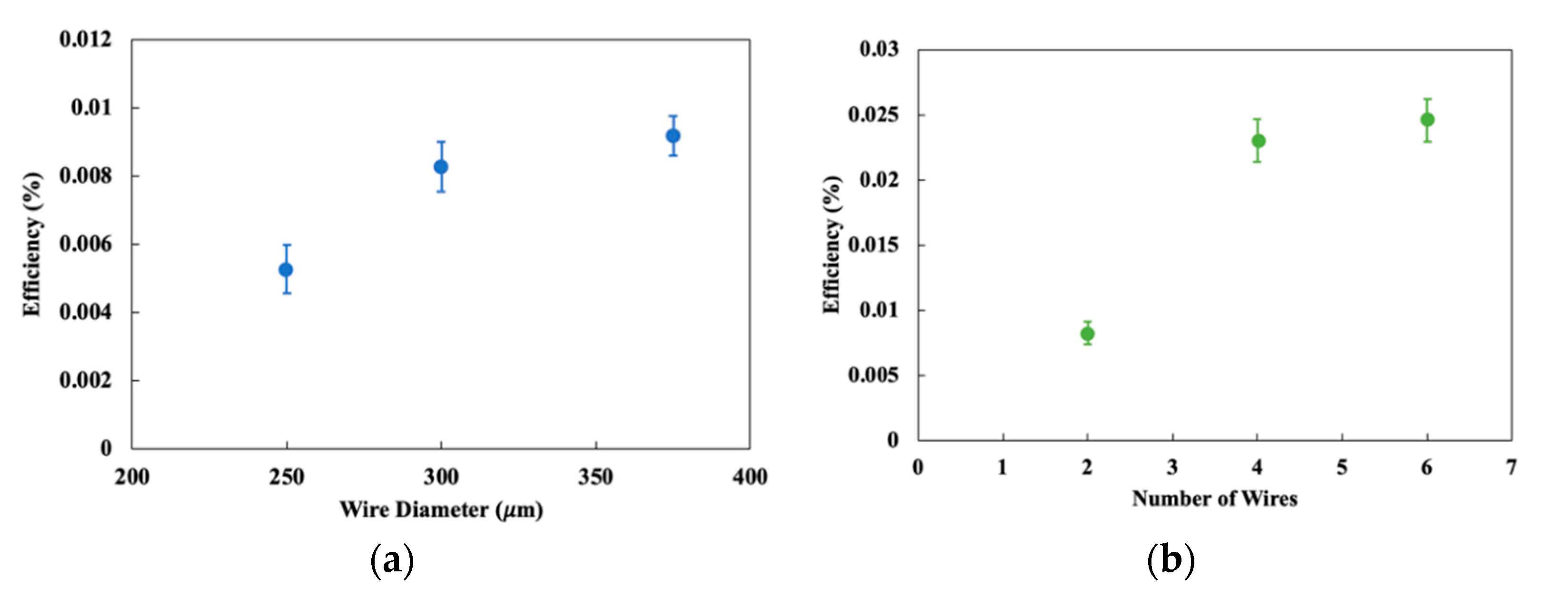
Measurements of energy efficiency were performed on with 250 μm, 300 μm, and 375 μm diameter wires actuators with 2 wires and with 300 μm wire diameter for actuators with 2, 4, or 6 wires. In all cases, the power supply was set to current control at 3.5 A. Each actuator was tested at multiple locations along the cantilevered beam. Sample results are shown in Table 2, where consistent mechanical work results are computed for differing placements, a, along the beam for an actuator with 2 wires and 300 μm diameter.
Efficiencies for the 2-wire design as a function of wire diameter and the multiple wire design with 300 μm SMA wires are shown in Figure 11a,b, respectively. These plots present the average results over 20 tests per design and with a range of one standard deviation. The overarching result shown in the figures is that the SMA actuators are highly inefficient, at least within the confines of the testing procedure. The low efficiency arises because the SMA wires are operated in a flexural rather than contractile mode. Previous experiments [33] support the magnitude of efficiencies and also suggest that other modes of actuation would produce higher efficiencies.
As implemented by [28], the SMA wires are heated by a constant current with the intent of achieving the austenitic transition as quickly as possible, hence maximizing “walking” speed. Higher mechanical efficiencies may be achieved by a scheme were Joule heating power is regulated to affect the temperature needed for the microstructural transformation, but no more. It is worth noting that a limiting efficiency may be calculated from the measured mechanical work and the thermal/electrical energy needed to rise the wire temperature from Martensite to Austenite.
As postulated in the mechanical analysis, greater mechanical forces are developed in larger diameter wires, due to the nonlinear relationship between imparted bending strain and plastic strain energy. Figure 11a tends to support this hypothesis, with efficiency increasing with increasing wire diameter, mirroring the blocking force data seen in Figure 9. Plastic strain energy is functionally proportional to d3 while the thermal/electrical energy will be dependent on wire cross sectional area, hence d2, where d is the diameter of the wire. It is noted that the increase in efficiency plateaus at higher wire diameters, which represents a maximum efficiency for this actuator under the prescribed conditions. The magnitudes of the efficiencies are notably low due to the relatively significant amount of thermal energy required to actuate the wires. This is consistent in magnitude with similar mechanical work-to-thermal energy results with other soft limb actuators SMA wires [34].
Figure 11b shows that for multiple wires, the efficiency increases monotonically with an increase in the number of wires. Since the wires heat up at the same rate for a given energy input, the greater mechanical work output causes the work-to-energy efficiency ratio to increase in direct proportionality to the number of wires. Similar to the finding that efficiency plateaus to a maximum for increasing wire diameters, a corresponding effect is seen for multiple wires. This, paired with the analysis for wire diameters, shows that increasing wire diameter and number of wires will increase the efficiency to a certain extent.
5. Conclusions
Analytical and numerical analysis along with empirical testing were conducted to explore the design space around sizing and number of SMA wires in a highly dynamic soft actuator for soft robots. The finite element and analytical analyses illustrate the influence of wire sizes and wire count on the thermal and mechanical properties of the actuator. Experimental measurements examine force generation and electrical-to-mechanical energy conversion efficiencies for different designs. These tests showed that blocking forces can reach ~0.25 N for a 2-wire design and that electrical-to-mechanical energy conversion efficiencies can be improved by increasing wire diameter and wire count.
The primary findings from this study include the observation that faster cooling, hence faster actuation times, occur with smaller diameter wires that are suitably distanced from one another. These benefits are due to lower thermal mass and minimization of mutual wire heating. Conversely, the study identified the benefit of larger wire diameters to mechanical actuation force. Mechanistically, actuation is dependent on plastic deformation and, for a given radius of curvature, the presence and magnitude of plastic deformation will be enhanced by larger wire diameter. While this study focused on a specific implementation of SMA wires in a soft actuator, the findings presented can be used to guide other designs of SMA-based soft actuators.
Author Contributions
Conceptualization, R.D. and Z.P.; methodology, R.D., Z.P., and C.M.; software, R.D.; validation, R.D., Z.P., and C.M.; formal analysis, R.D.; investigation, R.D.; resources, R.D., Z.P., and C.M.; data curation, R.D.; writing—original draft preparation, R.D.; writing—review and editing, Z.P. and C.M.; visualization, R.D.; supervision, Z.P. and C.M.; project administration, C.M.; funding acquisition, R.D and C.M. All authors have read and agreed to the published version of the manuscript.
Funding
This research was funded by the Office of Naval Research (ONR), grant number N00014-17-1-1063 (PM: Dr. Tom McKenna) and the Carnegie Mellon Summer Undergraduate Research Fellowship (SURF) program.
Institutional Review Board Statement
Not applicable.
Informed Consent Statement
Not applicable.
Data Availability Statement
The data presented in this study are available on request from the corresponding author.
Conflicts of Interest
The authors declare no conflict of interest.
Appendix A
Figure A1.
Configurations for multiple wire arrangements. (a) 2-wire configuration; (b) 4-wire configuration; (c) 6-wire configuration.
Figure A1.
Configurations for multiple wire arrangements. (a) 2-wire configuration; (b) 4-wire configuration; (c) 6-wire configuration.

References
- Majidi, C. Soft Robotics: A Perspective–Current Trends and Prospects for the Future. Soft Rob. 2014, 1, 5–11. [Google Scholar] [CrossRef]
- Kim, S.; Laschi, C.; Trimmer, B. Soft Robotics: A Bioinspired Evolution in Robotics. Trends Biotechnol. 2013, 31, 287–294. [Google Scholar] [CrossRef] [PubMed]
- Rus, D.; Tolley, M. Design, Fabrication and Control of Soft Robots. Nature 2015, 521, 467–475. [Google Scholar] [CrossRef] [Green Version]
- Trivedi, D.; Rahn, C.D.; Kier, W.M.; Walker, I.D. Soft Robotics: Biological Inspiration, State of the Art, and Future Research. Appl. Bionics Biomech. 2008, 5, 99–117. [Google Scholar] [CrossRef]
- Laschi, C.; Mazzolai, B.; Cianchetti, M. Soft Robotics: Technologies and Systems Pushing the Boundaries of Robot Abilities. Sci. Rob. 2016, 1, 1–11. [Google Scholar] [CrossRef] [Green Version]
- Miriyev, A. A Focus on Soft Actuation. Actuators 2019, 8, 74. [Google Scholar] [CrossRef] [Green Version]
- de Payrebrune, K.M.; O’Reilly, O.M. On Constitutive Relations for a Rod-Based Model of a Pneu-Net Bending Actuator. Extrem. Mech. Lett. 2016, 8, 38–46. [Google Scholar] [CrossRef] [Green Version]
- Rich, S.I.; Wood, R.J.; Majidi, C. Untethered Soft Robotics. Nat. Electron. 2018, 1, 102–112. [Google Scholar] [CrossRef]
- Tolley, M.T.; Shepherd, R.F.; Mosadegh, B.; Galloway, K.C.; Wehner, M.; Karpelson, M.; Wood, R.J.; Whitesides, G.M. A Resilient, Untethered Soft Robot. Soft Robot. 2014, 1, 213–223. [Google Scholar] [CrossRef]
- Youn, J.-H.; Jeong, S.M.; Hwang, G.; Kim, H.; Hyeon, K.; Park, J.; Kyung, K.-U. Dielectric Elastomer Actuator for Soft Robotics Applications and Challenges. Appl. Sci. 2020, 10, 640. [Google Scholar] [CrossRef] [Green Version]
- Derby, S.; Sreekumar, M.; Nagarajan, T.; Singaperumal, M.; Zoppi, M.; Molfino, R. Critical Review of Current Trends in Shape Memory Alloy Actuators for Intelligent Robots. Ind. Robot. Int. J. 2007, 34, 285–294. [Google Scholar] [CrossRef]
- Suman, A.; Fabbri, E.; Fortini, A.; Merlin, M.; Pinelli, M. On the Design Strategies for SMA-Based Morphing Actuators: State of the Art and Common Practices Applied to a Fascinating Case Study. Proc. Inst. Mech. Eng. Part G J. Aerosp. Eng. 2020, 234, 2114–2130. [Google Scholar] [CrossRef]
- Bovesecchi, G.; Corasaniti, S.; Costanza, G.; Piferi, F.P.; Tata, M.E. Deployment of Solar Sails by Joule Effect: Thermal Analysis and Experimental Results. Aerospace 2020, 7, 180. [Google Scholar] [CrossRef]
- Rodrigue, H.; Wang, W.; Han, M.W.; Kim, T.J.; Ahn, S.H. An Overview of Shape Memory Alloy-Coupled Actuators and Robots. Soft Robot. 2017, 4, 3–15. [Google Scholar] [CrossRef] [PubMed]
- El-Atab, N.; Mishra, R.B.; Al-Modaf, F.; Joharji, L.; Alsharif, A.A.; Alamoudi, H.; Diaz, M.; Qaiser, N.; Hussain, M.M. Soft Actuators for Soft Robotic Applications: A Review. Adv. Intell. Syst. 2020, 2, 2000128. [Google Scholar] [CrossRef]
- Huang, X.; Ford, M.; Patterson, Z.J.; Zarepoor, M.; Pan, C.; Majidi, C. Shape Memory Materials for Electrically-Powered Soft Machines. J. Mater. Chem. B 2020, 8, 4539–4551. [Google Scholar] [CrossRef] [PubMed]
- Wang, J.; Gu, X.; Xu, Y.; Zhu, J.; Zhang, W. Thermomechanical Modeling of Nonlinear Internal Hysteresis Due to Incomplete Phase Transformation in Pseudoelastic Shape Memory Alloys. Nonlinear Dyn. 2021, 103, 1393–1414. [Google Scholar] [CrossRef]
- Islam, A.B.M.R.; Karadoğan, E. Analysis of One-Dimensional Ivshin–Pence Shape Memory Alloy Constitutive Model for Sensitivity and Uncertainty. Materials 2020, 13, 1482. [Google Scholar] [CrossRef] [PubMed] [Green Version]
- Mohd, J.; Leary, M.; Subic, A.; Gibson, M.A. A Review of Shape Memory Alloy Research, Applications and Opportunities. Mater. Des. 2014, 56, 1078–1113. [Google Scholar] [CrossRef]
- Lee, J.H.; Chung, Y.S.; Rodrigue, H. Long Shape Memory Alloy Tendon-Based Soft Robotic Actuators and Implementation as a Soft Gripper. Sci. Rep. 2019, 9, 1–12. [Google Scholar] [CrossRef]
- Wang, Z.; Hang, G.; Li, J.; Wang, Y.; Xiao, K. A Micro-Robot Fish with Embedded SMA Wire Actuated Flexible Biomimetic Fin. Sens. Actuators A Phys. 2008, 144, 354–360. [Google Scholar] [CrossRef]
- Patterson, Z.J.; Sabelhaus, A.P.; Chin, K.; Hellebrekers, T.; Majidi, C. An Untethered Brittle Star-Inspired Soft Robot for Closed-Loop Underwater Locomotion. In Proceedings of the 2020 IEEE/RSJ International Conference on Intelligent Robots and Systems (IROS), Las Vegas, NV, USA, 24 October–24 January 2021; pp. 8758–8764. [Google Scholar]
- Kim, H.S.; Heo, J.K.; Choi, I.G.; Ahn, S.H.; Chu, W.S. Shape Memory Alloy Driven Undulatory Locomotion of Soft Biomimetic Ray Robot. Bioinspiration Biomim. 2021, accepted. [Google Scholar] [CrossRef]
- Lin, H.-T.; Leisk, G.G.; Trimmer, B. GoQBot: A Caterpillar-Inspired Soft-Bodied Rolling Robot. Bioinspiration Biomim. 2011, 6, 026007. [Google Scholar] [CrossRef] [PubMed]
- Goldberg, N.N.; Huang, X.; Majidi, C.; Novelia, A.; O’Reilly, O.M.; Paley, D.A.; Scott, W.L. On Planar Discrete Elastic Rod Models for the Locomotion of Soft Robots. Soft Robot. 2019, 6, 595–610. [Google Scholar] [CrossRef]
- Seok, S.; Onal, C.D.; Cho, K.J.; Wood, R.J.; Rus, D.; Kim, S. Meshworm: A Peristaltic Soft Robot with Antagonistic Nickel Titanium Coil Actuators. IEEE/ASME Trans. Mechatron. 2012, 18, 1485–1497. [Google Scholar] [CrossRef]
- Lohse, F.; Wende, C.; Klass, K.D.; Hickmann, R.; Häntzsche, E.; Bollengier, Q.; Ashir, M.; Pöschel, R.; Bolk, N.; Trümper, W.; et al. Bio-inspired Semi-flexible Joint Based on Fibre-reinforced Composites with Shape Memory Alloys. J. Intell. Mater. Syst. Struct. 2021, 32, 462–472. [Google Scholar] [CrossRef]
- Huang, X.; Kumar, K.; Jawed, M.K.; Nasab, A.M.; Ye, Z.; Shan, W.; Majidi, C. Highly Dynamic Shape Memory Alloy Actuator for Fast Moving Soft Robots. Adv. Mater. Technol. 2019, 4, 1800540. [Google Scholar] [CrossRef]
- Mao, S.; Dong, E.; Jin, H.; Xu, M.; Zhang, S.; Yang, J.; Low, K.H. Gait Study and Pattern Generation of a Starfish-like Soft Robot with Flexible Rays Actuated by SMAs. J. Bionic Eng. 2014, 11, 400–411. [Google Scholar] [CrossRef]
- Bartlett, M.D.; Kazem, N.; Powell-Palm, M.J.; Huang, X.; Sun, W.; Malen, J.A.; Majidi, C. High Thermal Conductivity in Soft Elastomers with Elongated Liquid Metal Inclusions. Proc. Natl. Acad. Sci. USA 2017, 114, 2143–2148. [Google Scholar] [CrossRef] [PubMed] [Green Version]
- Dynalloy. Available online: http://www.dynalloy.com/tech_data_wire.php (accessed on 12 August 2021).
- Brinson, L.C. One-Dimensional Constitutive Behavior of Shape Memory Alloys: Thermomechanical Derivation with Non-Constant Material Functions and Redefined Martensite Internal Variable. J. Intell. Mater. Syst. Struct. 1993, 4, 229–242. [Google Scholar] [CrossRef]
- Van Humbeeck, J. Non-Medical Applications of Shape Memory Alloys. Mater. Sci. Eng. A 1999, 273–275, 134–148. [Google Scholar] [CrossRef]
- Boyraz, P.; Runge, G.; Raatz, A. An Overview of Novel Actuators for Soft Robotics. Actuators 2018, 7, 48. [Google Scholar] [CrossRef] [Green Version]
Figure 1.
Construction process for each actuator. (a) Apply a 0.2 mm thick layer of silicone (Ecoflex 30) on top of the 55 × 22 × 0.5 mm thermally conductive elastic tape using a thin film applicator; (b) Place the SMA wire in a U-shape on the half-cured silicone and apply a 0.4 mm thick layer of silicone (Ecoflex 30) on top; (c) Prestretch the 70 × 37 × 0.5 mm thermally conductive elastic tape and bond it on top of the rest of the layers; (d) When the silicone (Ecoflex 30) is fully cured, cut out the actuator.

Figure 2.
Cross section of the geometry studied in the transient thermal analysis.
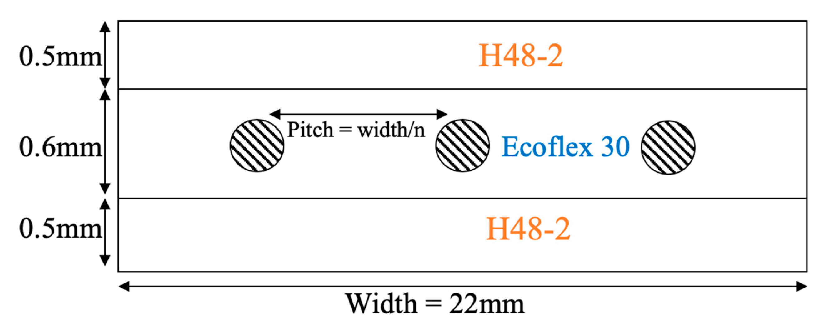
Figure 3.
Transient thermal finite element analysis results after 1 s. (a) Colormaps for 25-wire configuration (top) and 2-wire configuration (bottom); (b) Midplane temperature distribution along width of actuator for 2-wire and 25-wire configurations.
Figure 3.
Transient thermal finite element analysis results after 1 s. (a) Colormaps for 25-wire configuration (top) and 2-wire configuration (bottom); (b) Midplane temperature distribution along width of actuator for 2-wire and 25-wire configurations.
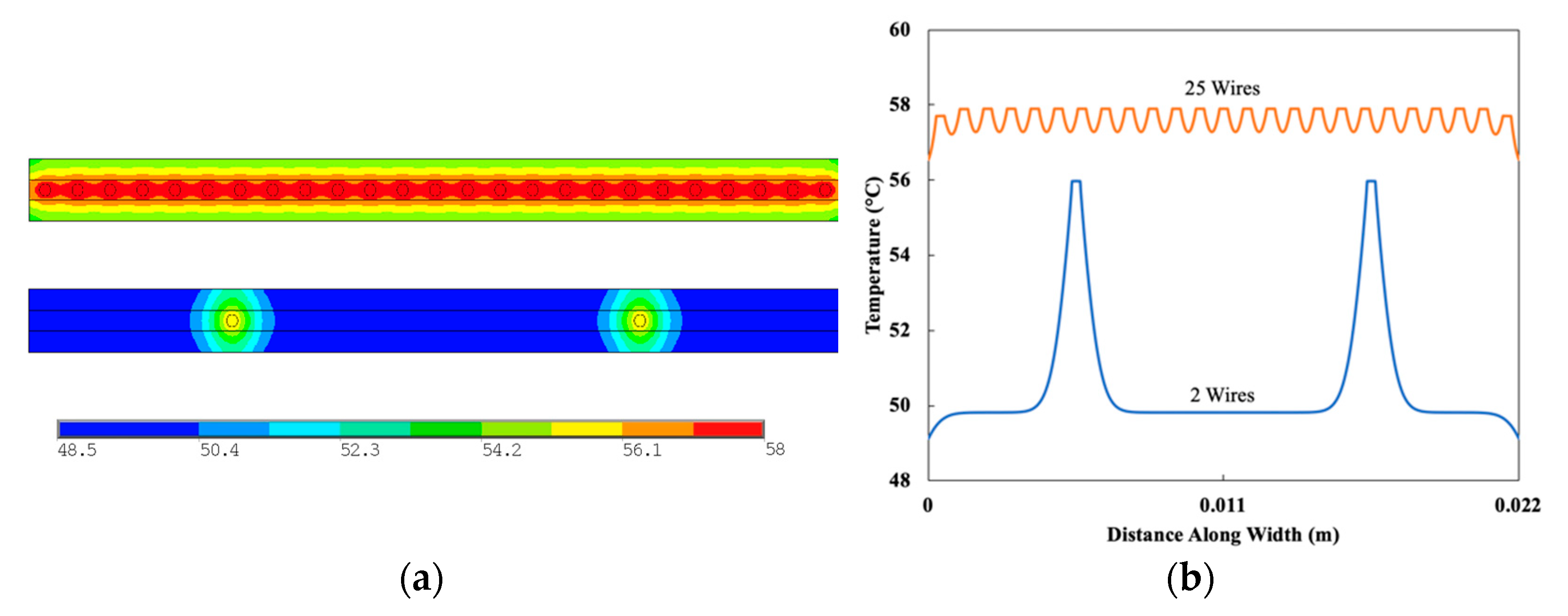
Figure 4.
Transient thermal analysis results for varying wire diameters. (a) Selected transient maximum temperature distributions for varying wire diameters; (b) Time for each wire diameter size to reach 55 °C.
Figure 4.
Transient thermal analysis results for varying wire diameters. (a) Selected transient maximum temperature distributions for varying wire diameters; (b) Time for each wire diameter size to reach 55 °C.
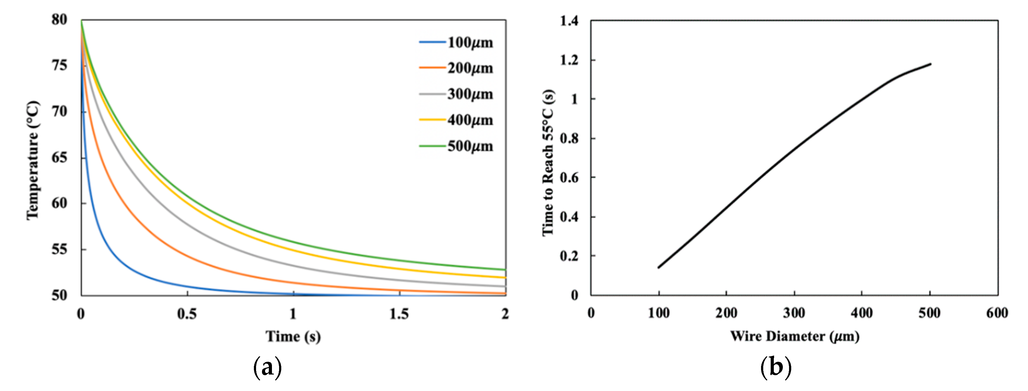
Figure 5.
Results of transient thermal analysis for varying number of wires. (a) Maximum temperature distribution for varying numbers of wires after 2 s; (b) Selected transient maximum temperature distributions for varying numbers of wires.
Figure 5.
Results of transient thermal analysis for varying number of wires. (a) Maximum temperature distribution for varying numbers of wires after 2 s; (b) Selected transient maximum temperature distributions for varying numbers of wires.
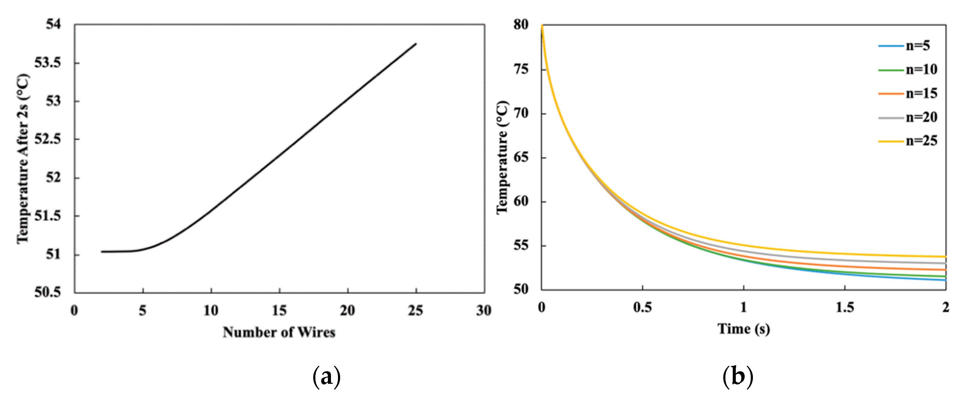
Figure 6.
Stress–strain model for SMA wires at different temperatures.
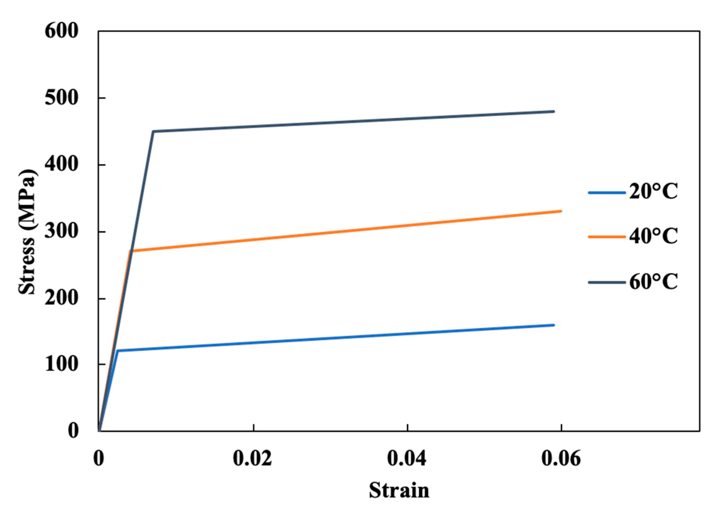
Figure 7.
(a) Internal moment within an actuator for varying radii of curvature; (b) Stress distribution and; (c) Strain distribution for 400 μm diameter wire after bent to a radius of curvature of 1/60 m.
Figure 7.
(a) Internal moment within an actuator for varying radii of curvature; (b) Stress distribution and; (c) Strain distribution for 400 μm diameter wire after bent to a radius of curvature of 1/60 m.

Figure 8.
Blocking force test schematic.
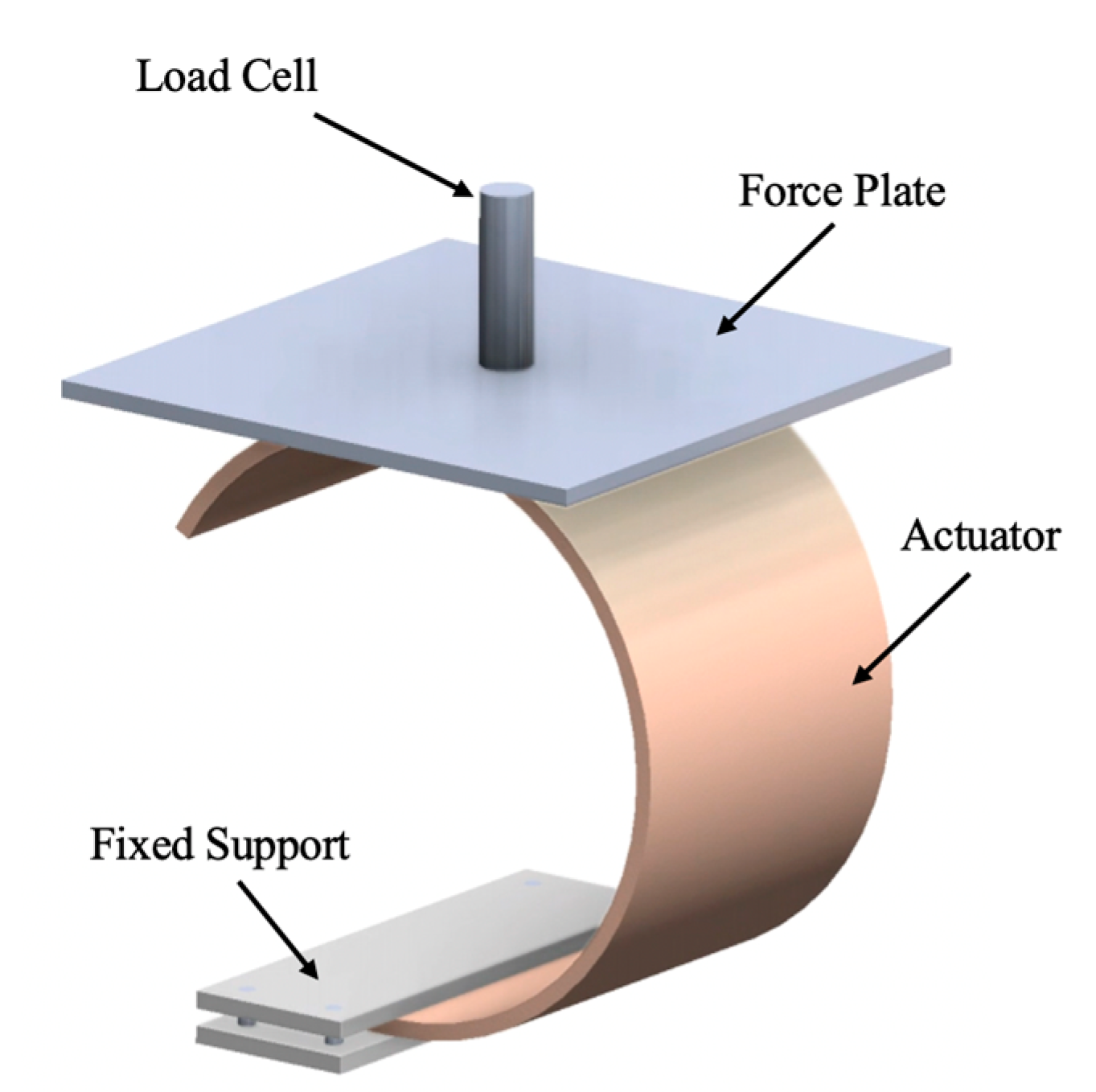
Figure 9.
Blocking force test results with regions where wires are predicted to undergo pure elastic or elasto–plastic deformation.
Figure 9.
Blocking force test results with regions where wires are predicted to undergo pure elastic or elasto–plastic deformation.

Figure 10.
Efficiency test setup. (a) Beam rig schematic; (b) schematic of test setup with connections shown; (c) enlarged portion of (b) to show sample position of actuator along cantilevered beam.
Figure 10.
Efficiency test setup. (a) Beam rig schematic; (b) schematic of test setup with connections shown; (c) enlarged portion of (b) to show sample position of actuator along cantilevered beam.
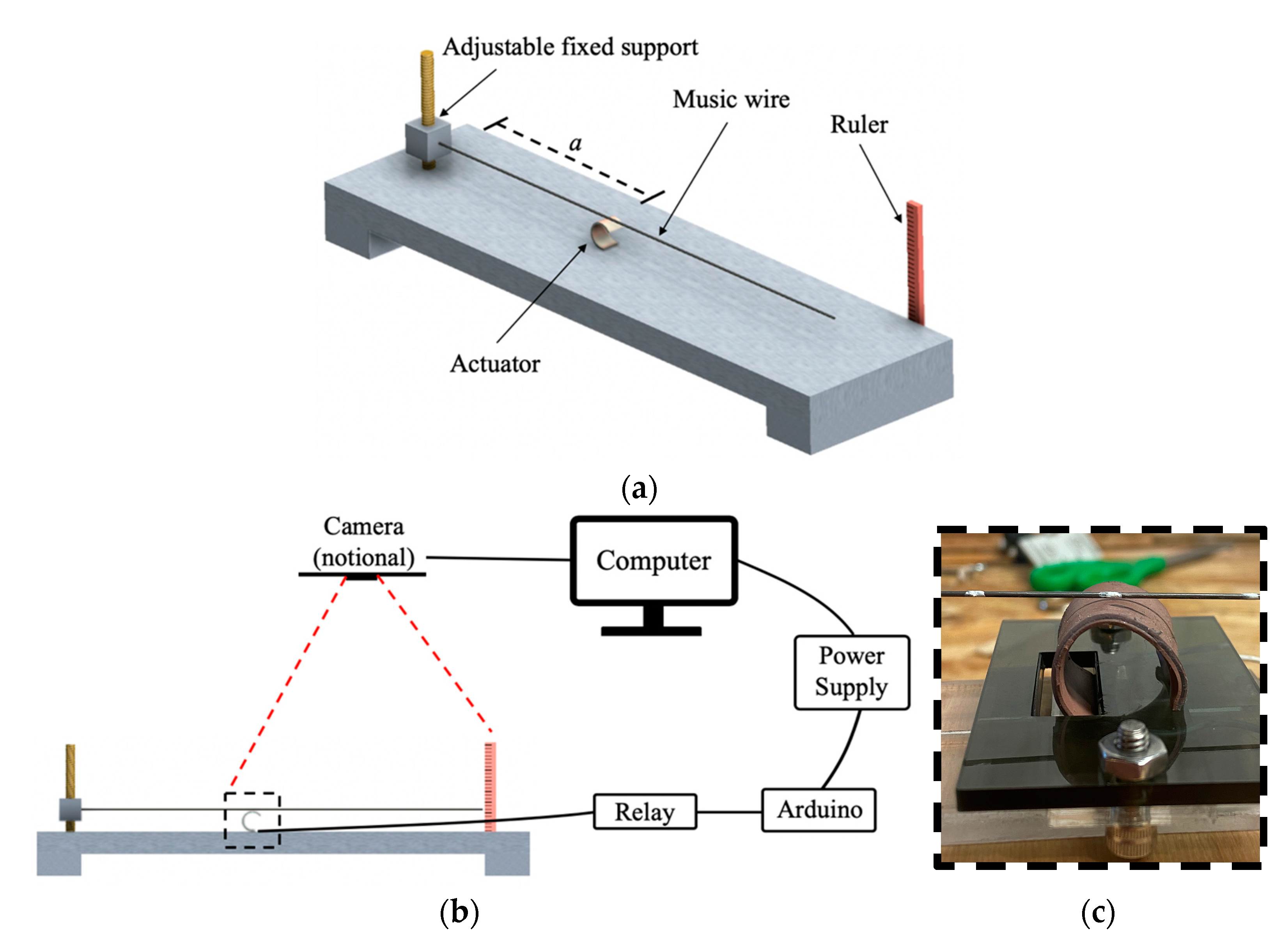
Figure 11.
Efficiency test results. (a) Efficiency test results for varying wire diameters in a 2-wire configuration; (b) efficiency test results for varying numbers of wires with 300 μm diameters.
Figure 11.
Efficiency test results. (a) Efficiency test results for varying wire diameters in a 2-wire configuration; (b) efficiency test results for varying numbers of wires with 300 μm diameters.

Table 1.
Material properties and initial temperature conditions for studied geometry.
| Component | w (kg/m3) | cp (J/kg-K) | k (W/m-K) | T(t = 0) (°C) |
|---|---|---|---|---|
| H48-2 | 2430 | 1000 | 2.2 | 50 |
| Ecoflex 30 | 1070 | 1050 | 0.2 | 50 |
| SMA Wire | 6450 | 837.4 | 18 | 80 |
Table 2.
Sample mechanical work calculations for a test sample.
| Position a from Fixed Support (mm) | (mm) | MW (N*mm) |
|---|---|---|
| 109.2 | 22 | 1.559 |
| 157.5 | 30 | 1.470 |
| 88.9 | 18 | 1.536 |
Publisher’s Note: MDPI stays neutral with regard to jurisdictional claims in published maps and institutional affiliations. |
© 2021 by the authors. Licensee MDPI, Basel, Switzerland. This article is an open access article distributed under the terms and conditions of the Creative Commons Attribution (CC BY) license (https://creativecommons.org/licenses/by/4.0/).
Share and Cite
MDPI and ACS Style
Dauksher, R.; Patterson, Z.; Majidi, C. Characterization and Analysis of a Flexural Shape Memory Alloy Actuator. Actuators 2021, 10, 202. https://doi.org/10.3390/act10080202
AMA Style
Dauksher R, Patterson Z, Majidi C. Characterization and Analysis of a Flexural Shape Memory Alloy Actuator. Actuators. 2021; 10(8):202. https://doi.org/10.3390/act10080202
Chicago/Turabian StyleDauksher, Richard, Zachary Patterson, and Carmel Majidi. 2021. "Characterization and Analysis of a Flexural Shape Memory Alloy Actuator" Actuators 10, no. 8: 202. https://doi.org/10.3390/act10080202
Note that from the first issue of 2016, this journal uses article numbers instead of page numbers. See further details here.