
A Review on the Development of Pneumatic Artificial Muscle Actuators: Force Model and Application

1
Terrestrial Robotics Engineering and Controls (TREC) Laboratory, Virginia Tech, Blacksburg, VA 24060, USA
2
Department of Mechanical Engineering, Indian Institute of Technology Guwahati, Assam 781039, India
*
Author to whom correspondence should be addressed.
Actuators 2022, 11(10), 288; https://doi.org/10.3390/act11100288
Submission received: 21 September 2022
/
Revised: 2 October 2022
/
Accepted: 5 October 2022
/
Published: 9 October 2022
(This article belongs to the Special Issue Pneumatic Actuators for Robotics and Automation)
Abstract
:Pneumatic artificial muscles (PAMs) are soft and flexible linear pneumatic actuators which produce human muscle like actuation. Due to these properties, the muscle actuators have an adaptable compliance for various robotic platforms as well as medical applications. While a variety of possible actuation schemes are present, there is still a need for the development of a soft actuator that is very light-weight, compact, and flexible with high power-to-weight ratio. To achieve this, the development of the PAM actuators has become an interesting topic for many researchers. In this review, the development of the different kinds of PAM available to date are presented along with manufacturing process and the operating principle. The various force models for artificial muscle presented in the literature are broadly reviewed with the constraints. Furthermore, the applications of PAM are included and classified based on the fields of biorobotics, medicine, and industry, along with advanced medical instrumentation. Finally, the needful improvements in terms of the dynamics of the muscle are discussed for the precise control of the PAMs as per the requirements for the applications. This review will be helpful for researchers working in the field of robotics and for designers to develop new type of artificial muscle depending on the applications.
1. Introduction
The development of robotic systems is becoming increasingly prevalent today, with possible applications including personal or mobile robots working alongside humans, as well as exoskeletons worn to restore or improve human abilities. Due to their flexibility and soft nature, Pneumatic artificial muscles (PAMs) have evolved as the possible actuation strategy among the other available actuators in the market over the last 30 years [1]. The field of artificial muscle actuator is highly interdisciplinary and attracts many researchers from the fields of mechanical engineering, material science, electrical engineering, biology, and physics. PAMs are simple mechanical actuators that consist of an elastomeric bladder within a braided mesh sleeve with two end-fittings to seal both the ends of the muscle. Upon pressurization of the bladder by air, the actuator either contracts or extends axially, with the direction of motion dependent on the orientation of the braided sleeve fibers. The contractile PAMs are able to produce higher forces than extensile PAMs and are less prone to buckling; hence, the contractile PAMs are more commonly utilized, and are also known as the contractile actuator.
There are different types of conventional actuating mechanisms such as: electric motors, hydraulic actuators, pneumatic pistons, and shape memory alloys (SMA), along with the flexible actuators used in various applications. However, the use of artificial muscles is more beneficial in comparison to the other actuation mechanism due to their following advantages [2,3,4,5,6,7]:
- PAMs are lightweight and produce a strong force, which provides high power-to-weight ratio for the applications.
- PAMs provide flexibility and compliance for the applications in a pressurized or unpressurized condition.
- PAMs deliver a safe and compatible interaction with the human environment only by controlling the volume flow rate of operating air into the muscle.
- Simple PAMs can be fabricated from inexpensive materials, which reduce the overall manufacturing cost.
- PAMs provide the linear contractile motion with a monotonically decreasing load-contraction relation like the skeletal muscle, which can control joint compliance.
- PAMs exhibit the nature of essential compliance for installation for providing required power, and the values of speed along with force are in the range of what is needed.
- Because of the direct connection, replacement of a defective PAM with a new one can be done easily and swiftly by uncoupling the muscle along with pneumatic tubing.
- Due to the intrinsic and adjustable compliance, PAMs can be made to have a soft touch and, consequently, are well-suited for safe human–robot interaction.
Due to these benefits, a number of groups have investigated the design geometries and fabrication methods of different types of artificial muscle actuators. The physics behind the operation of PAMs is the same as that of human muscle as it converts the pneumatic power to pulling force. The compressibility of the air plays a significant role in the artificial muscles for the unpredictable impact. Various types of conventional PAMs, as shown in Figure 1, have been developed depending on the different operating principles, applications, and design concepts [6]. These can be classified in the literature into four major types, such as braided muscles, pleated muscles, netted muscles, and embedded muscles. For various medical applications, high torques are required at low to moderate speeds. Therefore, the proper selection of the actuator is the crucial part to avoid undesired phenomena like backlash, friction, and extra inertia to the structure. It may lead to a more complicated design with heavy construction, which is not acceptable by the user. Hence, there is a need to make it lightweight and compact to actuate the body’s compliant joints in a real environment. In response to this, Kalita [7] presented theoretical and experimental studies to evaluate the safe operating range of PAM for different conditions with the nonlinear characteristics present in the muscle actuator. For the actuation of these devices, electrical motors like DC motors, AC motors, stepper motors, and linear motors are commonly used, through which high acceleration and positional accuracy can be achieved. However, for human–robot interaction, the high rigidity of the joints in these robots will be very dangerous for the operator due to a large amount of weight of the electric motors. The power-to-weight ratios for the electric actuators are in the order of magnitude of 100 W/kg with higher peak values and the range of the output torques within 1–10 Nm per kilogram [8,9,10]. To achieve high torques at a low speed, some gearing attachment or high-performance motors has to be developed. Raab and Isermann [9] mentioned that hydraulic actuators with a power-to-weight ratio of 2000 W/kg can achieve high torques at low speeds. Though there is a chance of leakage in the energy source due to high operating pressure, it can be directly connected to the robot joints. With the use of the servo-valve control, this kind of actuation can acquire the necessary compliance characteristics.
Pneumatic cylinders are the most commonly used pneumatic actuators with power-to-weight ratios of 400 W/kg, which can be operated with moderate speeds [9]. The inherent compliance characteristics are present in the pneumatic actuators due to the compressibility of the air pressure; therefore, PAM has been used as an alternative pneumatic actuator in the medical applications to achieve better power-to-weight ratio than the pneumatic cylinder. The muscle actuator is operated with the help of the pressurized air through a core deformable membrane, and the required motion can be obtained. Due to the use of the viscoelastic materials in most of the available PAM, it is lightweight in nature, and the deformation is based on the material elongation. The power-to-weight ratio of these kinds of actuators is normally higher than 1 kW/kg [11]. Other new particular actuators like shape memory alloys (SMA) and polymeric actuators have been used in various applications, but these actuators are very much specific-application-oriented, and their speeds of operation are also very low [10,12].
Table 1 presents a comparison of the maximum strain (stroke divided by resting length), actuation stress (force divided by cross-sectional area), and specific work (work divided by mass) of several types of actuators, which is inspired by the work of Woods [13]. PAMs combine large usable strains with significant actuation stresses to yield a higher ratio of work to mass (i.e., specific action) than several other actuation technologies such as electromechanical actuators, solenoids, and piezoelectric or magnetostrictive materials. Hence, due to the advantages of PAM over the other actuators, these muscle actuators are the most suitable for various industrial [6] and medical [14,15] applications. In addition to these performance advantages, PAMs boast a variety of structural advantages as well. PAMs are very durable and have long fatigue life, having demonstrated only small wear and tear signs after 120 million actuation cycles [16].
The PAM actuators significantly gained importance in the field of biomedical as well as industrial applications including micro/nano scales in recent years due to the above-mentioned advantages of the PAM over the other available actuators. However, the effectiveness and safety of the applications depend on the nature of PAMs based on the material properties, dimensions, and operating conditions. To understand these properties of the PAMs, a comprehensive systematic review is demanded on the available PAM actuators based on the design types and applications along with the force models utilized by the muscle actuators. The scope of this state of the art is to address the following research questions about the PAM actuators: (1) What are the basic operating principles of PAM actuators? (2) How are the PAMs advantageous over the other actuators? (3) What types of PAMs are available in the market or developed by research? (4) How have the muscles been modeled for understanding the muscle force? (5) What should be the design criteria for efficient PAMs? (6) What are the different applications found in the fields of biorobotics, medicine, and industry? (7) What are the possible developments required in the PAM actuators for future prospects?
Therefore, to address these impending questions, a systematic review is presented in this work to provide a brief idea on the interesting and trending topic of PAM actuators. In the next section, the basic concept and operating principle of the PAM actuators are discussed followed by the different kinds of muscle actuators available in the literature as well as in the market. Thereafter, the muscle force models developed by many researchers and designers are investigated along with the different kinds of applications based on the fields included. Finally, a discussion on the design criteria, research gap, and challenges along with possible directions for improvement in the development of muscle actuators are presented.
2. Concept and Operation
Pneumatic Artificial Muscle (PAM) is a contractile and linear motion actuator operated by the air pressure. The main two parts of most of these kinds of actuators are the flexible core and the reinforced closed membrane like shell and diaphragm. Both ends of these muscle actuators are closed with the end fitting (closures, clamps). The core membrane is bulged outward or squeezed due to the supply of the air pressure and through which the mechanical power is transmitted to a load. The core contracts axially apply a pulling force on its load due to the radial expansion or contraction. Therefore, the force (tension, load) and the motion achieved by the PAM actuator are linear and unidirectional. To understand the basic concept and working principle of muscle actuators, an antagonistic arrangement has been developed with the help of a chain-sprocket mechanism and it can be used for testing a wide range of muscle available in the market before use in the actual applications [17]. This contractile operation, which extends upon inflation, differentiates these actuators from the bellows. The PAMs are known with various names in the literature as: Pneumatic Muscle Actuator [11], Fluid Actuator [18], Fluid-Driven Tension Actuator [19], Axially Contractible Actuator [20,21], and Tension Actuator [22,23].
The basic energy source to a PAM is primarily air either forced into it or extracted from it. This creates a pressure difference between the air inside the muscle and its surroundings, through which the PAM can be actuated to obtain the required motion. More energy can be transferred by overpressure as compared to underpressure. Most of the PAMs operate at overpressure with ambient pressure around 100 kPa, though there is possibility to design an underpressure operating muscle [24,25]. Hence, by supplying compressed air into the muscle, the required motion can be obtained to move a load and vice versa by discharging the air pressure.
The basic operations of the PAM can be considered with two examples: (1) under a constant load and with varying gauge pressure, and (2) with a constant gauge pressure and a varying load. Figure 2a, for the first operation, shows a PAM that is fixed at one end with a constant mass (M) hanging from the other side. The pressure difference across the membrane, i.e., its gauge pressure, can be increased from an initial value of zero. At zero gauge pressure, the volume of the membrane is considered to be minimum and its length maximum . Now, the actuator is pressurized to a gauge pressure , which makes the muscle bulge and, at the same time, it develops a pulling force. This force will lift the mass (M) until the equilibrium point where the generated force will equal to the mass weight . In this condition, the volume of the PAM is increased to and its length is contracted to . Further increasing the pressure to , this process will continue until it reaches the maximum allowable gauge pressure . From this kind of operation of the PAM, two basic actuator behavior rules can be noticed, where a PAM shortens by increasing its enclosed volume and it will contract against a constant load if the pneumatic pressure is increased.
The second type operation of PAM under constant gauge pressure is shown in Figure 2b with an example. Here, the gauge pressure is kept at a constant value P with a decrease in the load where the muscle will inflate and shorten. If the load is completely removed, as shown in Figure 2b, the swelling goes to its full extent with the maximum volume of the PAM, . In this situation, the length of the muscle will reach the minimum value and the pulling force will drop to zero. PAM will not be able to contract beyond this point and behaves as a bellows at a shorter length, which generates a pushing instead of pulling force. This means that a PAM will shorten at a constant pressure if its load is decreased and its contraction has an upper limit at which it develops no force along with its enclosed volume is maximal. From these two examples of PAM operations, it can be concluded that PAM has an equilibrium length for each pair of pressure and load. This characteristic is in total contrast to the operation of a pneumatic cylinder where the developed actuation force only depends on the pressure and the piston surface area so that, at constant pressure, it will be consistent regardless of the displacement [4]. In the next section, the design of four classifications of PAMs are explained along with some advanced pneumatic muscle actuators.
3. Classification of Pneumatic Artificial Muscle
According to Marcinčin and Palko [24], in 1930, various muscle-like actuators had been developed by a Russian inventor named S. Garasiev. These actuators can be classified based on the design and operation characteristics, such as: (1) pneumatic or hydraulic operation, (2) overpressure or underpressure operation, (3) braided/netted or embedded membrane, and (4) stretching membrane or rearranging membrane. Though the hydraulic operation is considered only for completeness sake, the main feature of the artificial muscles is their inflation and deformation. Due to this feature, the flexibility is needed in the muscles for which the material strength along with the pressure difference should be limited. This makes the PAM an attractive and advantageous actuator over the other hydraulic actuator. The third characteristic mentions the tension carrying element of the muscle, which is a structure either embracing the membrane or embedded in the membrane. The last characteristic describes how the membrane inflates where it can be able to expand radially; either the membrane material has to stretch, or the radial section has to change by rearranging the membrane’s surface. In the case of pure rearranging, the total membrane surface is constant regardless of contraction and volume. This allows for greater tension to be developed as no energy is put into stretching membrane material. Based on these characteristics, further, this review will focus on four types of PAM, namely, the braided muscles, which are the most frequently used, the pleated PAM, the netted muscle, and the embedded muscle, which was developed as an improvement with regard to the drawbacks of the braided design.
3.1. Braided Muscle
Braided muscles are composed of a gas-tight elastic tube or bladder surrounded by a braided netting (weave, braid, sleeve), as shown in Figure 3. The braid fibers run helically about the long axis of the muscle at an angle (pitch angle, braid angle, weave angle). The tube is pressurized laterally against the sleeve and the internal pressure inside the tube is restricted by braid fiber tension due to fiber curvature. The fiber tension is incorporated at the endpoints of the braid to balance the external load. Hence, the pressing contact between tube and sleeve is necessary to lift the load, and braided muscles cannot operate at underpressure. The most common braided muscles are the McKibben muscle [2,3,26,27], where both its inner tube and braid connected to fittings at both ends. Another this type of muscle is known as sleeved bladder muscle [28], which has only the braid connected to end fittings and in which the inner tube is an unattached bladder.
The McKibben muscle, as shown in Figure 4, was derived from a patented design by Morin [25], who embedded the fibers into a rubber diaphragm. According to Baldwin [29], it was first introduced by the physician, Joseph L. McKibben, in the 1950s to actuate an orthotic device for polio patients due to the similarity in length–load curves between this artificial muscle and skeletal muscle [30,31]. The general behavior of these muscles with regard to shape, contraction, and tension when inflated will depend on the geometry of the bladder and surrounded braid at unpressurized condition along with the materials used. Usually, these braided muscles have a cylindrical shape because of a cylindrical bladder and a constant pitch angle throughout the braid. The sleeved bladder muscles, patent by Beullens [28], are different from the McKibben type in the design of the inner bladder, where it is not connected to the sleeve, which means that there is no passive spring force is added to muscle tension. The main advantage of this type of PAM is its extreme ease of assembly.
3.2. Pleated Muscle
Pleated muscle actuator was developed by Daerden and Lefeber [32,33], which is shown in Figure 5a. There is no material strain and friction involved in this type of muscle when it is inflated. This is due to the muscle membrane, which consists of the number of pleats in the axial direction and inflates by unfolding the pleats. Furthermore, membrane stresses in the parallel direction (perpendicular to the axis) are kept negligibly small and decrease with increasing the number of folds. Basically, there is no required external energy to inflate the membrane and, due to the absence of friction, no hysteresis is observed. The characteristics of this type of muscle depend on the ratio of full length to minimum diameter, strain behavior of the membrane’s material, contraction rate, and applied pressure. A modified version of the pleated muscle actuator by Terryn et al. [34] is shown in Figure 5b, where the membrane is constructed out of a self-healing polymer.
3.3. Netted Muscle
The main difference between braided and netted muscles is the density of the grid surrounding the membrane, where a mesh with relatively large holes with a braid is tightly woven. Due to this, the membrane is of the stretching kind where the muscle can withstand only low pressures. Therefore, this type of muscle actuator will usually have a diaphragm of the rearranging kind. Figure 6a shows the Yarlott muscle by J. M. Yarlott [18], which includes an elastomeric bladder of a prolate spheroidal shape netted by a series of cords or strands. This actuator takes the spheroid bladder shape in its inflated state, and when elongated, the axial strands straighten out and push the bladder into a shape characterized by a series of ridges and valleys. Figure 6b shows another type of netted muscle, the Robotic Muscle Actuator (ROMAC), which was designed by G. Immega and M. Kukolj in 1986 [20]. ROMAC consists of an articulating polylobe bladder harnessed by a wire netting and closed at either end by fittings [35], where the bladder is made of a sheath that is characterized by its high tensile stiffness, flexibility, and fluid-tightness. The netting or harness is comprised of non-stretchable flexible tension links joining at nodes to form four-sided diamond-shaped apertures in the network. Figure 6c shows the Kukolj muscle by M. Kukolj [21], which is a modification of the standard McKibben muscle. The main difference between the muscles is the sleeve, where the McKibben muscles have a tightly woven braid, and the Kukolj design uses an open-meshed net. In a nonleaded condition, there is a gap between the net and the membrane, which only disappears at a suitably high extending load.
3.4. Embedded Muscle
In embedded muscles, the load-carrying structure of the actuators is embedded in its membrane. The Morin muscle by A. H. Morin [25], consists of a rubber tube embedded by threads of a high tensile stiffness. The threads can be arranged along the actuator’s long axis or in a double helix about that axis, and the fiber material may be used like cotton, rayon, asbestos, or steel. Depending on the working of operating pressure, three designs of Morin muscle have been shown in Figure 7a, namely, an overpressure design as shown in a longitudinal cross-section, an underpressure design, and a concentric membranes design. The Baldwin muscle by H. A. Baldwin [29], based on the design of Morin muscle [25], consists of an elastomeric membrane, a very thin surgical rubber that is embedded by glass filaments in the axial direction. The Under Pressure Artificial Muscle (UPAM) developed by K. Nazarczuk in 1964 at the Warsaw Polytechnic [24], exhibits similar design as the Morin muscle [25]. As gas is sucked out of the membrane it collapses in a non-axisymmetric way, i.e., it is squeezed and flattened in the middle.
The Paynter Knitted Muscle developed by H. M. Paynter [23] has a spherical bladder of elastomeric material that is reinforced by a knitted structure of strong, tough, and flexible fibers. When fully inflated, the muscle takes on the shape of the original bladder and knitting sphere. Figure 7b shows the Paynter Hyperboloid Muscle, which is an alternative design described by H. M. Paynter [19]. The elastomeric membrane of the muscle is made with the neoprene rubber or polyurethane, which takes the shape of a hyperboloid of revolution in its fully elongated state. The membrane is embedded by a sleeve of inextensible, flexible threads of metal wires, cord, polyester fibers, or para-aramid fibers attached to the end fittings. Figure 7c shows the Kleinwachter torsion device by Kleinwachter and Geerk [36], where the inflatable membrane technique can be used in designing a torsional device, which refers to a torsion muscle. The device has a toroid diaphragm embedded with stiffening filaments and attached at its outer edge to a ring-shaped structure along with its inner edge to a shaft.
Along with these classifications of the traditional PAMs, there are more advanced pneumatic muscles designed and developed in the literature [37,38,39,40,41,42,43,44,45,46,47]. An artificial muscle tube has been developed by Nakamura et al. [38], as shown in Figure 8a, in which high-intensity glass fiber had been built into a natural latex rubber tube (Straight fibre type). Kalita and Dwivedy [39,40] fabricated an affordable PAM actuator as compared to the McKibben type using natural silk fibers (Pat and Muga Silk) reinforcement with silicon rubber, which can be easily modified depending on the requirement of the applications. Veale et al. [41] developed the Planar Fluidic Muscles, known as Peano muscles or pouch motors, as shown in Figure 8b, which have the potential to provide the high force and compliance of McKibben muscles with the low threshold pressure of pleated PAMs. Figure 8c shows a Soft Robotic Muscle (SRM) actuator fabricated by Oguntosin and Akindele [42] with the help of silicone rubber using a molding process. Greer et al. [45] designed the series Pneumatic Artificial Muscle (sPAM), as shown in Figure 8d, which is made from a thin rectangular sheet of polyethylene tube that is sealed (heat bonded) on one end so that it inflates. Wirekoh and Park [43] designed the Flat Pneumatic Artificial Muscle (FPAM), as shown in Figure 8e, which is made of a silicon substrate that contains embedded Kevlar fibers.
Further, a modification has been done to the FPAM by integrating with force and position sensors, which resulted in a sensorized, Flat, Pneumatic Artificial Muscle (sFPAM) by Wirekoh et al. [44], as shown in Figure 8f. Han et al. [37] developed a High-Contraction Ratio Pneumatic Artificial Muscle (HCRPAM), as shown in Figure 8g, which consists of three parts viz., an elliptical tube that generates the expansion force, a diamond-shaped band that converts the expansion force of the elliptical tube into the output contraction force, and a two-stage spline that maintains the straight elongation of the elliptical tube. Figure 8h shows the reverse Pneumatic Artificial Muscle (rPAM) by Skorina et al. [46], which consists of silicone rubber that is radially constrained by symmetrical double-helix threading. Yang et al. [47] designed a high-displacement pneumatic artificial muscle, as shown in Figure 8i, which is made of textiles or plastics that can include integrated electronics to sense its pressure and displacement. Depending on the various design of PAMs, the force models considered in the literature have been discussed in the next section to better understand the dynamics and control of the PAM.
4. Force Model of Pneumatic Artificial Muscle
There are many studies available regarding the mathematical modeling of PAMs. The basic component of the modeling is the relation between the pressure and the length of the PAM actuator to the exerted force along its entire axis. The muscle force is primarily considered a function of operating pressure, material properties, and dimensions of the muscle, which play an important role in the PAM’s dynamical behavior. Therefore, the mathematical modeling of PAM is very important in understanding the relationship between the factors for various applications and controlling the overall functioning of the muscle. However, PAM exhibits strong nonlinear force-length characteristics, making it challenging to model and control, as well as to obtain the demanded performance features [33,48]. Kelasidi et al. [49] explained the most common and important mathematical modeling of PAM found in the literature.
4.1. Geometrical Model
There are two geometric models of PAM, which are the most common and widely used, namely, the Chou and Hannaford model [2] and the Tondu and Lopez model [3]. The Chou and Hannaford model [2] is the simplest geometrical model for a static performance of the PAM. With this approach, the PAM has been modeled as a cylinder, as shown in Figure 9, with a length L, thread length b, diameter D, and number of thread turns n. The angle is defined as the angle of the threads with the longitudinal axis. Utilizing the energy conservation principle, the simple geometric force of PAM is calculated as follows, multiplying the gauge pressure P with the change in volume with respect to length [50].
Another widely used geometrical model of PAM is the Tondu and Lopez model [3], which is based on the virtual work theorem. The expression for the contraction force generated by the muscle which is a function of the control pressure and the contraction ratio is written as follows [3,51,52]:
where , , , and is the nominal inner radius, l is the length of the muscle, is the initial nominal length, P is the pressure and is the initial angle between the membrane fibres and the muscle axis. A disadvantage of the model is its design, which is based on the hypothesis of a continuously cylindrical shaped muscle. In contrast, it takes a conic shape at both ends when it contracts. Consequently, the more the muscle contracts, the more its active part decreases.
This phenomenon results in the actual maximum contraction theoretically being smaller than that expected from Equation (2) [53]. Hence, to improve Equation (2), Tondu and Lopez [3] considered an empirical factor k in addition to account for the end deformation of the PAM as follows:
where , and . By inserting the parameter k within the considered static model, the value of the maximum force given at zero contraction is not get affected. This is in concordance with the conducted experiment since the PAM has a cylindrical shape only when its contraction ratio is zero.
4.2. Biomimetic/Biomechanical Model
There is a method of PAM modeling which is popularly known as biomimetic or biomechanical model due to similarities with the biological muscle and try to model in the literature [27]. Basically, PAM is a composite of a rubber mold with embedded structural fibers, which creates a force in the longitudinal direction extending the circumferential direction in pressurized condition. A phenomenological approach is considered by Serres et al. [54,55] to understand the dynamics of PAMs by modeling it with three elements: a spring element, a damping element, and a contractile element in parallel, as shown in Figure 10.
X is the displacement of PAM, M is the mass of moving parts, C is the damping coefficient, is the contractile force coefficient, K is the spring coefficient of PAM, and F is the external load. Further, by taking the Laplace transform and setting the initial conditions to zero, the transfer function of the phenomenological model of PAM is derived as follows [54], where is the desired displacement of the PAM and .
4.3. Empirical Model
PAM with different lengths and diameters can be modeled with the help of simplified empirical models. In this approach, The stretched length is zero when the air pressure inside PAM only the atmospheric pressure, and this length increases when the air pressure also increases [56]. The natural mechanical operation of the PAM and the mechanical spring exhibit similar behavior when a tensile force is being applied to them, as shown in Figure 11. Usually, the stiffness of the spring is fixed and depends on the material properties and geometry of the spring, whereas the stiffness of PAM is variable and also depends on the above properties in addition to the air pressure inside the muscle.
Based on the experimental observation by Wickramatunge and Leephakpreeda [57,58], the pulling force acting on PAM can be modeled as similar to the force acting on a mechanical spring where the stiffness parameter of PAM can also be specified as K. The stiffness parameter K is the function of the operating gauge pressure P and the stretched length of the PAM . The elastic force generated by PAM, is given below.
The stiffness K explicitly has been considered as a second order polynomial of P and which is represented as follows:
where the constant parameters , , and can be found from experimental data by applying the method of least squares. Further, higher degree polynomials can be applied to obtain the desired precision requirement.
In another experimental work by Li et al. [59], the force-contraction quasi-static characterization of the PAM is considered along with a linear least squares fit at each operating pressure. The muscle force is estimated to vary as a linear function of the contraction and operating pressure P as follows.
where , , , , and are the experimental constant parameters which are obtained from the least squares fit. Using this muscle force equation, Kalita and Dwivedy [60] evaluated the safe operating range along with the critical values of the different parameters present in the McKibben type muscle actuator using parametric instability regions and validated by performing experiments.
Along with these, various other novel methods have been proposed in the literature for the analysis of PAM to establish accurate empirical models. A PAM motion caused by a nonlinear force that mainly depends on parameters like pressure and deformation is obtained analytically by applying the optimal parameter identification method. This method has finally been proved and tested on an experimental rig by Sárosi et al. [61] and Palomares et al. [62]. Cullinan et al. [63] and Cveticanin et al. [64] have investigated the steady state position of the mass of the system and the force influenced by the pressure of the PAM mathematically and experimentally. Colbrunn et al. [65] studied the static and dynamic mathematical model for the braided pneumatic actuator. Tóthová et al. [66] used two PAMs for antagonistic motion connected through the chain gear and investigated based on modified Hill’s basic model. Hildebrandt et al. [67] presented a nonlinear cascaded control strategy to move a trolley actuated through pneumatic muscle actuators to follow a reference path. Carneiro et al. [68] used two servo valves for pneumatic force actuation. Tothova et al. [69] discussed the analytical model of muscle force based on the measured values.
In cases of higher positioning requirements and motion in two opposite directions needs, two PAMs in an antagonistic connection are highly preferred, just like in real muscles in the living bodies [61,70,71,72,73]. Šitum and Trslić [73] discussed a nonlinear mathematical model for a PAM pair in an antagonistic arrangement based on an original and unique ball-on-beam system. Liu et al. [74] and Xie et al. [75] used advanced techniques like the modified Prandtl–Ishlinskii (MPI) model to control the inherent hysteresis nonlinearity for the accuracy of trajectory tracking control of PAM. Other advanced force models for the PAM have been mentioned, which are discussed in the literature such as the approximate deducted model using the maximum force of PAM [76], the polynomial function model [77], and the exponential function model [78].
Ashwin and Ghosal [5] presented a discussion on some more different empirical models from the literature and the key equations for the muscle force those are discussed in Table 2. In Table 2, , , and represent length, outer radius, and thickness of the bladder before deformation, respectively, and, after deformation, these change to l, r, and t, respectively. The initial inner radius of the bladder represents by , whereas the initial and final winding angles of the braid are denoted as and , respectively. The symbols N, m, and b represent the number of turns of the braid along the length, number of strands of braid, as well as the length of a single braid strand, respectively. P is the input pressure, F represents the muscle force, and the strain in the bladder along the axial direction is . All other unknown parameters used in the equations are considered to be constant in general.
4.4. Nonlinear Model
A highly nonlinear nature is present in the PAM due to the air compressibility, valve actuation, viscoelastic material properties, and load contraction characteristics due to flexible structure. The other factors like the irregular shape of the rubber bladder geometry [91], elastic energy [83,87,92,93] present in the bladder and braid, and threshold pressure [94] also contribute to the nonlinear characteristics of the PAM. Therefore, to include these nonlinearities, some specific models have been presented in the literature. Kalita and Dwivedy [95,96,97,98] investigated the responses and behaviors of the nonlinear PAMs by adding a cubic nonlinearity to the muscle force Equation (7) for the consideration of nonlinearities present in the muscle actuator. The nonlinear dynamics of a system attached with a PAM is studied under simultaneous resonance condition [95] and principal parametric resonance condition [96]. The fluctuation of operating pressure in the muscle is considered to be a periodically time varying pressure , where and represents the dynamic pressure and static pressure inside the muscle, respectively [95,96]. The governing equation of motion for the system results in a forced and parametrically excited system with cubic nonlinearity due to the nonlinear muscle force as shown below.
The nonlinear dynamics present in the PAMs have been studied by considering a constant pressure inside the muscle, which resulted in harmonically excited system in [97] and a system under hard excitation in [98]. In the experimental work [97], the nonlinear parameters in the muscle force are obtained by performing experiments for the system under simple resonance condition with the help of a developed antagonistic experimental setup. The chaotic behaviors present in the muscle actuator are investigated with the system under hard excitation where the forcing amplitude is higher than the coefficient of the linear term and subjected to super- and sub-harmonic resonance conditions [98]. As the superposition rule is not applicable to nonlinear systems, the responses obtained in one resonance condition may not be useful for other resonance conditions. Hence, dynamic modeling and analysis are very much essential, particularly for the systems attached with PAM due to their high nonlinear nature.
Determining accurate values for constants in nonlinear models often requires precise experimentation. Therefore, by considering the material properties precisely along with an extensive computation, the nonlinear material modeling may provide better accuracy. A nonlinear Mooney–Rivlin material [99,100] is considered for the elastic properties of the bladder, and the stress components from strain energy density functions are used in the force balance equations. Considering this material, Kothera et al. [93] derived the following muscle force expression by using an energy balance method
where is Young’s modulus and , , and are the stretch ratios of the braided Mooney–Rivlin material [99,100]. Later, this model is used by Woods et al. [101] for generating large trailing edge flap in a helicopter with the help of PAM. Wang et al. [87] described a static model of PAM by using Mooney–Rivlin material where Hoop force and axial force acting on bladder during inflation are found analytically in terms of and P. Thus, from the static force balance equations from braid, the muscle force can be obtained as follows.
Some other nonlinear materials, such as neo-Hookean material [102], are also considered for the bladder of PAM in the work of Trivedi et al. [83], in which the modeling and the axial muscle force expression can be written as follows.
In the work of Ball and Garcia [91], the authors considered the thin wall approach in modeling of PAM and the force expression is given as follows:
where, .
Here, is the acting pressure at the outer radius by the bladder on the sleeve and and are the material constants and stretch ratios. In the case of the thick-walled bladder as well as prestrained bladders, the thin wall tube model is applied successively as if the thick cylinder is an array of concentric nested thin tubes. The computational method calculates the pressure of the innermost layer and works sequentially outward. Depending on the various design and force models considered for PAMs, a number of applications can be found for the muscle actuators, which are presented in the next section.
5. Applications of Pneumatic Artificial Muscle
The first commercially available Pneumatic Artificial Muscle (PAM), which was manufactured and marketed by Bridgestone Corp. of Tokyo, Japan, known as the Rubbertuators [103] in the late 1980s, was used in various application for some time. Nowadays, Shadow Group of Companies from the U.K. [104] and Festo AG & Co. from Germany [105] are manufacturing various kinds of PAM for industrial robotics and medical applications [106]. The PAMs are very much suitable for multiple applications like exoskeletons along with rehabilitation assistance [6,107,108], grasping and handling delicate objects with complex geometry [109,110,111], a robotic mechanism where multiple sophisticated movements are required [112,113,114,115,116], and industrial and service robotics [6,117,118,119]. PAMs are mainly used as robotic actuators in applications where compliance and low power-to-weight ratio are essential. Winters [120] mentions sleeved bladder muscles as having potential to be a suitable power system in prosthetics.
Caldwell et al. [11] used 18 small McKibben muscles that were 90 mm long, 10 mm diameter, and 5.5 gm to power a dexterous, four-fingered manipulator. Each finger of the manipulator was powered by four muscles and the thumb by six muscles. In another work of Caldwell et al. [48], the authors reported about the McKibben muscle to power the elbow and wrist of an anthropomorphic arm along with full humanoid robot [121]. The Shadow Group of Companies used 28 PAMs with 14 on each leg for designing the Shadow Biped Walker [104]. Hannaford et al. [122] manufactured an anthropomorphic arm with the help of fifteen McKibben Muscles, called the Anthroform Biorobotic Arm and which is controlled by simulated spinal neural networks. Grodski and Immega [123] used ROMAC muscles to control a single degree of freedom (DOF) teleoperated arm with the help of myoelectric signals acquired from the biceps and triceps of the operator. Inoue [103] researched the Soft Arm powered by Rubbertuators, and it was developed by Bridgestone Corp. of Tokyo, Japan The robot has a shoulder, an upper arm, a lower arm and wrist, four to five DOFs, and a useful payload of a maximum of 3 kg. Depending on the various properties of the muscle actuators, the applications of PAM can be found in the most three significant areas in the literature [6], namely, (a) Biorobotic, (b) Medical, and (c) Industrial applications. In the following subsections, the uses of PAM in these three applications are explained, starting with the various biorobotic applications using PAMs in the next subsection.
5.1. Biorobotic Applications
PAMs have been used in various biorobotic applications or biomimetic robots that imitate the morphology and physiology of humans and animals. As shown in Figure 12a, Kawamura et al. [124] designed a humanoid robot, Intelligent Soft Arm Control or ISAC, which consist of two six DOF arms and multiple PAMs that antagonistically actuated each joint of the arms. A six-legged insect-like robot, Airbug was developed by Berns et al. [125] using fluidic muscles in the antagonistic arrangement. Jaryani [126] presented a dynamic formulation of a series of antagonistic artificial-muscle-driven devices for generating locomotion and computed muscle–force control for the planar locomotion of a snake robot. Daerden et al. [127] designed a hopping robot composed of a lower and upper leg, hip, and a body that slides along a guide shaft with pleated PAMs for the knee joint movement. Witte et al. [128] developed the four-legged prototype Pneumatically Actuated dyNamically sTable quadrupEd Robot (PANTER) using PAM, which has four active DOFs. Ajax, a cockroach-inspired robot with legs, as shown in Figure 12b, was designed by Kingsley et al. [129], which is controlled with the help of several PAMs. The biped robot, Lucy, a two-dimensional walking robot, was constructed by Verrelst et al. [130] using 12 pleated PAMs for six DOFs in two articulated legs each, as shown in Figure 12c. Tsujita et al. [131] developed a three-legged robot with antagonistic pairs of PAMs, which is controlled by a nonlinear oscillator network. Niiyama et al. [132] designed a bipedal jumping and landing robot, as shown in Figure 12d, called Mowgli, which consists of six PAMs. Niiyama and Kuniyoshi [133] developed a bipedal robot with an Artificial Musculoskeletal System based on PAMs. Tsujita et al. [134] constructed and controlled a quadruped robot with PAMs in antagonistic pairs to drive the musculoskeletal system.
A fully PAM-actuated humanoid muscle robot torso, as shown in Figure 12e, the Zwei–Arm–Roboter, was developed by Boblan and Schulz [135] in human-like proportions and functionality. As shown in Figure 12f, a Pneumatic Athlete Robot was presented by Niiyama et al. [136] with a musculoskeletal system driven by PAMs and applied human muscle activation patterns for dynamic bipedal running. Andrikopoulos and Manesis [137] discussed the development and control of a vertical climbing robot, which is actuated with the help of four PAMs. Fukuoka et al. [138] developed a quadruped robot with realistic legs driven by PAMs for achieving a running gait and designing a controller for the same. Shadow Robot Co., London. UK presented the Shadow Robot Leg, which is a human-sized PAM-actuated robotic leg developed for investigation of myoelectric control of powered prosthetic legs [104]. Festo AG & Co., Esslingen, Germany constructed two robots with the help of PAM, namely, Airic’s robotic arm and Aqua ray robot [105]. Airic’s robotic arm, as shown in Figure 12g, depicts through artificial bones and muscles where the bone structure is moved via 30 PAMs, using very small valves based on piezo technology. In Figure 12h, the Aqua ray robot is a remotely controlled fish where three antagonistic pairs of PAMs move the two wings and the tail with the help of artificial tendons. In the next subsection, the uses of PAMs in various medical applications are discussed.
5.2. Medical Applications
Due to the presence of characteristics like high power-to-weight ratio, soft and flexible movement, stable motion speed, and adaptable compliance in the PAM, it has been widely used in many medical applications. Along with these characteristics, PAM possesses similar properties with those of human muscle and safe human–robot interaction, which is essential for the therapeutic devices, rehabilitation, surgical equipment, and neurological injuries [6,14,15]. Prior and White [139] discussed the performance of a PAM-actuated wheelchair-mounted robot arm. Misuraca and Mavroidis [140] described the design and control of a Human Muscle Enhancer (HME) system, which is used for augmentation of the muscle capabilities of subjects requiring partial lower limb weight-bearing gait support. Tsagarakis and Caldwell [141] studied the utilization and control of a pair of PAMs in antagonistic arrangement during the construction of dexterous prosthetic hands, which is used for strength augmentation. Figure 13a shows a PAM-actuated prosthetic forearm, which has been developed by Wongsiri and Laksanacharoen [142,143] with flexor and extensor groups of muscles. An armor-type muscle suit actuated through PAM has been developed by Kobayashi and Hiramatsu [144] which provides the muscular support to paralyzed patients without attaching any metal frame. Herr and Kornbluh [145] designed a powered ankle-foot orthosis, as shown in Figure 13b, with the use of PAM for leg rehabilitation to provide single joint support to the plantar flexion in different phases of gait. RUPERT [146,147], a therapeutic device, as shown in Figure 13c, has five DOFs, is powered by four PAMs, and which can be able to provide supplementing therapy in addition to the clinic treatment of patients suffering from upper extremity impairment. Vimieiro et al. [148] developed an exoskeleton system consisting of a hip orthosis equipped with PAMs to assist the lower limb movements. Ferris et al. [149,150,151] developed a powered ankle–foot orthosis, as shown in Figure 13d, that utilized PAMs for assisting patients during gait rehabilitation after injury. Gupta and O’Malley [152] designed a five DOFs PAM-actuated haptic arm exoskeleton for training and rehabilitation in virtual environments. As shown in Figure 13e, a novel motorized orthosis actuated through PAM was presented by Knestel et al. [153] for intensive home-based gait training in patients with neurological disorders. Deaconescu and Deaconescu designed a PAM-actuated isokinetic equipment, as shown in Figure 13f, for recovery exercises of the hip and knee joints [154] and a robotized arm for persons with locomotive disabilities [155]. Figure 13g shows a hip exoskeleton for gait support, designed by Nascimento et al. [156] with pelvic braces and thigh supports. These are actuated with pneumatic artificial muscle connected to the hip joint of the user. Kao et al. [157,158] developed an ankle–foot orthosis (AFO) for in-lab studies at the University of Michigan using two PAMs and analyzed the ankle d/p motion. Like AFO, a pair of powered ankle–foot orthosis (PAFOs), as shown in Figure 13h, has been designed with pneumatic muscles for ankle d/p assistance by Norris et al. [159].
Lewis and Ferris [160] designed an exoskeleton which comprises a pelvic part and thigh cuffs being attached to the hip joint for f/e motions. It is actuated by a pair of pneumatic muscles placed on the lateral side, which provides passive a/a. A pneumatic actuated knee exoskeleton has been proposed by Kim et al. [161] with two PAMs that mimic the functions of rectus and biceps femoris muscles. Leclair et al. [162] developed an ankle–foot exoskeleton powered by a PAM to obtain the passive ankle d/p motion. Kim et al. [163] designed another AFO to provide ankle plantarflexion motion for elderly people, which comprises of a basic single DOF exoskeleton and an artificial pneumatic actuator. Malcolm et al. [164,165] developed an AFO with pneumatic muscles to study the effects of an active AFO for human movements. Dragone et al. [166] developed a novel mechanism actuated by the artificial muscles for the optimal regulation of the compliance of the biorobotic joint an Exoskeleton Rehabilitation Robot. This mechanism is characterized by a soft and hybrid actuation exploiting the storage/release of the elastic energy by bistable Von Mises elastic trusses. Chi et al. [167] presented a design of a rehabilitation robotic device driven by PAMs that can be equipped on the upper limb for stroke patients under an accurate control. An intelligent controller, adaptive sliding controller adding compensator (ASC + C) was proposed by Nguyen et al. [168] to operate a PAM-actuated robotic arm for assisting in the rehabilitation exercise of the elbow joint function. Dao and Yamamoto [169] developed a highly compliant lower-limb rehabilitation orthosis system, AIRGAIT, powered by muscle actuators for guiding the subjects’ lower limb to a designate trajectory, with an estimation of disability and adaption of the compliance accordingly. A novel design with single-PAM for a one degree-of-freedom (1-DOF) robotic lower-limb system was developed by Tsai and Chiang [170] with the advantage of a mechanism for developing a multi-axial therapy robotic system. This system uses the stretching/contraction characteristics of a single-PAM and the torsion spring designed by the mechanism to realize joint position control. Chu et al. developed a multi-functional robotic arm actuated through PAMs with a multi-degree of freedom for performing upper limb rehabilitation exercise tasks.
In addition to these applications, many applications of PAMs in medical instrumentation can be found [59,85,115,116,171,172,173]. Li et al. [59] developed a compact and lightweight forceps’ manipulator for laparoscopic surgery with PAMs, as shown in Figure 14a, which allows for the perception of manipulation force without the usage of the force sensor. Ashwin and Ghosal [115,116] designed an endoscopic attachment which can be used to independently position an endoscopic catheter tip at a desired location with the help of three miniaturized pneumatic artificial muscles (MPAMs). Each MPAM used in the device is of 1.2 mm diameter and 45 mm length and applied a pressure of 137–827 kPa to one or more muscles. Due to the small size, these MPAMs are mainly found in the various medical applications like wearable hand exoskeletons in Figure 14b [171], cardiac compression devices [172], and tool manipulation in surgical devices, as shown in Figure 14c,d [85,173]. The uses of PAMs in various industrial applications are discussed in the next subsection.
5.3. Industrial Applications
Due to the presence of characteristics in the PAM, such as generating high torques at low and moderate speeds, essential compliance for installation, less mechanical wear, and working as the actuator of portable machinery due to their lightweight properties, it is attractive for many industrial applications. The PAMs are a suitable solution for the actuation of industrial machinery and particularly industrial robots due to their safe human–robot interaction and shock resistance ability. Pomiers [174] developed a modular robot with a single DOF pneumatic element and a 3-DOFs robot arm using rubber PAMs. Presented in Figure 15a is a Robot Arm System designed by Kawashima et al. [175] actuated through rubber PAM, which has six DOFs. Damme et al. [176,177] presented a 2-DOFs planar robotic manipulator, as shown in Figure 15b, which is powered by pleated PAM for assisting in handling heavy loads. Caldwell et al. [178] proposed a prototype design of a teleoperation rig for retrieval of radioactive material, which is a combination of the traditional man-handled manipulation pole and PAMs. PAMs have been used for the identification of the modal parameters of bridges by Deckers et al. [179]. Wedler and Denkena [180] developed a parallel–kinematic hexapod tool, which is driven by six PAMs in antagonistic arrangements with pressure and position sensors, as shown in Figure 15c. Radojicic et al. [181] developed a prototype of a hybrid robot, as shown in Figure 15d, which included two bellows and one PAM actuated module for safe human–robot interaction. Yerkes and Wereley [182] described a PAM-activated trailing edge flap for flight control, as shown in Figure 15e. In another work, Wereley et al. [183] presented the applications of PAM for the the actuation schemes of a morphing cell for a wing section and trailing edge flaps for wings or rotorcraft blades.
Lin et al. [184] designed a soft robot actuated by single McKibben muscle actuator for enhancement in the crawling capability inside a pipe for the purpose of pipe inspection and maintenance. Stoll et al. [185] presented a compliant pneumatic rotary drive unit with three or more working chambers actuated through PAMs for using in human–robot collaborations. Robinson et al. [186] developed a robotic arm actuated through artificial muscles for lifting weight in different industrial as well as medical scenarios with the exploration of control algorithm for smoothly and accurately track the desired motions of a manipulator. Brown et al. [187] developed the AGAS system, an autonomously controlled deployable airdrop system that consisted of a round parachute and controlled by four PAMs. Pohl [188] developed the FM Motion Seat, as shown in Figure 15f, a driving and flight simulator based on a hexapod structure with six spatially oriented PAMs that moved the seat in all the six axes and acted as a passive suspension. As shown in Figure 15g, Engineered Arts Limited from Cornwall, U [189] developed the RoboThespian, a PAM-actuated humanoid robot, which is created for education, communication, interaction, and entertainment. Jake Loniak from The Art Center, Pasadena, CA, USA [190] designed the Deus Ex Machina project, as shown in Figure 15h, which is an electric, single passenger, vertically parking, and wearable motorcycle. With seven artificial vertebrae behind the helmet, for supporting the rider’s head, the control of the Deus Ex Machina is achieved by 36 PAMs and 2 linear actuators combined with the rider’s body. In the next section, a discussion has been included by summarizing this review and making a conclusion on the development of the PAMs for future prospects.
6. Discussion and Conclusions
Over the years, many researchers and designers have been attracted to the use of PAM in industrial and medical applications due to their advantages, such as high force-to-mass ratio, soft and flexible structure, and easy installation with safer human interactions. PAMs are suitable for the execution of positive load feedback, where smooth, accurate, and fast responses are essential. It also produces a significant force when fully stretched and can be used in applications like exoskeletons and rehabilitation devices due to the lightweight nature of this actuator, where the weight of the equipment is a restriction. Basically, these muscle actuators consist of a thin rubber tube (bladder) that is covered or embedded with a braided mesh shell. Both ends of the muscle are closed where one end is used as an air inlet, and another is connected to the load. When the compressed air is supplied to the muscle through the inlet port, the internal bladder tends to increase its volume against the braided mesh shell. However, the non-extensibility of the braided mesh threads causes the actuator to shorten and produce pulling forces if it is connected with the load. Based on the primary working principle of PAM and advantages over other actuators, this work presents a detailed review on the development of different traditional muscle actuators along with recently developed advanced muscle actuators. This review further includes the derived muscle force models for understanding of the different parameters present in the muscle dynamics along with the nonlinear effect on the systems. The applications of PAMs in the fields like biorobotics, medicine, and industry have been investigated along with modern applications in the field of medical instrumentation.
Many types of PAMs have appeared in the literature, which are different in their mechanical construction and the mathematical model describing the principal operation. Understanding the hysteresis of PAM in the phenomenological model is still a challenge, so many applications depend only on the empirical formulations. However, due to the presence of high nonlinearities in the PAM, the operation of the PAM mainly depends on the proper mathematical model for dynamic behavior and control of the muscle. Moreover, there is still a lack of achieving an accurate mathematical description of the nonlinear dynamics behind the actuation of PAMs. The nonlinear characteristics present highly in PAMs due to the compressibility of air, basic properties of rubber materials, flexible structure, and valve actuation. The presence of nonlinearities in the muscles makes it difficult to understand the dynamics for modeling and control. Though different models have been presented in the literature to understand the behavior and to control the PAM, but there is limited works on dynamic model for the nonlinear characteristics present in the muscles. Therefore, further investigation with improved model of the PAM can be explored for various practical applications. The presence of high nonlinearity in the muscle dynamics gives rise to the vibration issue with the PAM, and many researchers have been trying to solve the vibration problems associated with the muscle. Efforts have been made to improve their dynamic models and provide a better control strategy to attenuate the vibration of the muscle. The performance factors of the muscle actuators such as power density, force density, low-cost, efficiency, peak strain, cycle life, and bandwidth individually provide better results as compared to those obtained from the biological muscle. Nonetheless, it is necessary to work toward developing a PAM that can match all the performance factors simultaneously. These qualities and drawbacks make the PAM an attractive topic for many researchers and industries to study its behavior under different environments.
Author Contributions
Conceptualization, B.K.; validation, B.K., A.L. and S.K.D.; literature collection, B.K. and S.K.D.; investigation, B.K.; resources, B.K. and A.L.; writing—original draft preparation, B.K.; writing—review and editing, A.L. and S.K.D.; visualization, B.K.; supervision, A.L. and S.K.D. All authors have read and agreed to the published version of the manuscript.
Funding
This research received no external funding.
Data Availability Statement
Not applicable.
Conflicts of Interest
The authors declare no conflict of interest.
References
- Mirvakili, S.M.; Hunter, I.W. Artificial muscles: Mechanisms, applications, and challenges. Adv. Mater. 2018, 30, 1704407. [Google Scholar] [CrossRef]
- Chou, C.P.; Hannaford, B. Measurement and modeling of McKibben pneumatic artificial muscles. IEEE Trans. Robot. Autom. 1996, 12, 90–102. [Google Scholar] [CrossRef] [Green Version]
- Tondu, B.; Lopez, P. Modeling and control of McKibben artificial muscle robot actuators. IEEE Control Syst. Mag. 2000, 20, 15–38. [Google Scholar]
- Daerden, F.; Lefeber, D. Pneumatic artificial muscles: Actuators for robotics and automation. Eur. J. Mech. Environ. Eng. 2002, 47, 11–21. [Google Scholar]
- Ashwin, K.; Ghosal, A. A survey on static modeling of miniaturized pneumatic artificial muscles with new model and experimental results. Appl. Mech. Rev. 2018, 70, 040802. [Google Scholar]
- Andrikopoulos, G.; Nikolakopoulos, G.; Manesis, S. A survey on applications of pneumatic artificial muscles. In Proceedings of the 2011 19th Mediterranean Conference on Control & Automation (MED), Corfu, Greece, 20–23 June 2011; IEEE: Piscataway, NJ, USA, 2011; pp. 1439–1446. [Google Scholar]
- Kalita, B. Nonlinear Dynamic Analysis of Pneumatic Artificial Muscle Acutator Under Forced and Parametric Excitations. Ph.D. Thesis, Indian Institute of Technology Guwahati, Guwahati, India, 2020. [Google Scholar]
- Isermann, R.; Raab, U. Intelligent actuators—Ways to autonomous actuating systems. Automatica 1993, 29, 1315–1331. [Google Scholar] [CrossRef]
- Raab, U.; Isermann, R. Actuator principles with low power. vdi/vde Tag. Actuator 1990, 90. [Google Scholar]
- Hunter, I.W.; Hollerbach, J.M.; Ballantyne, J. A comparative analysis of actuator technologies for robotics. Robot. Rev. 1991, 2, 299–342. [Google Scholar]
- Caldwell, D.; Medrano-Cerda, G.; Goodwin, M. Braided pneumatic actuator control of a multi-jointed manipulator. In Proceedings of the IEEE Systems Man and Cybernetics Conference—SMC, Le Touquet, France, 17–20 October 1993; IEEE: Piscataway, NJ, USA, 1993; Volume 1, pp. 423–428. [Google Scholar]
- Caldwell, D.G. Natural and artificial muscle elements as robot actuators. Mechatronics 1993, 3, 269–283. [Google Scholar] [CrossRef]
- Woods, B.K.S. Pneumatic Artificial Muscle Driven Trailing Edge Flaps for Active Rotors; University of Maryland: College Park, MD, USA, 2012. [Google Scholar]
- Kalita, B.; Narayan, J.; Dwivedy, S.K. Development of active lower limb robotic-based orthosis and exoskeleton devices: A systematic review. Int. J. Soc. Robot. 2021, 13, 775–793. [Google Scholar] [CrossRef]
- Narayan, J.; Kalita, B.; Dwivedy, S.K. Development of robot-based upper limb devices for rehabilitation purposes: A systematic review. Augment. Hum. Res. 2021, 6, 4. [Google Scholar] [CrossRef]
- Woods, B.K.; Gentry, M.F.; Kothera, C.S.; Wereley, N.M. Fatigue life testing of swaged pneumatic artificial muscles as actuators for aerospace applications. J. Intell. Mater. Syst. Struct. 2012, 23, 327–343. [Google Scholar] [CrossRef]
- Kalita, B.; Borgohain, A.; Dwivedy, S.K. Antagonistic Actuation of Pneumatic Artificial Muscle (PAM) with Chain-Sprocket Mechanism. In Machines, Mechanism and Robotics; Springer: Singapore, 2022; pp. 1659–1668. [Google Scholar]
- Yariott, J.M. Fluid Actuator. U.S. Patent 3,645,173, 29 February 1972. [Google Scholar]
- Paynter, H.M. Hyperboloid of Revolution Fluid-Driven Tension Actuators and Method of Making. U.S. Patent 4,721,030, 26 January 1988. [Google Scholar]
- Immega, G. Bellows Actuator. U.S. Patent 5,181,452, 26 January 1993. [Google Scholar]
- Kukolj, M. Axially Contractile Actuator. U.S. Patent 4,733,603, 27 April 1988. [Google Scholar]
- Immega, G. Tension Actuator Load Suspension System. U.S. Patent 4,826,206, 17 August 1988. [Google Scholar]
- Paynter, H.M. High Pressure Fluid-Driven Tension Actuators and Method for Constructing Them. U.S. Patent 4,751,869, 21 June 1988. [Google Scholar]
- Marcincin, J.; Palko, A. Negative pressure artificial muscle-An unconventional drive of robotic and handling systems. In Transactions of the University of Kosice; Riecansky Science Publishing Co: Bratislava, Slovkia, 1993; pp. 350–354. [Google Scholar]
- Morin, A.H. Elastic Diaphragm. U.S. Patent 2,642,091, 16 June 1953. [Google Scholar]
- Caldwell, D.G.; Razak, A.; Goodwin, M. Braided pneumatic muscle actuators. IFAC Proc. Vol. 1993, 26, 522–527. [Google Scholar] [CrossRef]
- Hannaford, B.; Winters, J. Actuator properties and movement control: Biological and technological models. In Multiple Muscle Systems; Springer: New York, NY, USA, 1990; pp. 101–120. [Google Scholar]
- Beullens, T. Hydraulic or Pneumatic Drive Device. U.S. Patent 4,841,845, 27 June 1989. [Google Scholar]
- Baldwin, H.A. Realizable models of muscle function. In Biomechanics; Springer: New York, NY, USA, 1969; pp. 139–147. [Google Scholar]
- Schulte, H. The characteristics of the McKibben artificial muscle. In The Application of External Power in Prosthetics and Orthotics; National Academy of Sciences-National Research Council: Washington, DC, USA, 1961; pp. 94–115. [Google Scholar]
- Gavrilović, M.; Marić, M. Positional servo-mechanism activated by artificial muscles. Med. Biol. Eng. 1969, 7, 77–82. [Google Scholar] [CrossRef] [PubMed]
- Daerden, F. Conception and Realization of Pleated Pneumatic Artificial Muscles and Their Use as Compliant Actuation Elements. Ph.D. Thesis, Vrije Universiteit Brussel, Brussels, Belgium, 1999. [Google Scholar]
- Daerden, F.; Lefeber, D. The concept and design of pleated pneumatic artificial muscles. Int. J. Fluid Power 2001, 2, 41–50. [Google Scholar] [CrossRef]
- Terryn, S.; Brancart, J.; Lefeber, D.; Van Assche, G.; Vanderborght, B. A pneumatic artificial muscle manufactured out of self-healing polymers that can repair macroscopic damages. IEEE Robot. Autom. Lett. 2017, 3, 16–21. [Google Scholar] [CrossRef]
- Immega, G.B. ROMAC actuators for micro robots. In Proceedings of the IEEE Micro Robotics and Teleoperators Workshop, Hyannis, MA, USA, 9–11 November 1987. [Google Scholar]
- Kleinwachter, H.; Geerk, J. Device with a Pressurizable Variable Capacity Chamber for Transforming a Fluid Pressure into a Motion. U.S. Patent 3,638,536, 1 February 1972. [Google Scholar]
- Han, K.; Kim, N.H.; Shin, D. A novel soft pneumatic artificial muscle with high-contraction ratio. Soft Robot. 2018, 5, 554–566. [Google Scholar] [CrossRef]
- Nakamura, T.; Shinohara, H. Position and force control based on mathematical models of pneumatic artificial muscles reinforced by straight glass fibers. In Proceedings of the 2007 IEEE International Conference on Robotics and Automation, Rome, Italy, 10–14 April 2007; IEEE: Piscataway, NJ, USA, 2007; pp. 4361–4366. [Google Scholar]
- Kalita, B.; Dwivedy, S. Dynamic analysis of a parametrically excited golden Muga silk embedded pneumatic artificial muscle. In Proceedings of the MATEC Web of Conferences, Lisbon, Portugal, 10–13 September 2018; EDP Sciences: Lez Ili, France, 2018; Volume 211, p. 02008. [Google Scholar]
- Kalita, B.; Dwivedy, S. Forced Vibration Analysis of a Silk Fibre Embedded Pneumatic Artificial Muscle. In RITA 2018; Springer: Singapore, 2020; pp. 281–301. [Google Scholar]
- Veale, A.J.; Xie, S.Q.; Anderson, I.A. Modeling the Peano fluidic muscle and the effects of its material properties on its static and dynamic behavior. Smart Mater. Struct. 2016, 25, 065014. [Google Scholar] [CrossRef]
- Oguntosin, V.; Akindele, A. Design and characterization of artificial muscles from wedge-like pneumatic soft modules. Sensors Actuators A Phys. 2019, 297, 111523. [Google Scholar] [CrossRef]
- Wirekoh, J.; Park, Y.L. Design of flat pneumatic artificial muscles. Smart Mater. Struct. 2017, 26, 035009. [Google Scholar] [CrossRef]
- Wirekoh, J.; Valle, L.; Pol, N.; Park, Y.L. Sensorized, flat, pneumatic artificial muscle embedded with biomimetic microfluidic sensors for proprioceptive feedback. Soft Robot. 2019, 6, 768–777. [Google Scholar] [CrossRef] [PubMed] [Green Version]
- Greer, J.D.; Morimoto, T.K.; Okamura, A.M.; Hawkes, E.W. Series pneumatic artificial muscles (sPAMs) and application to a soft continuum robot. In Proceedings of the 2017 IEEE International Conference on Robotics and Automation (ICRA), Singapore, 29 May–3 June 2017; IEEE: Piscataway, NJ, USA, 2017; pp. 5503–5510. [Google Scholar]
- Skorina, E.H.; Luo, M.; Oo, W.Y.; Tao, W.; Chen, F.; Youssefian, S.; Rahbar, N.; Onal, C.D. Reverse pneumatic artificial muscles (rPAMs): Modeling, integration, and control. PLoS ONE 2018, 13, e0204637. [Google Scholar] [CrossRef] [PubMed] [Green Version]
- Yang, H.D.; Greczek, B.T.; Asbeck, A.T. Modeling and analysis of a high-displacement pneumatic artificial muscle with integrated sensing. Front. Robot. AI 2019, 5, 136. [Google Scholar] [CrossRef] [PubMed]
- Caldwell, D.G.; Medrano-Cerda, G.A.; Goodwin, M. Control of pneumatic muscle actuators. IEEE Control Syst. Mag. 1995, 15, 40–48. [Google Scholar]
- Kelasidi, E.; Andrikopoulos, G.; Nikolakopoulos, G.; Manesis, S. A survey on pneumatic muscle actuators modeling. In Proceedings of the 2011 IEEE International Symposium on Industrial Electronics, Gdansk, Poland, 27–30 June 2011; IEEE: Piscataway, NJ, USA, 2011; pp. 1263–1269. [Google Scholar]
- Daerden, F.; Verrelst, B.; Lefeber, D.; Kool, P. Controlling motion and compliance with folded pneumatic artificial muscles. In Proceedings of the CLAWAR’99: International Workshop and Conference, Portsmouth, UK, 14–15 September 1999; pp. 667–677. [Google Scholar]
- Pujana-Arrese, A.; Mendizabal, A.; Arenas, J.; Prestamero, R.; Landaluze, J. Modelling in Modelica and position control of a 1-DoF set-up powered by pneumatic muscles. Mechatronics 2010, 20, 535–552. [Google Scholar] [CrossRef]
- Ganguly, S.; Garg, A.; Pasricha, A.; Dwivedy, S. Control of pneumatic artificial muscle system through experimental modelling. Mechatronics 2012, 22, 1135–1147. [Google Scholar] [CrossRef]
- Zhang, J.F.; Yang, C.J.; Chen, Y.; Zhang, Y.; Dong, Y.M. Modeling and control of a curved pneumatic muscle actuator for wearable elbow exoskeleton. Mechatronics 2008, 18, 448–457. [Google Scholar] [CrossRef]
- Serres, J.; Reynolds, D.; Phillips, C.; Rogers, D.; Repperger, D. Characterisation of a pneumatic muscle test station with two dynamic plants in cascade. Comput. Methods Biomech. Biomed. Eng. 2010, 13, 11–18. [Google Scholar] [CrossRef]
- Serres, J.; Reynolds, D.; Phillips, C.; Gerschutz, M.; Repperger, D. Characterisation of a phenomenological model for commercial pneumatic muscle actuators. Comput. Methods Biomech. Biomed. Eng. 2009, 12, 423–430. [Google Scholar] [CrossRef]
- Wickramatunge, K.; Leephakpreeda, T. Empirical modeling of pneumatic artificial muscle. In Proceedings of the International MultiConference of Engineers and Computer Scientists, Hong Kong, China, 18–20 March 2009; Citeseer: Princeton, NJ, USA, 2009; Volume 2. [Google Scholar]
- Wickramatunge, K.C.; Leephakpreeda, T. Study on mechanical behaviors of pneumatic artificial muscle. Int. J. Eng. Sci. 2010, 48, 188–198. [Google Scholar] [CrossRef]
- Wickramatunge, K.C.; Leephakpreeda, T. Empirical modeling of dynamic behaviors of pneumatic artificial muscle actuators. ISA Trans. 2013, 52, 825–834. [Google Scholar] [CrossRef] [PubMed]
- Li, H.; Kawashima, K.; Tadano, K.; Ganguly, S.; Nakano, S. Achieving haptic perception in forceps’ manipulator using pneumatic artificial muscle. IEEE/ASME Trans. Mechatronics 2011, 18, 74–85. [Google Scholar] [CrossRef]
- Kalita, B.; Dwivedy, S.K. Instability regions of pneumatic artificial muscle actuator subject to direct and parametric excitations. Arch. Appl. Mech. 2022, 92, 2019–2039. [Google Scholar] [CrossRef]
- Sárosi, J.; Biro, I.; Nemeth, J.; Cveticanin, L. Dynamic modeling of a pneumatic muscle actuator with two-direction motion. Mech. Mach. Theory 2015, 85, 25–34. [Google Scholar] [CrossRef]
- Palomares, E.; Nieto, A.; Morales, A.; Chicharro, J.; Pintado, P. Dynamic behaviour of pneumatic linear actuators. Mechatronics 2017, 45, 37–48. [Google Scholar] [CrossRef]
- Cullinan, M.F.; Bourke, E.; Kelly, K.; McGinn, C. A McKibben type sleeve pneumatic muscle and integrated mechanism for improved stroke length. J. Mech. Robot. 2017, 9, 011013. [Google Scholar] [CrossRef]
- Cveticanin, L.; Zukovic, M.; Biro, I.; Sarosi, J. Mathematical investigation of the stability condition and steady state position of a pneumatic artificial muscle–mass system. Mech. Mach. Theory 2018, 125, 196–206. [Google Scholar] [CrossRef]
- Colbrunn, R.W.; Nelson, G.M.; Quinn, R.D. Modeling of braided pneumatic actuators for robotic control. In Proceedings of the 2001 IEEE/RSJ International Conference on Intelligent Robots and Systems. Expanding the Societal Role of Robotics in the the Next Millennium (Cat. No. 01CH37180), Maui, HI, USA, 29 October–3 November 2001; IEEE: Piscataway, NJ, USA, 2001; Volume 4, pp. 1964–1970. [Google Scholar]
- Tóthová, M.; Hošovskỳ, A. Dynamic simulation model of pneumatic actuator with artificial muscle. In Proceedings of the 2013 IEEE 11th International Symposium on Applied Machine Intelligence and Informatics (SAMI), Herl’any, Slovakia, 31 January–2 February 2013; IEEE: Piscataway, NJ, USA, 2013; pp. 47–51. [Google Scholar]
- Hildebrandt, A.; Sawodny, O.; Neumann, R.; Hartmann, A. A cascaded tracking control concept for pneumatic muscle actuators. In Proceedings of the 2003 European Control Conference (ECC), Cambridge, UK, 1–4 September 2003; IEEE: Piscataway, NJ, USA, 2003; pp. 2517–2522. [Google Scholar]
- Carneiro, J.F.; de Almeida, F.G. Using two servovalves to improve pneumatic force control in industrial cylinders. Int. J. Adv. Manuf. Technol. 2013, 66, 283–301. [Google Scholar] [CrossRef]
- Tóthová, M.; Pitel’, J.; Hošovskỳ, A.; Sárosi, J. Numerical approximation of static characteristics of McKibben pneumatic artificial muscle. Int. J. Math. Comput. Simul. 2015, 9, 228–233. [Google Scholar]
- Rimár, M.; Šmeringai, P.; Fedak, M.; Hatala, M.; Kulikov, A. Analysis of step responses in nonlinear dynamic systems consisting of antagonistic involvement of pneumatic artificial muscles. Adv. Mater. Sci. Eng.g 2017, 2017, 7168462. [Google Scholar] [CrossRef] [Green Version]
- Kang, B.S.; Kothera, C.S.; Woods, B.K.; Wereley, N.M. Dynamic modeling of Mckibben pneumatic artificial muscles for antagonistic actuation. In Proceedings of the 2009 IEEE International Conference on Robotics and Automation, Kobe, Japan, 12–17 May 2009; IEEE: Piscataway, NJ, USA, 2009; pp. 182–187. [Google Scholar]
- Vocke III, R.D.; Kothera, C.S.; Wereley, N.M. Mechanism and bias considerations for design of a bi-directional pneumatic artificial muscle actuator. Smart Mater. Struct. 2014, 23, 125039. [Google Scholar] [CrossRef]
- Šitum, Ž.; Trslić, P. Ball and beam balancing mechanism actuated with pneumatic artificial muscles. J. Mech. Robot. 2018, 10, 055001. [Google Scholar] [CrossRef]
- Liu, Y.; Zang, X.; Lin, Z.; Liu, X.; Zhao, J. Modelling length/pressure hysteresis of a pneumatic artificial muscle using a modified Prandtl-Ishlinskii model. Stroj. Vestn. J. Mech. Eng. 2017, 63, 56–64. [Google Scholar] [CrossRef] [Green Version]
- Xie, S.; Mei, J.; Liu, H.; Wang, Y. Hysteresis modeling and trajectory tracking control of the pneumatic muscle actuator using modified Prandtl–Ishlinskii model. Mech. Mach. Theory 2018, 120, 213–224. [Google Scholar] [CrossRef]
- Jouppila, V.; Gadsden, S.; Ellman, A. Modeling and identification of a pneumatic muscle actuator system controlled by an on/off solenoid valve. In Proceedings of the 7th International Fluid Power Conference, Aachen, Germany, 22–24 March 2010; pp. 1–11. [Google Scholar]
- Hošovskỳ, A.; Havran, M. Dynamic modelling of one degree of freedom pneumatic muscle-based actuator for industrial applications. Teh. Vjesn. 2012, 19, 673–681. [Google Scholar]
- Veale, A.J.; Xie, S.Q.; Anderson, I.A. Characterizing the Peano fluidic muscle and the effects of its geometry properties on its behavior. Smart Mater. Struct. 2016, 25, 065013. [Google Scholar] [CrossRef]
- Ferraresi, C.; Franco, W.; Manuello Bertetto, A. Flexible Pneumatic Actuators: A comparison between the McKibben and the straight fibres muscles. J. Robot. Mechatron. 2001, 13, 56–63. [Google Scholar] [CrossRef]
- Liu, W.; Rahn, C. Fiber-reinforced membrane models of McKibben actuators. J. Appl. Mech. 2003, 70, 853–859. [Google Scholar] [CrossRef]
- Delson, N.; Hanak, T.; Loewke, K.; Miller, D.N. Modeling and implementation of McKibben actuators for a hopping robot. In Proceedings of the ICAR’05. Proceedings, 12th International Conference on Advanced Robotics, Seattle, WA, USA, 18–20 July 2005; IEEE: Piscataway, NJ, USA, 2005; pp. 833–840. [Google Scholar]
- Davis, S.; Caldwell, D.G. Braid effects on contractile range and friction modeling in pneumatic muscle actuators. Int. J. Robot. Res. 2006, 25, 359–369. [Google Scholar] [CrossRef]
- Trivedi, D.; Lotfi, A.; Rahn, C.D. Geometrically exact models for soft robotic manipulators. IEEE Trans. Robot. 2008, 24, 773–780. [Google Scholar] [CrossRef]
- Doumit, M.D. Characterization, Modeling and Design of the Braided Pneumatic Muscle. Ph.D. Thesis, University of Ottawa, Ottawa, ON, Canada, 2009. [Google Scholar]
- De Volder, M.; Moers, A.; Reynaerts, D. Fabrication and control of miniature McKibben actuators. Sens. Actuators A Phys. 2011, 166, 111–116. [Google Scholar] [CrossRef]
- Chen, D.; Ushijima, K. Prediction of the mechanical performance of McKibben artificial muscle actuator. Int. J. Mech. Sci. 2014, 78, 183–192. [Google Scholar] [CrossRef]
- Wang, G.; Wereley, N.M.; Pillsbury, T. Non-linear quasi-static model of pneumatic artificial muscle actuators. J. Intell. Mater. Syst. Struct. 2015, 26, 541–553. [Google Scholar] [CrossRef]
- Hocking, E.G.; Wereley, N.M. Analysis of nonlinear elastic behavior in miniature pneumatic artificial muscles. Smart Mater. Struct. 2012, 22, 014016. [Google Scholar] [CrossRef]
- Sangian, D.; Naficy, S.; Spinks, G.M.; Tondu, B. The effect of geometry and material properties on the performance of a small hydraulic McKibben muscle system. Sens. Actuators A Phys. 2015, 234, 150–157. [Google Scholar] [CrossRef] [Green Version]
- Andrikopoulos, G.; Nikolakopoulos, G.; Manesis, S. Novel considerations on static force modeling of pneumatic muscle actuators. IEEE/ASME Trans. Mechatron. 2016, 21, 2647–2659. [Google Scholar] [CrossRef]
- Ball, E.; Garcia, E. Effects of bladder geometry in pneumatic artificial muscles. J. Med. Devices 2016, 10, 041001. [Google Scholar] [CrossRef]
- Klute, G.K.; Hannaford, B. Accounting for elastic energy storage in McKibben artificial muscle actuators. J. Dyn. Sys. Meas. Control 2000, 122, 386–388. [Google Scholar] [CrossRef]
- Kothera, C.S.; Jangid, M.; Sirohi, J.; Wereley, N.M. Experimental characterization and static modeling of McKibben actuators. J. Mech. Des. 2009, 131, 091010. [Google Scholar] [CrossRef]
- Chou, C.P.; Hannaford, B. Static and dynamic characteristics of McKibben pneumatic artificial muscles. In Proceedings of the 1994 IEEE International Conference on Robotics and Automation, San Diego, CA, USA, 8–13 May 1994; IEEE: Piscataway, NJ, USA, 1994; pp. 281–286. [Google Scholar]
- Kalita, B.; Dwivedy, S. Nonlinear dynamics of a parametrically excited pneumatic artificial muscle (PAM) actuator with simultaneous resonance condition. Mech. Mach. Theory 2019, 135, 281–297. [Google Scholar]
- Kalita, B.; Dwivedy, S. Dynamic analysis of pneumatic artificial muscle (PAM) actuator for rehabilitation with principal parametric resonance condition. Nonlinear Dyn. 2019, 97, 2271–2289. [Google Scholar] [CrossRef]
- Kalita, B.; Dwivedy, S.K. Nonlinear dynamic response of pneumatic artificial muscle: A theoretical and experimental study. Int. J. Non-Linear Mech. 2020, 125, 103544. [Google Scholar] [CrossRef]
- Kalita, B.; Dwivedy, S.K. Numerical investigation of nonlinear dynamics of a pneumatic artificial muscle with hard excitation. J. Comput. Nonlinear Dyn. 2020, 15, 041003. [Google Scholar] [CrossRef]
- Mooney, M. A theory of large elastic deformation. J. Appl. Phys. 1940, 11, 582–592. [Google Scholar] [CrossRef]
- Rivlin, R.S. Large elastic deformations of isotropic materials IV. Further developments of the general theory. Philos. Trans. R. Soc. Lond. Ser. A Math. Phys. Sci. 1948, 241, 379–397. [Google Scholar]
- Woods, B.K.; Kothera, C.S.; Wereley, N.M. Wind tunnel testing of a helicopter rotor trailing edge flap actuated via pneumatic artificial muscles. J. Intell. Mater. Syst. Struct. 2011, 22, 1513–1528. [Google Scholar] [CrossRef]
- Kim, B.; Lee, S.B.; Lee, J.; Cho, S.; Park, H.; Yeom, S.; Park, S.H. A comparison among Neo-Hookean model, Mooney-Rivlin model, and Ogden model for chloroprene rubber. Int. J. Precis. Eng. Manuf. 2012, 13, 759–764. [Google Scholar] [CrossRef]
- Inoue, K. Rubbertuators and applications for robots. In Proceedings of the 4th International Symposium on Robotics Research, Santa Cruz, CA, USA, 9–14 August 1987; pp. 57–63. [Google Scholar]
- Shadow Robot. Available online: https://www.shadowrobot.com/ (accessed on 1 September 2022).
- Fluidic Muscle. Available online: https://www.festo.com/group/en/cms/10248.htm (accessed on 1 September 2022).
- Deaconescu, A.; Deaconescu, T. Contributions to the behavioural study of pneumatically actuated artificial muscles. In Proceedings of the 6th International DAAAM Baltic Conference Industrial Engineering, Tallinn, Estonia, 24–26 April 2008. [Google Scholar]
- Waycaster, G.; Wu, S.K.; Shen, X. Design and control of a pneumatic artificial muscle actuated above-knee prosthesis. J. Med. Devices 2011, 5, 031003. [Google Scholar] [CrossRef]
- Wu, S.K.; Driver, T.; Shen, X. Design and control of a pneumatically actuated lower-extremity orthosis. J. Med. Devices 2012, 6, 041004. [Google Scholar] [CrossRef]
- Fantoni, G.; Santochi, M.; Dini, G.; Tracht, K.; Scholz-Reiter, B.; Fleischer, J.; Lien, T.K.; Seliger, G.; Reinhart, G.; Franke, J.; et al. Grasping devices and methods in automated production processes. CIRP Ann. 2014, 63, 679–701. [Google Scholar] [CrossRef]
- Giannaccini, M.E.; Georgilas, I.; Horsfield, I.; Peiris, B.; Lenz, A.; Pipe, A.G.; Dogramadzi, S. A variable compliance, soft gripper. Auton. Robot. 2014, 36, 93–107. [Google Scholar] [CrossRef] [Green Version]
- Deimel, R.; Brock, O. A compliant hand based on a novel pneumatic actuator. In Proceedings of the 2013 IEEE International Conference on Robotics and Automation, Karlsruhe, Germany, 6–10 May 2013; IEEE: Piscataway, NJ, USA, 2013; pp. 2047–2053. [Google Scholar]
- Ilievski, F.; Mazzeo, A.D.; Shepherd, R.F.; Chen, X.; Whitesides, G.M. Soft robotics for chemists. Angew. Chem. 2011, 123, 1930–1935. [Google Scholar] [CrossRef]
- Suzumori, K.; Endo, S.; Kanda, T.; Kato, N.; Suzuki, H. A bending pneumatic rubber actuator realizing soft-bodied manta swimming robot. In Proceedings of the 2007 IEEE International Conference on Robotics and Automation, Rome, Italy, 10–14 April 2007; IEEE: Piscataway, NJ, USA, 2007; pp. 4975–4980. [Google Scholar]
- Durfee, W.K.; Rivard, A. Preliminary design and simulation of a pneumatic, stored-energy, hybrid orthosis for gait restoration. In Proceedings of the ASME International Mechanical Engineering Congress and Exposition, Anaheim, CA, USA, 13–19 November 2004; Volume 47101, pp. 235–241. [Google Scholar]
- Ashwin, K.; Ghosal, A. A soft-robotic end-effector for independently actuating endoscopic catheters. J. Mech. Robot. 2019, 11, 061004. [Google Scholar] [CrossRef]
- Ashwin, K.; Ghosal, A. Static modeling of miniaturized pneumatic artificial muscles, kinematic analysis, and experiments on an endoscopic end-effector. IEEE/ASME Trans. Mechatron. 2019, 24, 1429–1439. [Google Scholar] [CrossRef]
- Verrelst, B.; Van Ham, R.; Vanderborght, B.; Lefeber, D.; Daerden, F.; Van Damme, M. Second generation pleated pneumatic artificial muscle and its robotic applications. Adv. Robot. 2006, 20, 783–805. [Google Scholar] [CrossRef] [Green Version]
- Noritsugu, T.; Tanaka, T. Application of rubber artificial muscle manipulator as a rehabilitation robot. IEEE/ASME Trans. Mechatron. 1997, 2, 259–267. [Google Scholar] [CrossRef] [Green Version]
- Martens, M.; Seel, T.; Zawatzki, J.; Boblan, I. A novel framework for a systematic integration of pneumatic-muscle-actuator-driven joints into robotic systems via a torque control interface. Actuators 2018, 7, 82. [Google Scholar] [CrossRef] [Green Version]
- Winters, J.M. Braided artificial muscles: Mechanical properties and future uses in prosthetics/orthotics. In Proceedings of the RESNA 13th Annual Conference, Washington, DC, USA, 15–20 June 1990; ERIC: Washington, DC, USA, 1990; pp. 173–174. [Google Scholar]
- Caldwell, D.G.; Tsagarakis, N.; Badihi, D.; Medrano-Cerda, G.A. Pneumatic muscle actuator technology: A light weight power system for a humanoid robot. In Proceedings of the 1998 IEEE International Conference on Robotics and Automation (Cat. No. 98CH36146), Leuven, Belgium, 20–20 May 1998; IEEE: Piscataway, NJ, USA, 1998; Volume 4, pp. 3053–3058. [Google Scholar]
- Hannaford, B.; Winters, J.M.; Chou, C.P.; Marbot, P.H. The anthroform biorobotic arm: A system for the study of spinal circuits. Ann. Biomed. Eng. 1995, 23, 399–408. [Google Scholar] [CrossRef] [Green Version]
- Grodski, J.; Immega, G. Myoelectric control of compliance on a ROMAC protoarm. In Proceedings of the International Symposium on Teleoperation and Control, Bristol, UK, 12–15 July 1988; pp. 297–308. [Google Scholar]
- Kawamura, K.; Peters, R.A.; Wilkes, D.M.; Alford, W.A.; Rogers, T.E. ISAC: Foundations in human-humanoid interaction. IEEE Intell. Syst. Their Appl. 2000, 15, 38–45. [Google Scholar] [CrossRef]
- Berns, K. Airbug insect-like machine actuated by fluidic muscle. In Proceedings of the 4th International Conference on Climbing and Walking Robots, from Biology to Industrial Application, Karlsruhe, Germany, 24–26 September 2001. [Google Scholar]
- Haghshenas-Jaryani, M. Dynamics and Computed-Muscle-Force Control of a Planar Muscle-Driven Snake Robot. Actuators 2022, 11, 94. [Google Scholar] [CrossRef]
- Daerden, F.; Lefeber, D.; Verrelst, B.; Van Ham, R. Pleated pneumatic artificial muscles: Actuators for automation and robotics. In Proceedings of the 2001 IEEE/ASME International Conference on Advanced Intelligent Mechatronics, Proceedings (Cat. No. 01TH8556), Como, Italy, 8–12 July 2001; IEEE: Piscataway, NJ, USA, 2001; Volume 2, pp. 738–743. [Google Scholar]
- Witte, H.; Hackert, R.; Lilje, K.E.; Schilling, N.; Voges, D.; Klauer, G.; Ilg, W.; Albiez, J.; Seyfarth, A.; Germann, D.; et al. Transfer of biological principles into the construction of quadruped walking machines. In Proceedings of the Second International Workshop on Robot Motion and Control, RoMoCo’01 (IEEE Cat. No. 01EX535), Bukowy Dworek, Poland, 20 October 2001; IEEE: Piscataway, NJ, USA, 2001; pp. 245–249. [Google Scholar]
- Kingsley, D.A. A Cockroach Inspired Robot with Artificial Muscles; Case Western Reserve University: Cleveland, OH, USA, 2005. [Google Scholar]
- Verrelst, B.; Ham, R.V.; Vanderborght, B.; Daerden, F.; Lefeber, D.; Vermeulen, J. The pneumatic biped “Lucy” actuated with pleated pneumatic artificial muscles. Auton. Robot. 2005, 18, 201–213. [Google Scholar] [CrossRef]
- Tsujita, K.; Inoura, T.; Masuda, T. Oscillator-controlled bipedal walker with pneumatic actuators. In Proceedings of the SICE Annual Conference 2007, Takamatsu, Japan, 17–20 September 2007; IEEE: Piscataway, NJ, USA, 2007; pp. 2165–2169. [Google Scholar]
- Niiyama, R.; Nagakubo, A.; Kuniyoshi, Y. Mowgli: A bipedal jumping and landing robot with an artificial musculoskeletal system. In Proceedings of the 2007 IEEE International Conference on Robotics and Automation, Rome, Italy, 10–14 April 2007; IEEE: Piscataway, NJ, USA, 2007; pp. 2546–2551. [Google Scholar]
- Niiyama, R.; Kuniyoshi, Y. A pneumatic biped with an artificial musculoskeletal system. In Proceedings of the 4th International Symposium on Adaptive Motion of Animals and Machines, Cleveland, Ohio, USA, 1–6 June 2008; pp. 80–81. [Google Scholar]
- Tsujita, K.; Kobayashi, T.; Inoura, T.; Masuda, T. Gait transition by tuning muscle tones using pneumatic actuators in quadruped locomotion. In Proceedings of the 2008 IEEE/RSJ International Conference on Intelligent Robots and Systems, Nice, France, 22–26 September 2008; IEEE: Piscataway, NJ, USA, 2008; pp. 2453–2458. [Google Scholar]
- Boblan, I.; Schulz, A. A humanoid muscle robot torso with biologically inspired construction. In Proceedings of the ISR 2010 (41st International Symposium on Robotics) and ROBOTIK 2010 (6th German Conference on Robotics), VDE, Munich, Germany, 7–9 June 2010; pp. 1–6. [Google Scholar]
- Niiyama, R.; Nishikawa, S.; Kuniyoshi, Y. Athlete robot with applied human muscle activation patterns for bipedal running. In Proceedings of the 2010 10th IEEE-RAS International Conference on Humanoid Robots, Nashville, TN, USA, 6–8 December 2010; IEEE: Piscataway, NJ, USA, 2010; pp. 498–503. [Google Scholar]
- Andrikopoulos, G.; Manesis, S. A study of the behavior of penumatic artificial msucles in industrial applications controlled by programmable logic controller. In Proceedings of the International Congress on Computer Applications and Computational Science, Fukuoka, Japan, 23–26 March 2010. [Google Scholar]
- Fukuoka, Y.; Komatsu, R.; Machii, K.; Yokota, M.; Tobe, M.; Ibrahim, A.N.; Fukui, T.; Habu, Y. Pace Running of a Quadruped Robot Driven by Pneumatic Muscle Actuators: An Experimental Study. Appl. Sci. 2022, 12, 4146. [Google Scholar] [CrossRef]
- Prior, S.D.; White, A.S. Measurements and simulation of a pneumatic muscle actuator for a rehabilitation robot. Simul. Pract. Theory 1995, 3, 81–117. [Google Scholar] [CrossRef]
- Misuraca, J.J.; Mavroidis, C. Lower limb human muscle enhancer. In Proceedings of the ASME International Mechanical Engineering Congress and Exposition, New York, NY, USA, 11–16 November 2001; American Society of Mechanical Engineers: New York, NY, USA, 2001; Volume 35609, pp. 963–969. [Google Scholar]
- Caldwell, D.; Tsagarakis, N. Biomimetic actuators in prosthetic and rehabilitation applications. Technol. Health Care 2002, 10, 107–120. [Google Scholar] [CrossRef] [PubMed]
- Wongsiri, S.; Laksanacharoen, S. Design and construction of an artificial limb driven by artificial muscles for amputees. In Proceedings of the International Conference on Energy and the Environment, Songkla, Thailand, 11–12 December 2003; pp. 11–12. [Google Scholar]
- Laksanacharoen, S. Artificial muscle construction using natural rubber latex in Thailand. In Proceedings of the 3rd Thailand and Material Science and Technology Conference, Bangkok, Thailand, 10–11 August 2004; pp. 10–11. [Google Scholar]
- Kobayashi, H.; Hiramatsu, K. Development of muscle suit for upper limb. In Proceedings of the IEEE International Conference on Robotics and Automation, Proceedings, ICRA’04. New Orleans, LA, USA, 26 April–1 May 2004; IEEE: Piscataway, NJ, USA, 2004; Volume 3, pp. 2480–2485. [Google Scholar]
- Herr, H.M.; Kornbluh, R.D. New horizons for orthotic and prosthetic technology: Artificial muscle for ambulation. In Proceedings of the Smart Structures and Materials 2004: Electroactive Polymer Actuators and Devices (EAPAD), San Diego, CA, USA, 14–18 March 2004; SPIE: Bellingham, WA, USA, 2004; Volume 5385, pp. 1–9. [Google Scholar]
- He, J.; Koeneman, E.J.; Schultz, R.S.; Huang, H.; Wanberg, J.; Herring, D.; Sugar, T.; Herman, R.; Koeneman, J. Design of a robotic upper extremity repetitive therapy device. In Proceedings of the 9th International Conference on Rehabilitation Robotics, ICORR, Chicago, IL, USA, 28 June–1 July 2005; IEEE: Piscataway, NJ, USA, 2005; pp. 95–98. [Google Scholar]
- Balasubramanian, S.; Wei, R.; Perez, M.; Shepard, B.; Koeneman, E.; Koeneman, J.; He, J. RUPERT: An exoskeleton robot for assisting rehabilitation of arm functions. In Proceedings of the 2008 Virtual Rehabilitation, Vancouver, BC, Canada, 25–27 August 2008; IEEE: Piscataway, NJ, USA, 2008; pp. 163–167. [Google Scholar]
- Vimieiro, C.; do Nascimento, B.G.; Nagem, D.A.P.; Pinotti, M. Development of a hip orthosis using pneumatic artificial muscles. In Proceedings of the TMSi, São Paulo, Spain, 18–19 July 2005; pp. 18–19. [Google Scholar]
- Ferris, D.P.; Czerniecki, J.M.; Hannaford, B. An ankle-foot orthosis powered by artificial pneumatic muscles. J. Appl. Biomech. 2005, 21, 189–197. [Google Scholar] [CrossRef] [Green Version]
- Ferris, D.P.; Gordon, K.E.; Sawicki, G.S.; Peethambaran, A. An improved powered ankle–foot orthosis using proportional myoelectric control. Gait Posture 2006, 23, 425–428. [Google Scholar] [CrossRef]
- Gordon, K.E.; Sawicki, G.S.; Ferris, D.P. Mechanical performance of artificial pneumatic muscles to power an ankle–foot orthosis. J. Biomech. 2006, 39, 1832–1841. [Google Scholar] [CrossRef]
- Gupta, A.; O’Malley, M.K. Design of a haptic arm exoskeleton for training and rehabilitation. IEEE/ASME Trans. Mechatron. 2006, 11, 280–289. [Google Scholar] [CrossRef]
- Knestel, M.; Hofer, E.; Barillas, S.K.; Rupp, R. The artificial muscle as an innovative actuator in rehabilitation robotics. IFAC Proc. Vol. 2008, 41, 773–778. [Google Scholar] [CrossRef] [Green Version]
- Deaconescu, T.; Deaconescu, A. Pneumatic muscle actuated isokinetic equipment for the rehabilitation of patients with disabilities of the bearing joints. In Proceedings of the International MultiConference of Engineers and Computer Scientists, Hong Kong, China, 18–20 March 2009; Citeseer: Princeton, NJ, USA, 2009; Volume 2, pp. 1823–1827. [Google Scholar]
- Deaconescu, A.; Deaconescu, T. Pneumatic muscle actuated robotized arm for rehabilitation systems. Environment 2009, 1, 3. [Google Scholar]
- Do Nascimento, B.G.; Vimieiro, C.B.S.; Nagem, D.A.P.; Pinotti, M. Hip orthosis powered by pneumatic artificial muscle: Voluntary activation in absence of myoelectrical signal. Artif. Organs 2008, 32, 317–322. [Google Scholar] [CrossRef]
- Kao, P.C.; Lewis, C.L.; Ferris, D.P. Invariant ankle moment patterns when walking with and without a robotic ankle exoskeleton. J. Biomech. 2010, 43, 203–209. [Google Scholar] [CrossRef] [PubMed] [Green Version]
- Kao, P.C.; Lewis, C.L.; Ferris, D.P. Joint kinetic response during unexpectedly reduced plantar flexor torque provided by a robotic ankle exoskeleton during walking. J. Biomech. 2010, 43, 1401–1407. [Google Scholar] [CrossRef] [Green Version]
- Norris, J.A.; Granata, K.P.; Mitros, M.R.; Byrne, E.M.; Marsh, A.P. Effect of augmented plantarflexion power on preferred walking speed and economy in young and older adults. Gait Posture 2007, 25, 620–627. [Google Scholar] [CrossRef]
- Lewis, C.L.; Ferris, D.P. Invariant hip moment pattern while walking with a robotic hip exoskeleton. J. Biomech. 2011, 44, 789–793. [Google Scholar] [CrossRef] [Green Version]
- Kim, K.; Yu, C.H.; Jeong, G.Y.; Heo, M.; Kwon, T.K. Analysis of the assistance characteristics for the knee extension motion of knee orthosis using muscular stiffness force feedback. J. Mech. Sci. Technol. 2013, 27, 3161–3169. [Google Scholar] [CrossRef]
- Leclair, J.; Pardoel, S.; Helal, A.; Doumit, M. Development of an unpowered ankle exoskeleton for walking assist. Disabil. Rehabil. Assist. Technol. 2018, 15, 1–13. [Google Scholar] [CrossRef] [PubMed]
- Kim, K.; Kim, J.J.; Kang, S.R.; Jeong, G.Y.; Kwon, T.K. Analysis of the assistance characteristics for the plantarflexion torque in elderly adults wearing the powered ankle exoskeleton. In Proceedings of the ICCAS 2010, Gyeonggi-do, Korea, 27–30 October 2010; IEEE: Piscataway, NJ, USA, 2010; pp. 576–579. [Google Scholar]
- Malcolm, P.; Derave, W.; Galle, S.; De Clercq, D. A simple exoskeleton that assists plantarflexion can reduce the metabolic cost of human walking. PLoS ONE 2013, 8, e56137. [Google Scholar] [CrossRef] [Green Version]
- Malcolm, P.; Fiers, P.; Segers, V.; Van Caekenberghe, I.; Lenoir, M.; De Clercq, D. Experimental study on the role of the ankle push off in the walk-to-run transition by means of a powered ankle-foot-exoskeleton. Gait Posture 2009, 30, 322–327. [Google Scholar] [CrossRef]
- Dragone, D.; Randazzini, L.; Capace, A.; Nesci, F.; Cosentino, C.; Amato, F.; De Momi, E.; Colao, R.; Masia, L.; Merola, A. Design, Computational Modelling and Experimental Characterization of Bistable Hybrid Soft Actuators for a Controllable-Compliance Joint of an Exoskeleton Rehabilitation Robot. Actuators 2022, 11, 32. [Google Scholar] [CrossRef]
- Chi, H.; Su, H.; Liang, W.; Ren, Q. Control of a rehabilitation robotic device driven by antagonistic soft actuators. Actuators 2021, 10, 123. [Google Scholar] [CrossRef]
- Nguyen, H.T.; Trinh, V.C.; Le, T.D. An adaptive fast terminal sliding mode controller of exercise-assisted robotic arm for elbow joint rehabilitation featuring pneumatic artificial muscle actuator. Actuators 2020, 9, 118. [Google Scholar] [CrossRef]
- Dao, Q.T.; Yamamoto, S.i. Assist-as-needed control of a robotic orthosis actuated by pneumatic artificial muscle for gait rehabilitation. Appl. Sci. 2018, 8, 499. [Google Scholar] [CrossRef] [Green Version]
- Tsai, T.C.; Chiang, M.H. Design and control of a 1-DOF robotic lower-limb system driven by novel single pneumatic artificial muscle. Appl. Sci. 2019, 10, 43. [Google Scholar] [CrossRef] [Green Version]
- Tjahyono, A.P.; Aw, K.C.; Devaraj, H.; Surendra, W.; Haemmerle, E.; Travas-Sejdic, J. A five-fingered hand exoskeleton driven by pneumatic artificial muscles with novel polypyrrole sensors. Ind. Robot. Int. J. 2013, 40, 251–260. [Google Scholar] [CrossRef]
- Obiajulu, S.C.; Roche, E.T.; Pigula, F.A.; Walsh, C.J. Soft pneumatic artificial muscles with low threshold pressures for a cardiac compression device. In Proceedings of the International Design Engineering Technical Conferences and Computers and Information in Engineering Conference, Portland, OR, USA, 4–7 August 2013; American Society of Mechanical Engineers: New York, NY, USA, 2013; Volume 55935, p. V06AT07A009. [Google Scholar]
- Chakravarthy, S.; Aditya, K.; Ghosal, A. Experimental characterization and control of miniaturized pneumatic artificial muscle. J. Med. Devices 2014, 8, 041011. [Google Scholar] [CrossRef]
- Pomiers, P. Modular robot arm based on pneumatic artificial rubber muscles (PARM). Proc. CLAWAR Catania 2003, 2003, 879–886. [Google Scholar]
- Kawashima, K. Development of robot using pneumatic artificial rubber muscles to operate construction machinery. J. Robot. Mechatron. 2004, 16, 8–16. [Google Scholar] [CrossRef]
- Damme, M.V.; Ham, R.V.; Vanderborght, B.; Daerden, F.; Lefeber, D. Design of a “soft” 2-DOF planar pneumatic manipulator. In Climbing and Walking Robots; Springer: Berlin/Heidelberg, Germany, 2006; pp. 559–566. [Google Scholar]
- Van Damme, M.; Daerden, F.; Lefeber, D. A pneumatic manipulator used in direct contact with an operator. In Proceedings of the 2005 IEEE International Conference on Robotics and Automation, Barcelona, Spain, 18–22 April 2005; IEEE: Piscataway, NJ, USA, 2005; pp. 4494–4499. [Google Scholar]
- Caldwell, D.G.; Tsagarakis, N.; Medrano-Cerda, G.A.; Schofield, J.; Brown, S. Development of a pneumatic muscle actuator driven manipulator rig for nuclear waste retrieval operations. In Proceedings of the 1999 IEEE International Conference on Robotics and Automation (Cat. No. 99CH36288C), Detroit, MI, USA, 10–15 May 1999; IEEE: Piscataway, NJ, USA, 1999; Volume 1, pp. 525–530. [Google Scholar]
- Deckers, K.; Guillaume, P.; Lefeber, D.; De Roeck, G.; Reynders, E. Modal testing of bridges using low-weight pneumatic artificial muscle actuators. In Proceedings of the IMAC 26, the International Modal Analysis Conference, Orlando, FL, USA, 4–7 February 2008. [Google Scholar]
- Wedler, A.; Friederichs, J.; Hackelöer, F.; Denkena, B. New compliant mc-kibben actuator driven by pneumatic actuators as a hexapod platform in robotic applications. In Proceedings of the 10th Workshop on Advanced Space Technologies for Robotics and Automation, ASTRA, Noordwijk, The Netherlands, 11–14 November 2008; Citeseer: Princeton, NJ, USA, 2008. [Google Scholar]
- Radojicic, J.; Surdilovic, D.; Schreck, G. Modular hybrid robots for safe human-robot interaction. Int. J. World Acad. Sci. Eng. Technol. (WASET) 2009, 60, 832–838. [Google Scholar]
- Yerkes, N.; Wereley, N. Pneumatic artificial muscle activation for trailing edge flaps. In Proceedings of the 46th AIAA aerospace sciences meeting and exhibit, Reno, NV, USA, 7–10 January 2008; p. 1418. [Google Scholar]
- Wereley, N.; Kothera, C.; Bubert, E.; Woods, B.; Gentry, M.; Vocke, R. Pneumatic artificial muscles for aerospace applications. In Proceedings of the 50th AIAA/ASME/ASCE/AHS/ASC Structures, Structural Dynamics, and Materials Conference, Palm Springs, CA, USA, 4–7 May 2009; p. 2140. [Google Scholar]
- Lin, Y.; Xu, Y.X.; Juang, J.Y. Single-Actuator Soft Robot for In-Pipe Crawling. Soft Robot. 2022. [Google Scholar] [CrossRef]
- Stoll, J.T.; Schanz, K.; Pott, A. Mechatronic control system for a compliant and precise pneumatic rotary drive unit. Actuators 2019, 9, 1. [Google Scholar] [CrossRef] [Green Version]
- Robinson, R.M.; Kothera, C.S.; Wereley, N.M. Control of a heavy-lift robotic manipulator with pneumatic artificial muscles. Actuators 2014, 3, 41–65. [Google Scholar] [CrossRef]
- Brown, G.; Haggard, R.; Almassy, R.; Benney, R.; Dellicker, S. The affordable guided airdrop system (AGAS). In Proceedings of the 15th Aerodynamic Decelerator Systems Technology Conference, Toulouse, France, 8–11 June 1999; p. 1742. [Google Scholar]
- Pohl, M. A motion seat using pneumatic membran actuators in a hexapod system structure. In Proceedings of the 6th International Workshop on Research and Education in Mechatronics REM, Annecy, France, 30 June–1 July 2005; Citeseer: Princeton, NJ, USA; pp. 183–188. [Google Scholar]
- Engineered Arts. Available online: https://www.engineeredarts.co.uk/robothespian/ (accessed on 2 September 2022).
- Designboom. Available online: https://www.designboom.com/technology/standing-motorcycle-concept-by-jake-loniak/ (accessed on 2 September 2022).
Figure 1.
Types of conventional PAMs [6]:(a) McKibben Muscle/Braided Muscle; (b) Pleated Muscle; (c) PAM reinforced by Kevlar Fiber; (d) Yarlott Netted Muscle; (e) Paynter Hyperboloid Muscle; (f) ROMAC Muscle.
Figure 1.
Types of conventional PAMs [6]:(a) McKibben Muscle/Braided Muscle; (b) Pleated Muscle; (c) PAM reinforced by Kevlar Fiber; (d) Yarlott Netted Muscle; (e) Paynter Hyperboloid Muscle; (f) ROMAC Muscle.

Figure 2.
PAM operation: (a) At constant load. (b) At constant pressure.

Figure 3.
Braided muscle with its working [28].
Figure 3.
Braided muscle with its working [28].


Figure 7.
Embedded muscle: (a) Morin muscle [25]; (b) Paynter Hyperboloid Muscle [19]; (c) Kleinwachter torsion device [37].

Figure 8.
Advanced PAMs: (a) Glass fibers reinforced PAM [38]; (b) Peano muscle [41]; (c) SRM [42]; (d) sPAM [37]; (e) FPAM [43]; (f) sFPAM [44]; (g) HCRPAM [45]; (h) rPAM [46]; (i) High-displacement PAM [47].

Figure 9.
Simplified geometrical model of PAM.

Figure 10.
Biomechanical model of PAM.

Figure 11.
Comparison of PAM and spring system.

Figure 12.
Biorobotic applications of PAMs: (a) ISAC [124]; (b) Ajax [129]; (c) Lucy [130]; (d) Mowgli [132]; (e) Zwei–Arm–Roboter [135]; (f) Pneumatic Athlete Robot [136]; (g) Airic’s robotic arm [105]; (h) Aqua ray robot [105].

Figure 13.
Medical applications of PAMs: (a) PAM-actuated forearm [143]; (b) Powered ankle–foot orthosis [145]; (c) RUPERT [146,147]; (d) Powered ankle–foot orthosis [149,150,151]; (e) Orthosis for home training [153]; (f) Isokinetic equipment [154]; (g) Hip exoskeleton [156]; (h) PAFO [159].

Figure 14.
Applications of PAMs in medical instrumentation: (a) Forceps’ manipulator for laparoscopic surgery [59]; (b) Wearable hand exoskeletons [171]; (c) Instrument for keyhole surgery [85]; (d) End-effector with forceps [116].

Figure 15.
Industrial applications of PAMs: (a) PAM-actuated robot arm system [175]; (b) 2-DOFs planar robotic manipulator [176]; (c) parallel–kinematic hexapod tool [180]; (d) hybrid robot [181] (e) PAM-activated trailing edge flap [182]; (f) Crawling soft robot [184]; (g) Compliant pneumatic rotary drive unit [185]; (h) Heavy-lift robotic manipulator [186].


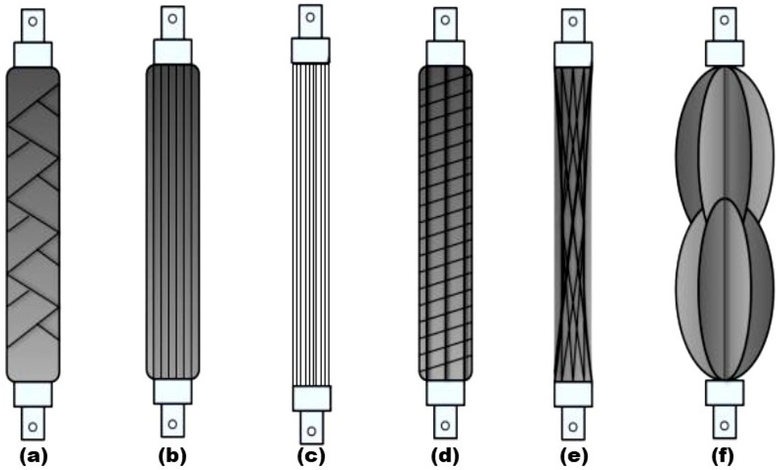
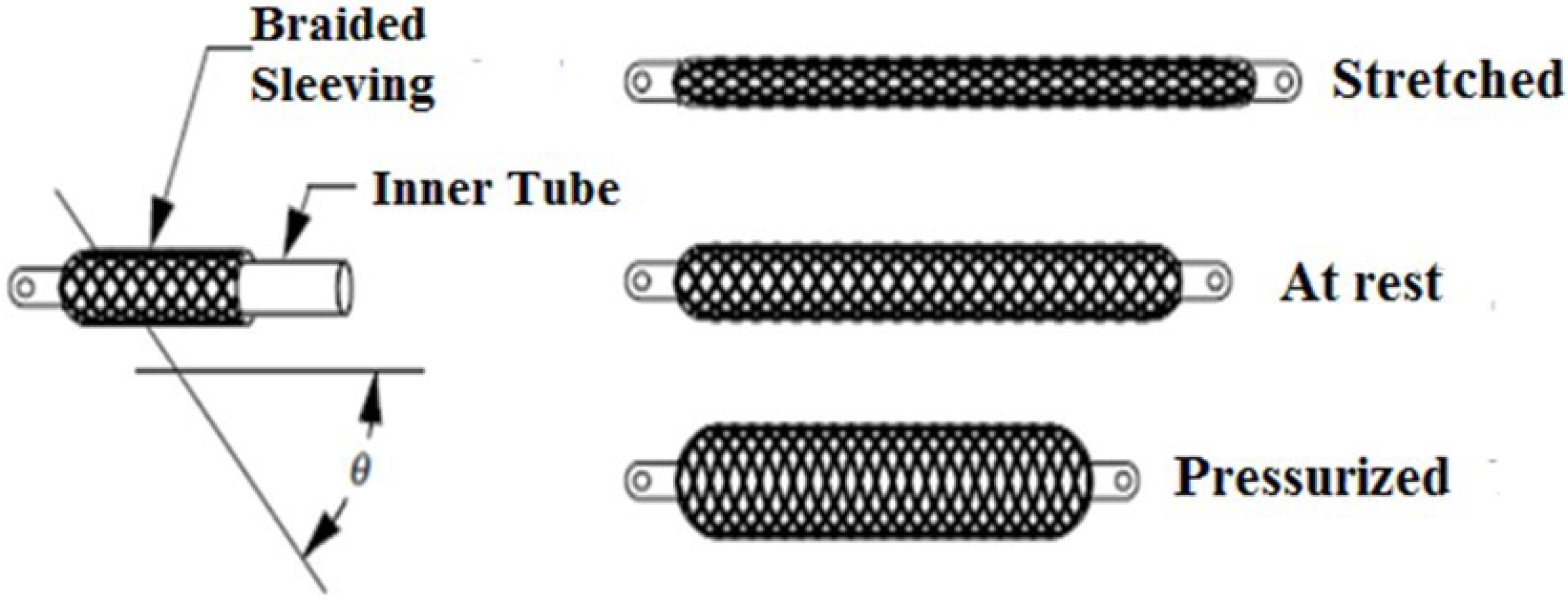
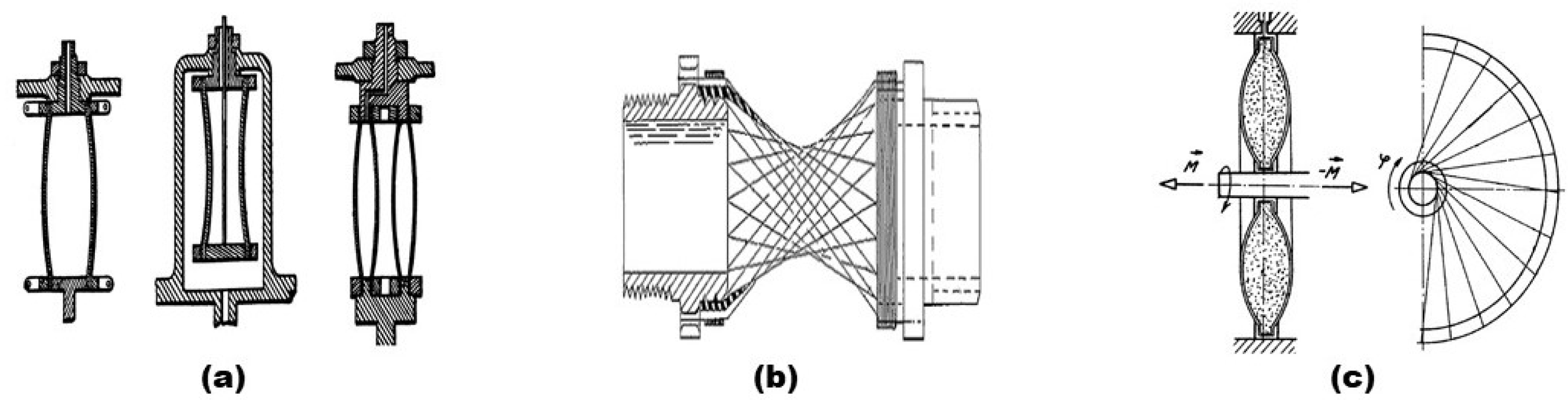
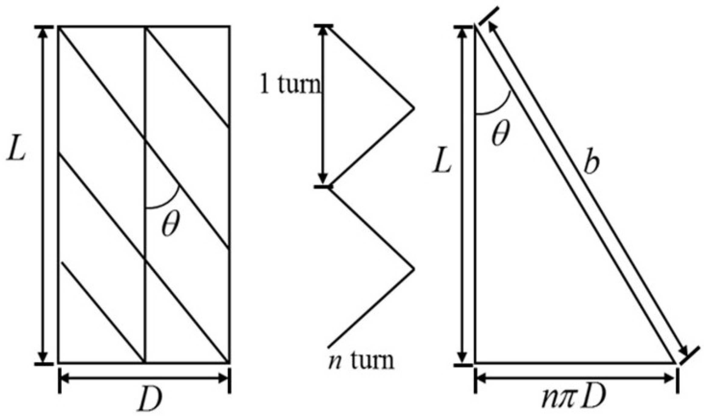
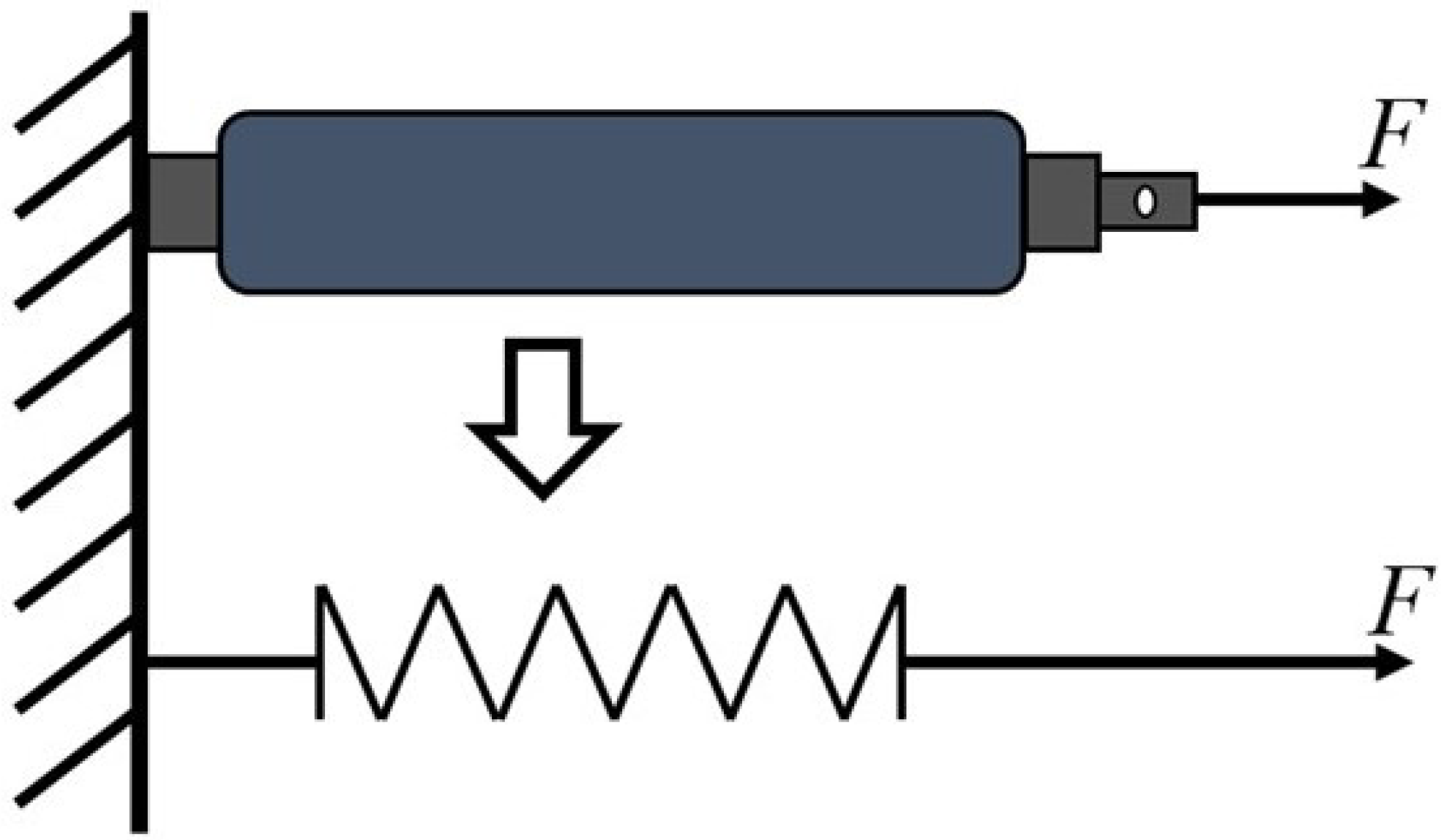
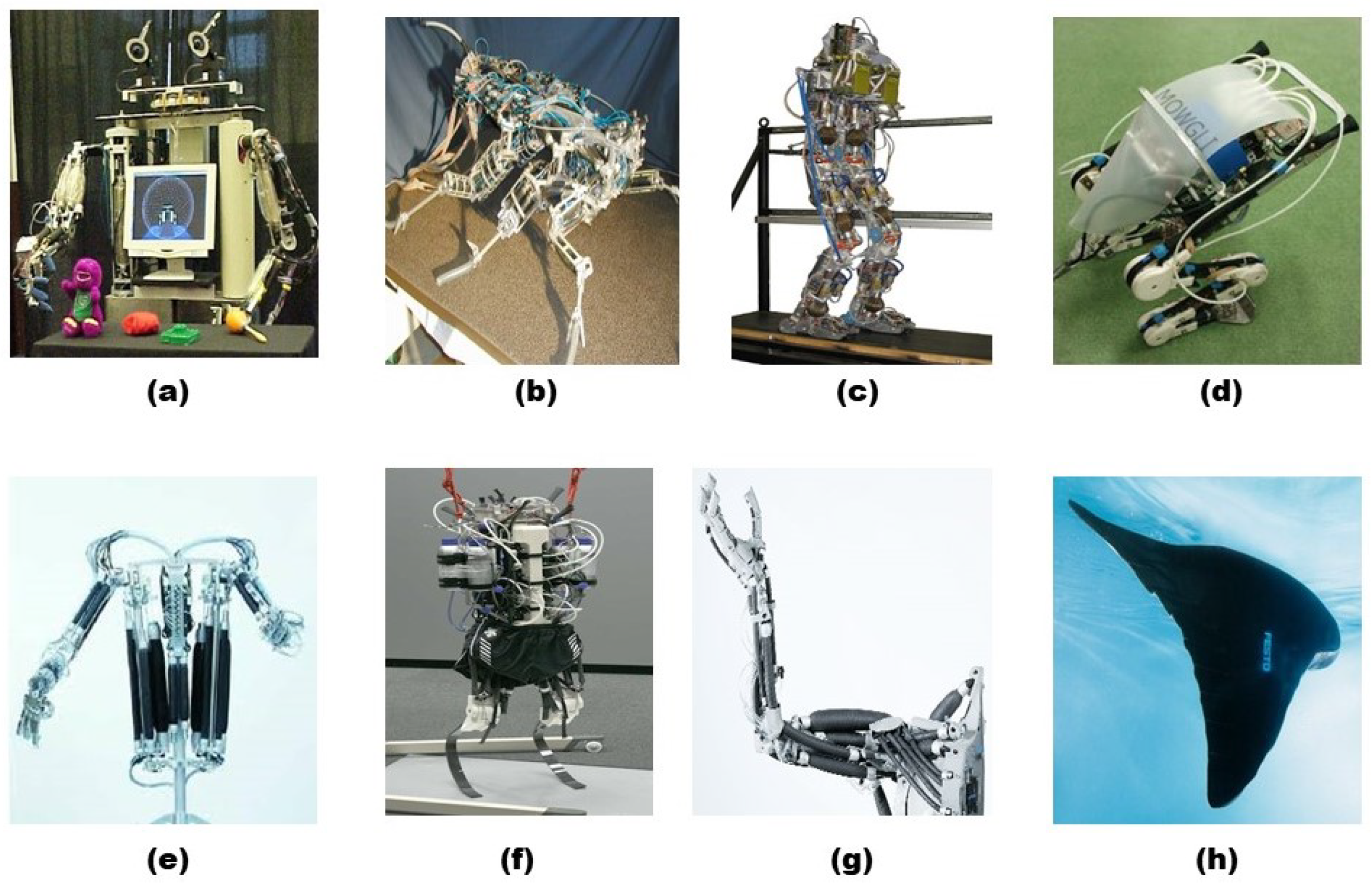
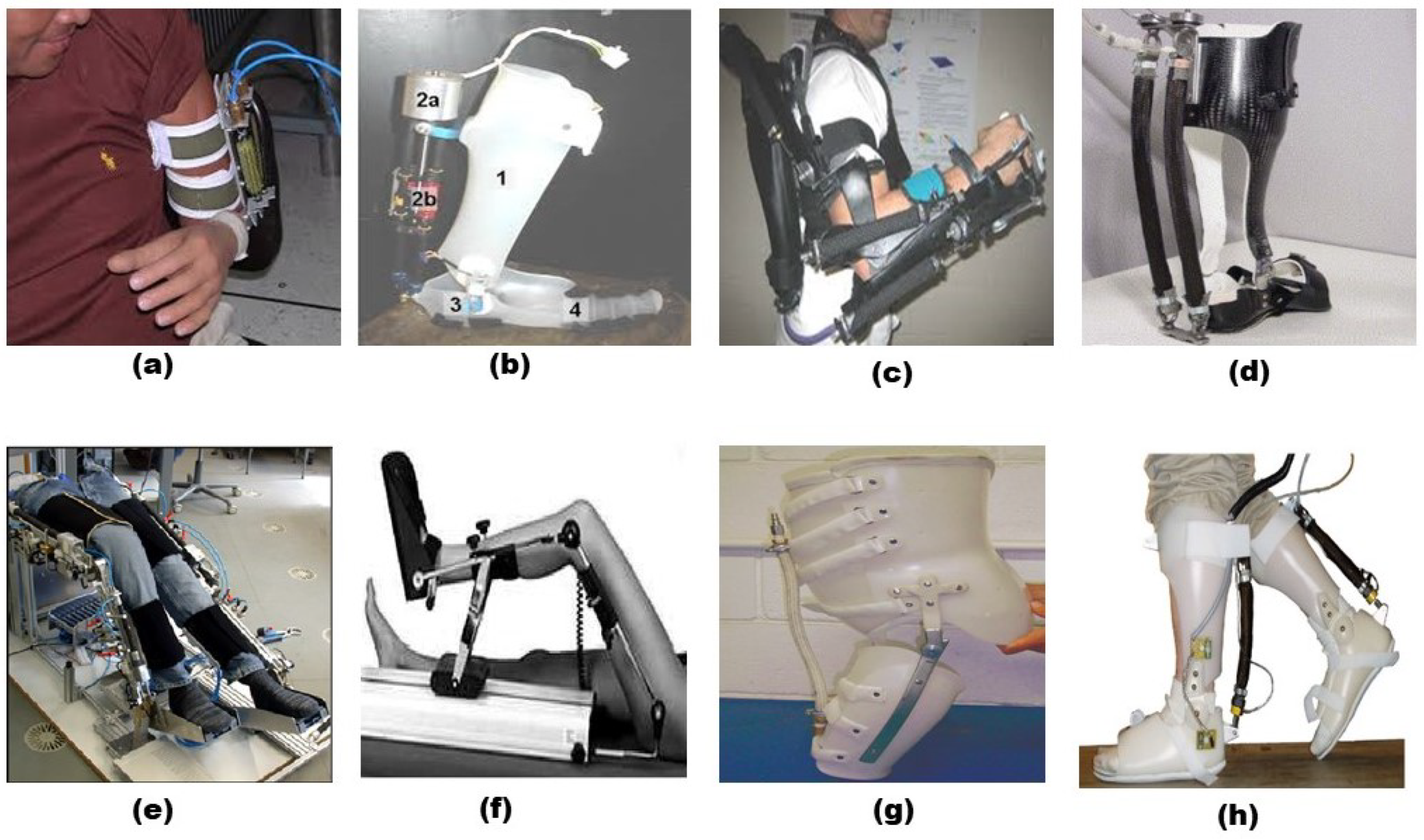
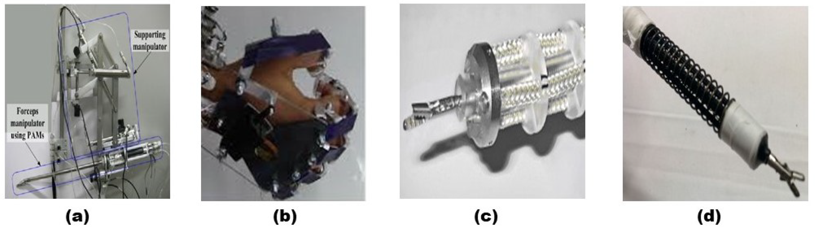
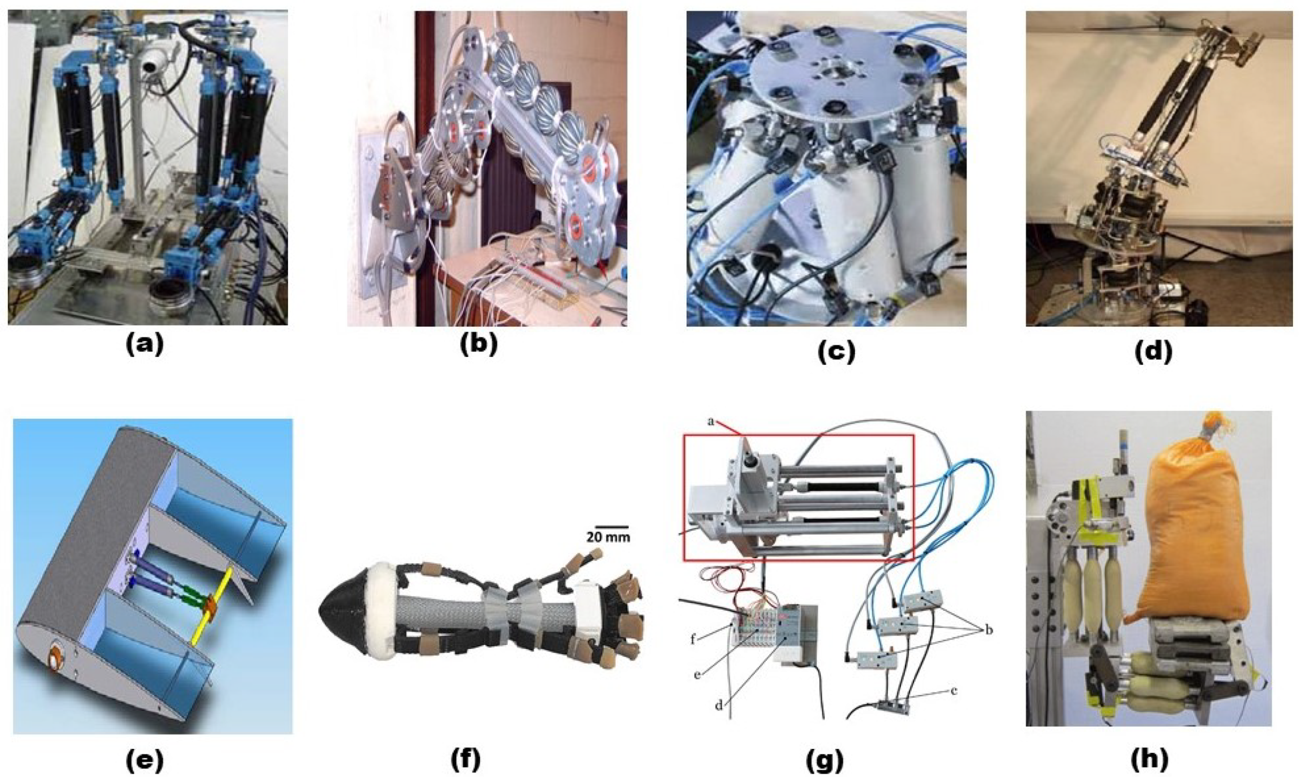
Table 1.
Comparison of actuator technologies [13].
Table 1.
Comparison of actuator technologies [13].
| Actuation Technology | Maximum Strain | Actuation Stress (MPa) | Specific Work (J/kg) |
|---|---|---|---|
| Hydraulic | 1 | 70 | 35,000 |
| Electromechanical | 0.5 | 1 | 300 |
| Solenoid | 0.4 | 0.1 | 5 |
| Piezoelectric | 0.002 | 9 | 1 |
| Magnetostrictive | 0.002 | 200 | 20 |
| SMA | 0.07 | 700 | 4500 |
| Pneumatic Cylinder | 1 | 0.9 | 1200 |
| PAM | 0.4 | 16 | 4400 |
Table 2.
Muscle force equations of considered for various models of PAM.
| Author | Muscle Force Equation |
|---|---|
| Schulte [30] | |
| Carlo Ferraresi et al. [79] | |
| Liu and Rahn [80] | |
| Delson et al. [81] | |
| Davis and Caldwell [82] | |
| Trivedi et al. [83] | |
| Doumit [84] | |
| de Volder et al. [85] | |
| Chen and Ushijima [86] | |
| Wang et al. [87] | |
| Hocking and Wereley [88] | |
| Sangian et al. [89] | |
| Andrikopoulos et al. [90] |
Publisher’s Note: MDPI stays neutral with regard to jurisdictional claims in published maps and institutional affiliations. |
© 2022 by the authors. Licensee MDPI, Basel, Switzerland. This article is an open access article distributed under the terms and conditions of the Creative Commons Attribution (CC BY) license (https://creativecommons.org/licenses/by/4.0/).
Share and Cite
MDPI and ACS Style
Kalita, B.; Leonessa, A.; Dwivedy, S.K. A Review on the Development of Pneumatic Artificial Muscle Actuators: Force Model and Application. Actuators 2022, 11, 288. https://doi.org/10.3390/act11100288
AMA Style
Kalita B, Leonessa A, Dwivedy SK. A Review on the Development of Pneumatic Artificial Muscle Actuators: Force Model and Application. Actuators. 2022; 11(10):288. https://doi.org/10.3390/act11100288
Chicago/Turabian StyleKalita, Bhaben, Alexander Leonessa, and Santosha K. Dwivedy. 2022. "A Review on the Development of Pneumatic Artificial Muscle Actuators: Force Model and Application" Actuators 11, no. 10: 288. https://doi.org/10.3390/act11100288
Note that from the first issue of 2016, this journal uses article numbers instead of page numbers. See further details here.