
A Design of Biomimetic Prosthetic Hand
by

Sakura Narumi
1, 
Xiansong Huang
1,
Jongho Lee
2,
Hiroyuki Kambara
3,
Yousun Kang
3 and
Duk Shin
4,* 1
Graduate School of Engineering, Tokyo Polytechnic University, 1583 Iiyama, Atsugi 243-0297, Japan
2
Department of Clinical Engineering, Komatsu University, He 14-1 Mukai-motoori-machi, Komatsu 923-0961, Japan
3
Information Technology Course, Faculty of Engineering, Tokyo Polytechnic University, 1583 Iiyama, Atsugi 243-0297, Japan
4
Mechanical Engineering Course, Faculty of Engineering, Tokyo Polytechnic University, 1583 Iiyama, Atsugi 243-0297, Japan
*
Author to whom correspondence should be addressed.
Actuators 2022, 11(6), 167; https://doi.org/10.3390/act11060167
Submission received: 19 April 2022
/
Revised: 18 May 2022
/
Accepted: 14 June 2022
/
Published: 16 June 2022
(This article belongs to the Special Issue Intelligent Robotic and Prosthetic Hands: Design, Control and Application)
Abstract
:Many patients with upper limb defects desire myoelectric prosthetic hands, but they are still not used for some reasons. One of the most significant reasons is its external appearance, which has the discomfort caused by the structural difference between a human hand and a robotic link. The structure must be based on human anatomy to create a more natural-looking prosthesis. This study designed a biomimetic prosthetic hand with bones, ligaments, tendons, and multiple muscles based on the human musculoskeletal system. We verified the proposed prosthetic hand using the viscoelastic angle sensor to determine whether it works like a human hand. We also compared the finger force of the prosthetic hand with that of a human finger. It could be capable of controlling the angle and the stiffness of the joint by multiple extensor and flexor muscles, like humans.
1. Introduction
Since the human hand is an important tool to interact with the environment, hand loss is one of the most disabling diseases which can affect amputees’ quality of life (QOL) and activities of daily living (ADLs). When humans move their hands, commands from the brain generate biological signals which cause the muscles to contract. These signals are called the myoelectric signals. Myoelectric prosthetic hands use myoelectric signals to control. The myoelectric prosthesis was developed for the first time in 1944–1948 by Reinhold Reiter, a physics student at Munich University [1]. This system was not suitable to carry because it used vacuum tubes. The first commercial myoelectric prosthesis, which we called ‘Russian Hand’, was made by the Central Prosthetic Research Institute in the former Soviet Union and has been on the market since 1965 [2]. It still has some problems, such as heavy, slow movements, and weak-grasping force. By the mid-1970s, the Ottobock system hand was developed by the German company Ottobock. From the 1980s, myoelectric prostheses were being used in rehabilitation around the world, and today, they are a common option for amputees [3]. However, the penetration rate of myoelectric prostheses in Japan is only 2% (for prosthetic hand users with one forearm amputation) [4].
The three major causes of low rate were cost, functionality, and external appearance. In the same survey, when asked how much they would pay out of pocket for a myoelectric prosthetic hand, the most common answer was between 10,000 yen and 300,000 yen. The forearm myoelectric prosthetic arm, which has a near monopoly of the global market share, is sold for over 1.5 million yen. This is far more than amputees can afford. Another major cause is functionality. For several decades after its sale, the functional aspect of the system still has low degrees of freedom: griping motion and internal/external rotation of the wrist and in terms of control, only on/off control using a threshold value of myoelectric signals or proportional control of hand-opening/closing speed and grasping force based on the strength of the myoelectric signals. In the past two decades, the research community has developed some novel artificial hands [5,6,7,8]. Most research groups aim to add the movement of human hands in a mechanized design, improving the functionality and performance of the prosthetics. However, they still avoid choosing it because of the different appearance from the human hands, such as the distortion and strange wrinkles of the silicone skin and the protruding robotic link. It does not significantly exceed the body-powered prosthetic hand in functionality. It is believed that many amputees want to have an anthropomorphic-appearance hand, which is an adequate image of the functionality of the myoelectric prosthetic hand. Although the prosthetic hand offers amputees a new opportunity of living a quality life, the reason many of them still do not use a prosthesis is dissatisfaction with their devices [9].
Wilkinson et al., proposed an anatomical robotic hand by replicating the bone structures of the fingers, which is the first robotic hand based on human-hand anatomy [10]. For many years, there has been much effort devoted to the designing and building of anthropomorphic robotic hands [10,11,12,13,14]. They molded cadaver bones and mimicked their joint structures by encapsulating viscous materials with a ligament-like structure. These studies of highly bionic anthropomorphic robotic hands have shown the possibility of replicating the structure of the human hand on the prosthesis to make the movements more dexterous. However, they controlled the finger with RC motor one-to-one correspondence. Since human joints are composed of multiple muscles for extensors and flexors, it needed to be controlled multi-to-one for making a human-like musculoskeletal system.
The aim of this study designed novel biomimetic fingers and controlled the multiple extensors and flexors with DC motors. We proposed the design replicates index and thumb from bones, ligaments, tendons, and the agonist–antagonist muscle mechanism. It intended to develop a prosthesis that has the same flexibility and anthropomorphic appearance as the human hand. To evaluate the performance of the proposed prosthetic in daily life, we conducted multiple finger movements and showed the feasibility of the proposed to solve the three problems stated above.
2. Materials and Methods
2.1. Bone
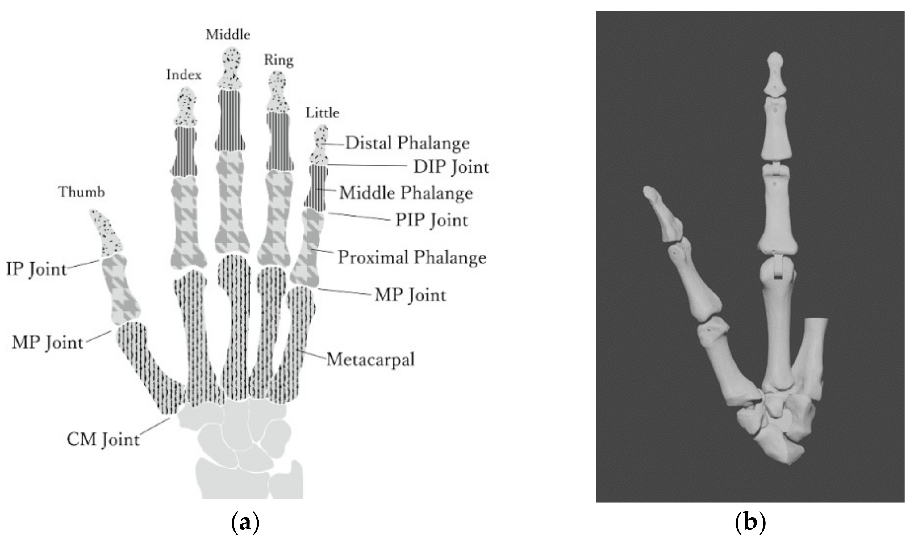
We described the design intent of the bone model used in the experiments. The finger skeletal structure comprises the metacarpal and phalangeal bones, as shown in Figure 1a. The human finger comprises the distal, middle, and proximal phalanges and metacarpals. These four bones make up the distal interphalangeal (DIP), proximal interphalangeal (PIP), and metacarpophalangeal (MCP) joints of the finger. The thumb finger has only two phalanges; thus, it has only one interphalangeal joint. The DIP and PIP joints are collectively referred to as the IP joint. The 3D model of the phalanges is based on the Biomimetic Robotic Prosthetic Hand published on the website GrabCAD.
Since there are individual differences in hand size and finger length, we adjusted the proportions of each bone in the 3D model of the phalanges, as shown in Table 1, referring to the average hand-size data of Japanese women [15]. The size of the hand model is equivalent to that of a female (159 cm, 52 kg). The overall view of the phalange’s 3D model is shown in the right of Figure 1b.
2.2. Joint
The DIP, PIP, and MP joints of index, and the IP and MP joints for thumb are capable of flexion and extension. Table 2 summarizes the range of motion of these joints between the human and the proposed hand and the basic axis and the movement axis during the motions [16]. Since the range of motion of the human finger varies from person to person, we have designed the prosthetic hand with a margin of freedom where possible. The angular velocity during flexion and extension of the index of the prosthetic hand we created was 1.85 [rad/s], and the angular velocity during flexion and extension of the thumb was 1.31 [rad/s].
The 3D model of phalanges was designed with link structures that follow the range of motion and prevent hyperflexion and hyperextension. The IP and MP joints of the thumb also have a link structure for the same reason. These joints have structures called hinged joints, which are uniaxial joints that move only in one direction with the cylindrical axis of motion, as shown in Figure 2a.
The CM joint of thumbs is the biaxial joint called the articulatio sellaris [17]. As shown in Figure 2b, the thumb can perform rotational motion by combining two degrees of freedom of motion. It is said that for the myoelectric prosthetic thumb to be capable of rotational motion, the joint must have at least three degrees of freedom because a disordered drive must be considered. For this reason, we designed a spherical joint with a ball and socket, as shown in Figure 2c.
2.3. Ligament
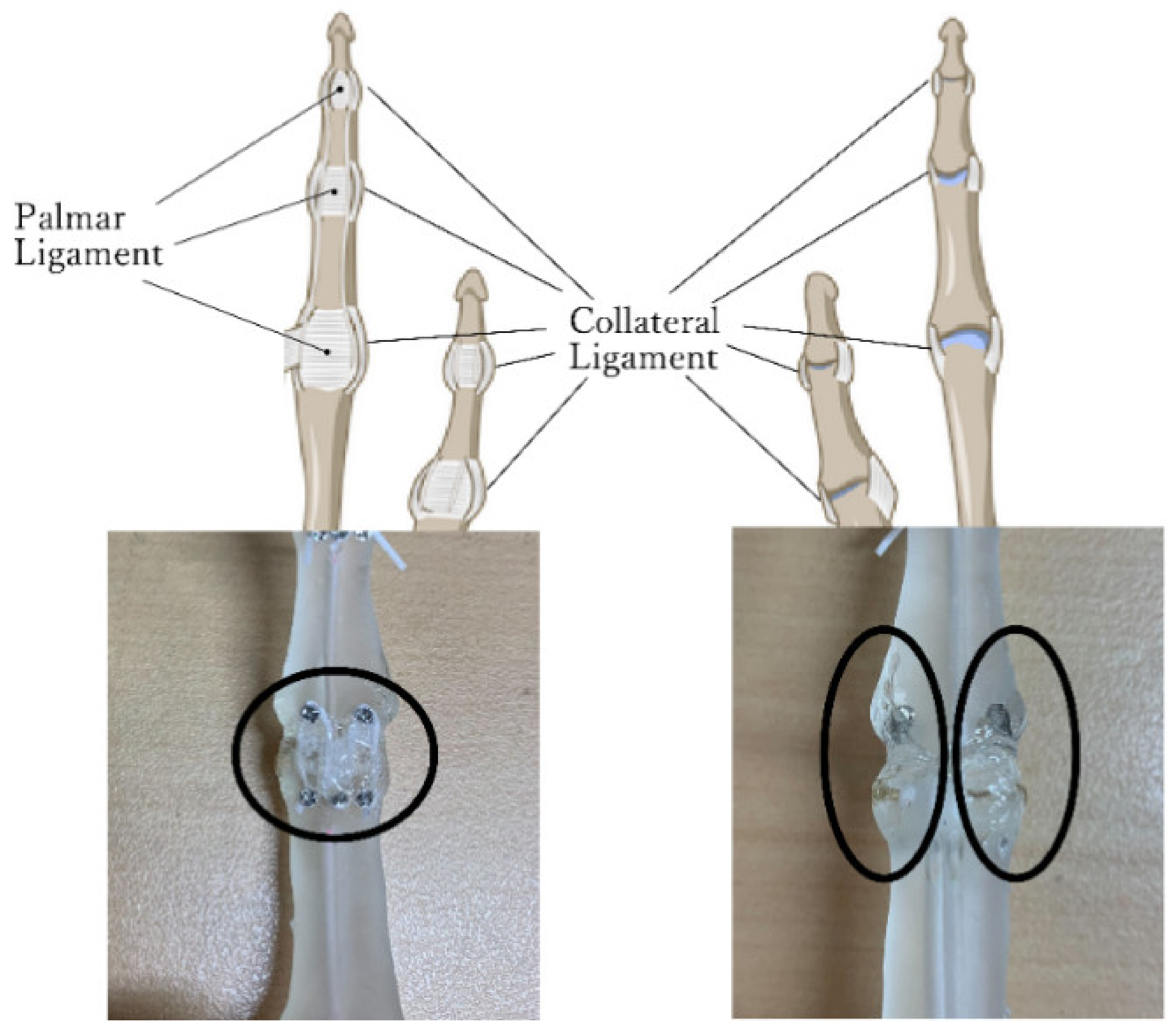
Index fingers have two types of ligaments, the palmar and collateral ligaments, as shown in Figure 3. Collateral ligaments control the excessive lateral movements of the joints and maintain the stability of joint parts. In this study, collateral ligaments were simulated by using an adhesive. Figure 3 shows the collateral ligament portion of the phalanx model used in the experiment. Two types of viscoelasticity adhesives were used: E6000 sold by Eclectic Products, Inc. and cemedine BBX sold by CEMEDINE CO. Comparing these two adhesives, E6000 has higher adhesive strength and is slightly sticky after drying, while cemedine BBX has a slightly softer adhesive part after drying and is more stable in the joint area. Therefore, the use of E6000 on top of cemedine BBX reproduced the collateral ligaments, which allow soft movements while maintaining joint stability.
Palmar ligaments prevent hyperextension of the joint. To reproduce this function, the design is shown in the right panel of Figure 3. A precision screw (M1.2 × 2.5 mm) is attached to each phalanx, and an elastic rubber strap (1 mm wide × 0.37 mm thick) is hung, as shown in the right panel of Figure 3. In this way, the palmar ligament, which is pulled by the finger extension and folded by the finger flexion, is simulated. The same design applies to the IP and MP joints of the thumb since these ligaments exist in the same way as those of the index fingers.
As described in Section 2.2, the saddle joint has higher freedom than other joints of the finger. Therefore, the ligaments of the CM joint of the thumb function to maintain the stability of the joint by restricting the excessive motion of the spherical joint. As in the index finger, the phalange model was made to simulate the ligaments with precision screws, rubber strings, and viscoelastic adhesives. These also prevent excessive rotation of the thumb CM joint which is designed as a spherical joint.
2.4. Tendon/Tendon Sheath
The muscles that perform the finger movements are connected to the phalanges by tendons. The tendons pass through a tunneled tube called a tendon sheath to prevent the tendons from floating due to finger motion. Previous works [10,11,12,13,14] used rubber hood or crocheting nylon to emulate the geometry and functionality of the tendon sheath as closely as possible. However, it was not durable and could not be used for a long time. In the phalange model of this study, this tendon sheath is reproduced by designing a tunnel-like hole in the phalanges, as shown in Figure 4a. A thread that resembles a tendon is passed through this tunnel, and the movement of the finger is reproduced by controlling the thread. We used fishing line as tendons.
2.5. Muscles
The muscles involved in the flexion and extension of index fingers are summarized in Table 3. Two major muscles are involved in the flexion of fingers except thumbs: the flexor digitorum superficialis and the flexor digitorum profundus. The flexor digitorum profundus muscle passes through the tendon sheath and stops at the distal phalanges of the index with little fingers. The flexor digitorum profundus mainly affects the flexion of the PIP joint besides the DIP joint. Extensor digitorum muscles are used to extend fingers other than thumbs. It begins at the lateral epicondyle of the humerus, and the tendon divides into four parts, stopping at the middle phalanges and distal phalanges of each phalange of index to little fingers. The index finger has an extensor muscle different from the extensor digitorum muscle called the extensor indicis muscle. Therefore, it can be extended regardless of the posture of the middle and ring fingers. As shown in Table 3, lumbricals, palmar interossei, and dorsal interossei are muscles involved in both flexion and extension movements. The extensor digital expansions are membranous tissues that incorporate the extensor digitorums, lumbricals, and interossei muscle. Not only the extensor digitorums and flexor muscles but also lumbricals and interossei muscles act to enable complex finger movements.
Muscles involved in flexion and extension, adduction and abduction of thumbs are shown in Table 4. Flexion of the thumb is mainly mediated by flexor pollicis longus and flexor pollicis brevis. Flexor pollicis longus does not pass through the ulnar bursa but through the unique synovial sheath. Therefore, thumbs have a higher freedom of movement than the other fingers. The flexor pollicis longus is involved in the flexion of each joint of the thumbs. The extensor pollicis longus is the muscle that is largely involved in the extension of thumbs. The adduction of the thumb is mainly performed by the adductor pollicis. It is the deepest of the flexor muscles on the palmaris. It begins at two locations on the index and middle finger metacarpals and stops near the thumb proximal phalange. The abduction of a thumb is largely controlled by the abductor pollicis longus. It starts from the forearm and stops at the metacarpal of the thumb. It is involved in both palmar and flexor abduction of the thumb’s MP joint.
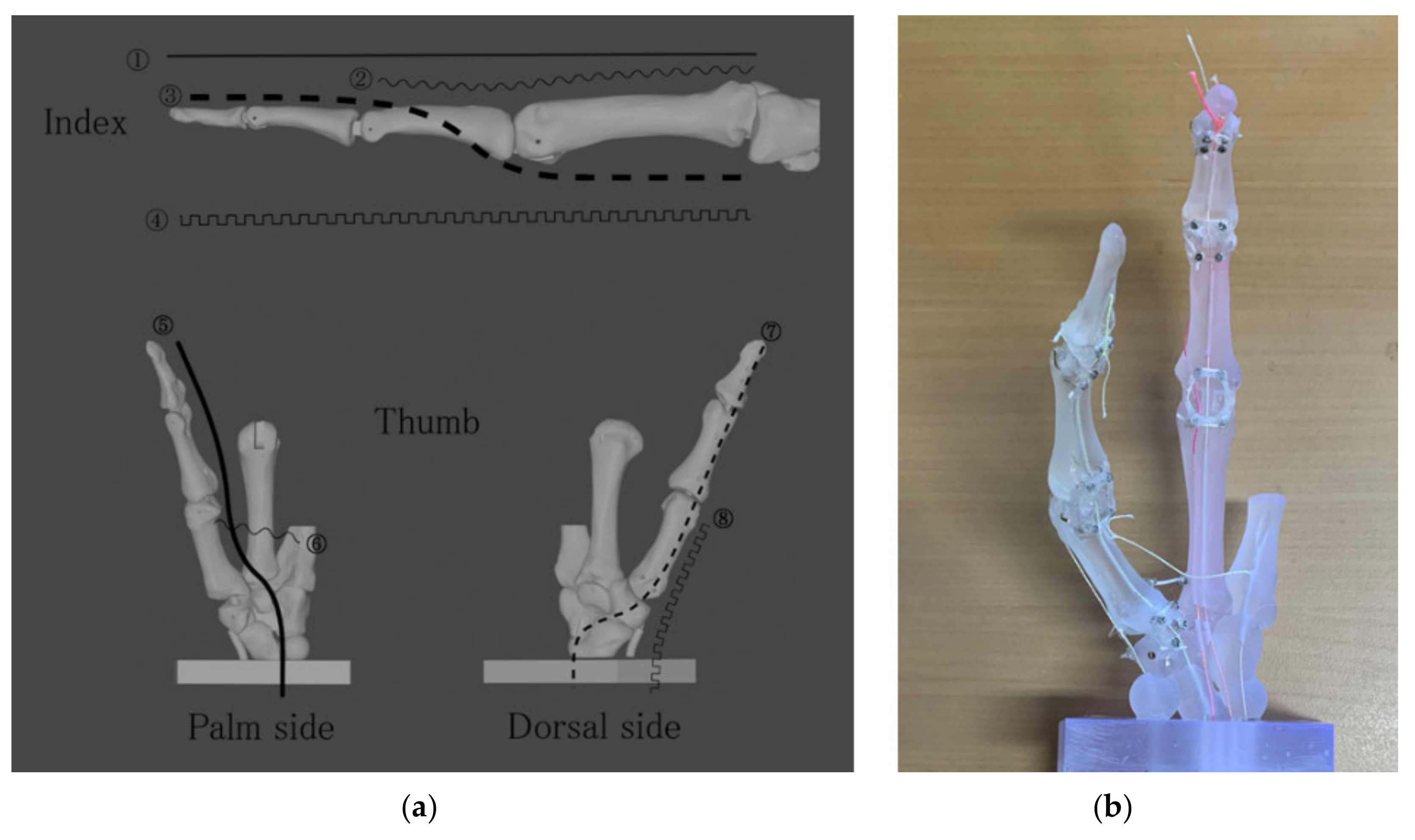
The aforementioned muscles enable the hand to perform a variety of movements. When developing a prosthetic hand, it is necessary to reproduce various movements with a minimum number of motors, taking weight and cost into consideration. In this study, we designed a tendon sheath for eight tendons, four each for the index finger and thumb, on the phalange model. The actual trajectories are shown in Figure 5a. The completed actual phalange model is shown in Figure 5b.
2.6. Motors and Control Board
A thread resembling a tendon was threaded along the path of the tendon sheath of the index and thumb, which was controlled by a motor. Four motors were used for the index finger and two for the thumb. The thumb was controlled by one motor each for (5) and (7), (6) and (8) as shown in Figure 5a. By controlling adduction/abduction and flexion/extension with separate motors, we aimed to realize various thumb motions with a minimum number of motors. The index finger was controlled by separate motors for each of the four tendons. The index finger can assume a posture in which the IP joint and MP joint are in opposition (MP joint extension during IP joint flexion and IP joint extension during MP joint flexion). To achieve this posture, the tendons that extend and relax must be varied depending on the situation. It is also important for the index finger to be sensitive to pinching movements. Therefore, we used four DC motors with planetary gear for the index finger.
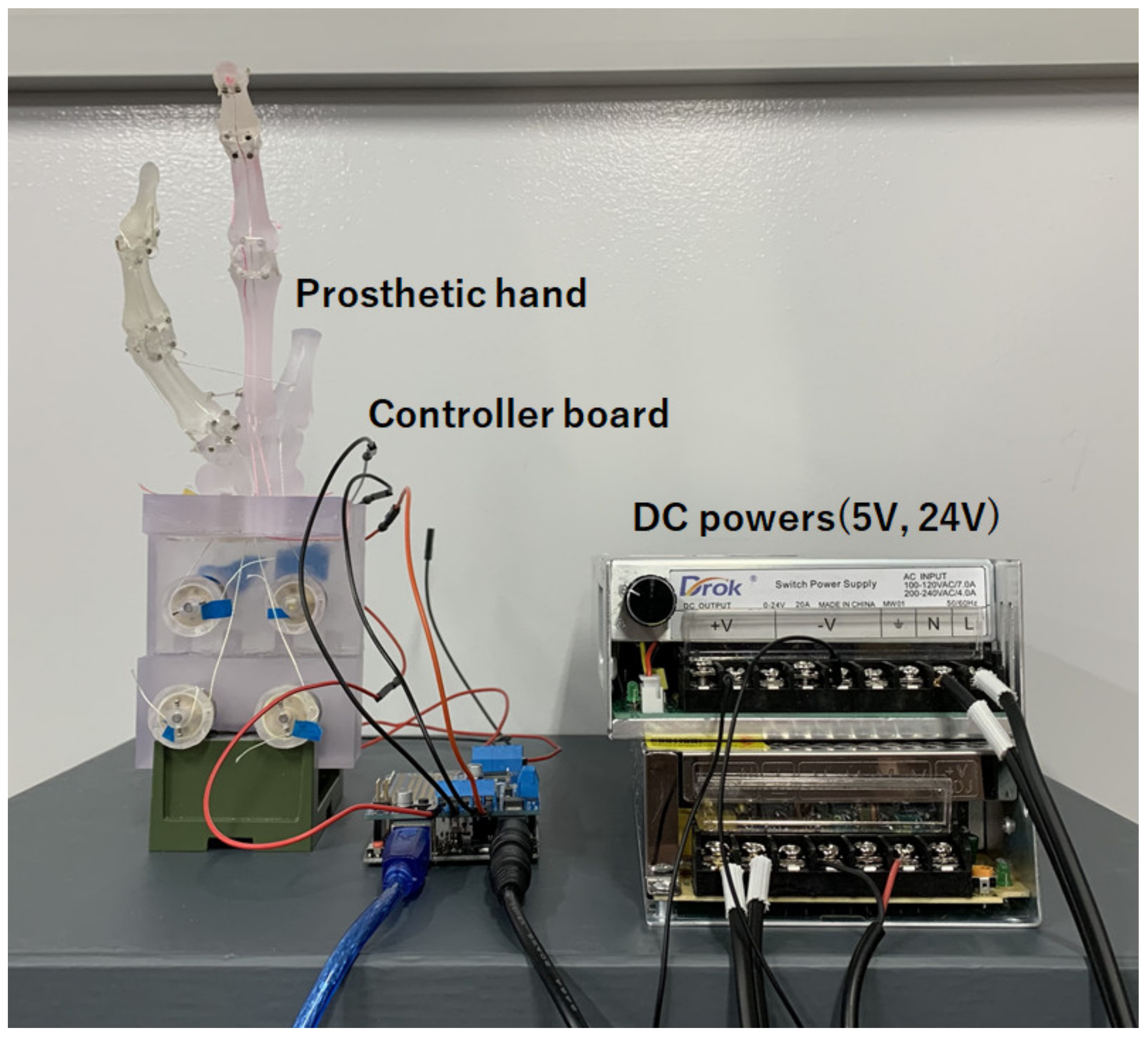
We used an Arduino board (Arduino Uno, Arduino.cc, Monza, Italy) and motor shield (V2.3, Adafruit Co.) that controls DC motors simultaneously, as shown in Figure 6. Serial communication with 115,200 bps was used for the data communication between the host PC and the Arduino controller board by connecting the USB micro cable. The 12 V, 400 rpm DC motor with metal planetary gear (Hilitandxw3qy9g0p5-13, Hilitand Co., ShenZhen, China) was used. This prosthesis system was very cheap, under USD 100.
2.7. Sensors
Two important proprioceptors that play a role in flexibility are the muscle spindle and the Golgi tendon organ. Figure 7a shows the viscoelastic angle sensor (custom-made, Feel the Same LLC., Ulsan, Korea) with silicon and liquid metal. The sensor measures the angle of a finger based on the resistance value of the liquid metal, which changes as the metal strain gages. The output voltage returns the amount of change in resistance between 0 to 1, which applies to the angle range set by the user. The angle range except DIP joint was set from 0° to 100°, and from 0° to 80° only for the DIP joint. The sensitivity of the sensor was set to 0.01. For the index finger, sensors are attached only to the PIP and MCP joints, and the DIP joint values are calculated from the PIP joint values. Each sensor measures the angles of the DIP and PIP joints of the thumb but cannot measure the angle of the CMC joint. The sensors are wireless and run using Unity. The program that scans the sensor values is in the update method; thus, the angle is measured every frame. Therefore, the number of scans per second depends on the specifications of the PC. In the environment of this study, about 100 scans were performed per second. Figure 7b shows the hand in the open and grasped states. When the sensor is attached to the prosthetic hand, it is useful to measure the hand gestures.
2.8. Experiments
To investigate the possibility of controlling multiple muscles attached to the index phalanx, we experimented with the three types of the index operations. The duty rate of the motor PWM command can be changed with commands from 0 to 99. Before conducting the experiment, the operation of the motor used in this project was checked. To stabilize the rotation of the motor, it was limited to the maximum value of 90. The speed setting of the motor was changed in increments of one. When the prosthetic hand was attached and the fishing line was pulled, the fingers could not be moved unless set to a minimum of five, and even then, they could not be bent and extended perfectly unless set to ten. Therefore, experiments were conducted between 10 and 90.
We compared the index force between the proposed index and the human index finger (female; 162 cm, 52 kg). A dual-range force sensor (DFS-BTA, Vernier Co., Beaverton, USA) was used in the experiments with a sensor resolution of 0.01 N. We tied a string to the PIP joint of the index finger and attached the string to the force sensor. In this initial state, the index finger is momentarily flexed. This was performed on both a human and the prosthetic hand. The length of the thread from the force sensor to the index DIP joint was 8 cm.
3. Results
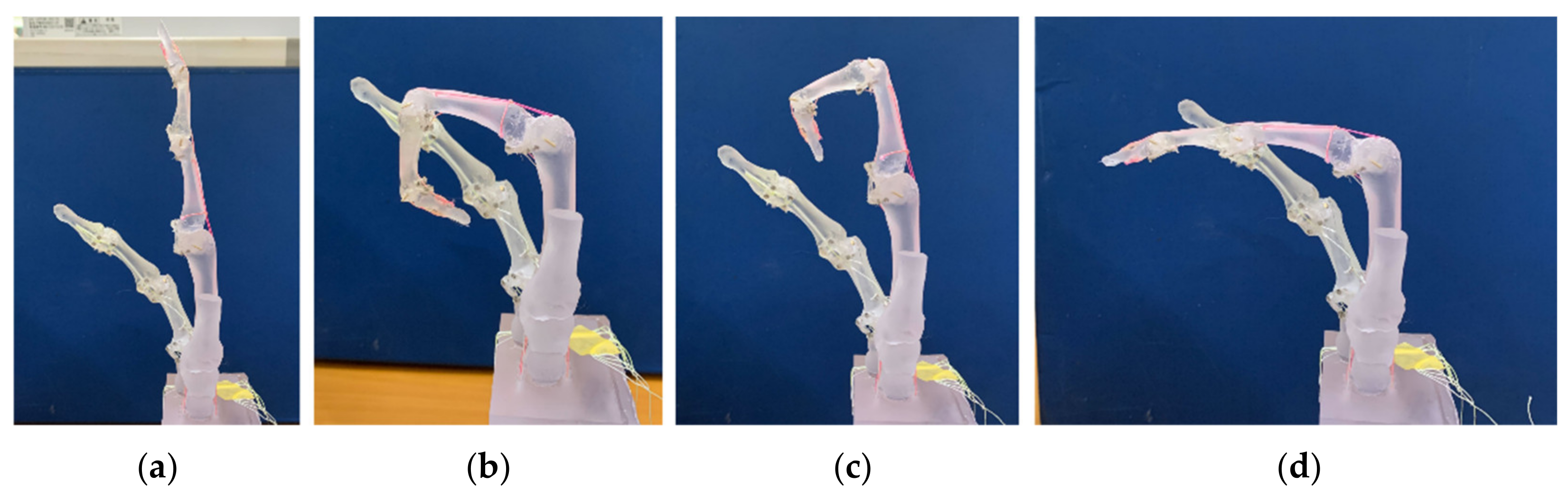
Figure 8 shows each operation of the index finger with multiple muscles. We confirmed that four motors with metal planetary gear instead of four muscles enable complex human-like movements, such as IP/DIP joint operation (Figure 8c) and MP joint only operation (Figure 8d), different from conventional flexion movements, as shown in Figure 8b. We showed the angle motion of a human index finger (upper panels) with those of a robot (bottom panels) using a liquid metal sensor, as shown Figure 9. Since the angular pattern of each joint was compared between the human and robot, we found similar characteristics to human, such as the angle size and the order of each joint stand up. We showed the control of stiffness using co-contraction to modulate stiffness by activating extensor and flexor muscles simultaneously (Videos S4 and S5 in Supplementary Materials).
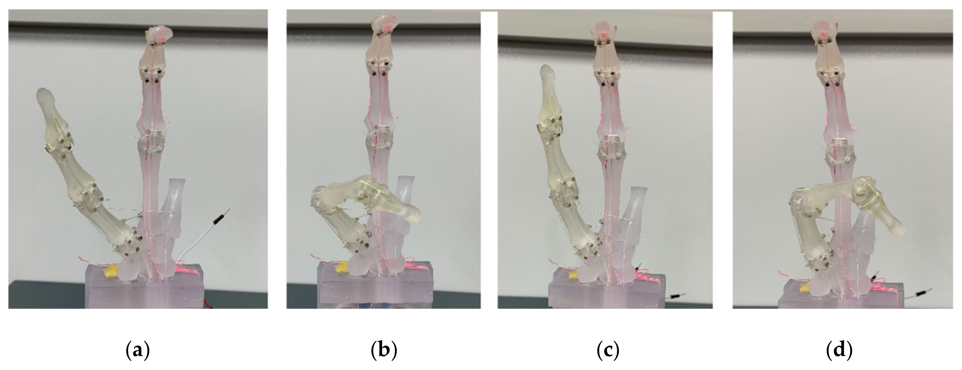
We also reproduced thumb movements, as shown in Figure 10. The thumb has a complex movement, but as mentioned above, the proposed hand has four muscles: extensor, flexor, abductor, and adductor muscles. It showed the difference between abduction (Figure 10a) and adduction (Figure 10c). Complex motions of the thumb could be reproduced, such as IP/MP flexion with CM abduction (Figure 10b) and IP/MP flexion with CM adduction (Figure 10d). We, however, could not record these complex motions of the thumb from the attached sensor alone, except for flexion and extension (Figure S1). As for the thumb, the sensor needs to be redesigned to measure these compound motions.
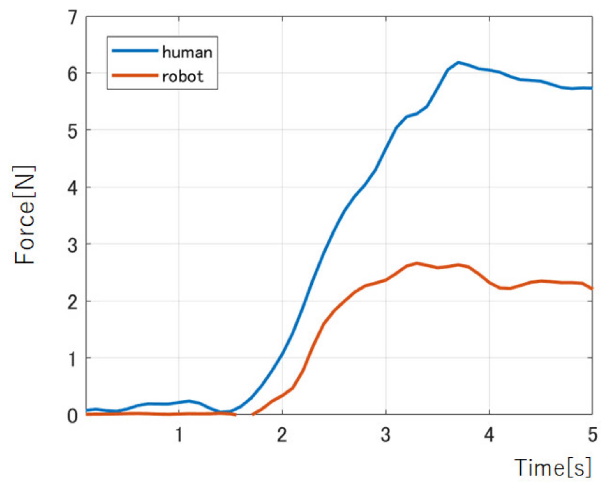
The results of the measurement by the force sensor are shown in Figure 11. The maximum force of the human index during instantaneous bending was 6.19 N. It took 1.74 s from the start of the flexion motion to the maximum force. In the prosthetic’s case, the maximum force was 2.68 N, and it took 1.46 s from the start of the motion to reach the maximum force. It shows that the proposed prosthetic hand could exert about 44% force of the female finger force.
4. Discussion
Many studies have been reported on how many degrees of freedom, operating ranges, and their state-of-the-art control techniques. However, the reason the supply rate of the myoelectric prosthesis is still low in Japan, despite this innovative technology, is that it did not give a solution to the needs of amputee. These electric prosthetic hands have been difficult to put into regular use, partly because they are expensive, but also because the disabled are shunned wearing them because of the extra wrinkles and skin distortion.
The needs of physically disabled people are (1) production of a motorized prosthetic hand with a good decorative appearance and multiple degrees of freedom, (2) acquisition of wide mobility that can be used in daily life without inconvenience and limited pattern movements, (3) viscoelastic control that enables interaction with objects, (4) no training required control method, and (5) low cost.
Conventional motorized prosthetic hands only cover the mechanic link structure of the robotic hand with silicone skin. Between motion to bend more, the extra wrinkles, and skin distortion cause an “uncanny valley” phenomenon. To solve this problem, it is necessary to design a link structure based on the musculoskeletal system, which has a structure similar to that of humans rather than the link structure of a robot. The proposed design based on skeletal anatomy shows the natural expression of bone shape when clenching a fist, not further causing the “uncanny valley”.
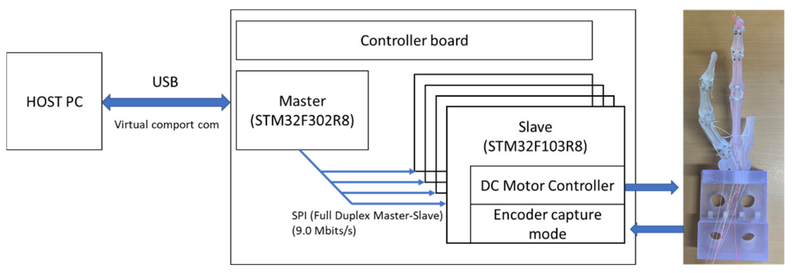
We recently showed the controller board can control DC motors simultaneously, as shown in Figure 12. Since the development of the control board with API is underway for issue (1) above, a myoelectric prosthetic hand with five fingers that has multiple degrees of freedom will be a future work. The issues (2)–(4) have not yet been solved in this study, but the proposed myoelectric prosthetic hand can express stiffness by controlling multiple extensor and flexor muscles from surface myoelectrogram (sEMG) signals. There was some research reporting on myoelectric prosthesis with the pattern recognition technique [18,19,20,21]. We have proposed a mathematical model to predict joint torque and stiffness from sEMG signals and have conducted research to effectively use not only kinematic information but also kinetic information. Our previous works reported the myokinetic (Mykin) model, which can estimate the angle, torque, and stiffness of joints from muscle activities [22,23]. Predicting the viscoelasticity of muscles is a key role since normal subjects interact with objects by adjusting the viscoelasticity of muscles based on predictions of the arm’s orbital coordinates in the outside world and the weight of the object. Using this research, future work will install the sEMG measurement and automatically control the motor with the calculated tension from sEMG signals. The missing muscle signals are proposed to be predicted from the remaining muscles using the muscle synergy methods [24,25,26,27].
In our previous works, we developed a method for estimating myoelectric signals and arm trajectories and forces in real time from electrocorticogram (ECoG) [28,29,30,31,32] and control of robotic arms using joint angles and myoelectric signals predicted by ECoG [33]. In patients who are completely deficient and unable to measure sEMG signals, these BMI techniques could control prosthetic hands.
Schoepp et al., (2018) demonstrated the functionality of an inexpensive tactile sensory feedback system for trans-humeral myoelectric prostheses [34]. This approach provides a platform for further investigation into the potential impact of sensory feedback on a functional task.
By integrating these results, it would be possible that physically disabled people can control the viscoelasticity of the artificial muscles that move the bones and joints, enabling them to interact with objects like able-bodied people.
5. Conclusions
This study proposed a skeletal electric prosthetic hand with bones, ligaments, tendon sheaths, tendons, muscles, and skin similar to the human skeletal system. We showed how to make it and demonstrated finger movements controlling multiple flexors and extensors.
By controlling viscoelasticity using a mathematical tension model of muscles without using machine learning, we will build a new basic technology for a motorized prosthetic hand that provides sufficient grasping force to enable most movements necessary for daily life and interaction with objects.
Supplementary Materials
The following supporting information can be downloaded at: https://www.mdpi.com/article/10.3390/act11060167/s1, Video S1: Flexion and extension of index with multiple muscles, Video S2: DIP/IP joints flexion and extension of index with 4 muscles, Video S3: MP joint flexion and extension of index with 4 muscles, Video S4: Low stiffness condition, Video S5: High stiffness condition, Video S6: IP/MP flexion with CM abduction of thumb, Video S7: IP/MP flexion with CM adduction of thumb, Figure S1: The angle trajectory of thumb flexion and extension.
Author Contributions
Conceptualization, Y.K. and D.S.; methodology, S.N. and D.S.; software, J.L. and Y.K.; validation, S.N., X.H. and D.S.; formal analysis, S.N.; investigation, D.S.; resources, S.N.; data curation, S.N.; writing—original draft preparation, S.N. and D.S.; writing—review and editing, D.S.; visualization, S.N. and D.S.; supervision, D.S.; project administration, H.K.; funding acquisition, Y.K. and D.S. All authors have read and agreed to the published version of the manuscript.
Funding
This work was supported by JSPS KAKENHI, Grant Number JP19K11428.
Institutional Review Board Statement
Not applicable.
Informed Consent Statement
Not applicable.
Data Availability Statement
Not applicable.
Acknowledgments
We would like to thank Fukuda, Shimizu, and He, past lab members, for the prototypes.
Conflicts of Interest
The authors declare no conflict of interest.
References
- Reiter, R. Eine neue Electrokunsthand. Grenzgeb. Med. 1948, 4, 133–135. [Google Scholar]
- Sherman, E.D. A Russian Bioelectric-Controlled Prosthesis. Can. Med. Assoc. J. 1964, 91, 1268–1270. [Google Scholar] [PubMed]
- Ribeiro, J.; Mota, F.; Cavalcante, T.; Nogueira, I.; Gondim, V.; Albuquerque, V.; Alexandria, A. Analysis of Man-Machine Interfaces in Upper-Limb Prosthesis: A Review. Robotics 2019, 8, 16. [Google Scholar] [CrossRef] [Green Version]
- Kawamura, J. Prospect for popularization of myoelectric hands. J. Jpn. Soc. Prosthet. Orthot. 2001, 17, 257–261. [Google Scholar]
- Okamoto, S.; Tamura, T.; Koike, M.; Takahashi, K. Survey of Attitude for Amputees of Hemi Lateral Forearm to Artificial Electric Arm. J. Natl. Rehabil. Cent. Disabl. 2001, 22, 55–61. [Google Scholar]
- Carrozza, M.C.; Suppo, C.; Sebastiani, F.; Massa, B.; Vecchi, F.; Lazzarini, R. The SPRING hand: Development of a selfadaptive prosthesis for restoring natural grasping. J. Auton. Robot. 2004, 16, 125–141. [Google Scholar] [CrossRef]
- Inouye, J.M.; Valero-Cuevas, F.J. Anthropomorphic tendon-driven robotic hands can exceed human grasping capabilities following optimization. Int. J. Robot. Res. 2013, 5, 694–705. [Google Scholar] [CrossRef]
- Kim, U.; Jung, D.; Jeong, H. Integrated linkage-driven dexterous anthropomorphic robotic hand. Nat. Commun. 2021, 12, 7177. [Google Scholar] [CrossRef]
- Brack, R.; Amalu, E.H. A review of technology, materials and R&D challenges of upper limb prosthesis for improved user suitability. J. Orthop. 2021, 23, 88–96. [Google Scholar]
- Wilkinson, D.D.; Vande Weghe, M.; Matsuoka, Y. An Extensor Mechanism for an Anatomical Robotic Hand. In Proceedings of the Conference on Robotics and Automation, Taipei, China, 14–19 September 2003; pp. 238–243. [Google Scholar]
- Matsuoka, Y.; Afshar, P.; Oh, M. On the Design of Robotic Hands for Brain Machine Interface. Neurosurg. Focus 2006, 20, E3. [Google Scholar] [CrossRef]
- Deshpande, A.D.; Balasubramanian, R.; Lin, R.; Dellon, B.T.; Matsuoka, Y. Understanding variable moment arms for the index finger MCP joints through the ACT hand. In Proceedings of the IEEE/RAS-EMBS International Conference on Biomedical Robotics and Biomechatronics, Scottsdale, AZ, USA, 19–22 October 2008. [Google Scholar]
- Xu, Z.; Todorov, E.; Dellon, B.; Matsuoka, Y. Design and Analysis of an Artificial Finger Joint for Antrhopomorphic Robotic Hands. In Proceedings of the IEEE International Conference on Robotics and Automation, Shanghai, China, 8–13 May 2011. [Google Scholar]
- He, Z.; Kang, Y.; Shin, D. A Design of Anthropomorphic Hand based on Human Finger Anatomy. Adv. Sci. Technol. Eng. Syst. J. 2021, 6, 431–438. [Google Scholar] [CrossRef]
- Kouchi, M.; Miyata, N.; Mochimaru, M. An Analysis of Hand Measurements for Obtaining Representative Japanese Hand Models. SAE Tech. Pap. 2005. [Google Scholar] [CrossRef]
- American Academy of Orthopaedic Surgeons. Joint Motion: Method of Measuring and Recording (Chicago); American Academy of Orthopaedic Surgeons: Rosemont, IL, USA, 1965. [Google Scholar]
- Hollister, A.; Buford, W.L.; Myers, L.M.; Giurintano, D.J.; Novick, A. The axes of rotation of the thumb carpometacarpal joint. J. Orthop. Res. 1992, 10, 454–460. [Google Scholar] [CrossRef]
- Dalley, S.A.; Varol, H.A.; Goldfarb, M. A Method for the Control of Multigrasp Myoelectric Prosthetic Hands. IEEE Trans. Neural Syst. Rehabil. Eng. 2012, 20, 58–67. [Google Scholar] [CrossRef] [Green Version]
- Iqbal, N.V.; Subramaniam, K.; Asmi, P.S. A Review on Upper-Limb Myoelectric Prosthetic Control. IETE J. Res. 2018, 64, 740–752. [Google Scholar] [CrossRef]
- Toledo, C.; Leija, L.; Munoz, R.; Vera, A.; Ramirez, A. Upper limb prostheses for amputations above elbow: A review. In Proceedings of the Pan American Health Care Exchanges, Mexico City, Mexico, 16–20 March 2009; pp. 104–108. [Google Scholar] [CrossRef]
- Wang, Y.; Tian, Y.; She, H.; Jiang, Y.; Yokoi, H.; Liu, Y. Design of an Effective Prosthetic Hand System for Adaptive Grasping with the Control of Myoelectric Pattern Recognition Approach. Micromachines 2022, 13, 219. [Google Scholar] [CrossRef]
- Shin, D.; Kim, J.; Koike, Y. A myokinetic arm model for estimating joint torque and stiffness from EMG signals during maintained posture. J. Neurophysiol. 2009, 101, 387–401. [Google Scholar] [CrossRef] [Green Version]
- Shin, D.; Watanabe, H.; Kambara, H.; Nambu, A.; Isa, T.; Nishimura, Y.; Koike, Y. Prediction of Muscle Activities from Electrocorticograms in Primary Motor Cortex of Primates. PLoS ONE 2012, 7, e47992. [Google Scholar] [CrossRef] [Green Version]
- Turpin, N.A.; Uriac, S.; Dalleau, G. How to improve the muscle synergy analysis methodology? Eur. J. Appl. Physiol. 2021, 121, 1009–1025. [Google Scholar] [CrossRef]
- Valk, T.A.; Mouton, L.J.; Otten, E.; Bongers, R.M. Fixed muscle synergies and their potential to improve the intuitive control of myoelectric assistive technology for upper extremities. J. Neuroeng. Rehabil. 2019, 16, 6. [Google Scholar] [CrossRef]
- Günay, S.Y.; Quivira, F.; Erdoğmuş, D. Muscle Synergy-based Grasp Classification for Robotic Hand Prosthetics. In Proceedings of the 10th International Conference on PErvasive Technologies Related to Assistive Environments, Island of Rhodes, Greece, 21–23 June 2017; pp. 335–338. [Google Scholar] [CrossRef]
- He, Z.; Qin, Z.; Koike, Y. Continuous Estimation of Finger and Wrist Joint Angles Using a Muscle Synergy Based Musculoskeletal Model. Appl. Sci. 2022, 12, 3772. [Google Scholar] [CrossRef]
- Chen, C.; Shin, D.; Watanabe, H.; Nakanishi, Y.; Kambara, H.; Yoshimura, N.; Nambu, A.; Isa, T.; Nishimura, Y.; Koike, Y. Prediction of hand trajectory from electrocorticography signals in primary motor cortex. PLoS ONE 2013, 8, e83534. [Google Scholar] [CrossRef] [Green Version]
- Chen, C.; Shin, D.; Watanabe, H.; Nakanishi, Y.; Kambara, H.; Yoshimura, N.; Nambu, A.; Isa, T.; Nishimura, Y.; Koike, Y. Decoding grasp force profile from electrocorticography signals in non-human primate sensorimotor cortex. Neurosci. Res. 2014, 83, 1–7. [Google Scholar] [CrossRef]
- Nakanishi, Y.; Yanagisawa, T.; Shin, D.; Fukuma, R.; Chen, C.; Kambara, H.; Yoshimura, N.; Hirata, M.; Yoshimine, T.; Koike, Y. Prediction of three-dimensional arm trajectories based on ECoG signals recorded from human sensorimotor cortex. PLoS ONE 2013, 8, e72085. [Google Scholar] [CrossRef] [Green Version]
- Nakanishi, Y.; Yanagisawa, T.; Shin, D.; Chen, C.; Kambara, H.; Yoshimura, N.; Fukuma, R.; Kishima, H.; Hirata, M.; Koike, Y. Decoding fingertip trajectory from electrocorticographic signals in humans. Neurosci. Res. 2014, 85, 20–27. [Google Scholar] [CrossRef]
- Nakanishi, Y.; Yanagisawa, T.; Shin, D.; Kambara, H.; Yoshimura, N.; Tanaka, M.; Fukuma, R.; Kishima, H.; Hirata, M.; Koike, Y. Mapping ECoG channel contributions to trajectory and muscle activity prediction in human sensorimotor cortex. Sci. Rep. 2017, 7, 45486. [Google Scholar] [CrossRef] [Green Version]
- Shin, D.; Kambara, H.; Yoshimura, N.; Koike, Y. Control of a Robot Arm Using Decoded Joint Angles from Electrocorticograms in Primate. Comput. Intell. Neurosci. 2018, 2018, 2580165. [Google Scholar] [CrossRef]
- Schoepp, K.R.; Dawson, M.R.; Schofield, J.S.; Carey, J.P.; Hebert, J.S. Design and Integration of an Inexpensive Wearable Mechanotactile Feedback System for Myoelectric Prostheses. IEEE J. Transl. Eng. Health Med. 2018, 13, 2100711. [Google Scholar] [CrossRef]
Figure 1.
Hand anatomy: (a) joint and phalanges of the hand; (b) adjusted 3D bone model (thumb and index) using Japanese standard female data.
Figure 1.
Hand anatomy: (a) joint and phalanges of the hand; (b) adjusted 3D bone model (thumb and index) using Japanese standard female data.

Figure 2.
Finger joints schematic diagram: (a) hinge joint; (b) saddle joint; (c) metacarpal of thumb model with a ball and socket joint part (left: front view, right: oblique downward view).
Figure 2.
Finger joints schematic diagram: (a) hinge joint; (b) saddle joint; (c) metacarpal of thumb model with a ball and socket joint part (left: front view, right: oblique downward view).

Figure 3.
Design of ligaments (left: collateral ligament, right: palmar ligament).

Figure 4.
Design of tendons and tunneled tube in bone: (a) 3D model; (b) 3D printed bone.

Figure 5.
Trajectory of tendon sheath designed on the phalange model: (a) For the index, (1), (2) extensor digitorum, (3) flexor digitorum profundus, and (4) interosseous and lumbricals are designed. For the thumb, (5) flexor pollicis longus, (6) adductor pollicis, (7) extensor pollicis longus, and (8) abductor pollicis longus; (b) Prototype of the biomimetic fingers.

Figure 6.
The proposed system for prosthetic hand.

Figure 7.
The custom-made angle sensDor: (a) prototype sensor; (b) gesture recognition of unity.

Figure 8.
Index finger operation with multiple muscles. (a) neutral position; (b) flexion of index (Video S1); (c) IP and DIP joints operation (Video S2); (d) MP joint only operation (Video S3).

Figure 9.
Angle of each joint from liquid metal sensor. Upper panel from human movements. Bottom panel from finger robot. Blue lines show MP joint movements. Red lines represent those of IP joint. Orange lines stand for those of DIP joint. (a) Flexion and extension operation; (b) IP/DIP joint operation; (c) MP joint only operation.

Figure 10.
Thumb operation with multiple muscles. (a) Abduction position of CM; (b) IP/MP flexion with CM abduction (Video S6); (c) Adduction position of CM; (d) IP/MP flexion with CM adduction (Video S7).

Figure 11.
The index force of human and the prosthetic hand.

Figure 12.
Schematic of the 20-channel control board with serial communication between HOST PC and the board and between the main board and slave board at the controller board.
Figure 12.
Schematic of the 20-channel control board with serial communication between HOST PC and the board and between the main board and slave board at the controller board.


Table 1.
Ratio of each phalange when the size of thumb’s distal phalange is set as 1.
| Bone | Thumb | Index |
|---|---|---|
| Distal phalanges | 1.0 | 0.8 |
| Middle phalanges | - | 1.0 |
| Proximal phalanges | 1.3 | 1.7 |
| Metacarpals | 1.9 | 2.7 |
Table 2.
Range of motion between human and prosthetic hand.
| Part | Motion | Range of Motion | Basic Axis | Movement Axis | |
|---|---|---|---|---|---|
| Human | Robot | ||||
| DIP (index) | flexion | 80° | 90° | Middle Phalange of Index | Distal Phalange of Index |
| extension | 0° | 0° | |||
| PIP (index) | flexion | 100° | 100° | Proximal Phalange of Index | Middle Phalange of Index |
| extension | 0° | 0° | |||
| MP (index) | flexion | 90° | 90° | Metacarpal of Index | Proximal Phalange of Index |
| extension | 45° | 15° | |||
| IP (thumb) | flexion | 80° | 90° | Proximal Phalange of Thumb | Distal Phalange of Thumb |
| extension | 10° | 30° | |||
| MP (thumb) | flexion | 60° | 80° | Metacarpal of Thumb | Proximal Phalange of Thumb |
| extension | 10° | 10° | |||
Table 3.
Muscles involved in index movements.
| Index Finger Motion | DIP Joint | PIP Joint | MP Joint | ||
| Extensor | Extensor indicis |  |  |  |  Extension  = Works strongly = Works strongly |
| Extensor digitorum | |||||
| Flexor | Flexor superficialis |  |  |  | |
| Flexor profundus |  Flexion  = Works strongly = Works strongly | ||||
| other | Lumbricals |  |  | ||
| Dorsal interossei | |||||
| Palmar interossei |
Table 4.
Muscles involved in thumb movements.
| Thumb Motion | IP Joint | MP Joint | CM Joint | MP Joint | CM Joint | ||
|---|---|---|---|---|---|---|---|
| Extensor | Extensor pollicis longus |  |  |  |  Extension = Works strongly | ||
| Extensor pollicis bravis |  | ||||||
| Abductor | Abductor pollicis longus |  Abduction = Works strongly | |||||
| Abductor pollicis brevis |  |  | |||||
| Opponens | Opponens pollicis |  |  Flexion = Works strongly | ||||
| Flexor | Flexor pllicis longus |  |  | ||||
| Flexor pollicis brecvis | |||||||
| Adductor | Opponens pollicis |  |  |  adduction = Works strongly | |||
| other | Dorsal interossei of Thumb |
Publisher’s Note: MDPI stays neutral with regard to jurisdictional claims in published maps and institutional affiliations. |
© 2022 by the authors. Licensee MDPI, Basel, Switzerland. This article is an open access article distributed under the terms and conditions of the Creative Commons Attribution (CC BY) license (https://creativecommons.org/licenses/by/4.0/).
Share and Cite
MDPI and ACS Style
Narumi, S.; Huang, X.; Lee, J.; Kambara, H.; Kang, Y.; Shin, D. A Design of Biomimetic Prosthetic Hand. Actuators 2022, 11, 167. https://doi.org/10.3390/act11060167
AMA Style
Narumi S, Huang X, Lee J, Kambara H, Kang Y, Shin D. A Design of Biomimetic Prosthetic Hand. Actuators. 2022; 11(6):167. https://doi.org/10.3390/act11060167
Chicago/Turabian StyleNarumi, Sakura, Xiansong Huang, Jongho Lee, Hiroyuki Kambara, Yousun Kang, and Duk Shin. 2022. "A Design of Biomimetic Prosthetic Hand" Actuators 11, no. 6: 167. https://doi.org/10.3390/act11060167
Note that from the first issue of 2016, this journal uses article numbers instead of page numbers. See further details here.