
Biorobotics: An Overview of Recent Innovations in Artificial Muscles

Department of Physics, Geology & Engineering Technology, Northern Kentucky University, Highland Heights, KY 41099, USA
*
Author to whom correspondence should be addressed.
Actuators 2022, 11(6), 168; https://doi.org/10.3390/act11060168
Submission received: 6 May 2022
/
Revised: 3 June 2022
/
Accepted: 13 June 2022
/
Published: 17 June 2022
(This article belongs to the Special Issue Artificial Muscles for Biorobotics: Study, Application and Future Perspectives)
Abstract
:In this overview of recent developments in the field of biorobotics we cover the developments in materials such as the use of polyester fabric being used as artificial skin and the start of whole new ways to actuate artificial muscles as a whole. In this, we discuss all of the relevant innovations from the fields of nano and microtechnology, as well as in the field of soft robotics to summarize what has been over the last 4 years and what could be improved for artificial muscles in the future. The goal of this paper will be to gain a better understanding of where the current field of biorobotics is at and what its current trends in manufacturing and its techniques are within the last several years.
1. Introduction
In this up-to-date overview, we will give a general summary of up-and-coming developments within the field of biorobotics, that lend themselves to innovating the manufacturing and research for artificial muscles. Biorobotics is an interdisciplinary form of science that combines the fields of biomedical cybernetics, macro, micro, and nanotechnological materials, and techniques to replicate human biological movement. Soft robotics is the specific science within biorobotics that utilizes soft materials and techniques to achieve its goals, these are generally much more lightweight and usually more elastic. Artificial muscles are comprised of actuators and other components that try to replicate the use of a natural muscle to try and mimic an organic muscle’s movement. Such as replicating its expansion, contraction, and rotation, and when used in tandem with one another can allow for other forms of movement from the device such as bending [1,2,3]. The recent work on artificial muscle components shows that these artificial muscles can range from the actuators that drive the muscles themselves being reiterated, to the carbon nanotubes (CNTs) and wires becoming easier to manufacture, allowing for more contributions within the field of artificial muscles. In recent years, artificial muscles have been compared to soft actuators but have many differences from conventional rigid actuators like pneumatic pistons and electric motors [3]. These comparisons to soft actuators are substantiated due to artificial muscles’ capability of generating actuation within a small device in response to external stimuli [3,4]. These external stimuli can take the form of electrical signals, magnetic fields, thermal energy, as well as pressure-based stimuli [3]. Artificial muscles have been attributed features such as the possibility of small-scale components such as the aforementioned CNTS and wires, and also having low stiffness to allow for greater flexibility [1,3,4]. Due to these features the soft robotics components and manufacturing naturally lend themselves well to the construction of artificial muscles, they also both generally require soft actuators and sensors [5,6]. In recent years though, we have had different takes on the individual actuators within artificial muscles such as ones based on pneumatic, ionic polymeric, dielectric elastomer (DE), micro piezoelectric, magnetic, shape memory alloys (SMAs), and shape memory polymers (SMPS) [3,7,8].
The goal of this overview of recent discoveries within the field of artificial muscles is to discuss and compare the previously used material and techniques in the manufacturing and design of the components within different forms of artificial muscles. In this overview, there will be an analysis and comparison of the preexisting manufacturing materials and techniques that will be compared to the most prevalent innovations in the field of artificial muscles by set criteria laid out systematically. The criteria used to identify what literature would be added and discussed within this paper was done so with two things in mind, the first was whether it was published within the last 4 years, and what its relevance to the main means of actuating, manufacturing, or design of artificial muscles was. More specific and emerging techniques for manufacturing, actuation, and design, while still discussed in this paper, were added to better explain the emerging innovations to the most well-known means of actuating artificial muscles. However, as a whole, this paper is more of an introductory look over the most popular means of actuation within the field of artificial muscle development, with a few examples of more nuanced and specific attempts at pushing this industry further.
2. Criteria to Compare
From the information researched, the reported criteria will be compared from previous iterations of components whether this is the thermal resistivity to the modulus of elasticity of the material and its manufacturing processes. Parameters that will be compared will not be limited to the output strain, output stress, output work, power density, catch state, actuation directionality, cycle life, efficiency, and finally bandwidth. The output strain (ε) is the length of excitation when normalized to the initial length. The output stress (σ) is then created force upon the excitation of the normalized initial cross-sectional area of the muscle at rest (σE) or when in its excited state (σT). Output work (W) is created when the muscle on actuation is normalized to the mass or volume of the artificial muscle. The power density (P) is the energy density normalized to the period of actuation. The catch state (or lock-up state) is when the actuator holds its actuation state without consuming energy. Actuation directionality is unidirectional and is the ability to continuously contract or expand in length, whereas bidirectionality is the ability to actively contract and expand such as Lorentz force actuators. Cycle life measures the number of cycles that an artificial muscle can actuate properly before failing. The efficiency (η) is the ratio of outwork work divided by the input energy, which can be things like the formation of electricity, thermal energy, or radiation accumulation. Finally, bandwidth is the range of frequencies that the actuator can actuate continuously. The comparisons of not only the materials but also the designs will be done to compare what benefits have been made to the components and designs of components within artificial muscles [9].
3. Innovation of Components
Within the 30 years of the artificial muscle industry booming, there has been an accumulation of many forms of actuation within artificial muscles, these are not limited to pneumatic, ionic polymeric, dielectric elastomer (DE), micro piezoelectric, magnetic, shape memory alloys (SMAs), and shape memory polymers (SMPS) [7,10]. The form of artificial muscles that use the means of pneumatic actuation uses many applications in the field of soft robotics, the materials for which are made of many different forms of elastomers such as polydimethylsiloxane (PDMS). PDMS is used in many forms of prototypes from academic to commercial use, due to its ease to mold as well as seal, and it has a shelf life of 3 years. However, in manufacturing for commercial use, there is a mixture of multiple structures that incorporate a number of separate elastomers with different mechanical properties that, while still flexible, are inextensible similar to paper or glass fiber as they would rip or break. These forms of materials have been increasingly used not only in the field of artificial muscles but used more generally within the entirety of soft robotics [10].
3.1. Paper-Thin Materials and Techniques for Them
The major components within the soft systems of soft robotics are soft materials, things such as the aforementioned elastomers, and paper-thin materials, there are also fabrics, granules, foams, gels, liquids, and liquid crystals [10]. Paper-thin materials are considered any solid material that is between 0.05 and 0.10 mm (50,000 nm to 100,000 nm), this makes it comparable to the thickness of normal everyday paper. With the materials of flexible sheets and fabrics, it is important to note that for the future of soft robotics design in general that manufacturers will have stronger and more durable products if they have a better understanding of techniques such as origami and kirigami to allow for greater structural rigidity. The importance of structural rigidity will play an integral part in the future designs of artificial muscles, as it will allow for stronger and lighter exoskeletons and more importantly endoskeletons for protecting the internal components of actuation [10,11]. Even now there are advancements that allow for re-foldable square-twist artificial muscles, which were inspired by re-foldable square-twist origami. These can be demonstrated by using a pneumatic means of actuation by creating a vacuum on two chambers within a series sequence. When doing this it will allow for different twisting movements from the square-twisted artificial muscle and can allow for complex levels of motion such as twisting, bending, and contraction; the flexibility and fluidity allow for a greater mimicry of biological motion. They are able to emulate the movement of a hand grasping, bicep stretching and retracting, and bidirectional twisting of a wrist, neck, and ankle [12]. To better illustrate the range of movement, see Figure 1 below.
This same origami-inspired, collapsing deformation design was used in a study that demonstrated its use as a modular building block from which multiple classes of soft robotics can be assembled. Using a twisting-collapsing design and a twisting-bending design, Jiao’s team was able to assemble a quadruped robot, a soft gripper, a pipe-climbing robot, and a flexible robot wrist. All of these devices were created with different configurations of the same two collapsing origami designs, using different methods of attachment and arrangements to achieve each of the fully capable designs [13]. The purpose of this modularity is for soft robots being used in real-world situations to be able to easily adapt to various tasks that a robot may be needed for [8,13,14,15]. Other attempts utilizing origami and kirigami techniques went an external thermal stimuli route of actuating their assembly, they used a fiber that when actuated in its heat channels would create reversible movement of that emulating human fingers. The fiber used would expand and contract reversibly when exposed to thermal stimuli and the transmitted movement from these guiding fibers would act like tendons within a hand to guide their hand assembly [11].
These materials go hand in hand with previously discussed manufacturing techniques such as PDMS elastomers which are structural materials that make the fabrication of prototyping for more than just structural integrity but other useful enduring attributes as well. These include things such as being transparent, PDMS is easy to sterilize, as well biocompatibility with many components. Other important techniques that have not been previously discussed are the use of soft lithography and microfluidics, which allow for greater stability and freedom for creating pneumatic and hydraulic channels within the field of microtechnology, and soft robotics. There are also soft material composites that generate and allow for control anisotropically during the actuation of soft robotics [10].
3.2. Liquid Crystal Polymers and Elastomers
The other mentioned forms of elastomers are liquid and liquid crystal materials, these are used to create materials like liquid crystal polymers (LCPs), and liquid crystal elastomers (LCEs). LCPs are a material choice for artificial muscle assemblies as they exhibit macroscopic shape change as a result of liquid crystal-isotropic and order-disorder phase transition of mesogens. The phase transitions of these mesogens are a part of the polymer structure within either main or side groups, actuators that utilize LCP are applied in the form of cross-linked networks, which can be triggered by various stimuli such as thermally, change in humidity, can be actuated by light, and can be electrically actuated as well [16]. The LCEs instead allow for reversible shape changing when cycled above and below their nematic-to-isotropic transition temperature (). This actuated shape can be locked in from high-temperature UV exposure, and by synthesizing LCE-based inks in tandem with light-triggerable dynamic bonds, the printing of which can be controlled locally to program their directing alignment and UV light intensity [17,18]. This control of UV light and alignment will enable control over network configurations without an imposed mechanical field stimulus [17]. There have been recent efforts to apply infrared dye on one side of a cross-linked monodomain, the other object is a cross-linked polydomain, along the thicknesses would have these behave like a photo actuator without the need for support. This would be accomplished by having a flat strip with two ends affixed to the substrate surface, which forms a moving bump under laser scanning, this would allow for a light-powered converter to transport objects. Curing off the bump and putting it under the laser scanner will show that it created a soft, flexible, millimeter-scale crawler that can only move straight back and forward and can allow for climbing along an inclined surface. However, this can also undergo light-guided turning left or right when combined with out-of-plane and in-plane actuation [19]. Other LCEs recently are looking at using electricity for their external stimuli, things such as traditional tubular actuators can help exhibit their capability for multidirectional bending [20].
3.3. Artificial Skin and Fabrics
When talking about artificial muscles something that may go overlooked is the artificial skin used to help add even more durability to the assembly itself. Now there are tubular biomimetic skins that are intended for use on biorobotics. Their compliant skin is constructed from iron rings and water-resistant, polyester fabric. The final product is a flexible skin tube that can bend up to 90° in any direction. The structural integrity of the skin comes from the iron rings of descending radii. These rigid iron rings have partial overlap, completely protecting whatever robotic device could be inside. Even during bending and movement, the rings never allow any significant gaps. With the hard, protective properties of the iron rings, the water, and debris-tight nature of the polyester wrap, and the unbound structure of the rings, this skin can provide incredible protection for a biorobotic device while still allowing functional deformation [21].
Another branch of artificial muscles that has been developing in recent years is the use of robotic fabrics, these allow for reconfigurable tools that can change passive structures into active robotics from surface-induced deformations. Due to this flexibility of actuation and reconfiguration capability, there has not been a proper time to create empirical models for every single possible configuration, as well as materials that could be used within these robotic fabrics. Robotic fabrics in greater detail allow for sensing and actuating elements within a fabric substrate, these can be wrapped around soft passive bodies such as elastomers, foams, and tensegrity structures. From these soft passive bodies, the fabric substrate surrounds allow for the robotic fabric to impart motion onto the bodies it encompasses. Many of the later topics within this paper refer to both sensors and actuation for artificial muscles, and yet there have been those who have created fabrics to do it in one small package [22,23]. When searching for different means of actuation from these robotic fabrics, you can reorient the fabric on different surfaces and bodies that have different properties, which will allow for a different range of motions [11]. Previous attempts for this were sleeves that had sensing capabilities, others were things such as variable stiffness actuating fibers, which is similar to the goal of fibers and rigid materials for helping with actuating artificial muscles [22,23,24]. Recently, there have been past attempts for this sensing and actuating robotic fabric, but past attempts would not suffice as they were unable to quantitatively estimate the system state [22,23]. The current iteration of this robotic fabric present is one that has conductive composite-based capacitive sensors with pneumatic McKibben actuators [9]. As previously mentioned in this section, the robotic fabric is surrounding a passive cylindrical body that will create continuum joints, they also allow for the estimation of the current state and stiffness of the cylinder body while the fabric is actuating. The significance of the robotic fabric being able to sense and transmit that data is important as finding out which form of soft passive body to house the robotic fabric requires countless amounts of trial and error. This is due to this technology being so new and a lack of information on how it will react to many soft bodies, so the ability to know as soon as you put it on the housing body saves much more time and effort in between trials. They propose that this can one day allow for system models that benefit from feedforward soft-bodied controlled approaches as well. Their robotic fabric system consists of the robotic fabric with parallel actuators and sensors which are wrapped around a deformable cylindrical body, when the actuator contracts it causes the cylindrical body to curve and deform [22]. An example of their work in action can be seen in Figure 2.
More prominently, fibers are twisted to the point that their polymer chain morphology is altered to set the fiber in a permanent spiral. From this state, they can be actuated to cause a variety of movements including, but not limited to, expansion, contraction, rotation, and bending. Using this as the basic foundation, many new innovations and developments have ensued. On the materials and components side, fibers being used include nylon, PVA, PE, carbon nanotube yarns, graphene, NiTi, graphene oxide, and silk. On the actuating side, researchers have had success with thermal, electro-chemical, electro-chemical with solvent, solvent-based, and photo-responsive actuation methods [26]. One type of twisted fiber that has found much interest within the field of biorobotics is carbon nanotubes (CNTs) which are used within hybrid yarn artificial muscles (HYAMs) [27,28]. These involve the twisting and coiling of a CNT yarn made with filler non-CNT fibers inserted into it, the end state is described as being “guest-filled” [28]. Then, the method of actuation can be changed depending on what the guest material is, and as a result, this is believed to reduce the amount of input voltage for things like dielectric elastomer’s high-voltage actuation requirements [27,28]. One team sought to find a new method of yarn creation that could yield competitive results without using CNT at all, as CNT is expensive. Instead of a guest-host structure, the central yarn is encased in a polymer, similar to how electrical wires have their insulation. The dimensional and modulus changes of this coating, or “sheath” as they call it, are what cause actuation. They named this model sheath-run artificial muscles (SRAM) [28].
Other recent applications of CNTs have been taking steps forward in eliminating humans from workspaces that have microwave radiation waves (MRW), which are electromagnetic radiofrequency waves. These MRW affect humans’ long-term health with issues such as central nervous system issues, sleep disorders, as well as learning capability, and can impair memory. Replacing people with controlled or automated robotics in these MRW avoids these inherent complications for these professionals and helps to save money and lives. There are issues overcoming these MRW environments, things such as traditional motors and linear metal actuators do not work effectively within them, this is because the metal materials have a highly reflective property with microwaves which can cause serious fire hazards. The field of biorobotics applies well to this issue as there are many alternative materials for actuating these motors without the use of purely metallic properties, and instead have a myriad of polymer-based soft actuators to choose from. The MWR and artificial muscle framework blend together well as the MWR has powered passive heating which the artificial muscle actuators can take advantage of as their external stimuli to actuate their assemblies. This detail will allow for a large amount of freedom for the types of applications artificial muscles can have in MWR-affected areas, from things like pre-programmed to autonomous repetitious applications. There are also inherent advantages when using artificial muscles in combination with MWR-affected areas, things such as better energy efficiency, longer penetration depths from heat into materials, and can also lower power costs overall. The way to specifically actuate an artificial muscle with an MWR external stimuli is that the heat produced from the MWR can be triggered with unshielded zones within the affected area. This can be concentrated and controlled with a waveguide which is powered by a solid-state microwave source, the issue with this is that many conventional polymers cannot properly shield this MWR effectively. This is where the CNT comes into play, these are exceptional at MWR absorption, so many of the polymers attempting this use a mixture of CNTs within their specific polymer’s composites, the reason is that their MWR reflection is a much smaller proportion to many other materials [29].
3.4. Rigid Materials and Techniques for Variability
An important type of component within artificial muscles is the rigid materials that can help support the linear displacement of most actuators, these, while accurate and stable, also allow for rigid members to be connected with joints [30]. In recent years research has shown that soft and deformable support structures outperform these rigid joint-based assemblies, as there is a challenge to maintain flexibility while keeping durability within soft robotic assemblies [4,14,30]. As a result of this discovery, engineers have been inspired to design more compliant components that can have better control over actuation and have varied stiffness [14,30]. This varied stiffness can be invaluable to such assemblies utilizing joints to help actively soften and adapt to a wide range of tasks [2,8,15,30]. Other benefits of variable stiffness can allow for adaptive vibration damping, and mechanical modulation of cell growth, and are universally useful for things such as orthopedic casts, customized seats, and adaptive aerodynamic surfaces [15,24,30,31]. There have been attempts at variable stiffness already with such efforts as jamming granular materials which are thin sheets, this is activated when a vacuum is applied. This in turn increases the relative shear stress experienced by the particles within the elastic membranes, which increases the stiffness without a large volume change. The problem with this approach is the sheer volume of granular material needed to achieve this higher stiffness, so while not really applicable for the tiny compact designs of actuators within artificial muscles, this is highly useful for large-surface robots. There have been other attempts such as continuum flexible manipulators (CFMs), which utilize a rigid translational tube that partially restricts the bending of the flexible section. The issue with the CFM approach is that it will only allow for bending at one single position along this assembly and will require an additional actuator for the tube to move properly. This paper [30] proposes that to solve all of these issues, they will create a method that is cost-effective, compact, and can exploit the inherent thermoplastic property. They also want to take advantage of the Joule heating capability for the printed material without additional elements for stiffness variability and help with the application of shape modulation for soft actuators. This approach they present uses the conductive polylactic acid (CPLA) material, which can be readily printed with a fused deposition modeling (FDM) 3D printer. The naturally conductive attribute of CPLA lends itself to thermal activation through the aforementioned Joule heating, as a result, the CPLA shows a 98.6% reduction of young’s modulus, which dropped from 1 GPa (at 25 °C) to 13.6 MPa (at 80 °C). This result can be completely reversed back to its initial rest state by being cooled back to room temperature (25 °C). CPLA has a glass transition temperature of 55 °C, which is 60% of the value at its rest state at 25 °C. An example is shown how CPLA can be used to modulate and control stiffness as well as the bending shape for a soft pneumatic actuator is started when the CPLA layer is bonded to the flat side of a soft pneumatic actuator. At room temperature due to the stiffness at the rest state for CPLA the soft pneumatic actuator will not bend when pressure is applied, then when Joule heating activates at a specific place on the CPLA the material around that area softens and begins to bend, this allows for that area eventually can be controlled with the Joule heating to create an effective joint or hinge. This overall bending shape from the actuator can be controlled by tuning the CPLA temperature at different locations, but the soft pneumatic actuator can only bend at these determined heated zones due to their now lower stiffness [30]. This is all illustrated in Figure 3.
3.5. Soft Robotic Grippers
In the field of biorobotics, all of the previously mentioned soft, adaptive, and durable materials allow for the creation of soft robots that have a higher level of flexibility and compliance than traditional rigid robots [15,33,34]. Recent research has shown that due to these innovations in materials and actuators, soft robotic grippers will be able to handle objects of various shapes and dimensions that could be incredibly fragile [33]. From this research, more and more have tried to create a soft robotic gripper that can allow for adaptive grasping, that could mimic the level of control and speed of a human hand, and due to this goal, it has been incredibly beneficial to the artificial muscle industry. Before these innovations, the issue was that with rigid grippers there were very few clues to figure out the contact forces without adding sensors, which could heavily increase the weight and cost of these incredibly small biorobotic assemblies. Another issue that lends itself to the rigid robotic model was that compliance and stiffness control of these rigid grippers require other increasingly heavy and complex elastic-actuation element arrangements [33,34]. The soft robotic gripper, in contrast to the rigid robotics alternative, is that the soft robotic grippers are naturally compliant and adaptive to their environments [15,33]. These soft robotic grippers distribute contact forces and can allow for grasping without the need for an actuator’s control-based sensor assemblies, which reduces complexity and weight and directly affects the overall efficiency and cost of the artificial muscle [4,33]. Due to all these attributes, the soft robotic grippers are capable of compliant grasping, and due to the finger’s conformity, it increases the grip quality while the stiffness control is activated to help lock and maintain the finger’s given deformation [33].
The previous attempts of these innovative soft robotic grippers throughout the last several years have employed things such as SMAs and variable fluid viscosity to help achieve variable stiffness. These creators used DE in combination with low-melting-point alloy to allow for the creation of a variable stiffness gripper. Similar attempts of the aforementioned proposed a way to achieve a variable stiffness gripper that had a built-in position feedback system, the issue though was that there was little bandwidth for these thermally activated materials, and these grippers had a limited amount of dynamic stiffness control performance. On top of that, the previously proposed DE example required too high of an operating voltage and would have low efficiency due to needing heating and cooling for the associated energy gain and losses. Other attempts included a layer jamming that would be induced to allow for an active vacuum adhesion gripper, this would be able to lift flat and concave or convex-shaped objects. This would have a particle pack that would act like a stiffness-changeable gripper but would be susceptible to membrane damages. One other attempt was done to create a 3D printed soft gripper that combined negative and positive pressures to help control and vary its stiffness. An intriguing attempt was done where a soft robotic gripper had allowed for portions of its soft fingers to inflate to help maintain and vary its stiffness control. Due to being monolithic, their force output made them suitable for small-scale applications which could prove to be incredibly useful in the future innovations to come in the field of biorobotics [33]. One attempt at these soft robotic grippers uses something that is discussed later in this paper, is that there is a design that utilizes antagonistic pneumatic muscle actuators to help achieve a dissociated shape as well as the stiffness variation [33,35]. An important attempt within the field of biorobotics is those of the pneumatic actuated soft robotic grippers, as they lend themselves well to the adaptive and decoupled stiffness variability needed to control artificial muscles [31,33,35]. This would also allow the soft fingers of said pneumatic actuated gripper to utilize their length constraining mechanisms to allow for structural integrity and maintain stiffness control. The key, as mentioned briefly from other attempts at this soft robotic gripper, is that it is important to maintain as monolithic-like design as possible, the less complex the gripper’s assembly is, the more weight it reduces and the cost it saves. These pneumatic actuated soft grippers have fingers that combine articulated length constraining mechanisms and pneumatic actuated muscles to create and maintain stiffness control which can be used for stronger grips without losing on its gripper’s compliance. The length constraining mechanisms have been described as that of the highly compliant tails of the spider monkey, this is because their tails can function as a gripper as itself grasping from branch to branch. The spider monkey tail has a muscular lining that allows for the actuation of its skeletal structure which includes the backbone. The spider monkey’s backbone is similar to our length constraining mechanism, which when actuates its muscular lining underneath its backbone to help comply with its desired structural shape and stiffness. This is how the length constrained mechanism allows for compliance, this is where the pneumatic actuated muscle activates the length constrained mechanism to maintain and manipulate itself into whatever desired orientation may be needed at a given moment and maintain its stiffness for a strong grasp on the object [33].
From this prototype, there were two main components, the articulated length constraining mechanism, as well as the pneumatic actuated muscles. The particular length constraining mechanism from this prototype’s muscles that had been used were ones that had high individual tensile strength plastic units that were assembled to form an articulated kinematic chain. These individual plastic units were connected with ball-and-socket links that allowed for free movement in many directions; they 3D printed these same units for the purposes of testing. However, after creating them time and time again, they resorted to going for the official product instead as it was too complex for them to 3D print over and over again. After this decision, they anchored pneumatic actuated muscles to the ends of the length constrainer using the 3D printed anchors. They custom-made extension-mode pneumatic-actuated muscles that were able to sustain pressure up to 700 kPa and extend by up to 50% [33].
The proposed soft robotic gripper has three soft fingers that were in a symmetrical tri-fingered configuration to offer much more flexibility as well as versatility when handling variable-sized and shaped objects. These fingers were attached to the CAD 3D printed base unit. In the individual fingers, there are three pneumatic actuated muscles, two of the three would be actuated simultaneously which resulted in two effective degrees of freedom per finger. Due to these two degrees of freedom, this allowed for bidirectional bending using pneumatic actuated muscles in an antagonistic arrangement. It also allowed for a stronger gripper force generation from the simultaneous actuation of the two pneumatic actuated muscles, which would create twice as much torque as a result. Then all of this would culminate to achieve control over the stiffness from the remaining pneumatic actuated muscle in the unused finger [33].
Going even further into the examples of soft robotic grippers is the work in [36], which is a bimanual teleoperated pair of full robotic arms and five-fingered grippers. This can be seen in Figure 4.
Teleoperation is composed of a human operator with master devices that utilize and control communication channels and slave robots. This master device physically connects with a human operator, and the control commands are generated from this master device and through the communication channels are sent to the slave robots which ultimately carry out the desired movement and command. There is an interaction force between the slave robot’s perception of its environment which is then sent back to the master device. The slave robot would have its position and orientation acquired rather from the visual perception of the human operator [36].
The two-arm approach, also referred to as being operated bimanually, from this assembly allows for much more complex and challenging tasks for the assembly to handle and endure. It is also using rigid gripper construction for the grippers, which have soft augmented layers of a stretchable and malleable material called EcoflexTM. The intriguing part of this whole assembly is the customization and variability for all of the applications of pieces, since all of the fingers and palm can have EcoflexTM adhered to the hand and help with the incredibly strong grip that these grippers have from the palm with a suction and inflation modules which comprise the soft layer in tandem with the EcoflexTM. This increases grip strength and increases the cushion for objects as the grippers’ bare assembly themselves is rather hard and rigid. An example of this soft layer can be seen in Figure 5 and Figure 6, showing the teleoperated bimanual assembly operating with a human operator [36].
3.6. Soft Robotic Sensors
Many of the examples presented so far have been implied to be for macro-scale applications of artificial muscles, but in many new cases, the applications can be incredibly small with a high level of precision. Things like surgery have been embracing this high level of adaptability from artificial muscles, and due to many means of actuating these artificial muscles, these can be produced small enough to fit into many different circumstances. The issue is that while these artificial muscle assemblies can fit within these incredibly precise, small, and delicate areas within those going through a surgery, they have trouble actuating and properly being controlled within these situations [37,38]. The way to integrate greater control and lessen the complexity of the overall assembly sensing for these delicate areas has become paramount to many incredibly accurate and sensitive external hazardous situations [37]. These sensors require signaling functions within a single element to help form a feedback loop, the issue with all of this is that these current artificial muscle actuators require external stimuli [39]. On top of the external stimuli required to actuate the artificial muscle, they also require a control and signal transmission system, as a result, this increases the complexity of the overall artificial muscle assembly [16,36]. So, the current trend for creating greater sensors for incredibly small, fragile, and precise applications requires flexible, compact, and adaptive artificial muscles that have a large strain for advanced applications [31,39]. There have been attempts that, while they have their merits, still rely on traditional micro-electro-mechanical systems (MEMS) force sensors that are embedded into the soft layers, which increases the stiffness of the actuator. More recent attempts make use of carbon-based composites, which allow for flexible and elastic sensors, these sensors, while carbon-based, had conductive media that included multi-walled carbon nanotubes (MWCNTs). The carbon-based composites were prepared with EcoflexTM, which is an elastomer matrix, the reason for which is that it has the desired mechanical properties for large tensile strain ranges. In the application of this proposed MWCNT-based actuator, there were different applications of its sensing capability, such as measuring strain, force, and pressure. With this in mind, there was an example created that was a compressive force sensor that aimed to eliminate the effect of capacitance-induced impedance variation that could arise from the large, agglomerated zones of conductive phases within the MWCNT-based composite. They used a very low stiffness and viscosity elastomer within the insulting phase of the composite. With various concentrations of the conductive phase within the composite, it demonstrated their fabrication of embedded piezoresistive pillars. Due to these piezoresistive pillars’ small surface area, they allow for the implementation of high-density pillar arrays, as a result, these can push toward the development of high-resolution, highly elastic, and conformal load sensing fabric [37]. Other sensors use fibers such as in [40], which created an optical fiber Bragg grating (FBG) shape sensor for soft robotics, that had flexible morphing similar to a wing’s structure. This optical FBG was then embedded inside a polyimide film and fixed into the body of a soft robot and a morphing wing, through their research they determined that the FBG sensor inside this polyimide film held up to continued use over time [40].
Another proposed sensor used for these incredibly strict, small-scale, high-stake applications is one that aims to emulate the way that a signal from the human brain travels through the central neuron systems. This sensor uses electrical signals for sensing and signal transmission, as a result, the information for bending and contraction deformation can be gained from actuating. From the aforementioned aspect of these assemblies being incredibly adaptable and flexible due to their components, the particular compact fibers used in this were made of rubber, which was used to thermally drive tensile artificial muscles with entropic elasticity. Up to this point within the research on these highly sensitive small, scaled sensors, no one had created an artificial muscle that integrated both tensile and torsional actuation from a single electrical signal as its external stimuli. Specifically, it could self-control, allowing for the turning on and off of actuation due to the feedback loop, by sensing the muscle deformation. This was fully realized as there was a sensor on an actuator that was in a single elastomer fiber artificial muscle, from this artificial muscle they had designed a bisheath buckled CNT skin on an elastomer fiber core. This was activated and sensed from the single electrical stimuli, the reason this works is due to the elastomer fiber acting as a thermally driven artificial muscle, which would contract due to the entropic elasticity by electro heating of the CNT later. The overall entropy of the stretched elastomer would be lower than that of the non-stretched at rest elastomer, and when heating the at rest rubber fiber, it would increase its elastic modulus. Due to this increase of elastic modulus within the at rest rubber fiber, then it would isobarically load the elastomer fiber to contract. The area in contact between the CNT buckles would increase during the thermally driven contraction from the elastomer fiber, which results in nearly linear resistance change as a function of the strain during the electrothermal actuation. The muscle length can be measured and monitored by looking at the resistance of the CNT sheath, which, calling back to the analogy of the mission statement for this sensor, is similar to human muscle fibers from muscle spindles. The torsional actuation can also be measured and monitored from the thermo-piezoresistive changes of the CNT layer. This torsional artificial muscle was prepared by connecting an elastomer fiber muscle to a return spring followed by a twist insertion. As previously mentioned, a feedback loop was designed and created to allow for self-control of the actuation, by sensing the muscle deformation [39].
When talking about artificial muscles, the obvious application is for victims missing or unable to move their limbs to finally have a means of moving their damaged or missing appendages. An example of consumers looking for near neural replication of an artificial muscle is stroke victims, as some may lose control over their limbs which artificial muscle aims to fix. The paper [41], seeks to create a pneumatically actuated soft robotics-based bilateral therapy system for hand-specific rehabilitation in stroke victims. They propose a paretic hand by using a healthy hand to guide the motion of the sensor integrated glove in tandem with a robotic exoskeleton, this glove will track the motion of the healthy hand and provide inputs for the soft robotic exoskeleton on the damaged hand [41]. Similar to that post-stroke victim sensor, in the field of all robotics, biorobotics seeks innovation for those the light-based sensors which can detect movement within macro and even micro-scale applications [42]. There are researchers such as those within [42] who are looking into molecular photo switches which are composed of photochromic molecules. The main structure or backbone of these photochromic molecules can comprise many things, but from their research they used spiropyrans, and on these backbones can be applied various substituents that better fit these materials into their given applications. There are also multi-responsive photochromic molecule-based materials that display more than one isomerization mode, these are often created by covalently linking one or more photo switches. The main idea between these applications of photochromic molecule assemblies is that it could allow for the switching between many isomeric states that have distinct spectral features, such as their colors, and could be used to help organize and define these attributes into a data storage system. This data system could even surpass binary notions and mimic advanced logic operations, other uses to discern different isomeric states and their distinct features could be based on things such as their concomitant structural changes and differences. An example of this is that of photophamacology, which is when photoactive molecules are designed to interface with biomolecules of particular interest only after being exposed to an external light stimulus. This changes the structure of this from its passive form to its active form, though in many of these cases they utilize azobenzene derivatives in tandem with diarylethene as well as the aforementioned spiropyrans [42]. Any of these attempts at utilizing these materials to allow for machines to operate in a passive and active state from their light stimuli could one day allow for the use of these techniques and assemblies in artificial muscle sensors. One day the user may be able to set the parameters for a particular hue or shade of color in an application to set movement limits for applications with incredibly high levels of accuracy.
3.7. Miscellaneous Techniques for Materials Used in Actuation
A topic that is discussed in the next section which is incredibly influential within the field of artificial muscles, if not all biorobotics, is the use of pneumatics within artificial muscle assemblies. An innovation done to these soft pneumatic actuators is within their air-bladder region, researchers have searched out the effect of cutting slits in these bladders to see how they could help with their commonplace reliance on their elasticity. These actuators are called slit-in-tube (SLiT) actuators, these patterned slits are within a fabricated tube that is composed of an inextensible or compressible polymer composite [43]. When the pneumatic actuator actuates and pressurizes the air bladder, it expands inside region which has patterned slits, this is similar to pleated pneumatic artificial muscles (pleated PAMs). These pleated PAMs are like pneumatic actuated muscles, which are a subclass of McKibben-like actuators, a number of pleats are created along the direction of actuation, and as the actuator expands and displaces it unfolds these pleats [43,44]. Other similar attempts before SLiT, were things like the strategy of an elastomeric soft actuator, which had parallel slits that were cut on a roll of paper, and that paper was embedded within a layer of elastomer. When this was pressurized, the center of the roll opened the slits and would expand like a Japanese Toro, which is their form of traditional lantern. Similar offshoot attempts of this pneumatic actuated elastomeric soft actuator had utilized a plastic braid around an elastomeric tube, which would amplify motion. This SLiT attempt with the pneumatic soft actuators used similar to the last attempt with plastic tubes to create braids outside of the elastomeric structure, which when expanded and pressurized would have a range of motions [43].
Another specific innovation for a particular form of actuating artificial muscles is the piezoelectric actuators. Piezoelectric actuators allow for the production of tension or compression in thickness direction under the external stimuli of electric fields. When these piezoelectric actuators are subjected to the electric field, they exhibit a converse piezoelectric effect, this effect creates mechanical stress within the microscopic structural lattices of the particular piezoelectric material. The stress produced from this process can be translated into force change or displacement. While piezoelectric actuators are far from perfect, they allow for high speed, high-stress manipulation, high energy efficiency, and high positioning precision. The disadvantages are just as relevant when considering this means of actuating an artificial muscle, such as the high-voltage requirement, low robustness, low strain, and rather low power density. For example, a material used with a thickness of 100 μm will require 100 volts, and, furthermore, these piezoceramic materials are, in general, brittle and have small fracture toughness. The inherent applications for these piezoelectric actuators are most useful for more micro-scale applications but also allow for macroscopic and hybrid style applications as more common uses for them. The means of controlling this are two means, both feedforward control as well as feedback control. Feedforward control is used most often for compensation of nonlinear and vibrational dynamics, and by modeling the inverse mapping of this nonlinear relationship the inverse model can be used as a feedforward controller. To further improve accuracy and robustness, feedback control can be utilized instead, things like proportional-integral-derivative (PID) controllers were widely adopted due to their simplicity and great performance. PID control eliminates steady state errors and can be especially effective when under a static or low-frequency operation. Some more advanced applications with proposed higher bandwidth control are things such as sliding mode, which can achieve rather strong robustness by rejecting input uncertainties, hysteresis, and other disturbances. Keeping a greater control over robustness allows for the minimization of effects of disturbances within all of these means of actuation within piezoelectric actuators [45]. All of these components with their advantages and disadvantages can be seen in Table 1.
4. Nanocomponents in Artificial Muscles
For the last few decades, all fields of technology are trending towards miniaturization, and artificial muscles are no different [10,45,46,47,49]. Artificial muscles have developed to the point where nanotechnology is being more incorporated into new developments in the field. Nanotechnology refers to the manipulation of matter on the 1–100 nm scale. The recent advance in nanotechnology allows the once theorized properties of some nanoparticles to be confirmed through testing [10]. The integration of nanotechnology and artificial muscles will lead to the creation of small yet powerful artificial muscle systems. There are four classifications for commonly used nanosized artificial muscle components that will be addressed in the paper: graphene, carbon nanotubes, fullerene, and motor proteins.
4.1. Graphene
Carbon-based materials come in many forms, but the backbone of many carbon-based nano components is graphene. Graphene is a single layer of carbon atoms arranged in a hexagonal crystalline structure with sp2 bonds. Graphene is an allotrope of carbon with the simplest form having a carbon-to-carbon covalent bond distance of 0.0142 nm. This carbon-based material is held in such high regard because graphene can be used in a wide variety of applications not only in artificial muscles but in most scientific fields. Graphene has been held as “one of the most wonderful achievements in science” since 2004 [50]. Graphene is thin, light, flexible, and transparent. Graphene has various advantages in the artificial muscle field. Graphene is one of the mechanically strongest materials known and is a great conductor thermally and electrically [51]. Graphene can be stacked to enhance its properties. While graphene is a great material on its own, it can also be used in conjunction with other materials to enhance its properties.
Graphene’s most distinct property is its high mechanical strength. With a single layer of graphene, young’s modulus ranges from about 0.8 TPa up to 1.1 TPa [52]. For comparison’s sake, a diamond can yield a young’s modulus of about 1.2 TPa. The same study documented an experiment with graphene where it yielded a tensile strength test ranging between 100 and 120 GPa [50]. A fractional stress of 97.54 GPa and shear strength of 60 GPa were reported, however, more tests on shear strength and fractional stress must be conducted to formulate a more conclusive result [50,52]. While more research needs to be conducted on the mechanical properties of graphene, the values currently known show that one layer of graphene has a mechanical strength comparable to diamond. The study conducted by Hyeon et al. investigates how a carbon nanotube coated in graphene operates as an actuator [53]. Carbon nanotubes are placed in a solution of graphene and then twisted to roughly 800 turns/meter. After the carbon nanotubes are removed from the solution, they are twisted roughly 3500 turns/meter [54]. Once fully formed, the twisted carbon nanotube will appear as seen in Figure 7, with a yarn-like twist pattern. The carbon nanotube twist yarn actuators actuated by applying a voltage of −3, this causes the material to compress itself. The material experiences a large tensile actuation of 19%, more than twice as strong as the bare carbon nanotube muscle [54,55]. A similar study was conducted by Foroughi et al., where a tensile actuation of 4.7% was recorded for standalone graphene fiber, four times weaker than graphene fiber [55].
Along with graphene’s mechanical properties, it is also the best-known conductor. Graphene’s high electrical properties come from the two pi-electrons found in every hexagonal ring in graphene sheets. At room temperature, single-layer graphene is theorized to show a thermal conductivity range of 3000–5000 Wm−1 K−1 [56]. Graphene’s electrical conductivity can be modulated by applying an electrical field; this effect is possible due to graphene’s two-dimensional shape. With three-dimensional metals, the abundance of free electrons in the metal dampens the electric field [55].
On its own, graphene is a very useful material with strong properties, but graphene can also be used to enhance the properties of other materials as a coating [53,57,58]. Using graphene as a material in a nanocomposite, the mechanical and conductive properties are increased. Hwang et al. investigated electroactive plasticized PVC gel as a soft actuator in artificial muscle applications [54]. The PVC gel is placed between an anode and cathode attached to a function generator. The function generator applies a square wave of ±0.5 kV, ±1.0 kV, and ±1.5 kV to the PVC gel. As a response to the electrical pulse, the gel contracts, and the displacement is measured. The study reports that the inclusion of graphene oxide (GO) at 0.1 wt. increases the overall performance of the PVC gel. The PVC/GO gel shows a 20% increase in displacement at all tested voltages compared to the PVC gel. The PVC/GO also showcased a significant increase in the blocking force by 41% and power output by 36%. The study by Hwang et al. utilizes graphene’s conductivity to increase the efficiency of the PVC gel [59].
Graphene, with its high mechanical strength and conductivity, is the thinnest material in existence. Graphene is a two-dimensional structure of carbon molecules, so it yields a thickness of one carbon atom [60]. While one atom is thin, graphene keeps its highly flexible and transparent features. A unique feature that graphene has is its ability to stack upon itself. By creating a stack of graphene material, the mechanical and conductivity of the material increases to the detriment of its thickness and transparency. Hwang et al. created a transparent actuator using a few layers of graphene [59]. The actuator was composed of a silicone elastomer with electrodes on each side. The electrodes were made of graphene dispersed in N-methyl-pyrrolidone stacked upon itself. The transparent actuator recorded a displacement ranging from 29 to 946 μm. When the stacked actuator was exposed to a wavenumber of 600 nm, it had optical transparency of over 57%. This is a significant decrease in transparency compared to a single layer of graphene’s transmittance at 97.7% and silicon’s transmittance of 75–85%, as the study recorded. The actuator demonstrated that graphene loses its transparent property while retaining its actuation capabilities as graphene is stacked [59].
Along with its mechanical, conductive, and physical properties, graphene is biocompatible. Jia et al. conducted a study that promotes the biocompatible application of graphene [61]. The study compares two actuator films: Ti3C2TX MXene and Ti3C2TX MXene-graphene oxide (MGO). MXene films are weak, brittle, and prone to oxidation. The addition of graphene oxide into the film made the actuator response time faster, more conducive, and more stable, with a larger bending angle. The MGO has higher cycling stability, after 50 cycles MXene film began to deform while the MGO film remained unchanged. In another test, the films were constantly exposed to water vapor for 10 days. On the tenth day, MGO was able to maintain the same bending angle as the first day, where the MXene film reverted to its original shape. The study points out that MGO is a promising material for biomimetic soft actuators. To showcase some of the MGO applications, the study created three actuators. The first actuator the study created was a simulated flower with six petals. When the flower is exposed to water vapor, the flower blooms, reaching its maximum expansion in 16 s. When the water vapor has been removed the flower then slowly reverts to its original shape. The second MGO film application was by Jia et al., in which their team created a robotic arm triggered by moisture capable of lifting objects several times its strength [61]. A non-contact switch with MGO was fabricated. The switch is activated by placing a finger near, but not touching, the MGO film. The water vapor that is passively released from a finger activates the MGO until it actuates enough to close the circuit, activating the lamp. The study continues by suggesting that MGO film should be used in various applications [61].
Graphene has many great properties, but no material is without its flaws. There is one major aspect of graphene that was affecting its prevalence today: production. There were two main problems with the current production methods of graphene. One is the lack of consistency in using all methods of production [62,63]. The other problem is that it is very costly to produce even a small amount of graphene [62]. The production of graphene struggled with consistency, harmful byproducts, and excessive cost. Over the years, the production of graphene has gone through dramatic changes to the point where mass production is possible. Omoriyekomwan et al. proposed a process of converting biomass into graphene [63]. The process heats the biomass via microwave to create graphene and graphene fiber. The study concludes that microwave-assisted pyrolysis of biomass can be an effective method of fabrication, capable of the production of graphene in large quantities and consistently. However, more research must be conducted to prove the method is more efficient. The production of graphene suffers from inconsistency and is cost-ineffective, but microwave-assisted pyrolysis leads to a promising future for the fabrication of graphene.
4.2. Carbon Nanotubes
Carbon nanotubes (CNTs) are another common nanosized component in artificial muscle applications. CNTs are another allotrope of carbon that is the intermediary position between the flat two-dimensional structure of graphene and the three-dimensional ball-like shape of fullerene. There are two types of carbon nanotubes: single-wall carbon nanotubes and multi-wall carbon nanotubes. Single-walled carbon nanotubes (SWCNTs) are a single layer of carbon atoms in a hexagonal structure rolled to create a hollow cylinder. Pure SWCNTs are known for their ability to conduct heat and electricity at a high rate. Like graphene, CNT can be stacked to enhance its properties. SWCNTs can be arranged concentrically to form multi-walled carbon nanotubes (MWCNTs). Multiple SWCNTs are bound together through weak intermolecular forces. The MWCNT is mechanically strong to the detriment of its conductivity capabilities [62].
Carbon nanotubes share many similarities to another allotrope of carbon, graphene. Structurally, carbon nanotubes and graphene are the same, both are composed of carbon molecules arranged in a hexagon pattern. Graphene’s and CNTs’ compositions of carbon makes them a thin, light, and flexible material [63]. CNT and graphene share the trait of having a delocalized electron, making them excellent conductors [64]. Graphene and CNT also can stack upon themselves to enhance their mechanical strength [62]. Similarly, to graphene, SWCNT is difficult to produce efficiently and consistently [28]. This affects not only the application but also impedes the amount of testing that can be done on the materials.
The actuation system for any artificial muscles is important. A popular method of manipulating artificial muscles is by embedding polymer composites inside the would-be hollow section of the nanotube. The embedded polymers can be activated through hydrothermal, infrared, or Joule heating [65]. When the polymer is heated, the nanotube will actuate in one direction, axially along the tube [66]. Another method of actuating carbon nanotubes that was proposed was using microwave radiation. By applying electromagnetic radiofrequency radiation waves with frequencies from 300 MHz to 300 GHZ, the polymer composites will heat up. The electromagnetic waves have long wavelengths, this allows the polymers to heat up volumetrically and subsequently faster actuation compared to hydrothermal, infrared, or Joule heating. Actuation by microwave works best when the CNTs are aligned in an orderly fashion. CNTs placed in a random orientation in the polymer matrix could result in a non-uniform orientation [67].
Large quantities of CNTs can be made into a popular form known as fiber, also known as yarn. Carbon nanotube fibers (CNTFs) are formed through a process called wet spinning. Wet spinning is a process in which a polymer is mixed with a solvent and the solution is extruded onto a chemical bath to form the fiber [67]. CNTFs can be used in a variety of applications due to their desirable properties, such as its lightweight, high strength, high conductivity, and long cycle life [29,63]. Liu et al. created a robotic gripper based on the human hand [68]. The gripper uses an all-solid-state CNTF that contracts when electricity is applied. This is to replicate the tendons in a finger, to maximize the properties of all-solid-state CNTF, Liu et al. used twisted fibers with a weight attached to the non-fixed end. CNTFs are a popular form of carbon nanotubes because they bring out a lot of desirable traits. However, the one degree of freedom that the CNTF actuator causes some complications [68,69]. The CNTF’s driving methods limit some of its potential applications [66]. Additionally, CNTFs have a slow response time, low output stress, unpredictable drive deformation, and the inability to self-recover without being exposed to external sources [68,70].
Another study created a biocompatible carbon nanotube fiber. The microfiber is composed of a hyaluronic acid hydrogel (HA) and SWCNTs. The HA gel reduces the surface tension and increases the dispersion of SWCNTs, increasing electrical and mechanical properties. The HA hydrogel also prevents the CNTs from leaking out of the HA/SWCNT composite. The HA/SWCNT enhances the young’s modulus, failure strain, toughness, electric conductivity, and resistance to biodegradability. When a 1 V is applied to HA/SWCNT, the fiber acts by contracting. To test the biocompatibility of HA/SWCNT, the microfiber composite was implanted under the skin of mice and checked after 1 and 3 weeks. The immune response to the introduction of HA/CNT can be measured by the presence of monocytes and macrophages. The experiment shows that after one week, a large number of monocytes and macrophages were still present. However, after three weeks, there is a dramatic decrease in monocyte and macrophages around the fibers. The HA/SWCNT has shown that it is improved mechanical, conductivity, and actuator behavior, and biocompatibility properties to be an effective material in biomedical applications [71].
Due to the CNT’s geometry of a hollow cylinder of graphene, there are many similarities. However, the differences in geometry change a few properties between CNT and graphene. Kumar et al., identify the difference in properties of the two materials. The strength of the materials is drastically different. Although both materials are mechanically strong, pure graphene is superior to a pure SWCNT [72]. Additionally, a CNT is significantly weak when exposed to radial forces [73,74]. Since a CNT is a hollow cylinder, it is also larger and heavier. By contrast, graphene is extremely light and thin because of its two-dimensional shape. While SWCNTs and graphene have difficulty to be produced in a fast and consistent manner, MWCNTs do not suffer the same production issue. MWCNTs have had many improvements to their fabrication process to the point where MWCNTs are available in abundance commercially, an example of its three-dimensional model can be seen in Figure 8 [64].
4.3. Fullerene
Fullerene is an allotrope of carbon where a network of carbon atoms joins together to form a pentagon, hexagon, or heptagon ring and multiple rings join to form a hollow spherical shape [75]. Fullerenes are named using the empirical formula, Cn, where n is the number of carbon atoms. The most notable fullerene is C60 and is often referred to as “buckyball” for its soccer ball-like shape, as seen in Figure 9 [50].
Like the previously mentioned allotropes of carbon, many of the properties of fullerenes were already theorized before its synthesis in 1985. Compared to the other carbon allotropes mentioned in the earlier section, fullerene has been extensively investigated. While graphene and carbon nanotubes are formed of carbon molecules bonded and arranged in a hexagonal pattern, fullerene’s carbon molecules are arranged in the shapes of a pentagon, hexagon, and sometimes a heptagon. The arrangement of the carbons of the first discovered fullerene, C60, is akin to a soccer ball, with a pentagon with hexagons touching each side. The other fullerenes follow a pattern of a pentagon, hexagon, or heptagon connected to a hexagon on each side; the pattern continues until a sphere-like object is formed [76]. The difference in form results in fullerene’s different properties, one such property is conductivity. The well-known allotropes of carbon like graphene, diamonds, and carbon nanotubes are excellent conductors of heat and electricity. Pure fullerene, on the other hand, is a poor conductor of electricity and heat, which makes fullerene a good insulator. There are two reasons for fullerene’s poor conductivity: one is its sphere-like structure, and the other is the charge of the molecule.
Fullerene sphere-like structure makes the electron jumping from one molecule to another difficult. A fullerene molecule has delocalized electrons to allow for conductivity, but the electrons are only delocalized within an individual molecule. So, a single molecule is conductive but fullerene in bulk does not allow for the electrons to transfer from one molecule to another. A pure molecule of fullerene, C60, has no unpaired electrons, making it a good insulator [77].
Jung et al. created a fullerene-Nafion actuator that emphasizes the properties of fullerene as a composite material. The study analyzes the effectiveness of the inclusion of fullerene in a Nafion composite actuator. There are three samples: pure Nafion, 0.1 wt% fullerene-Nafion, and 0.5 wt% fullerene-Nafion. As the concentration of fullerene increased, the tensile strength and young’s modulus of the composite increased tremendously. Pure Nafion has a young’s modulus of 9.8775 MPa while 0.5 wt% fullerene-Nafion has over double the young’s modulus at 20.6573 MPa. As seen in Figure 3, the higher fullerene concentration composite actuator performs significantly better compared to the composite actuator performing better than the pure Nafion actuator. While fullerene is not electron conductive, the study indicates that the proton conductivity of the composite increases as the weight percentage of fullerene increases [78].
The study by Rajagopalan et al. created a fullerenol-based biocompatible artificial muscle. The artificial muscle was composed of sulfonated polyetherimide (SPEI) with a homogenous dispersion of polyhydroxylated fullerene (PHF) particles. Compared to a pure SPEI, the PHF-SPEI artificial muscle has more favorable properties. The PHF-SPEI displayed a high-water uptake and proton conductivity, which are essential properties for high-performance ionic polymer actuators. PHF-SPEI was proven to be a more flexible actuator with three times the range of motion as the pure SPEI. PHF-SPEI is also much stronger as an actuator than pure SPEI. Rajagopalan created three PHF-SPEI artificial muscles of different concentrations of PHF: 0.1 wt%, 0.3 wt%, and 0.5 wt%. The study observes that as the concentration of PHF increases, the water uptake, proton conductivity, and blocking force also increase. The SPEI and low concentration of PHF make the actuator biocompatible with many potential applications in artificial muscle [79].
The most significant difference between fullerene and the other two allotropes mentioned is the amount of research done [21], even though fullerene was discovered not too long before CNT and graphene, 6 and 19 years respectively. The current level of understanding of fullerene is significantly ahead of graphene and CNT, the reason for such a discrepancy is the difficulty in production. Fullerene is a much easier material to fabricate, and this ease of production allows for more research to be done to gain insight into the material. The rapid production of graphene and carbon nanotubes was only another difference between fullerene and the other carbon allotropes used in artificial muscles is that fullerene alone is rarely used. Artificial muscles that use fullerene use fullerene as a composite with other materials. While fullerene is not mechanically strong, it can enhance the mechanical strength and conductivity of other materials [21,80,81,82].
4.4. Molecular Motors
Motor proteins are a category of molecular motors that move along a cytoskeleton filament. Three motor proteins are found in molecular motors: kinesins dynein and myosin. The most studied protein motor is kinesins [83]. When observed, kinesin can be seen “walking” across the surface of a microtubule. This particular mechanical motor can chemically bond to a substance to transport it. While the motor is actuating, the kinesins act as the legs and can be observed chemically binding and unbinding to the surface of the microtubule [83,84,85,86,87]. Another type of molecular motor is dynein. Dynein operates very similarly to kinesis, as the protein bonds to the microtubes for actuation. The difference between the two is that kinesin moves in a “walking” movement from the negative end towards the microtubules’ positive end. Dynein travels in the opposite direction, positive to negative, in a sliding movement. Within the body, dynein motors propel bacteria and other cells [83]. The proteins’ ability to move towards the cell negative end is known as retrograde transport. The last protein motor is myosin. A myosin is a group of motor proteins that plays a significant role in the contraction of muscles throughout the body [83,86]. These protein motors actuate the same way as kinesins, by binding and unbinding to the cytoskeleton.
Two cytoskeleton filaments are used in molecular motors: actin and microtubules. The filament that is commonly used in experiments is microtubules. Microtubules are a polymer made of tubulin, formed by the cytoskeleton, and given structure and shape to eukaryotic cells. Microtubules are hollow tubes that keep the shape of the organelles [79]. The other cytoskeleton filament is the actin filament. The actin filament is a multifunctional protein that is found in all eukaryotic cells. While the actin filament is hollow, thin, and flexible, microtubules are comparatively thicker, and stiffer [2]. The filament is the main method of control for artificial muscles with motor protein components. The motor proteins operate on the filament that acts as the track for the motor proteins as they travel from end to end of the filament [83]. The filament is constantly changing, through reactions, materials are added and subtracted from either end. One end grows at a more rapid rate is known as the plus end while the other end is known as the minus end [79,85]. Microtubules are known as the largest type of filament. Actin is made up of a long spiral chain of identical actin proteins. Actin also has a plus and minus side. Actin is also the smallest type of filament measured at about 10 nm [84].
A desirable quality of molecular motors is their ability to convert chemical energy into mechanical energy. Molecular motors are often used in organic materials. As long as the motors are hosted in organic material, there is no need for an external power source. Since the components that make up the molecular motor are organelles, they can gain the necessary power the same way other organelles do. The molecular motor and other organelles draw energy through ATP hydrolysis, so the organism that the molecular motor inhabits will supply the energy for the motor function. All three motor proteins, kinesins, dynein, and myosin convert ATP hydrolysis into a directed, non-random, motion [83]. The proteins continue in that motion until the end of the cytoskeleton.
Kinesins are the most commonly used motor protein due to their advantageous properties in the application of artificial muscles. One of the more recent advances in molecular motors in artificial muscles was a study conducted by Matsuda et al. [85]. The study was modeled after macroscopic and mechanical swarm robots. The “robot” was composed of three parts: DNA, a microtubule, and kinesin. The DNA is composed of six DNA helices bundled together in a hexagonal cross-section. The DNA acts as a sensor and a processor. From the DNA, 12 microtubules extrude. The microtubule was modified with single-strand DNA to act as the bridge for each molecular swarm robot. The final piece of this molecular robot is the kinesin. The kinesin is the actuator of the robot. The kinesins are multimeric that attach themselves to the bridges of each robot. When ATP hydrolysis begins, the kinesin pulls the bridges together until it reaches the end of the microtubules. As all the kinesin pulls the bridges together, the swarm robots’ contract into themselves. Although the process is a simple contraction, the programmability of DNA will allow the robots to perform a more complex task. Matsuda et al. speculate that the combination of DNA nanotechnology and biomolecular motor systems will open a new dimension for programmable molecular robots, a simplified diagram of each molecular robot’s components is shown in Figure 10 [84,85].
4.5. Metallic Nanoparticles
Nanoparticles are matter that ranges from 1 to 100 nm in diameter. At that scale, particles begin to exhibit different properties than their larger counterparts. Nanoparticles are not subject to the same laws of physics as larger objects; at the same time, they are too big to be subjected to the laws of atomic and molecular matter. One reason that nanoparticles are effective is because of their surface area Despite their small size, nanoparticles have more surface area than material made up of bigger particles. The greater surface area allows more particles to come into contact with surrounding material, making it more reactive. The common nanoparticles used are made up of pure metals or metal oxides [75,88].
Of the available metal nanoparticles, gold is one of the most used. Gold nanoparticles become a better conductor of electricity and heat. Gold retains its property of being nontoxic to the human body. This property is why gold nanoparticles are often used in the medical field. Zhu et al. created a biomimetic morphing hydrogel actuator with sophisticated and anisotropic structures. The actuator was inspired by the morphing behaviors of pant organs with different alignments of cellulose fibrils. To create their actuator, Zhu et al. added gold nanoparticles with an average size of 10 nm into the gel mix. The study uses patterned electrodes to create a distributed electrical field to orientate the nanosheets [89]. By incorporating gold nanoparticles, the hydrogel is now photo-responsive and capable of programmable motions. The gold nanoparticles at a photothermal transducer, converting light irradiation into locomotion. When the hydrogels are subjected to heat or light stimulations, it exhibits dynamic deformation and motion. Light stimulation allows for more precise control over the actuator. Using different alignments, the hydrogel is capable of bending and twisting into complex shapes. The study suggests that the gold nanoparticle-infused hydrogel has many applications in soft robotics as biomimetic materials [89,90].
Silver is another commonly used metallic nanoparticle. Silver, on the nanoscale, has a large surface area and can be synthesized in various shapes: sphere, rod, hexagon, etc., silver’s properties, such as thermal, catalytic, and optical properties, are strongly influenced by the shape and size of the nanoparticle. Silver nanoparticles are widely used in the medical field as a sterilizing agent. Silver nanoparticles also have applications in the field of artificial muscles. [90]. Yu et al. used silver nanoparticles as a cost-effective additive to increase the electromechanical properties of the dielectric elastomer composite. Silver nanoparticles are used to coat titanium dioxide nanoparticles in a natural rubber matrix. The silver particles deposit on the surface of titanium dioxide particles to increase the dielectric properties while decreasing the elasticity of the material [91]. The presence of silver nanoparticles increases the conductivity by reducing the surface resistance [92]. The increase in conductivity allows for the dielectric actuator to actuate further at relatively lower electric fields. The addition of silver nanoparticles is a cost-effective surface modification with applications to improve the electromechanical properties of polymer composites [91].
Gold and silver are two commonly used nanoparticles but there are many more metallic nanoparticles that differ from their larger variant. Some metallic nanoparticles come in the form of metal oxides, such as titanium dioxide, and iron oxide, or metal alloys such as iron-platinum. As nanomaterial continues to develop new and innovative ways to advance artificial muscles.
4.6. Comparison of Nanocomponents
Table 2 has a short list of properties for the nanocomponents mentioned in this section. From the data collected from various sources, conclusions can be drawn from said data. All of the carbon nanomaterials are mechanically strong due to their carbon-carbon bonding. Carbon-carbon bonding is the strongest bonding currently known in science. Graphene yields the highest tensile and elastic modulus of the nanocomponents due to its two-dimensional structure. Fullerene and CNTs are more likely to fail when due to their hollow interior structure. The bonding also gives graphene superior flexibility. The shape of graphene and SWCNT give them high electrical conductivity. Each carbon is bonded with two others, for an easier flow of electrons. On the other hand, fullerene, in bulk, is an insulator because there is not a clear path for electrons to jump from fullerene to fullerene. Although the carbon nanostructures are strong, they are rarely used individually, most applications use the nanostructures as an additive to increase the properties of other materials. The two commonly used metallic nanoparticles are gold and silver. These nanoparticles are commonly used in the medical field for their biocompatibility, but they have useful properties in the field of artificial muscles.
The metallic nanocomponents lack mechanical strength and conductivity compared to the carbon nanostructures. However, the metallic nanoparticles bring other properties. The gold nanoparticle is used for its optical properties in artificial muscle applications. The gold nanoparticle can absorb various wavelengths of light based on the particle size and shape. The nanoparticle can also bond to the surface, making the material photo responsive. The other metallic nanoparticle mentioned in the paper, silver, shares the same properties as gold. Both metallic nanoparticles are conductive, but not to the extent of the carbon nanostructures. The optical properties allow silver to be used in the same applications as gold. Both metallic nanoparticles share similar conductivity. The only difference is silver can intercept slightly higher wavelengths and can be shaped into various sizes altering its properties. All of these components with their advantages and disadvantages can be seen in Table 3.
5. Popular Forms of Actuating Artificial Muscles
In the field of artificial muscles, one of the premier areas of exploration is how to cause actuation. Some have followed the blueprint of the function of natural muscles [31,105,106,107,108]. They are controlled by some stimulus that causes the artificial muscle to cause a linear contraction force. Others have deviated and found ways to also push or twist. They range from the simple pneumatic method to the complex methods of catalytic combustion [109] and liquid metals [110]. Different methods can provide different features needed for different applications; no one method fits all.
5.1. Pneumatics
One form of artificial muscles that has become ever present in the field of biorobotics is that of pneumatic artificial muscles (PAMs), these are actuators that convert pneumatic actuation into physical displacement [111]. A PAM consists of an internal elastomeric bladder which is surrounded by a woven braided shell [112]. As the actuator becomes pressurized, it experiences a linear change in length, and depending on how the muscle is constructed it will either contract or extend, no muscle at the moment is possible of doing both within one PAM assembly [1,112,113]. When actuating pneumatically for the bladder to become pressurized, it requires a pressure regulator which controls the amount of inflation used within the actuator assembly [1,113]. Pneumatic actuation is one of the most popular methods of actuation as it is relatively simple and cheap to create a working prototype. PAMs generally have a high force-to-weight ratio, desirable inherent compliance, and have the least associated hazards [65]. One of the major downsides is that in a simple PAM, the source of air pressure often involves clunky external pumps and valves as well as the need for a significant power source and tubing attaching the muscle to the equipment. The majority of recent pneumatic robotics that utilize these PAMs use off-board pressurized supplies and regulators which tether the robotics to the hardware. While these allow for the external stimuli to be exerted and controlled, it also limits the range of motion of the robot, and as a result, become heavier and more complex assemblies [1,114]. When most PAMs are actuated, they only displace linearly, but recent research is looking into the maximum force to pressure ratio, the stroke length, and time, lessening the air consumption, and increasing the efficiency and durability. Due to the nature of a pneumatic style of actuation, it is required that the air muscles are completely airtight and free of any leaks or breakages, to ensure maximum performance. The most well-known form of pneumatic muscles is that of McKibben’s applied pneumatic muscles, these are muscles that use a stretchable cylindrical rubber chamber that is combined with a stretchable fiber mesh. For multiple applications, they have successfully been added to artificial muscles to help provide motion to the assembly. A common way of utilizing McKibben-style muscles is connecting the two ends of a McKibben muscle to two robotic links that are connected with a pivoted joint. Once this assembly is pressurized this will contract the muscle and will create rotary movement of the first robotic link around the joint then move towards the second robotic link. These McKibben muscles when pressurized in this assembly can contract from 20 to 25% of their initial length, and the overall force that a McKibben muscle can achieve is only limited by the strength of the fiber mesh used, and the efficiency is affected by counteracting forces within the inner elastic chamber [111]. The McKibben PAM was created in the 1960s. It consists of a flexible rubber tube inside a woven fiber, strain-limiting sheath. When the inner tube is pressurized, the muscle expands radially. The outer sheath is inelastic but can change shape due to the adjusting of the woven fiber angle. Because of this, the outward expansion of the muscle causes a linear contraction along the length of the muscle [35,106]. This actuation profile is very similar to biological muscles, which only contract and expand radially. This action is illustrated in Figure 11.
Many have used the McKibben PAM to drive their novel creations. Chi et al. [35] utilized an antagonistic bicep–tricep configuration of two McKibben muscles to be used as a rehabilitation device for the user’s arm. Both PAMs are attached at one end to the upper arm and at one end to the forearm. With one on the inside of the forearm and one on the outside, they mimic the action of the biceps and triceps by antagonistically pulling against each other to adjust the position of your elbow joint. A hybrid soft hand design structured on tensegrity was actuated by very skinny McKibben PAMs [105]. The rigid structure of the hand was designed to be impact resistant. The McKibben muscle complements this as its pneumatic holding forces are also impact-resistant. Peng et al. present a continuum gripper that is controlled by nine McKibben actuators that are extremely small in width compared to the size of the actuator they control [106]. The nine muscles’ mass is less than 0.35 kg. Tests of their 2.6 mm diameter muscle reached approximately 34 N at about 0.55 MPa. They emphasized the lack of error between the calculated position of the tip of the actuator and the measured position is less than 7 mm. They also praise its inherent impact recovery, being capable of recovering its original position with only about 5 mm error [108]. Arachchige et al. also utilized McKibben-like PAMs in their design [33]. Their gripper finger design uses an exoskeleton composed of rigid segments that can be connected together to form a semi-rigid structure, like a spine. Three antagonistically arranged PAMs are inserted into this length-limiting spine structure. Because of the length-limiting layer, only bending can occur upon pressurization. This allows more precise control of the pressures and forces from the PMAs, which in turn means the overall stiffness of the actuator is better predicted and controlled [33]. Guan et al. utilize McKibben PAMs and a reverse McKibben PAM where the outer sheath is pre-compressed, meaning extension happens upon compression [115]. From there, they reinforce the outside of the actuator in parallel and helical geometries. These reinforcements cause bending and helical motions from the actuators which were previously only capable of extension and contraction. These different PAMs can be combined in series in various ways to accomplish a multitude of motions, similar to an elephant trunk. This is a demonstration of the adaptability and wide range of mobility of soft muscles [115].
Some even utilized the McKibben PAM as their basis to make improvements on its functionality. Mirvakili et al. [48] present a novel method of untethered pneumatic actuation using the McKibben muscle design. Ferromagnetic particles are inductively heated while in water to produce pressure within the PAM. “By harnessing this significant volumetric expansion, we could demonstrate strains of up to 20% and work density of 40 kJ/m3 with our magnetically induced thermal PAM” [48]. They also achieved an even simpler design where the PAM was actuated using just two Li-ion batteries. This design utilized an engineered liquid instead of water with a 61 °C boiling point. The metal particles are heated using a high frequency, alternating magnetic field [48]. Naclerio and Hawkes developed a muscle that actuates like a McKibben muscle except there are not two layers. It is simply the inextensible outer fabric that is well sealed with flexible adhesive [107]. This reduces any frictional losses and makes the unpressurized state very foldable. It has less than 1% hysteresis, and an actuation time of 0.03 s even at 60 cm. For a 25 cm fPAM, at 137 kPa of pressure, the actuator clocked 120 N of pulling force at its near-zero strain, running nearly linearly to a max contraction strain of around 30% [107].
Due to the amount of time that McKibben muscles have been around as well as their popularity, they are being focused on for the development of modeling and sensing for increased prediction, feedback, and control of their behavior [116,117,118]. There have also been developments in the computerization of McKibben-driven device design. Maloisel et al. developed a computer modeling and analysis process that can route the PAMs through a soft silicone body based on your input on how it needs to deform. The computer can then also generate the necessary molds [119].
The McKibben muscle is not the only form of pneumatic artificial muscle. Abrar et al. created a pneumatically driven artificial muscle that utilizes the principle of eversion (EPAM) [111]. In this method, a pneumatic bladder has the tip folded down into itself. When the chamber is pressurized with air, this fold is rolled back out as the bladder returns to full extension. They harnessed this phenomenon to be utilized as a pulling force by attaching a “tendon” to the tip of the bladder on the inside of it. This tendon extends down and out of the bottom of the bladder. When the bladder is pressurized and the tip extends upwards, it pulls the tendon up with it as well. Attaching the tendon to something allows the EPAM to exert a pulling force on whatever the tendon is attached to. To demonstrate, they used a pair of antagonistic EPAMs in a bio-inspired bicep–tricep configuration. Their model weighed only 10 g and went from 125 mm long while folded to 250 mm long when pressurized. This model could lift 10 N by itself [111]. Elsamanty et al. [4] simulated and modeled a dynamic artificial muscle that could extend, contract, and bend in any direction. Their simulated model used three parallel pneumatic actuators. Individually, the actuators are positioned to bend towards the center of the structure. Actuating them in different combinations produces bending movements of the entire device [4]. Wang et al. arranged pneumatic muscles in a parallel matrix so that the overall matrix exhibits passive flexibility, resembling the true structure of human muscles which depend on flexible connective tissue [108]. Several different types of contractile units with varying mechanical properties are arranged into one single unit to more accurately mimic biological muscles. Hence, it is named the highly mimetic skeletal muscle. The idea is that these different internal contraction components can be combined in various combinations and arrangements to control the action of the entire muscle as a whole, just like how natural muscles are made of many fibers [108].
Another branch of pneumatic actuation utilizes similar actuator materials and designs, however, instead of being pressurized, the muscles experience a vacuum force. The simplest forms consist of origami-inspired shapes with a hollow interior made out of an elastomer. When a vacuum is applied to the inner chamber, the actuator twists and collapses upon itself. This action can be harnessed for its contraction force, its torque, or both depending on how it is affixed. They have the advantage of decreasing in volume upon actuation as opposed to positive-pressure models that increase in size. They can have some issues of the recovery process taking noticeably longer than the actuation when they are made on a larger scale. The only similarity they share to biological muscles is the purely contractive force. Jiao et al. utilized vacuum-deformable soft building blocks [13]. Their twisting-contracting actuator takes 0.27 s to deform and 0.62 s to return to normal, while the twisting-bending actuator takes 0.25 s and 0.55 s, respectively. You can see the geometry of these actuators in Figure 12. They used these two simple designs to assemble several different soft robots for different tasks [13]. Another study into collapsing-twisting muscles states, “The results show that the increasing height and relative rotation angle can obtain a greater torsion angle. The output torque can be also enhanced by increasing the relative rotation angle.” The relative rotation angle is the difference in degrees between the orientation of the top face and that of the bottom face of the actuator [120].
Joe et al. developed a vacuum-driven, ultralight hybrid PAM [121]. It consists of a series of parallel plastic rings with cylindrical pieces of open-cell foam between them. This structure is surrounded by a thin elastomer layer. The resulting product resembles a spine. They sought to address the buckling fragility of elastomer-based bellows PAMs. They achieved a 62% increase in axial stiffness with their device as compared to the same device without the foam or plastic rings. They achieved a 90% contraction time of 0.5 s. Meanwhile, it experienced a recovery time of 3.8 s. It can pull 6.8 N axially, which is 34.5 times its own weight of 20 g. It achieved a max blocking force of 32.7 N [121].
Another subdivision of the field of PAMs is the development of PAMs that have a noticeably small form factor in one of their dimensions. They are often referred to as “flat” PAMs (fPAMs) and are often developed with the application of wearable artificial muscles in mind. Their form factor makes them much more convenient for attaching to the human body than a basic PAM. Kim et al. [122] developed a flat fabric PAM with “high compactness, rapid response, and low hysteresis error.” It is able to exert a maximum force of 118 N at 172 kPa of pressure. It experiences a contraction ratio of 23.84%. The actuator weighs only 34.8 g. It has a reaction time of 0.03 s and recovery of 0.15 s. It is made of an inelastic ripstop fabric with a silicone-sealed inner bladder. It is a series of wide sections in a row that contract perpendicular to their wide dimension. It achieved an 11 mm depth profile, making it one of the best options in the field of wearable tech as this is much smaller than other types of PAMs [114]. Xie et al. [123] created a flat, modular PAM that has no deformation in the thickness direction during pressurization. It deforms in the transverse and longitudinal dimensions, yielding significant actuation. “This design combines the advantage of fast time response of positive-pressure pneumatic artificial muscles (PAMs) and the features of good flexibility of negative-pressure ones. Additionally, the design avoids the disadvantages of relatively large thickness or radical expansion of positive-pressure PAMs [123]”.
When the main advantage of the fPAM is its ergonomic form factor, the question of how to equip them with sensors that are not cumbersome becomes even more critical. Wirekoh et al. [124] designed a flat PAM with embedded sensory capabilities to address this issue. It includes microchannels of eutectic gallium-indium, a liquid metal used for electrical sensing. The PAMs reached about 24 N max force and 20% unloaded strain at 89.7 kPa [124]. Another paper built their flat fabric PAMs out of EeonTexTM LTT-SLPA, a fabric that is 72% nylon and 28% spandex. It is given a coating that makes it conductive and can thus be used to make measurements of its position [125].
A paper by Xie et al. takes a novel route for designing a wearable PAM [126]. They designed a winding PAM that does not exert pressure on its surroundings. It consists of several parallel elastomer tubes being wound into a matrix by wires perpendicular to the tubes. Upon inflation and expansion of the tubes, the length of the muscle in the wire direction decreases. See Figure 13 below for a diagram of the process. It achieves a contraction ratio of around 36% and a maximum output force of 12.24 N, all while being only 5 mm thick. One downside is that the friction of the tubes on the wires causes some issues with hysteresis. It is uniquely equipped for use in wearable soft robotics as the wire side can go towards the person, resulting in the tubes expanding away from the user, avoiding pressures experienced on the user [126].
Another form of pneumatic actuated artificial muscles is those in series orientation (SPAMs), these are comprised of multiple polyethylene tubes that are segmented by O-rings which as a result create different chambers. The tubes are inflated which elongates the segments as a result this can allow for soft bending structures by combining multiple inflatable segments. Unlike the application and implementation of normal PAMs, these SPAMs are challenging due to the multiple tubes that comprise the different segments. Though as an alternative, there is another means of pneumatic actuation, which is called inverse pneumatic artificial muscles (IPAMs). These are muscles that use an elastic latex tube that is reinforced by a helical fiber structure, this latex is stretchable and will allow for the tube to extend and store energy when pressurized [111]. The outside fiber that is wrapped around the muscle restricts expansion in the radial direction, as a result, the use of the elastic materials for these tubes leads to a nonlinear stress–strain curve and complicates controls as a result [1]. Unlike the previous two types of pneumatic actuation, the antagonistic pneumatic artificial muscles (APAMs), use both internal and external chambers to achieve an antagonistic behavior. Most actuators can be paired with an actuator that is the same type to help produce antagonistic behavior similar to the APAM, yet the APAM actuators create this antagonistic behavior within its single actuator structure. However, both APAM and other paired types of paired pneumatic actuators all need to have air and a vacuum pump to achieve this behavior [35,111].
One current way that is currently being worked to actuate pneumatic artificial muscles is eversive pneumatic artificial muscles (EPAMs) which is a fabric-based pneumatic actuator that when pressurized the muscle increases its length due to its eversion of the inwardly folded fabric [111]. The proposed benefits of this means of actuation are that the fabric structure will lend itself to high compliance and allows for suitability for human–robot interactions, which are commonly referred to as cooperative robots (Co-Bots) [4,33,111]. It can operate safely with low pressure of up to 83 KPa, and the muscle can elongate multiple times beyond its folded unpressurized state, which can outperform standard pneumatic muscles. When compared to things like the McKibben muscles, the EPAMs have a force-to-pressure ratio of 100% extension, while the McKibben has about 20–25% contraction, and on top of that, it has a large strength-to-weight ratio [111]. The stiffness for this EPAM directly functions from the applied pressure and attached load, as a result, the stiffness can be controlled, and the joint assembly the EPAM has can reach is quite similar to an angle that a human arm can flex to [2,111].
Although all of the previous PAMs discussed all displace linearly, not all PAMs all try to displace in a bending motion as discussed in [112], they have proposed a novel form of pneumatic muscle that is based on the McKibben muscle but can bend when actuated instead of linearly. They suggest that this proposed extensor bending pneumatic artificial muscle (EBPAM), is incorporated into a soft exoskeleton suit that would envelop the user such that it is similar to an article of clothing [112]. When actuated, the suit will become deformed which would apply a force to the user’s limbs that would cause their joints to flex [2,112,113]. These EBPAMs are reinforced along one side to keep one side of the actuator at some fixed length, this means that when the muscle is pressurized that the new actuator does not extend linearly in its displacement, but instead will bend [112,113]. A prototype has been made by the authors of [112], who have called it M1, which when produced consisted of a rubber bladder with a resting length of 160 mm and had a diameter of 10 mm. This was then encased by a braided nylon sleeve whose length was double of the rubber bladder and had a minimum diameter of 8 mm, and a maximum of 18 mm. This muscle had two 3D printed terminals at either end, which had one closed and the other containing a small hole for the supply of pressurized air. The rubber and braid had been secured to these terminals using cable ties and the resulting actuator had been measured resting at a diameter of 18 mm, which as previously stated was the maximum diameter of the braided nylon sleeve. To illustrate the character of the EBPAM relative to supplied pressure, during an operation an axially compressive force was produced at the end of the actuator. The result of this behavior of extending the EBPAM like a normal PAM is shown in Figure 14. When they reinforced one side of the PAM using a fixed length with a 500 N breaking strength, as shown in Figure 15, it converted the McKibben-based PAM into an EBPAM [112].
5.2. Hydraulics
A close relative to pneumatic actuation is hydraulic actuation. Like pneumatics, hydraulic actuation involves the insertion of pressurized fluid into cavities within the actuator. The main difference is that hydraulics use water or some other liquid whereas pneumatics use air. Hydraulic actuators have a faster response time, higher efficiency, a more linear response, and greater power capabilities than pneumatic actuators. Feng et al. [34] utilize a hydraulic McKibben muscle in their study. The use of hydraulics provides greater shock load and unload stability, as well as greater pressure capacity and force exertion. This configuration is important to the safety of the operation of the actuator. The behavior of the actuator is less erratic during dynamic loading and thus is more predictable. Predictability greatly enhances how safe it is for a human to be near it in operation. Unfortunately, issues with the impedance control and some components caused a lower accuracy than they had hoped for [34]. Sy et al. [127] utilize hydraulically driven soft artificial muscles in their work. They have a highly linear response. The authors described their muscle as “… highly flexible, lightweight, scalable, and highly compliant, potentially suitable for wearable soft robotic devices to provide highly distributed force while conforming to the complex human anatomy [127]”. They utilize them to design an assistance sleeve for elbow movement. The 6.5 mm diameter SAMs experience low hysteresis. It is constructed of a flexible inner tube inside a stainless-steel helical coil. When the muscle is pressurized, it extends, and contracts when depressurized. It produced a force of around 22 N. It successfully reduced the workload of the subject’s muscles when lifting 1.8 kg. Thai et al. created soft microtubule artificial muscles which are low-cost and scalable [88]. They are hydraulically driven. It is constructed of a hollow silicone microtube and a hollow micro-coil. It is scalable from 0.84 mm OD to 6.35 mm OD. It functions similarly to the one Sy’s [127] team created. It generated a force of up to 1.5 N with an OD of 1.45 mm. The low hysteresis and precision of hydraulics make it well suited for medical purposes. It weighed 0.28 g and can lift 50 g, 178 times its own mass [112].
5.3. Twisted Fibers
Deviating from the previous actuators which largely comprise deformable materials with fluid chambers is the class of artificial muscles called twisted fiber muscles or twisted coiled actuators. They are simply bundles of fibers or yarns that are given a pre-twist and sometimes coil. They are also sometimes wrapped or dipped in an external sheath. Plain fibers with no twist generally experience some contraction strain upon volume expansion. Recently it was discovered that inserting a twist into the fibers further amplifies this contraction strain when the ends are fixed rotationally. Since then, the field of twisted fiber artificial muscles (TFAMs) has been developing more and more. They can be actuated thermally, with humidity, via light, electrically, and via pH, to name a few [128]. Their major advantages are that they can be made from a wide variety of materials, they are easier to scale down, and they have a multitude of actuation options. They are similar to biological muscles in their contraction-based force. They are also similar as one coil is made up of many fibers, just as one real muscle is made of many muscle fibers.
One of the more common methods of actuation is thermal actuation. Twisted and coiled fibers expand under increased heat, causing the contraction and torque an example of this can be seen in Figure 16. Aziz et al. [29] used thermally actuated coiled and wrapped fiber-based muscles in their study. The method of heat delivery was through microwave radiation. The presence of carbon nanotubes (CNT) in the coils serves as the main receptor of the microwaves and helps to heat the entire coil from the microwaves. When the temperature was raised from 25° to 100 °C via microwaves, the highly drawn CNT/nylon 6 fibers experienced a reversible retraction strain of 9.1% at a rate of 0.8%/s. It experienced maximum dynamic stress of 2.43 MPa. It is scalable and fast for the class of actuator it is in, and it has the potential to be completely remote [29]. Another method of thermal energy delivery is via hot air that is delivered through tubes that the muscle fibers are run through [11]. Li et al. found success in actuating their miniature-scale medical devices using a radio frequency magnetic field [129]. Magnetic nanoparticles were embedded in the coiled muscles that heated up upon exposure to the externally generated RF field. Their coiled fiber was around 1 mm in diameter while coiled. It produced an actuation strain of 30.6% with a 1.3 N force. It could pull up to 12.6 N with an actuation strain of 1% [129]. Conductive materials can be twisted into the muscle and have a current directly applied to them as a means of heating the muscle as well [120].
In TFAMs, as in any other category of artificial muscle, sensing becomes just as important as actuation. One method is to attach a soft, proprioceptive sensor. It includes a microfluidic channel in it that runs the length of the muscle. The resistance along this channel changes as the strain changes, providing an easy, low hysteresis method for providing position feedback to a control system [130]. Another recent method is coating a rubber TFAM with a buckled CNT sheet. The CNT’s contact surface area with the rubber increases upon actuation, causing a resistance decrease. This value can be read and utilized in a feedback loop for muscle control [39].
TFAMs are produced simply by applying a twist to a set of fibers. It is then fixed rotationally at both ends to prevent untwisting. The fibers can also be twisted to the point of plastic deformation, at which point they will retain some of their twist when released. The material that the yarns are made of is what affects the stimuli they will respond to. CNTs have been found to be very useful in the field of TFAMs, but they are very expensive. Mu et al. [28] developed a solution to this that they call sheath-run artificial muscles (SRAMs). In SRAMs, a plain central yarn is encased in a polymer coating. The dimensional and modulus changes of the polymer sheath are the source of actuation, while the yarn provides the twist. This way, the twisted fiber can be something cheap and abundant while still providing the needed twisting action. Their particular fiber muscle was actuated by ethanol vapors [28]. This process still has its flaws, as highly helical fibers need to be thermoset to retain their twist, making it difficult to utilize certain materials that have their properties changed by heat. Sim et al. found a solution to this with a self-coiling method of producing a sheath-run twisted fiber muscle [131]. A sheathed fiber is produced that is self-helical due to the equilibrium between the untwisting of the core fiber and the recovery force of the hydrogel sheath. The twisted fiber muscle is driven by its interaction with glucose. Their fibers are actuated by a reversible interaction between phenylboronic acid and glucose interacting with the phenylboronic acid in the hydrogel sheath, and such interaction causes the neutral phenylboronic acid to be charged, which increases the hydrophilicity of the hydrogel’s network, leading to swelling by water absorption [131]. Another development has been the ability to produce twisted coiled actuators (TCAs) that can deliver 48% contraction without preloading of the fibers, allowing for less restricted motions than preloaded TCAs [132]. A different study developed a method to produce self-healing TFAMs that have their self-healing activated by the same electrothermal stimulus that actuates the fibers. The fibers are produced with a silicone guest, which can experience a dynamic disulfide metathesis, in which similar or dissimilar silicone elastomers form new bonds and self-heal when heat is applied [27].
5.4. Shape Memory Polymers and Alloys
Of the materials that comprise soft materials, some of the most beneficial to artificial muscles are polymer materials, as they have the advantages of being easy to prepare, they are a cheap option, highly elastic, and are superior at large deformation due to their self-healing [9,133]. Shape memory polymers (SMPs) use these attributes to allow for responsive, highly extensible, high-power dense actuation with a low power requirement [8,9]. They can be easily controlled as well as used for many diverse uses, such as can be heated, and light activated in artificial muscle applications. These are metals that return to their “memorized” shape after being exposed to heat. Their usual disadvantages are their hysteresis and their cycle speed. One thing to note about SMPs is that they must have external stimuli to use as a source for actuation, but as their sources are so broad, from electrical to thermal, their actuation is quite flexible in many given situations. A standard SMP consists of a dual segmented system, the first of which is highly elastic and can be in molecular entanglement, in a crystalline phase, and can be chemically cross linked. The other part is a reversible area that decides the temporary shape that is so useful from SMPs and reduces its stiffness upon the specific stimulus supplied. The stimulus is usually related somehow to crystallization or melting transition, and upon triggering that transition through heat transition the strain’s energy that was stored in the temporary shape will be released which will allow for the shape to form back to its original shape. So, the process goes as follows; when exposed to an external force the SMP will deform, and when exposed to a transition temperature this will reform the original shape of the SMP, but when deformed and kept below the transition temperature the SMP will stay deformed for an extended amount of time. This is one of the most desirable attributes of SMPs, as they allow for a high level of customization when dealing with incredibly specific applications. When it is no longer needed to be in that temporary shape, the transition temperature is increased to allow for the strain energy to release from the reversible segment of the SMP to allow for the part to go back to its original shape [9]. The issue that remains due to this inherent self-healing capability for SMPs is that over time these develop micro-cracks, and those cracks can widen after heavy use. There are currently attempts at minimizing these issues by creating SMPs capable of enduring and operating with wider cracks to save many SMP-users money and increase the overall life of these products [133]. These actuators are not inherently inspired by biological muscles but are compliant like biological muscles. Jeong et al. utilized these lightweight, quiet actuators to create an elbow and wrist rehabilitation device [134]. The actuators by themselves only weigh 0.54 kg and the entire device weighs less than 1 kg. The elbow movement actuators utilize only four SMA wires in one bundle to exert a nominal force of approximately 140 N [134]. Yang et al. used SMA actuation in their soft robotic “beetle” of microscopic scale [109]. It weighs only 183 mg with a full tank of fuel. It is entirely untethered because it is actuated by a catalytic combustion reaction of ethanol and platinum. The platinum is a coating on a NiTi shape memory alloy wire, and when the wire is exposed to heat due to the combustion, it contracts. It returns to its original size when the fuel is cut off. It includes a control strategy that is entirely onboard and entirely mechanical [109]. Other forms of SMPs use semicrystalline materials such as polyethylene-co-vinyl acetate (PEVA), these are dynamically bonded covalently polymer networks. The linkages within the cross-linked structure of PEVA act as the dynamic covalent bonds when in the presence of a transesterification catalyst. When this dynamic covalent bonded network has been put into this assembly, the material should have good thermal plasticity when in a non-flow state at higher temperatures [135].
5.5. Electroactive Soft Materials
When compared to SMPs, dielectric elastomer actuators (DEAs) are more sensitive to electrical stimuli, as they can be deformed in response to an applied electric field. They typically exert low output forces for the low energy input, but high input voltage which they require for actuation. Single film DEAs are composed of materials such as carbon nanotubes (CNTs), as a result, these DEAs are mostly thin, as they minimize actuation voltage; this results in small force outputs and limits its applications [27,136]. It is recommended for more rigorous applications that stacking multiple layers will help with the low output force of common single film DEAs. When using multilayer DEAS, it is sometimes useful to allow for stiffened strain elastomers to be used in the configuration of the multilayered DEA, but when multilayered DEAs are used for artificial applications, the rigidity of these stiffened elastomers is not needed as it naturally lends itself to allow for basic contraction and expansion similar to a normal muscle. One benefit of DEAs to SMPS is that they can be used as linear actuators to help measure mechanical deformation and help to quantify things such as physical and electrical properties like energy density [136].
One example is conducting polymers. During oxidation and reduction, conducting polymers change their volume. Mazar et al. used a chemical reaction involving glucose to remotely power a conducting polymer artificial muscle made of polypyrrole [137]. By sandwiching a flexible membrane between two layers of conducting polymers, you can cause it to bend by applying a potential difference between either side [137]. Another electroactive soft material is seen in the liquid metal artificial muscle [138]. It uses the electrochemically tunable interfacial tension of the liquid metal as the driving actuation force. It utilizes liquid metals based on gallium, which is liquid at room temperature, nontoxic, and has very little vapor pressure, making it safe to handle. It has a large interfacial tension that can be brought to nearly zero with an oxidative electrical potential. This serves as the point where electrical energy can be converted to mechanical energy. The working concept of utilizing this property as an actuator involves sandwiching beads of the liquid metal between copper pads. These beads flatten out upon an increase in potential (contracted state) and form up into a bead with relative height when the potential is removed. They can be arranged in series for greater travel distances. The individual beads can also be controlled for omnidirectional control [138]. From their study of the liquid metal artificial muscle (LMAM), Shu et al. found, “The LMAM can work in different solutions with a wide range of pH (0–14), generating actuation strains of up to 87% at a maximum extension speed of 15 mm/s. More importantly, the LMAM only needs a very low driving voltage of 0.5 V [110].” LMAMs are similar to biological muscles in that one bead does not provide very impressive actuation, just as one muscle fiber does not, however, when arranged and combined in numbers, they can produce significant actuation.
5.6. Liquid Crystal Elastomers
Entering the more complex side of artificial muscles, liquid crystal elastomers have shown promise in their use as an actuation system. As Liu et al. explain, “Liquid-crystal elastomers (LCEs) are a combination of liquid-crystal molecules and flexible polymer chains that exhibit a fast and reversible response in the form of large actuating stresses and obvious shrinkage deformation, typically activated by thermal stimuli” [139]. They utilized a liquid crystal elastomer sheet laminated onto a flexible electrothermal film. At only 6.5 V, they reached a saturated temperature of 189 °C at a rate of 21 °C/s. Their electrothermal film is the improved part of their system. It is made from multi-walled CNTs and silver nanowires. This film is flexible and only 1/3 the thickness of the LCE. By controlling the voltage of the film, you control its temperature and thus the reversible deformation of the LCE [139]. A combination of three of their LCEs is depicted in Figure 17. This system relies on passive cooling for recovery action. A paper by He et al. describes an LCE system that utilizes internal fluidic channels for thermal control via hot or cold water in the channels [18]. This enables active cooling, allowing them to achieve actuation at one of the highest rates known for this type at 0.2 Hz. They found that a higher flow rate of the water increased the speed of actuation and recovery of the muscle. When experiencing temperature change from 40 to 95 °C, the muscle experienced actuation strain from 7% to 40%. It increased from a stress of 0.1 MPa to 0.4 MPa [18].
5.7. Miscellaneous Developments
There have also been some recent developments in actuation that are less widely used but still of note. Thermoresponsive polymers behave very similarly to other types of thermal muscles. They experience linear actuation in response to heat. One team incorporated this into nanoscale actuators that can assemble micro-scale devices in situ for medical and other uses. A multifunctional nano actuator made of thermoresponsive polymer has a gold rod at its core coated with platinum and nickel. It is then heated by electromagnetic radiation in order to assemble a micro-actuator that is actuated by near-infrared spectroscopy. It is also possible to actuate via the RF field [128]. The biomass lignin was used as an additive to a thermally actuated artificial muscle, causing it to have self-strengthening capabilities. The resulting device gets stronger with use just like a human muscle. They were able to both electrically and thermally actuate it to produce a strain of 41%. It reached 1.5 MPa of stress at 90 °C. It can lift over 10,000 times its own weight [140]. Won et al. performed a study regarding the ability of artificial muscles to be transparent or camouflaged [141]. Many of the actuation methods discussed in this section involve energy transmission that is not visible to the naked human eye, enabling nearly transparent artificial muscles [141]. Pulling away from advanced technologies like these, one team even designed a musculoskeletal robotic arm that utilizes simple cables being pulled or let out by small electric motors as the artificial muscle. There is less inherent compliance in this structure, but it lacks any hysteresis concerns and has high cyclic fatigue resilience [142]. Others have utilized more conventional hardware for muscular systems as well [101]. All of these actuation methods with their advantages and disadvantages can be seen in Table 4.
6. Fabrication Methods for Artificial Muscles
This section is to highlight some of the typical fabrication methods for artificial muscles as well as to identify some recent innovations to their fabrication processes.
6.1. Pneumatic Fabrication
Pneumatic artificial muscle (PAM) actuators are commonly fabricated using physical connections between an elastic body and various types of additives to enhance their performance in terms of hysteresis and maximum output force. The elastic part is hollow inside and referred to as the elastic bladder. The bladder is fabricated using an elastomer or other hyper elastic materials. Additives consist of a semi-inextensible plastic mesh or fabric that is used to cover the elastic bladder of the actuator. This type of actuator is also known as the McKibben pneumatic actuator. As the PAM is actuated, the elastic bladder expansion is resisted by a semi-inextensible additive when the PAM makes a contraction in the longitudinal direction. The total contraction quantity is referred to as a stroke of the PAM [144]. An example of the assembly can be found within Figure 18.
The knit-covered PAM (k-PAM) is one of the more popular actuators because of its ability to generate large amounts of forces with stable actuation. The k-PAM is a variation on the McKibben pneumatic actuator. Rather than plastic mesh or fiber, k-PAM uses conductive knit covers as the semi-inextensible material. The knitted fabric is created using the plain stitch (also called a jersey, flat, or stockinette stitch). The stitch consists of interlocking loops, this makes it more stretchable, flatter, lighter, and can withstand high tensile forces. Different sizes of the braided mesh covers can be selected to vary the total stroke of the actuator, along with the thickness of the bladder walls, and the diameter of the braided mesh can be adjusted to fine-tune the output force and stroke of the actuator [144].
6.2. Hydraulic Fabrication
The McKibben actuator is also a common actuator design for hydraulic artificial muscles. The fabrication and actuation methods are exactly the same, the only difference is the fluid. Thomalla et al. explain in detail their fabrication process to implement the McKibben actuator in hydraulic systems [146]:
“A 2 × 2 twill pattern aramid fiber sleeves were used for the fiber materials because of their low cost, high strength, and resistance to abrasion. Three different inexpensive elastomers were used to create three different actuators, including 60A neoprene, 80A neoprene and 70A natural rubber were selected for the experiments to validate the elastic force model over a range of elastomer elastic moduli. All actuators were designed with a sufficient wall thickness to prevent bursting and to be compatible with commercially available crimp fittings. 60A neoprene amd 80A neoprene fabricated the same way, they only differ in the number of fiber sleeves and the initial length of the actuators. 70A actuator was fabricated with two fiber sleeves to increase the strength of the actuator. The braided sleeves were cut to length and slid over the elastomers and barbed hydraulic fittings were used to crimp the braided sleeves to the elastomers. A layer of electric tape was adhered to the exterior of the fiber sleeves to reduce abrasion to the fibers at the fiber-fitting interface when crimped [146].”
6.3. Twist Fiber Fabrication
Twist fiber artificial muscles are a versatile actuator that has been used since the 1990s. Twist fiber actuators can convert volume expansion into axial contraction and radial rotation. Twist fiber artificial muscles are typically a single component actuator that can generate external work by deformation under when other various stimuli such as heat, light, pressure, current, and humidity. Twist fibers are simplistic and high in flexibility in artificial muscle applications [147].
The typical fabrication process of a twist fiber actuator is inexpensive and not complex. First, a fibrous material must be selected, the material can range from relatively new materials like MWCNT and graphene fiber to polymer fibers, and elastomers to household items like fishing line and sewing thread. Twist fibers can be formed from a multitude of materials to suit a wide variety of applications. Once the material is selected, a strand or multiple strands are then twisted. The twisting process causes a torque to be generated in the fibers causing the morphology to become twisted into a spiral configuration. An additional step can be added to create a twisted coiled actuator. The twisted fiber is then placed and coiled in a mandrel loaded with a constant load. This creates a twisted-and-coiled actuator (TCA). For the twist to remain in the fiber while coiling, the fiber must be treated. The treating process will vary on the material selection, an example of this can be found in Figure 19 [26].
In a recent study, Sun et al. introduced a new fabrication process to improve the way twist fibers are created. The process begins the same as the typically used process. A 1-ply thread fiber is twisted. Once the thread is completely twisted, the fiber is then coiled on a helical mandrel. The whole system is annealed in an oven at 185 °C (365 °F). The annealing process helps the material retain its twist while it is coiled. The TCA is removed from the mandrel and enters a training process. The training process for the TCA is repeating multiple heating cycles. This will provide the actuator with a more consistent performance [148].
Sun et al.’s process addresses a common problem when fabricating TCAs using the conventional mandrel coiling method. The mandrel coiling method can result in random resistance when the TCA is actuated because the coils will randomly form contact with each other. The cause of the coils’ contact with one another is the conventional method of fabricating TCA has a limited stroke. Sun et al.’s new method of fabricating TCA creates a sufficient stroke before the coils contact. The new method has a 35.7% larger stroke when compared to the mandrel and self-coiling methods [148].
6.4. Ionic Polymer Fabrication
Ionic polymer actuators are low voltage, flexible, soft action, and easily processable actuators. Ionic polymer actuators are versatile with interest for application in the field’s soft robotics and biomedical. Two typical polymer actuators will be discussed in this section: ionic polymer-metal composites (IPMC) and bucky gel actuator (BGA).
Wang et al. outline the fabrication method for IPMC. The process creates an electrode layer on the exterior of the material [149]. The study highlights three distinct steps in the fabrication process of IPMC: initial pretreatment, impregnation-reduction, and chemical deposition. Wang et al. improved the preparation technique by combining the steps in a process called impregnation electroplating (IEP). The study uses Nafion 177 as the interlayer. The Nafion 177 is roughened by sandblasting for 30 s using 0.0750 mm diameter powders. The next step is to immerse the pretreated Nafion in a 160 mL ammonia solution of [Pd (NH3)4] Cl2 with 140 mg Pd and 20 mL ammonia of 25% for 2 h on a low-speed stirring. The Nafion is then soaked in the Pd complex cations in an alkaline solution of NaBH4 (2–5%, PH > 13) under an ultrasonic environment at a continuously rising temperature. The whole process is repeated a total of three times. The Nafion membrane is then soaked in Pd complex solution again for over 2 h and then both sides are electroplated for over 30 s for both sides. The soaking and electroplating are repeated a total of three times. Lastly, the IMPC is immersed in an aqueous solution of NaOH (0.1–0.5 mol/L) for 2 h to complete the process [149].
Wang et al. describe the typical preparation method to fabricate BGAs [149]. The electrode film produced from the mixture of single-walled carbon nanotubes (SWCNT), polyvinylidene fluoride-co-hexafluoropropylene (PVDF-HFP), and 1-ethyl-3-methylimidazolium tetra-fluoroborate (EMIBF4) as an ionic liquid. 20 wt% of SWCNT, 32 wt% of PVDF-HFP, and 48 wt% of EMIBF4 were dissolved into 9 mL of N,N-dimethylacetamide (DMAC) and stirred at room temperature for an hour. The solution is then sonicated for 24 h in an ultrasonic bath. The sonication will cause the solution to become gelatinous black. The gelatinous solution is then cast into a Teflon mold and dried on a hotplate at 50 °C for 12 h. To dry the electrode film, store it in a vacuum at 80 °C for 3 days. As a result, a black self-standing electrode film was obtained. The electrolyte film was produced in a similar procedure. A total of 50 wt% of PVDF-HFP and 50 wt% of EMIBF4 were mixed into the solvent mixture of 4-methyl-2-pentanone and propylene carbonate anhydrous. The solution is cast into the Teflon mold. The solvents were dried on a hot plate to create an opaque self-standing gel electrolyte. One electrolyte film was sandwiched by two electrode films using the hot-pressing technique to obtain the three-layered BGA. The study also suggests super-growth SWCNT as a good nanocarbon for the electrode of BGA applications [149].
6.5. Shape Memory Polymer Fabrication
Shape memory polymers (SMP) are mechanically active materials, i.e., capable of altering their shape as a response to an external stimulus. This type of material memorizes a permanent shape, can take on a temporary shape, and later return to the original shape when exposed to stimuli. Heat is the most common and studied stimuli for SPM [150]. A commonly used polymer for SMP application is polytetrafluoroethylene. Polytetrafluoroethylene is created using fluorspar, hydrofluoric acid chloroform, and water at high temperatures. As seen in Figure 20, the fabrication process for a two-way SMP can be separated into two sections: programing and reversible transitions. To program the SMP, the material is heated above the melting temperature and deformed. This is a preorientation of the chain segments for the first desired shape. The SMP is cooled down just below the crystallization temperature while stress is applied to deform the material to create the second desirable shape. To complete the process, the SMP is heated and deformed back into the first desirable shape. Now the SMP is able to transition between the two shapes with a change in temperature [151].
6.6. Shape Memory Alloy Fabrication
Shape memory alloys (SMAs) operate in a very similar manner as SMPs. The actuation is initialized when the material is exposed to external stimuli, typically heat and stress. The stimuli cause the SMA to transform between a martensite phase at low temperatures and an austenite phase at high temperatures [152]. A nickel-titanium alloy is commonly used for SMA applications. NiTi changes properties depending on the phases of martensite and austenite, as shown Figure 21. In the martensitic state, the material can be easily deformed. In the austenite state, the elastic force to return to the memorized original shape becomes stronger. The wire itself can be contracted by heat, which can produce an extremely large force; however, it exhibits a small contraction strain [153,154].
Thermo-mechanical processes are used to manufacture the products by employing both mechanical and heat-assisted processes. Powder metallurgy is a common method to produce SMAs. This process can make the material porous, making it useful in biomedical applications because of its lower density. This method begins by compressing a mix of raw materials in powder into a mold and applying pressure, the compacted powder is known as a green compact. Next, the green compact is sintered at an elevated temperature so that the powders can react with one another and form the required phases. The temperature during the sinter is a major factor in powder metallurgy because temperatures too high can melt the powder mixture and the powders will flow, altering the desired dimensions. Furnaces can be used to sinter green compacts can be done in a furnace with or without a sealing chamber, microwave, or any heat source. During the sintering process, inert gases can be injected into the system to shield the product from the atmosphere. A vacuum can also be used to avoid unnecessary contamination of the product from the formation of oxides, nitrides, or carbides phase of the elements [155]. The SMA is actuated by stress and heat to switch between the austenite and martensite phases.
6.7. Dielectric Elastomer Fabrication
A dielectric elastomer actuator (DEA), in its simplest configuration, consists of an elastomer layer that is sandwiched by electrodes on two opposite surfaces. Applying a voltage to the electrodes compresses the elastomer in thickness, due to the Coulombic attraction of opposite charges, and causes lateral expansions of the elastomer due to its in-compressibility. Progress in DEA manufacturing methods has allowed materials to engineer to show optimum strain-stiffening behaviors; electrodes optimized for high compliance, electrical conductivity, and self-clearing; new functionalities such as self-sensing have been added; a variety of different configurations proposed; numerous novel devices based on DEAs have been created [156]. CNT powder can be easily patterned onto the surface of a material to create an electrode in a fast and simple process. In Figure 22, the multistep process to fabricate a single-layer stretchable electrode is shown. A masking sheet is designed and then patterned using a cutting plotter. The masking sheet is placed on the elastomer membrane to only expose the desired location of the electrode. MWCNT powder was placed on the masking sheet. Using a brush, the CNT powder was brushed onto the membrane while maintaining the same brushing directions. This creates a thin layer of MWCNT powder on the elastomer forming the electrode [157].
6.8. Liquid Crystal Elastomer Fabrication
Liquid crystalline polymer is a generic term that encompasses a number of materials derived from liquid crystal molecules from natural polymers to high-performance thermoplastics. We will focus on liquid crystal elastomers (LCEs), a subset of liquid crystal polymer networks. Liquid crystal elastomers are often divided into subclasses by the location of the mesogen within the polymer network, either main-chain or sidechain. The sidechain LCE can be further classified as end-on (mesogen attached at the ends of the polymer backbone) or side-on (mesogen laterally attached to the polymer backbone) [158].
Rogóz et al. created a photo responsive LCE actuator for a linear inchworm motor [159]. The technique used is called rubbing overwriting, which is often used to orientate liquid crystals. Rubbing overwriting combines unidirectional and multidirectional rubbing by applying a mask. First, the entire surface is exposed and rubbed in one direction, and in the second step the mask covers certain areas, and the exposed surface is rubbed in the perpendicular direction. In this new process, there is no need to align the mask. A 50 µm thick cell was made by orientating two glass slides in a way that the areas were rubbed in a certain direction on one slide face and the areas rubbed in a perpendicular direction on the other slide. The cell was filled with a monomer mixture containing 83 mol% of monomer 4-methoxybenzoic acid 4-(6-acryloyloxy-hexyloxy) phenyl ester (Synthon Chemicals, Bitterfeld-Wolfen, Germany), 15 mol% of crosslinker 1,4-Bis-[4-(3-acryloyloxypropyloxy)benzoyloxy]-2-methylbenzene (Synthon Chemicals), 1 mol% of photoinitiator 2-benzyl-2-(dimethylamino)-4′-morpholino butyrophenone (Irgacure 369, Sigma-Aldrich, St. Louis, MO, USA), and 1 mol% of red dye Nethyl-N-(2-hydroxyethyl)-4-(4-nitrophenylazo)aniline (Disperse Red 1, Sigma-Aldrich). The cell was filled onto an 80 °C hot plate heated by capillary forces. Then the heat is raised to 140 °C for 2 min and cooled on an aluminum plate at 22 °C. After 15 min, the mixture was polymerized with a 379 nm UV LED. A polarizing microscope confirmed that the film had rectangular areas with twisted nematic director orientation. The adjacent segments are rotated by 90° and cut to deform the segments to make an accordion-like shape when heated up. The film had a maximum contraction of 35% at 130 °C. The accordion-like deformation was recorded as an 80% reduction in length when actuated. The linear actuator stroke could be further increased by using bending rather than contraction [159].
6.9. Carbon Nanostructure Fabrication
6.9.1. Graphene
The mechanical peeling action was controlled with three motors: one on the unwinding roller to control the web speed and two on the rewinding rollers to control the web tensions (Figure 23a). Three idler rollers were instrumented with load cells to monitor the tensions in the webs. The graphene samples used in this work were 100 × 100 mm2 CVD-grown monolayer graphene on copper foil, first laminated with polyethylene terephthalate/ethylene vinyl acetate (PET/EVA) film and then cut into 30 × 10 mm2 specimens (Figure 23b). Smaller specimens were used in the transfer experiments to reduce the material cost. The specimens were again laminated in between carrier films and the polymer-graphene-copper laminate was peeled with two guiding rollers R1 and R2 (Figure 23c). By controlling the tension forces (T2 and T3) and the linear web speed (V), peeling is maintained at the graphene and copper interface, transferring graphene from the copper substrate to the polymer film. The copper foil is then collected by a rewinding roller, and the graphene-on-polymer sample is collected by the other [160].
Roll-to-roll milling is a popular technique for the mass production of graphene film. The process ensures the homogenous dispersion as well as the high filler contents of polymer matrices to improve composite performances. This technique is most suitable for thermoset polymer resins. The required amount of graphene and polymer resin is placed between the two rotating rollers and uniformly mixed under a high shear force by reducing the roller gaps. Milling time and shear forces controlled by changing the gap between the rollers affect the homogenous dispersion of graphene and/or some other nanomaterials in the polymer matrices. This technique seems quite feasible for industrial fabrication, though batch-to-batch quality variation may occur depending on the feeding accuracy and process control. However, this technique is labor intensive and often difficult to automate [161].
6.9.2. Carbon Nanotubes
The arc discharge technique, also known as the arc evaporation technique, is a common method of producing CNTs. The arc discharge technique has been used since the 1990s when it was used to create the fabricate Buckminster fullerenes. This technique creates plasma by breaking down a gas using electricity. Two graphite electrodes are used, the cathode was a pure graphite rod while the anode was filled with powdered carbon. The electrodes can be placed either vertically or horizontally with a potential difference of 20 V and heated above 1700 °C. The electrodes are typically placed 1–2 mm from each other in an enclosure filled with an inert gas at low pressure. Once the setup is completed, a DC current of 50–100 A is applied to begin the production of CNTs. When the arc is triggered, plasma made up of carbon, rare gases, and catalyst vapor forms between the electrodes. While the system is activated, the anode erodes while CNTs are deposited on the graphite cathode. Compared to other methods, arc discharge produces far fewer defects. The addition of catalysts to the target electrodes leads to the production of CNTs in the form of soot. By altering variables such as the type of doped anode, the concentration of catalysts, gases composing the plasma, inert gas pressure, arc current intensity, and distance between the electrodes different carbon structures can be obtained [98].
This method allows for the tuning of electrical and mechanical properties of carbon nanotubes in large quantities. The CNTs are very straight and with few structural defects when using the arc discharge method. A limitation in producing CNTs in this way is that there is a byproduct of other carbon products and catalytic residue that must be separated. Another flaw is the control over the shape of the CNT produced. The size of the CNT is relatively small at less than 1 mm and the chirality is difficult to control [98].
6.9.3. Fullerene
There are several methods to produce fullerene, such as slow evaporation, vapor deposition, precipitation or re-precipitation, and template methods. Each particular method usually produces a single morphology. Miyazawa and co. developed a new method to fabricate fullerene called liquid–liquid interfacial precipitation (LLIP) method. The LLIP method can produce fullerene crystals with a wide variety of morphologies. The LLIP method is performed by slowly adding the antisolvent of fullerene, alcohol, into a fullerene solution in a solvent. This forms a clear liquid-to-liquid interface. As time passes, the alcohol molecules diffuse towards the solvent, creating a crystal nucleus at the unsaturated liquid-to-liquid interface. The crystal nuclei will grow upon diffusion of fullerene from the buck phase to the interface. As the crystal grows, needle-like crystals grow in random directions from the nuclei. Under specific conditions, Furuuchi et al. produced 1D nanostructures a few hundred nanometers in diameter with a length that ranged in hundreds of microns. These crystals are a 1D nanostructure of fullerene known as fullerene nanowhiskers [162].
6.9.4. Motor Proteins
There are numerous ways to form molecular motors, one method performed by Wang et al. is capable of producing molecular motors precisely and quickly using a UV beam [87]. To precisely fabricate the artificial muscles with this method, a UV laser source, laser expander, two-axis Galvo mirrors, and a scanning lens are used, As seen in the figure, the UV laser feeds into the laser expander, and the beam is then reflected off two 2-axis Galvo mirrors that lead into the scanning lens. The Galvo mirrors can change their angle of reflection to scan the bottom of the microfluidic channel. The UV beam will cause exposed molecular motors in the solution to begin to actuate and form into contracting artificial muscles. This method of fabrication allows for the creation of different shaped motors in the microchannel, by adjusting the angles of the Galvo mirrors. The fabrication process is fast, after the molecular motor solution is exposed to the UV light, the molecular motor can self-organize into contracting muscles in thirty seconds, a diagram of this process can be seen in Figure 24 [88]. All of the fabrication methods can be seen in Table 5.
7. Conclusions
When it comes to the future of artificial muscles within biorobotics, it is important to note that while all of the innovations we have mentioned within the last several years, these studies are still relatively new. Many of the cases we have mentioned have the clear disadvantages of not being compact, well researched, and most can be quite costly. Regardless of these limitations we still have been making great progress for passive and active compact materials such as the robotic fabrics, we have gotten those researching and getting closer every day to small optic sensors for these artificial muscle assemblies. We have also seen that we are getting closer to more minimal external stimuli needed for these artificial muscle actuators, not to mention the materials that comprise the exterior artificial skin are becoming more flexible, compliant, and durable while staying lightweight. We have learned many new techniques to actuate these artificial muscles as well, from things like pneumatic actuation, all the way to electrochemically with solvent. This combined with the usage of micro and nanotechnology within these artificial muscle assemblies the materials used within them are becoming more desirable with greater thermal insulation, more durable, more compliant, and are currently allowing for a means of actuation with molecular motors that do not even need an external power stimulus.
When discussing the strengths and weaknesses of our review, the biggest strength is the breadth of examples and thoroughness of the means of designing, manufacturing, and actuating popular forms of artificial muscles. However, since certain tools and data were unavailable from many of these reviews of others’ papers, we did not have a proper and universally applicable empirical gauge we could use to compare their data to one another. Many of these papers did not even have empirical data to present, and as a result, had great examples and explanations without any means of representing their findings in a more formal metrological way. So, for those seeking advice when creating another overview paper of similar works is to use exclusively works that allow access to their empirical data. As stated earlier, this paper was meant as an introductory overview of the current climate and trends within the field of artificial muscle development.
In the future of these artificial muscles, based on the data presented in this paper, it can be assumed that assemblies will become more flexible, compliant, and adaptive, while also allowing for greater control of soft robotic grippers with greater more sensitive forms of sensors. The materials used for the components will become more durable, composites and alloys hopefully with greater discoveries and innovations will allow the whole biorobotics industry to have higher quality more cost-effective materials for use. The prevalence of micro and nanotechnology will allow for these innovations to be made with more research and time, as well as allowing for other forms of actuation eventually to no longer require external stimuli for different forms of actuation besides molecular motors.
Author Contributions
M.C. conceptualized the framework of the paper, and he also came up with the methodology, investigation, data curation, and writing for the innovation of components section. E.A. came up with the methodology, investigated, accrued data curation, and wrote for the aforementioned section. S.K. came up with the methodology, investigated, and congregated data for the popular forms of actuating artificial muscles. M.S. oversaw and edited this paper. All authors have read and agreed to the published version of the manuscript.
Funding
This research received no external funding.
Informed Consent Statement
Not applicable.
Data Availability Statement
Not applicable.
Conflicts of Interest
The authors declare no conflict of interest.
References
- Booth, J.W.; Case, J.C.; White, E.L.; Shah, D.S.; Kramer-Bottiglio, R. An addressable pneumatic regulator for distributed control of soft robots. In Proceedings of the 2018 IEEE International Conference on Soft Robotics (RoboSoft), Livorno, Italy, 24–28 April 2018; pp. 25–30. [Google Scholar] [CrossRef]
- Han, B.; Zhang, Y.L.; Zhu, L.; Li, Y.; Ma, Z.C.; Liu, Y.Q.; Zhang, X.L.; Cao, X.W.; Chen, Q.D.; Qiu, C.W.; et al. Plasmonic-Assisted Graphene Oxide Artificial Muscles. Adv. Mater. 2019, 31, e1806386. [Google Scholar] [CrossRef] [PubMed] [Green Version]
- Oveissi, F.; Fletcher, D.F.; Dehghani, F.; Naficy, S. Tough hydrogels for soft artificial muscles. Mater. Des. 2021, 203, 109609. [Google Scholar] [CrossRef]
- Elsamanty, M.; Eltayeb, A.; Wahby Shalaby, M.A. Design and FEA-based methodology for a novel 3 Parallel soft muscle actuator. In Proceedings of the 2021 3rd Novel Intelligent and Leading Emerging Sciences Conference (NILES), Giza, Egypt, 23–25 October 2021; pp. 394–399. [Google Scholar] [CrossRef]
- Helps, T.; Rossiter, J. Proprioceptive Flexible Fluidic Actuators Using Conductive Working Fluids. Soft Robot. 2018, 5, 175–189. [Google Scholar] [CrossRef] [PubMed] [Green Version]
- Hu, W.; Lum, G.; Mastrangeli, M.; Sitti, M. Small-scale soft-bodied robot with multimodal locomotion. Nature 2018, 554, 81–85. [Google Scholar] [CrossRef]
- Boyraz, P.; Runge, G.; Raatz, A. An Overview of Novel Actuators for Soft Robotics. Actuators 2018, 7, 48. [Google Scholar] [CrossRef] [Green Version]
- Do, T.N.; Phan, H.; Nguyen, T.-Q.; Visell, Y. Miniature Soft Electromagnetic Actuators for Robotic Applications. Adv. Funct. Mater. 2018, 28, 1800244. [Google Scholar] [CrossRef]
- Chen, Y.; Chen, C.; Rehman, H.U.; Zheng, X.; Li, H.; Liu, H.; Hedenqvist, M.S. Shape-memory polymeric artificial muscles: Mechanisms, applications and challenges. Molecules 2020, 25, 4246. [Google Scholar] [CrossRef]
- Wang, J.; Gao, D.; Lee, P.S. Recent Progress in Artificial Muscles for Interactive Soft Robotics. Adv. Mater. 2021, 33, 2003088. [Google Scholar] [CrossRef]
- Farhan, M.; Behl, M.; Kratz, K.; Lendlein, A. Origami hand for soft robotics driven by thermally controlled polymeric fiber actuators. MRS Commun. 2021, 11, 476–482. [Google Scholar] [CrossRef]
- Jiao, Z.; Zhang, C.; Ruan, J.; Tang, W.; Lin, Y.; Zhu, P.; Wang, J.; Wang, W.; Yang, H.; Zou, J. Re-foldable origami-inspired bidirectional twisting of artificial muscles reproduces biological motion. Cell Rep. Phys. Sci. 2021, 2, 100407. [Google Scholar] [CrossRef]
- Jiao, Z.; Zhang, C.; Wang, W.; Pan, M.; Yang, H.; Zou, J. Advanced Artificial Muscle for Flexible Material-Based Reconfigurable Soft Robots. Adv. Sci. 2019, 6, 1901371. [Google Scholar] [CrossRef] [PubMed] [Green Version]
- Drotman, D.; Ishida, M.; Jadhav, S.; Tolley, M.T. Application-Driven Design of Soft, 3-D Printed, Pneumatic Actuators with Bellows. IEEE/ASME Trans. Mechatron. 2019, 24, 78–87. [Google Scholar] [CrossRef]
- Grellmann, H.; Lohse, F.M.; Kamble, V.G.; Winger, H.; Nocke, A.; Hickmann, R.; Wießner, S.; Cherif, C. Fundamentals and working mechanisms of artificial muscles with textile application in the loop. Smart Mater. Struct. 2021, 31, 023001. [Google Scholar] [CrossRef]
- Dong, L.; Zhao, Y. Photothermally driven liquid crystal polymer actuators. Mater. Chem. Front. 2018, 2, 1932. [Google Scholar] [CrossRef]
- Davidson, E.C.; Kotikian, A.; Li, S.; Aizenberg, J.; Lewis, J.A. 3D Printable and Reconfigurable Liquid Crystal Elastomers with Light-Induced Shape Memory via Dynamic Bond Exchange. Adv. Mater. 2020, 32, 1905682. [Google Scholar] [CrossRef]
- He, Q.; Wang, Z.; Song, Z.; Cai, S. Bioinspired Design of Vascular Artificial Muscle. Adv. Mater. Technol. 2019, 4, 1800244. [Google Scholar] [CrossRef] [Green Version]
- Ge, F.; Yang, R.; Tong, X.; Camerel, F.; Zhao, Y. A Multifunctional Dye-doped Liquid Crystal Polymer Actuator: Light-Guided Transportation, Turning in Locomotion, and Autonomous Motion. Angew. Chem. 2018, 130, 11932–11937. [Google Scholar] [CrossRef]
- He, Q.; Wang, Z.; Wang, Y.; Minori, A.; Tolley, M.T.; Cai, S. Electrically controlled liquid crystal elastomer-based soft tubular actuator with multimodal actuation. Sci. Adv. 2019, 5, eaax5746. [Google Scholar] [CrossRef] [Green Version]
- Song, Z.; Fu, Z.; Romano, D.; Dario, P.; Dai, J.S. A novel biomimetic compliant structural skin based on composite materials for biorobotics applications. Soft Robot. 2022, 9, 440–450. [Google Scholar] [CrossRef]
- Case, J.C.; Booth, J.; Shah, D.S.; Yuen, M.C.; Kramer-Bottiglio, R. State and stiffness estimation using robotic fabrics. In Proceedings of the 2018 IEEE International Conference on Soft Robotics (RoboSoft), Livorno, Italy, 24–28 April 2018; pp. 522–527. [Google Scholar] [CrossRef]
- Case, J.C.; Yuen, M.C.; Jacobs, J.; Kramer-Bottiglio, R. Robotic Skins That Learn to Control Passive Structures. IEEE Robot. Autom. Lett. 2019, 4, 2485–2492. [Google Scholar] [CrossRef]
- Choi, I.; Corson, N.; Peiros, L.; Hawkes, E.W.; Keller, S.; Follmer, S. A Soft, Controllable, High Force Density Linear Brake Utilizing Layer Jamming. IEEE Robot. Autom. Lett. 2018, 3, 450–457. [Google Scholar] [CrossRef]
- Liu, M.; Wang, Z.; Ikeuchi, D.; Fu, J.; Wu, X. Design and Simulation of a Flexible Bending Actuator for Solar Sail Attitude Control. Aerospace 2021, 8, 372. [Google Scholar] [CrossRef]
- Leng, X.; Hu, X.; Zhao, W.; An, B.; Zhou, X.; Liu, Z. Recent Advances in Twisted-Fiber Artificial Muscles. Adv. Intell. Syst. 2021, 3, 2000185. [Google Scholar] [CrossRef]
- Dai, S.; Zhou, X.; Hu, X.; Dong, X.; Jiang, Y.; Cheng, G.; Yuan, N.; Ding, J. Carbon nanotube hybrid yarn with mechanically strong healable silicone elastomers for artificial muscle. ACS Appl. Nano Mater. 2021, 4, 5123–5130. [Google Scholar] [CrossRef]
- Mu, J.; Andrade, M.J.D.; Fang, S.; Wang, X.; Gao, E.; Li, N.; Kim, S.H.; Wang, H.; Hou, C.; Zhang, Q.; et al. Sheath-run artificial muscles. Science 2019, 365, 150–155. [Google Scholar] [CrossRef] [PubMed]
- Aziz, S.; Villacorta, B.; Naficy, S.; Salahuddin, B.; Gao, S.; Baigh, T.A.; Sangian, D.; Zhu, Z. A microwave powered polymeric artificial muscle. Appl. Mater. Today 2021, 23, 101021. [Google Scholar] [CrossRef]
- Al-Rubaiai, M.; Pinto, T.; Qian, C.; Tan, X. Soft Actuators with Stiffness and Shape Modulation Using 3D-Printed Conductive Polylactic Acid Material. Soft Robot. 2019, 6, 318–332. [Google Scholar] [CrossRef]
- Chen, Y.; Zhao, H.; Mao, J.; Chirarattananon, P.; Helbling, E.F.; Hyun, N.-S.P.; Clarke, D.R.; Wood, R.J. Controlled flight of a microrobot powered by soft artificial muscles. Nature 2019, 575, 324–329. [Google Scholar] [CrossRef]
- Bai, L.; Liu, J.; Wang, Z.; Zou, S. Optimal Design of the Shape of a Non-Ball Mandrel for Thin-Walled Tube Small Radius Cold Bending. Metals 2021, 11, 1221. [Google Scholar] [CrossRef]
- Arachchige, D.D.K.; Chen, Y.; Walker, I.D.; Godage, I.S. A novel variable stiffness soft robotic gripper. In Proceedings of the 2021 IEEE 17th International Conference on Automation Science and Engineering (CASE), Lyon, France, 23–27 August 2021; pp. 2222–2227. [Google Scholar] [CrossRef]
- Feng, Y.; Ide, T.; Nabae, H.; Endo, G.; Sakurai, R.; Ohno, S.; Suzumori, K. Safety-enhanced control strategy of a power soft robot driven by hydraulic artificial muscles. Robomech. J. 2021, 8, 10. [Google Scholar] [CrossRef]
- Chi, H.; Su, H.; Liang, W.; Ren, Q. Control of a Rehabilitation Robotic Device Driven by Antagonistic Soft Actuators. Actuators 2021, 10, 123. [Google Scholar] [CrossRef]
- Zhu, G.; Xiao, X.; Li, C.; Ma, J.; Ponraj, G.; Prituja, A.V.; Ren, H.A. Bimanual Robotic Teleoperation Architecture with Anthropomorphic Hybrid Grippers for Unstructured Manipulation Tasks. Appl. Sci. 2020, 10, 2086. [Google Scholar] [CrossRef] [Green Version]
- Devaraj, H.; Yellapantula, K.; Stratta, M.; McDaid, A.; Aw, K. Embedded piezoresistive pressure sensitive pillars from piezoresistive carbon black composites towards a soft large-strain compressive load sensor. Sens. Actuators A Phys. 2019, 285, 645–651. [Google Scholar] [CrossRef]
- Guo, J.; Low, J.-H.; Liang, X.; Lee, J.S.; Wong, Y.-R.; Yeow, R.C.H. A Hybrid Soft Robotic Surgical Gripper System for Delicate Nerve Manipulation in Digital Nerve Repair Surgery. IEEE/ASME Trans. Mechatron. 2019, 24, 1440–1451. [Google Scholar] [CrossRef]
- Wang, R.; Shen, Y.; Qian, D.; Sun, J.; Zhou, X.; Wang, W.; Liu, Z. Tensile and torsional elastomer fiber artificial muscle by entropic elasticity with thermo-piezoresistive sensing of strain and rotation by a single Electric Signal. Mater. Horiz. 2020, 7, 3305–3315. [Google Scholar] [CrossRef]
- He, Y.; Zhang, X.; Zhu, L.; Sun, G.; Lou, X.; Dong, M. Optical Fiber Sensor Performance Evaluation in Soft Polyimide Film with Different Thickness Ratios. Sensors 2019, 19, 790. [Google Scholar] [CrossRef] [Green Version]
- Haghshenas-Jaryani, M.; Pande, C.; Wijesundara, B.J.M. Soft Robotic Bilateral Hand Rehabilitation System for Fine Motor Learning. In Proceedings of the 2019 IEEE 16th International Conference on Rehabilitation Robotics (ICORR), Toronto, ON, Canada, 24–28 June 2019; pp. 337–342. [Google Scholar] [CrossRef]
- Fleming, C.L.; Shiming, L.; Morten, G.; Joakim, A. Shining New Light on the Spiropyran Photoswitch: A Photocage Decides between cis–trans or Spiro-Merocyanine Isomerization. Am. Chem. Soc. 2018, 140, 14069–14072. [Google Scholar] [CrossRef] [Green Version]
- Belding, L.; Baytekin, B.; Baytekin, H.T.; Rothemund, P.; Verma, M.S.; Nemiroski, A.; Sameoto, D.; Grzybowski, B.A.; Whitesides, G.M. Slit Tubes for Semisoft Pneumatic Actuators. Adv. Mater. 2018, 30, 1704446. [Google Scholar] [CrossRef] [Green Version]
- Diteesawat, R.S.; Helps, T.; Taghavi, M.; Rossiter, J. Characteristic Analysis and Design Optimization of Bubble Artificial Muscles. Soft Robot. 2021, 8, 186–199. [Google Scholar] [CrossRef]
- Zhang, J.; Sheng, J.; O’Neill, C.T.; Walsh, C.J.; Wood, R.J.; Ryu, J.H.; Desai, J.P.; Yip, M.C. Robotic Artificial Muscles: Current Progress and Future Perspectives. IEEE Trans. Robot. 2019, 35, 761–781. [Google Scholar] [CrossRef]
- Mirvakili, S.M.; Hunter, I.W. Artificial Muscles: Mechanisms, Applications, and Challenges. Adv. Mater. 2018, 30, 1704407. [Google Scholar] [CrossRef]
- Shi, M.; Yeatman, E.M. A comparative review of artificial muscles for microsystem applications. Microsyst. Nanoeng. 2021, 7, 95. [Google Scholar] [CrossRef] [PubMed]
- Mirvakili, S.M.; Sim, D.; Hunter, I.W.; Langer, R. Actuation of untethered pneumatic artificial muscles and soft robots using magnetically induced liquid-to-gas phase transitions. Sci. Robot. 2020, 5, eaaz4239. [Google Scholar] [CrossRef] [PubMed]
- Liang, W.; Liu, H.; Wang, K.; Qian, Z.; Ren, L.; Ren, L. Comparative study of robotic artificial actuators and biological muscle. Adv. Mech. Eng. 2020, 12, 168781402093340. [Google Scholar] [CrossRef]
- Mohan, V.B.; Lau, K.-T.; Hui, D.; Bhattacharyya, D. Graphene-based materials and their composites: A review on production, applications and product limitations. Compos. Part B Eng. 2018, 142, 200–220. [Google Scholar] [CrossRef]
- Tiwari, S.K.; Sahoo, S.; Wang, N.; Huczko, A. Graphene research and their outputs: Status and Prospect. J. Sci. Adv. Mater. Devices 2020, 5, 10–29. [Google Scholar] [CrossRef]
- Yang, Z.; Li, F.; Li, W.; Chen, D.; Li, S. Effect of carbon nanotubes on porosity and mechanical properties of slag-based geopolymer. Arab. J. Sci. Eng. 2021, 46, 10731–10738. [Google Scholar] [CrossRef]
- Hyeon, J.S.; Park, J.W.; Baughman, R.H.; Kim, S.J. Electrochemical graphene/carbon nanotube yarn artificial muscles. Sens. Actuators B Chem. 2019, 286, 237–242. [Google Scholar] [CrossRef]
- Hwang, T.; Kwon, H.; Oh, J.; Hong, J.; Hong, S.; Lee, Y.; Choi, H.R.; Kim, K.J.; Bhuiya, M.H.; Nam, J.D. Transparent actuator made with few layer graphene electrode and dielectric elastomer, for variable focus lens. Appl. Phys. Lett. 2013, 103, 023106. [Google Scholar] [CrossRef] [Green Version]
- Foroughi, J.; Spinks, G. Carbon nanotube and graphene fiber artificial muscles. Nanoscale Adv. 2019, 1, 4592–4614. [Google Scholar] [CrossRef] [Green Version]
- Papageorgiou, D.G.; Kinloch, I.A.; Young, R.J. Mechanical properties of graphene and graphene-based nanocomposites. Prog. Mater. Sci. 2017, 90, 75–127. [Google Scholar] [CrossRef]
- Aziz, S.; Martinez, J.G.; Foroughi, J.; Spinks, G.M.; Jager, E.W. Artificial muscles from hybrid carbon nanotube-polypyrrole-coated twisted and coiled yarns. Macromol. Mater. Eng. 2020, 305, 2000421. [Google Scholar] [CrossRef]
- Piao, C.; Jang, H.; Lim, T.G.; Kim, H.; Choi, H.R.; Hao, Y.; Suk, J.W. Enhanced dynamic performance of twisted and coiled soft actuators using graphene coating. Compos. Part B Eng. 2019, 178, 107499. [Google Scholar] [CrossRef]
- Hwang, T.; Frank, Z.; Neubauer, J.; Kim, K.J. High-performance polyvinyl chloride gel artificial muscle actuator with graphene oxide and plasticizer. Sci. Rep. 2019, 9, 9658. [Google Scholar] [CrossRef] [PubMed] [Green Version]
- Akinwande, D.; Brennan, C.J.; Bunch, J.S.; Egberts, P.; Felts, J.R.; Gao, H.; Huang, R.; Kim, J.-S.; Li, T.; Li, Y.; et al. A review on mechanics and mechanical properties of 2D materials-graphene and beyond. Extrem. Mech. Lett. 2017, 13, 42–77. [Google Scholar] [CrossRef] [Green Version]
- Jia, G.; Zheng, A.; Wang, X.; Zhang, L.; Li, L.; Li, C.; Zhang, Y.; Cao, L. Flexible, biocompatible and highly conductive mxene-graphene oxide film for smart actuator and humidity sensor. Sens. Actuators B Chem. 2021, 346, 130507. [Google Scholar] [CrossRef]
- More, M.P.; Patil, M.D.; Pandey, A.P.; Patil, P.O.; Deshmukh, P.K. Fabrication and characterization of graphene-based hybrid nanocomposite: Assessment of antibacterial potential and biomedical application. Artif. Cells Nanomed. Biotechnol. 2016, 45, 1496–1508. [Google Scholar] [CrossRef] [Green Version]
- Omoriyekomwan, J.E.; Tahmasebi, A.; Dou, J.; Wang, R.; Yu, J. A review on the recent advances in the production of carbon nanotubes and carbon nanofibers via microwave-assisted pyrolysis of biomass. Fuel Process. Technol. 2020, 214, 106686. [Google Scholar] [CrossRef]
- Ganesh, E.N. Single Walled and Multi Walled Carbon Nanotube Structure, Synthesis and Applications. Int. J. Innov. Technol. Explor. Eng. 2013, 2, 311–320. [Google Scholar] [CrossRef]
- Qiu, Y.; Zhang, E.; Plamthottam, R.; Pei, Q. Dielectric elastomer artificial muscle: Materials innovations and device explorations. Acc. Chem. Res. 2019, 52, 316–325. [Google Scholar] [CrossRef]
- Fadodun, O.G.; Amosun, A.A.; Okoli, N.L.; Olaloye, D.O.; Ogundeji, J.A.; Durodola, S.S. Numerical investigation of entropy production in SWCNT/H2O nanofluid flowing through inwardly corrugated tube in turbulent flow regime. J. Therm. Anal. Calorim. 2021, 144, 1451–1466. [Google Scholar] [CrossRef]
- Yang, J.; Yao, J.; Wang, S. Electromechanical Response Performance of a Reinforced Biomass Gel Artificial Muscle Based on Natural Polysaccharide of Sodium Alginate Doped with an Ionic Liquid for Micro-Nano Regulation. Carbohydr. Polym. 2022, 275, 118717. [Google Scholar] [CrossRef] [PubMed]
- Liu, X.; Ji, H.; Liu, B.; Yang, Q. All-solid-state carbon-nanotube-fiber-based finger-muscle and robotic gripper. Int. J. Smart Nano Mater. 2022, 13, 64–78. [Google Scholar] [CrossRef]
- Xu, L.; Peng, Q.; Zhao, X.; Li, P.; Xu, J.; He, X. A photoactuator based on stiffness-variable carbon nanotube nanocomposite yarn. ACS Appl. Mater. Interfaces 2020, 12, 40711–40718. [Google Scholar] [CrossRef]
- Lee, J.A.; Li, N.; Haines, C.S.; Kim, K.J.; Lepró, X.; Ovalle-Robles, R.; Kim, S.J.; Baughman, R.H. Electrochemically powered, energy-conserving carbon nanotube artificial muscles. Adv. Mater. 2017, 29, 1700870. [Google Scholar] [CrossRef]
- Zheng, T.; Pour Shahid Saeed Abadi, P.; Seo, J.; Cha, B.-H.; Miccoli, B.; Li, Y.-C.; Park, K.; Park, S.; Choi, S.-J.; Bayaniahangar, R.; et al. Biocompatible carbon nanotube-based Hybrid Microfiber for implantable electrochemical actuator and Flexible Electronic Applications. ACS Appl. Mater. Interfaces 2019, 11, 20615–20627. [Google Scholar] [CrossRef]
- Kumar, A.; Sharma, K.; Dixit, A.R. Carbon nanotube- and graphene-reinforced multiphase polymeric composites: Review on their properties and applications. J. Mater. Sci. 2020, 55, 2682–2724. [Google Scholar] [CrossRef]
- Zhang, H.; Quan, L.; Gao, A.; Tong, Y.; Shi, F.; Xu, L. The structure and properties of polyacrylonitrile nascent composite fibers with grafted multi walled carbon nanotubes prepared by wet spinning method. Polymers 2019, 11, 422. [Google Scholar] [CrossRef] [Green Version]
- Yu, Y.; Li, L.; Liu, E.; Han, X.; Wang, J.; Xie, Y.-X.; Lu, C. Light-driven core-shell fiber actuator based on carbon nanotubes/liquid crystal elastomer for artificial muscle and phototropic locomotion. Carbon 2022, 187, 97–107. [Google Scholar] [CrossRef]
- Kaplan-Ashiri, I.; Tenne, R. On the mechanical properties of WS2 and mos2 nanotubes and fullerene-like nanoparticles: In situ electron microscopy measurements. JOM 2015, 68, 151–167. [Google Scholar] [CrossRef]
- Wang, B.; Gao, X.; Piao, G. Fabrication of C60 fullerene nanofibers by Volatile Diffusion Method. J. Nanomater. 2013, 2013, 646040. [Google Scholar] [CrossRef] [Green Version]
- Rajagopalan, M.; Oh, I.-K.; Palanivel, J.; Sabarathinam, S.; Cifuentes-Faura, J. Fabrication and characterizations of electro-mechanical actuators based on fullerene-reinforced biocompatible polymer. Sens. Actuators A Phys. 2022, 339, 113510. [Google Scholar] [CrossRef]
- Jung, J.-H.; Vadahanambi, S.; Oh, I.-K. Electro-active nano-composite actuator based on fullerene-reinforced Nafion. Compos. Sci. Technol. 2010, 70, 584–592. [Google Scholar] [CrossRef]
- Rajagopalan, M.; Oh, I.-K. Fullerenol-based electroactive artificial muscles utilizing biocompatible polyetherimide. ACS Nano 2011, 5, 2248–2256. [Google Scholar] [CrossRef] [PubMed]
- Nam, S.; Lee, S.; Roh, A.; Son, H.; Kim, M.; Choi, H. Role of supersaturated al-C phases in mechanical properties of Al/Fullerene Composites. Sci. Rep. 2021, 11, 13143. [Google Scholar] [CrossRef]
- Chen, J.; Leung, F.K.-C.; Stuart, M.C.; Kajitani, T.; Fukushima, T.; van der Giessen, E.; Feringa, B.L. Artificial muscle-like function from hierarchical supramolecular assembly of photoresponsive molecular motors. Nat. Chem. 2017, 10, 132–138. [Google Scholar] [CrossRef]
- Dogterom, M.; Koenderink, G.H. Actin–microtubule crosstalk in cell biology. Nat. Rev. Mol. Cell Biol. 2019, 20, 38–54. [Google Scholar] [CrossRef]
- Kortekaas, L.; Browne, W.R. The evolution of spiropyran: Fundamentals and progress of an extraordinarily versatile photochrome. Chem. Soc. Rev. 2019, 48, 3406–3424. [Google Scholar] [CrossRef] [Green Version]
- Higueras-Ruiz, D.R.; Nishikawa, K.; Feigenbaum, H.; Shafer, M. What is an artificial muscle? A comparison of soft actuators to biological muscles. Bioinspir. Biomim. 2021, 17, 011001. [Google Scholar] [CrossRef]
- Matsuda, K.; Kabir, A.M.R.; Akamatsu, N.; Saito, A.; Ishikawa, S.; Matsuyama, T.; Ditzer, O.; Islam, M.S.; Ohya, Y.; Sada, K.; et al. Artificial Smooth Muscle Model Composed of Hierarchically Ordered Microtubule Asters Mediated by DNA Origami Nanostructures. Nano Lett. 2019, 19, 3933–3938. [Google Scholar] [CrossRef]
- Phan, P.T.; Hoang, T.T.; Thai, M.T.; Low, H.; Davies, J.; Lovell, N.H.; Do, T.N. Smart surgical sutures using soft artificial muscles. Sci. Rep. 2021, 11, 22420. [Google Scholar] [CrossRef] [PubMed]
- Wang, Y.; Hiratsuka, Y.; Nitta, T.; Uesugi, K.; Morishima, K. Micro-Assembly Using Optically Patterned Molecular-Motor-Powered Artificial Muscles. In Proceedings of the 2019 IEEE 32nd International Conference on Micro Electromechanical Systems (MEMS), Micro Electromechanical Systems (MEMS), Seoul, Korea, 27–31 January 2019; pp. 573–575. [Google Scholar] [CrossRef]
- Thai, M.T.; Phan, P.T.; Hoang, T.T.; Low, H.; Lovell, N.H.; Do, T.N. Design, Fabrication, and Hysteresis Modeling of Soft Microtubule Artificial Muscle (SMAM) for Medical Applications. IEEE Robot. Autom. Lett. Robot. Autom. Lett. 2021, 6, 5089–5096. [Google Scholar] [CrossRef]
- Zhu, Q.L.; Dai, C.F.; Wagner, D.; Khoruzhenko, O.; Hong, W.; Breu, J.; Zheng, Q.; Wu, Z.L. Patterned Electrode Assisted One-Step Fabrication of Biomimetic Morphing Hydrogels with Sophisticated Anisotropic Structures. Adv. Sci. 2021, 8, 2102353. [Google Scholar] [CrossRef] [PubMed]
- Zhang, X.F.; Liu, Z.G.; Shen, W.; Gurunathan, S. Silver Nanoparticles: Synthesis, Characterization, Properties, Applications, and Therapeutic Approaches. Int. J. Mol. Sci. 2016, 17, 1534. [Google Scholar] [CrossRef]
- Yu, L.; Hu, T.; Yang, D.; Wei, Q. Enhanced electromechanical performance of natural rubber dielectric elastomers achieved by in situ synthesis of silver nanoparticles on TiO2 nanoparticles. IET Nano-Dielectr. 2022, 5, 39–49. [Google Scholar] [CrossRef]
- Xing, S.T.; Wang, P.P.; Liu, S.Q.; Xu, Y.H.; Zheng, R.M.; Deng, Z.F.; Peng, Z.F.; Li, J.Y.; Wu, Y.Y.; Liu, L. A shape-memory soft actuator integrated with reversible electric/moisture actuating and strain sensing. Compos. Sci. Technol. 2020, 193, 108133. [Google Scholar] [CrossRef]
- Cao, K.; Feng, S.; Han, Y.; Gao, L.; Hue Ly, T.; Xu, Z.; Lu, Y. Elastic straining of free-standing monolayer graphene. Nat. Commun. 2020, 11, 284. [Google Scholar] [CrossRef] [Green Version]
- Xu, X.; Pereira, L.; Wang, Y.; Zhang, K.; Zhao, X.; Bae, S.; Bui, C.T.; Xie, R.; Thong, J.T.L.; Hong, B.H.; et al. Length-dependent thermal conductivity in suspended single-layer graphene. Nat. Commun. 2014, 5, 3689. [Google Scholar] [CrossRef] [Green Version]
- Kizuka, T.; Saito, K.; Miyazawa, K.I. Young’s Modulus of Crystalline C60 Nanotubes Studied by in Situ Transmission Electron Microscopy. Diam. Relat. Mater. 2008, 17, 972–974. [Google Scholar] [CrossRef] [Green Version]
- Anvari, A. The Influence of CNT Structural Parameters on the Properties of CNT and CNT-Reinforced Epoxy. Int. J. Aerosp. Eng. 2020, 2020, 4873426. [Google Scholar] [CrossRef]
- Wang, Y.; Weng, G.J. Electrical Conductivity of Carbon Nanotube- and Graphene-Based Nanocomposites. In Micromechanics and Nanomechanics of Composite Solids; Springer: Cham, Switzerland, 2018. [Google Scholar] [CrossRef]
- Gupta, N.; Gupta, S.M.; Sharma, S.K. Carbon nanotubes: Synthesis, properties and engineering applications. Carbon Lett. 2019, 29, 419–447. [Google Scholar] [CrossRef]
- Das, S.; Halder, S.; Islam Khan, N. Mechanical properties of oxidized fullerene C60/epoxy nanocomposite. Mater. Today Proc. 2019, 18, 655–659. [Google Scholar] [CrossRef]
- Chen, L.; Wang, X.; Kumar, S. Thermal Transport in Fullerene Derivatives Using Molecular Dynamics Simulations. Sci. Rep. 2015, 5, 12763. [Google Scholar] [CrossRef] [PubMed]
- Yin, K.; Xue, Y.; Yu, Y.; Xie, S. Variable impedance control for bipedal robot standing balance based on artificial muscle activation model. J. Robot. 2021, 2021, 8142161. [Google Scholar] [CrossRef]
- Yeh, Y.C.; Creran, B.; Rotello, V.M. Gold nanoparticles: Preparation, properties, and applications in bionanotechnology. Nanoscale 2012, 4, 1871–1880. [Google Scholar] [CrossRef]
- Sani, A.; Cao, C.; Cui, D. Toxicity of gold nanoparticles (AuNPs): A review. Biochem. Biophys. Rep. 2021, 26, 100991. [Google Scholar] [CrossRef]
- Bhattarai, B.; Zaker, Y.; Bigioni, T.P. Green synthesis of gold and silver nanoparticles: Challenges and opportunities. Curr. Opin. Green Sustain. Chem. 2018, 12, 91–100. [Google Scholar] [CrossRef]
- Li, W.-Y.; Nabae, H.; Endo, G.; Suzumori, K. New Soft Robot hand configuration with combined Biotensegrity and thin artificial muscle. IEEE Robot. Autom. Lett. 2020, 5, 4345–4351. [Google Scholar] [CrossRef]
- Peng, Y.; Liu, Y.; Yang, Y.; Liu, N.; Sun, Y.; Liu, Y.; Pu, H.; Xie, S.; Luo, J. Development of continuum manipulator actuated by thin McKibben pneumatic artificial muscle. Mechatronics 2019, 60, 56–65. [Google Scholar] [CrossRef]
- Naclerio, N.D.; Hawkes, E.W. Simple, low-hysteresis, foldable, fabric pneumatic artificial muscle. IEEE Robot. Autom. Lett. 2020, 5, 3406–3413. [Google Scholar] [CrossRef]
- Wang, Y.; Liu, C.; Ren, L.; Ren, L. Bioinspired soft actuators with highly ordered skeletal muscle structures. Bio-Des. Manuf. 2022, 5, 174–188. [Google Scholar] [CrossRef]
- Yang, X.; Chang, L.; Pérez-Arancibia, N.O. An 88-milligram insect-scale autonomous crawling robot driven by a catalytic artificial muscle. Sci. Robot. 2020, 5, eaba0015. [Google Scholar] [CrossRef] [PubMed]
- Shu, J.; Ge, D.A.; Wang, E.; Ren, H.; Cole, T.; Tang, S.; Li, X.; Zhou, X.; Li, R.; Jin, H.; et al. A Liquid Metal Artificial Muscle. Adv. Mater. 2021, 33, 2103062. [Google Scholar] [CrossRef] [PubMed]
- Abrar, T.; Putzu, F.; Konstantinova, J.; Althoefer, K. EPAM: Eversive pneumatic artificial muscle. In Proceedings of the 2019 2nd IEEE International Conference on Soft Robotics (RoboSoft), Seoul Korea, 14–18 April 2019; pp. 19–24. [Google Scholar] [CrossRef]
- Al-Fahaam, H.; Davis, S.; Nefti-Meziani, S. The design and mathematical modelling of novel extensor bending pneumatic artificial muscles (EBPAMs) for soft exoskeletons. Robot. Auton. Syst. 2018, 99, 63–74. [Google Scholar] [CrossRef]
- Elgeneidy, K.; Lohse, N.; Jackson, M. Bending angle prediction and control of soft pneumatic actuators with embedded flex sensors-A data-driven approach. Mechatronics 2018, 50, 234–247. [Google Scholar] [CrossRef] [Green Version]
- Chen, T.; Bilal, O.R.; Shea, K.; Daraio, C. Harnessing bistability for directional propulsion of soft, untethered robots. Proc. Natl. Acad. Sci. USA 2018, 115, 5698–5702. [Google Scholar] [CrossRef] [Green Version]
- Guan, Q.; Sun, J.; Liu, Y.; Wereley, N.M.; Leng, J. Novel bending and helical extensile/contractile pneumatic artificial muscles inspired by Elephant Trunk. Soft Robot. 2020, 7, 597–614. [Google Scholar] [CrossRef]
- Jamil, B.; Choi, Y. Modified Stiffness-Based Soft Optical Waveguide Integrated Pneumatic Artificial Muscle (PAM) Actuators for Contraction and Force Sensing. IEEE/ASME Trans. Mechatron. 2021, 26, 3243–3253. [Google Scholar] [CrossRef]
- Sakurai, R.; Nishida, M.; Sakurai, H.; Wakao, Y.; Akashi, N.; Kuniyoshi, Y.; Minami, Y.; Nakajima, K. Emulating a sensor using soft material dynamics: A reservoir computing approach to pneumatic artificial muscle. In Proceedings of the 3rd IEEE International Conference on Soft Robotics (RoboSoft), New Haven, CT, USA, 15 May–15 July 2020; pp. 710–717. [Google Scholar] [CrossRef]
- Takosoglu, J. Angular position control system of pneumatic artificial muscles. Open Eng. 2020, 10, 681–687. [Google Scholar] [CrossRef]
- Maloisel, G.; Knoop, E.; Schumacher, C.; Bächer, M. Automated Routing of Muscle Fibers for Soft Robots. IEEE Trans. Robot. 2021, 37, 996–1008. [Google Scholar] [CrossRef]
- Zhou, D.; Fu, Y.; Deng, J.; Sun, J.; Liu, Y. A bistable jumping robot with pure soft body actuated by twisted artificial muscle. In Proceedings of the 2021 27th International Conference on Mechatronics and Machine Vision in Practice (M2VIP), Shanghai, China, 26–28 November 2021. [Google Scholar] [CrossRef]
- Joe, S.; Totaro, M.; Wang, H.; Beccai, L. Development of the Ultralight Hybrid Pneumatic Artificial Muscle: Modelling and Optimization. PLoS ONE 2021, 16, e0250325. [Google Scholar] [CrossRef] [PubMed]
- Kim, W.; Park, H.; Kim, J. Compact flat fabric pneumatic artificial muscle (ffpam) for soft wearable robotic devices. IEEE Robot. Autom. Lett. 2021, 6, 2603–2610. [Google Scholar] [CrossRef]
- Xie, D.; Zuo, S.; Liu, J. A novel flat modular pneumatic artificial muscle. Smart Mater. Struct. 2020, 29, 065013. [Google Scholar] [CrossRef]
- Wirekoh, J.; Valle, L.; Pol, N.; Park, Y.-L. Sensorized, flat, pneumatic artificial muscle embedded with biomimetic microfluidic sensors for proprioceptive feedback. Soft Robot. 2019, 6, 768–777. [Google Scholar] [CrossRef] [PubMed] [Green Version]
- Pal, S.; Sarkar, D.; Roy, S.S.; Kumar, A.; Arora, A. Development of a stretchable and flexible conductive fabric based sensorized pneumatic artificial muscle. In Proceedings of the 4th International Conference on Electronics, Communication and Aerospace Technology (ICECA), Coimbatore, India, 5–7 November 2020; pp. 339–344. [Google Scholar] [CrossRef]
- Xie, D.; Ma, Z.; Liu, J.; Zuo, S. Pneumatic artificial muscle based on novel winding method. Actuators 2021, 10, 100. [Google Scholar] [CrossRef]
- Sy, L.; Hoang, T.T.; Bussu, M.; Thai, M.T.; Phan, P.T.; Low, H.; Tsai, D.; Brodie, M.A.; Lovell, N.H.; Do, T.N. M-sam: Miniature and soft artificial muscle-driven wearable robotic fabric exosuit for upper limb augmentation. In Proceedings of the IEEE 4th International Conference on Soft Robotics (RoboSoft), New Haven, CT, USA, 12–16 April 2021; pp. 575–578. [Google Scholar] [CrossRef]
- Parreira, R.; Özelçi, E.; Sakar, M.S. Remotely Controlled Colloidal Assembly of Soft Microrobotic Artificial Muscle. Adv. Intell. Syst. 2020, 2, 2000062. [Google Scholar] [CrossRef]
- Li, M.; Tang, Y.; Soon, R.H.; Dong, B.; Hu, W.; Sitti, M. Miniature coiled artificial muscle for wireless soft medical devices. Sci. Adv. 2022, 8, eabm5616. [Google Scholar] [CrossRef]
- Luong, T.; Seo, S.; Jeon, J.; Park, C.; Doh, M.; Ha, Y.; Koo, J.C.; Choi, H.R.; Moon, H. Soft artificial muscle with proprioceptive feedback: Design, modeling and Control. IEEE Robot. Autom. Lett. 2022, 7, 4797–4804. [Google Scholar] [CrossRef]
- Sim, H.J.; Jang, Y.; Kim, H.; Choi, J.G.; Park, J.W.; Lee, D.Y.; Kim, S.J. Self-helical fiber for glucose-responsive artificial muscle. ACS Appl. Mater. Interfaces 2020, 12, 20228–20233. [Google Scholar] [CrossRef]
- Sun, J.; Tighe, B.; Liu, Y.; Zhao, J. Twisted-and-coiled actuators with free strokes enable soft robots with programmable motions. Soft Robot. 2021, 8, 213–225. [Google Scholar] [CrossRef]
- Fan, L.F.; Rong, M.Z.; Zhang, M.Q.; Chen, X.D. Repeated Intrinsic Self-Healing of Wider Cracks in Polymer via Dynamic Reversible Covalent Bonding Molecularly Combined with a Two-Way Shape Memory Effect. ACS Appl. Mater. Interfaces 2018, 10, 38538–38546. [Google Scholar] [CrossRef] [PubMed] [Green Version]
- Jeong, J.; Hyeon, K.; Jang, S.-Y.; Chung, C.; Hussain, S.; Ahn, S.-Y.; Bok, S.-K.; Kyung, K.-U. Soft wearable robot with shape memory alloy (sma)-based artificial muscle for assisting with elbow flexion and forearm supination/pronation. IEEE Robot. Autom. Lett. 2022, 7, 6028–6035. [Google Scholar] [CrossRef]
- Gao, Y.; Liu, W.; Zhu, S. Reversible Shape Memory Polymer from Semicrystalline Poly(ethylene-co-vinyl acetate) with Dynamic Covalent Polymer Networks. Macromolecules 2018, 51, 8956–8963. [Google Scholar] [CrossRef]
- Duduta, M.; Hajiesmaili, E.; Zhao, H.; Wood, R.J.; Clarke, D.R. Realizing the potential of dielectric elastomer artificial muscles. Proc. Natl. Acad. Sci. USA 2019, 116, 2476–2481. [Google Scholar] [CrossRef] [Green Version]
- Mazar, F.M.; Martinez, J.G.; Tyagi, M.; Alijanianzadeh, M.; Turner, A.P.F.; Jager, E.W.H. Artificial Muscles Powered by Glucose. Adv. Mater. 2019, 31, 1901677. [Google Scholar] [CrossRef]
- Liao, J.; Majidi, C. Soft actuators by electrochemical oxidation of liquid metal surfaces. Soft Matter 2020, 17, 1921–1928. [Google Scholar] [CrossRef]
- Liu, H.; Tian, H.; Shao, J.; Wang, Z.; Li, X.; Wang, C.; Chen, X. An electrically actuated soft artificial muscle based on a high-performance flexible electrothermal film and Liquid-Crystal Elastomer. ACS Appl. Mater. Interfaces 2020, 12, 56338–56349. [Google Scholar] [CrossRef]
- Tu, Z.; Liu, W.; Wang, J.; Qiu, X.; Huang, J.; Li, J.; Lou, H. Biomimetic high performance artificial muscle built on sacrificial coordination network and mechanical training process. Nat. Commun. 2021, 12, 2916. [Google Scholar] [CrossRef]
- Won, P.; Kim, K.K.; Kim, H.; Park, J.J.; Ha, I.; Shin, J.; Jung, J.; Cho, H.; Kwon, J.; Lee, H.; et al. Transparent Soft Actuators/Sensors and Camouflage Skins for Imperceptible Soft Robotics. Adv. Mater. 2020, 33, 2002397. [Google Scholar] [CrossRef]
- Yuan, J.; Wu, Y.; Wang, B.; Qiao, H. Musculoskeletal robot with Motor Driven Artificial Muscle. In Proceedings of the 6th IEEE International Conference on Advanced Robotics and Mechatronics (ICARM), Chongqing, China, 3–5 July 2021; pp. 448–452. [Google Scholar] [CrossRef]
- Xiao, W.; Du, X.; Chen, W.; Yang, G.; Hu, D.; Han, X. Cooperative collapse of helical structure enables the actuation of twisting pneumatic artificial muscle. Int. J. Mech. Sci. 2021, 201, 106483. [Google Scholar] [CrossRef]
- Jamil, B.; Lee, S.; Choi, Y. Fabrication, Characterization and Control of Knit-Covered Pneumatic Artificial Muscle. IEEE Access. 2019, 7, 84770–84783. [Google Scholar] [CrossRef]
- Al-Ibadi, A.; Nefti-Meziani, S.; Davis, S.; Theodoridis, T. Novel Design and Position Control Strategy of a Soft Robot Arm. Robotics 2018, 7, 72. [Google Scholar] [CrossRef] [Green Version]
- Thomalla, S.D.; Van de Ven, J.D. Modeling and Implementation of the McKibben Actuator in Hydraulic Systems. IEEE Trans. Robot. 2018, 34, 1593–1602. [Google Scholar] [CrossRef]
- Hwang, I.; Mun, S.; Shin, H.; Yun, S. A NIR-Light-Driven Twisted and Coiled Polymer Actuator with a PEDOT-Tos/Nylon-6 Composite for Durable and Remotely Controllable Artificial Muscle. Polymers 2022, 14, 432. [Google Scholar] [CrossRef] [PubMed]
- Sun, J.; Zhao, J. Integrated Actuation and Self-Sensing for Twisted-and-Coiled Actuators with Applications to Innervated Soft Robots. In Proceedings of the 2020 IEEE/RSJ International Conference on Intelligent Robots and Systems (IROS), Las Vegas, NV, USA, 24 October 2020–24 January 2021; pp. 8795–8800. [Google Scholar] [CrossRef]
- Wang, Y.; Sugino, T. Ionic Polymer Actuators: Principle, Fabrication and Applications. In Actuators; IntechOpen: London, UK, 2018. [Google Scholar] [CrossRef] [Green Version]
- Peixoto, C.; Zille, A.; Ferreira da Silva, A.; Carneiro, O.S. Shape memory polymers as actuators: Characterization of the relevant parameters under constrained recovery. Polym. Eng. Sci. 2021, 61, 2522. [Google Scholar] [CrossRef]
- Scalet, G. Two-Way and Multiple-Way Shape Memory Polymers for Soft Robotics: An Overview. Actuators 2020, 9, 10. [Google Scholar] [CrossRef] [Green Version]
- Akbari, S.; Sakhaei, A.H.; Panjwani, S.; Kowsari, K.; Ge, Q. Shape memory alloy based 3D printed composite actuators with variable stiffness and large reversible deformation. Sens. Actuators A Phys. 2021, 321, 112598. [Google Scholar] [CrossRef]
- Yang, S.Y.; Kim, K.; Seo, S.; Shin, D.; Park, J.H.; Gong, Y.J.; Choi, H.R. Hybrid Antagonistic System With Coiled Shape Memory Alloy and Twisted and Coiled Polymer Actuator for Lightweight Robotic Arm. IEEE Robot. Autom. Lett. 2022, 7, 4496–4503. [Google Scholar] [CrossRef]
- Jiang, S.; Yu, J.; Hu, L.; Zhang, Y. Investigation on Deformation Mechanisms of NiTi Shape Memory Alloy Tube under Radial Loading. Metals 2017, 7, 268. [Google Scholar] [CrossRef] [Green Version]
- Patel, S.K.; Swain, B.; Roshan, R.; Sahu, N.K.; Behera, A. A brief review of shape memory effects and fabrication processes of NITI shape memory alloys. Mater. Today Proc. 2020, 33, 5552–5556. [Google Scholar] [CrossRef]
- Hajiesmaili, E.; Clarke, D.R. Dielectric elastomer actuators. J. Appl. Phys. 2021, 129, 151102. [Google Scholar] [CrossRef]
- Wiranata, A.; Ishii, Y.; Hosoya, N.; Maeda, S. Simple and Reliable Fabrication Method for Polydimethylsiloxane Dielectric Elastomer Actuators Using Carbon Nanotube Powder Electrodes. Adv. Eng. Mater. 2021, 23, 2001181. [Google Scholar] [CrossRef]
- Kularatne, R.S.; Kim, H.; Boothby, J.M.; Ware, T.H. Liquid Crystal Elastomer actuators: Synthesis, alignment, and applications. J. Polym. Sci. Part B Polym. Phys. 2017, 55, 395–411. [Google Scholar] [CrossRef]
- Rogóż, M.; Haberko, J.; Wasylczyk, P. Light-Driven Linear Inchworm Motor Based on Liquid Crystal Elastomer Actuators Fabricated with Rubbing Overwriting. Materials 2021, 14, 6688. [Google Scholar] [CrossRef] [PubMed]
- Hong, N.; Kireev, D.; Zhao, Q.; Chen, D.; Akinwande, D.; Li, W. Roll-to-Roll Dry Transfer of Large-Scale Graphene. Adv. Mater. 2022, 34, 2106615. [Google Scholar] [CrossRef] [PubMed]
- Al Faruque, M.A.; Syduzzaman, M.; Sarkar, J.; Bilisik, K.; Naebe, M. A Review on the Production Methods and Applications of Graphene-Based Materials. Nano-Materials 2021, 11, 2414. [Google Scholar] [CrossRef]
- Furuuchi, N.; Shrestha, R.; Yamashita, Y.; Hirao, T.; Ariga, K.; Shrestha, L. Self-Assembled Fullerene Crystals as Excellent Aromatic Vapor Sensors. Sensors 2019, 19, 267. [Google Scholar] [CrossRef] [Green Version]
Figure 1.
The counterclockwise ACW and clockwise CW square twist are actuated by a vacuum. The section is an overhead view of what direction the vacuum is actuating on the example piece, whereas the orange section is an isometric view of what happened on the example piece as a result of the vacuum’s actuation (Reprinted with permission from Jiao et al. [12]. Copyright 2021, CC BY NC ND 4.0 International).

Figure 2.
(a) is an example of the sensor placement along the soft cylindrical body, these sensors are placed at even intervals to align with the x and y axes. The locations of the sensors would be on the opposite side of other sensors in this example, which would have them all around the cylinder. (b) is a schematic of a constant curvature beam on the cylindrical body itself (Reprinted with permission from Liu, M. et al. [25]. Copyright 2021, CC BY 4.0 International).
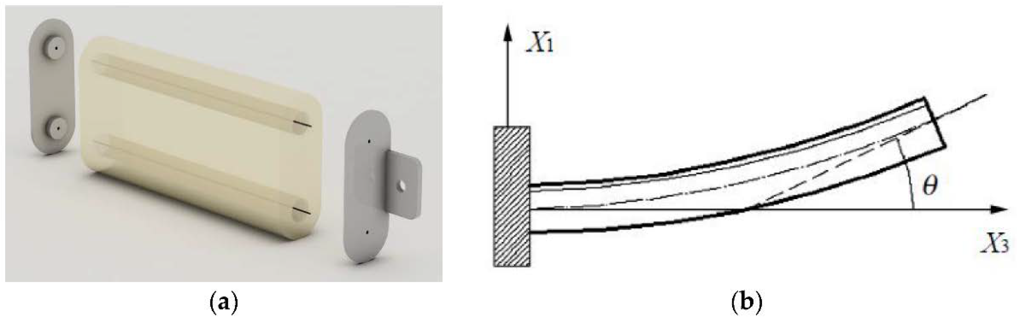
Figure 3.
(a) represents a render of the CPLA component undergoing thermal application measuring its specific levels of thermal energy at different points along it. Where there is a higher thermal measurement at a specific point along the CPLA is represented by the lighter color with red being the hottest, at the point seen it has created a bend in this CPLA material. (b) is what the material actually looks like now as a result of the thermal application due to the concentration of Joule heating (Reprinted with permission from Bai, L. et al. [32]. Copyright 2021, CC BY 4.0 International).
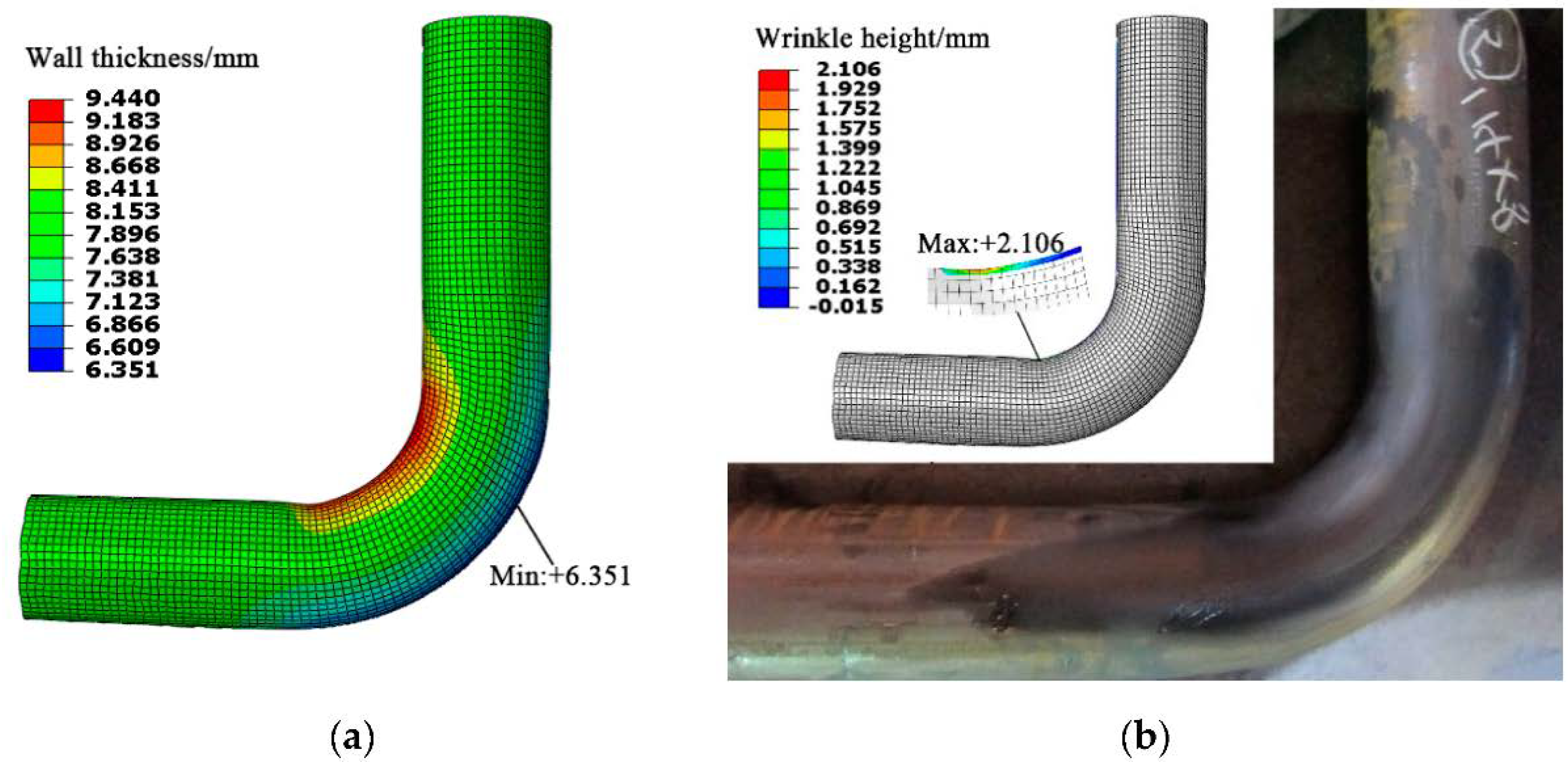
Figure 4.
(a) shows the composition of the hand assembly, which is comprised of a soft layer for the index, thumb, and middle finger. (b) shows the way that the interconnected joints of the finger assembly connect to one another with dovetail anchor plugs and sockets (Reprinted with permission from Zhu, G. et al. [36]. Copyright 2020, CC BY 4.0 International).
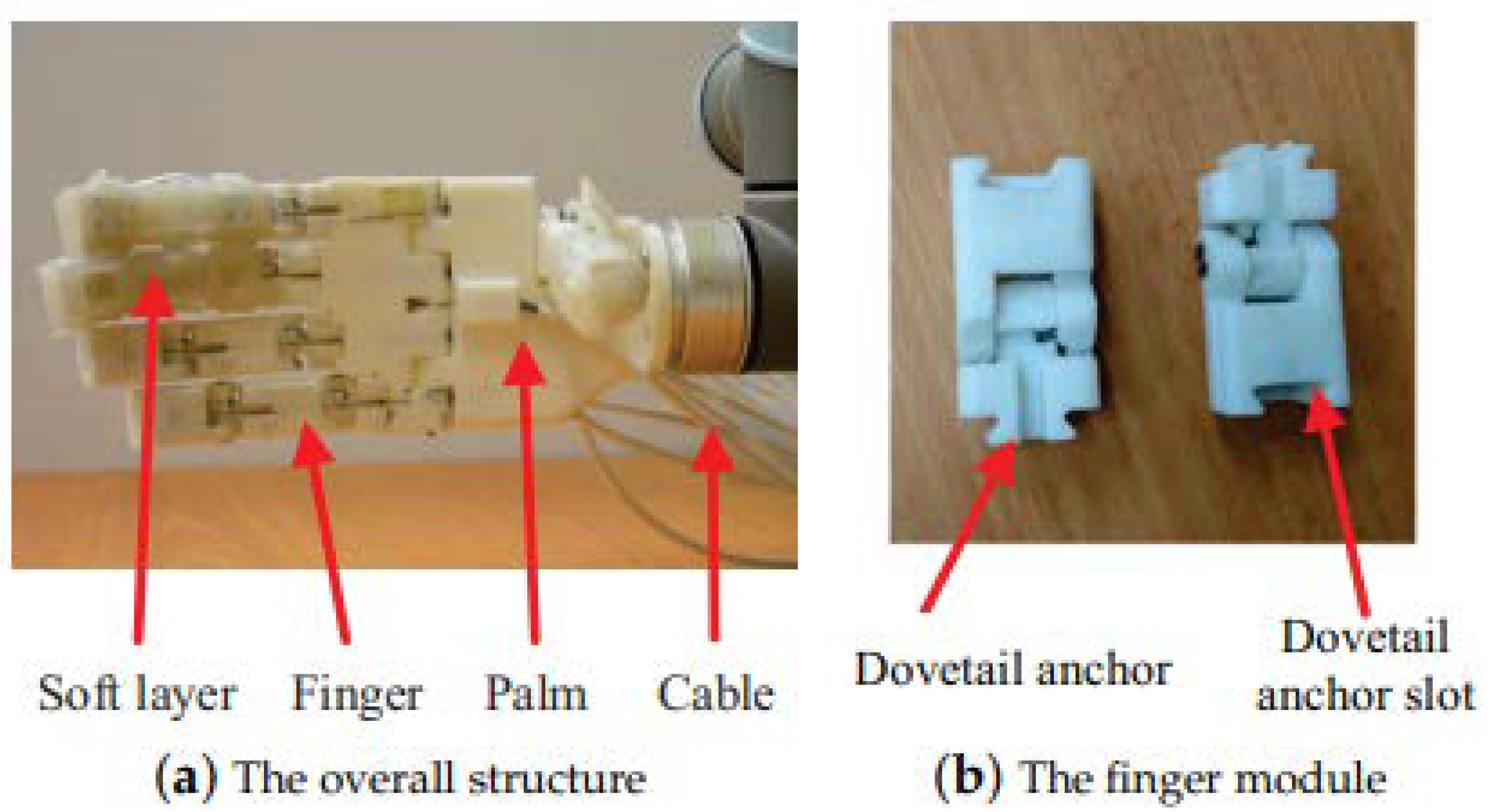
Figure 5.
(a) shows the dimensions as well as a breakdown of this soft layer’s composition. It is comprised of a basic layer, then a spacing layer, followed by the suction layer, and ends with a soft top layer. (b) shows the inflation module in greater detail and with its dimensions, it has a simpler composition of a base and then layers. (c) shows the structure in real time, breaking down where what the suction and inflation modules look like, as well as pointing out the air tubes to allow for the inflation modules’ actuation (Reprinted with permission from Zhu, G. et al. [36]. Copyright 2020, CC BY 4.0 International).

Figure 6.
This shows the teleoperated bimanual assembly carrying a large assortment of different shapes and sizes to show how well it can grip with its soft layer and cumulative hand strength (Reprinted with permission from Zhu, G. et al. [36]. Copyright 2020, CC BY 4.0 International).
Figure 6.
This shows the teleoperated bimanual assembly carrying a large assortment of different shapes and sizes to show how well it can grip with its soft layer and cumulative hand strength (Reprinted with permission from Zhu, G. et al. [36]. Copyright 2020, CC BY 4.0 International).
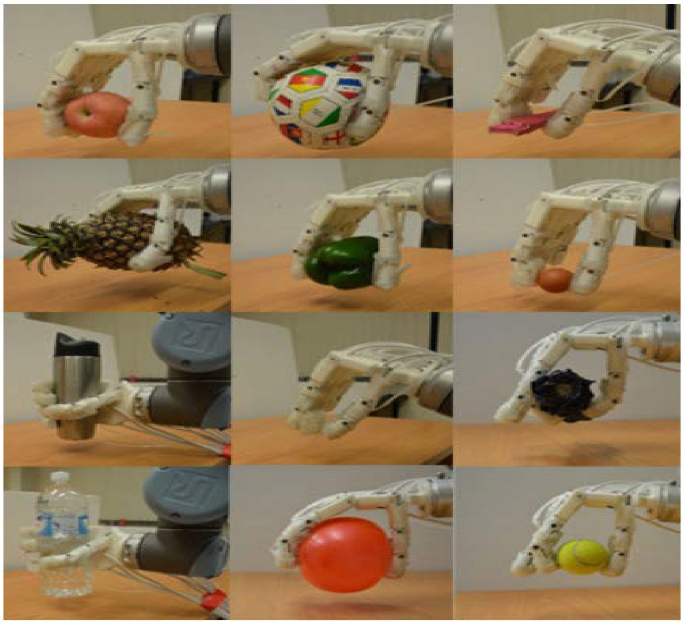
Figure 7.
Fabrication and characterization of graphene fiber artificial muscles, (a) is the scheme of the graphene fiber fabrication; the arrow indicates the direction of rotation; (b) SEM images of the directly dried graphene fiber, and (c) twisted graphene fiber (Reprinted with permission from Foroughi, J. et al. [55]. Copyright 2020, CC BY 4.0 International).

Figure 8.
The image on the left is a three-dimensional model of a single-walled carbon nanotube (SWCNT). The image on the right is three SWCNTs concentrically aligned on top of one another, also known as a multi-walled carbon nanotube (MWCNT) (Reprinted with permission from Ganesh, E.N. [64]. Copyright 2013, CC BY NC ND 4.0 International).

Figure 9.
Fullerene C60 (Reprinted with permission from Mohan, V.B. et al. [50]. Copyright 2018, with permission from Elsevier).
Figure 9.
Fullerene C60 (Reprinted with permission from Mohan, V.B. et al. [50]. Copyright 2018, with permission from Elsevier).
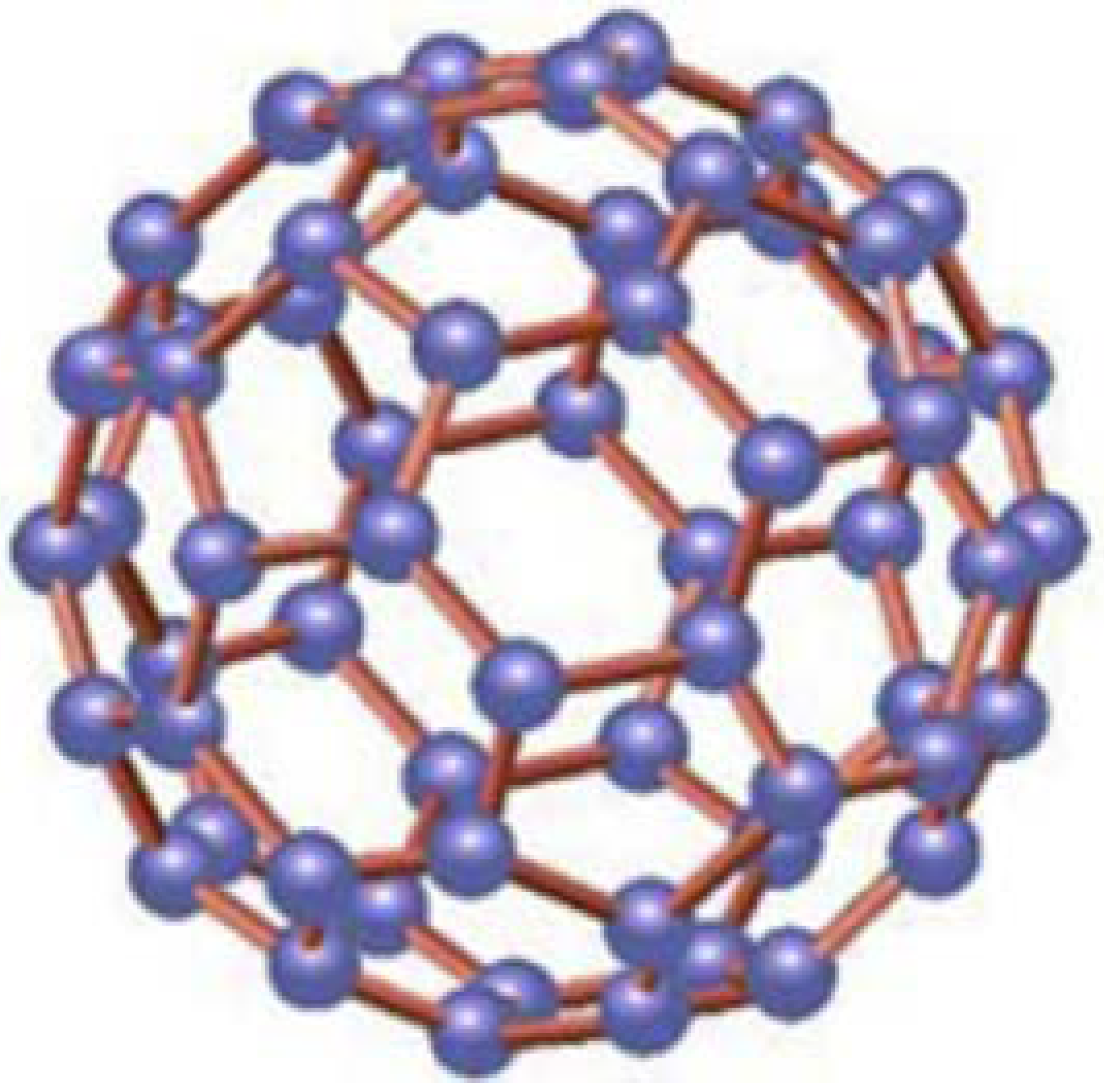
Figure 10.
This is a simplified diagram with brief explanations of each of the molecular robot’s components and how each “robot” interacts with one another (Reprinted with permission from Matsuda, K. et al. [85]. Copyright 2019 American Chemical Society).
Figure 10.
This is a simplified diagram with brief explanations of each of the molecular robot’s components and how each “robot” interacts with one another (Reprinted with permission from Matsuda, K. et al. [85]. Copyright 2019 American Chemical Society).

Figure 11.
Simple McKibben PAM actuation sequence. (a) has the inner sleeve shown at rest with the sleeve and rubber tube holding an inner air tube to feed the air supply into. (b) shows the sleeve becoming pressurized and showing an expansion of the air and rubber tube as well as the sleeve expanding in the radial direction (Reprinted with permission from Peng, Y. et al. [106]. Copyright 2019, with permission from Elsevier).
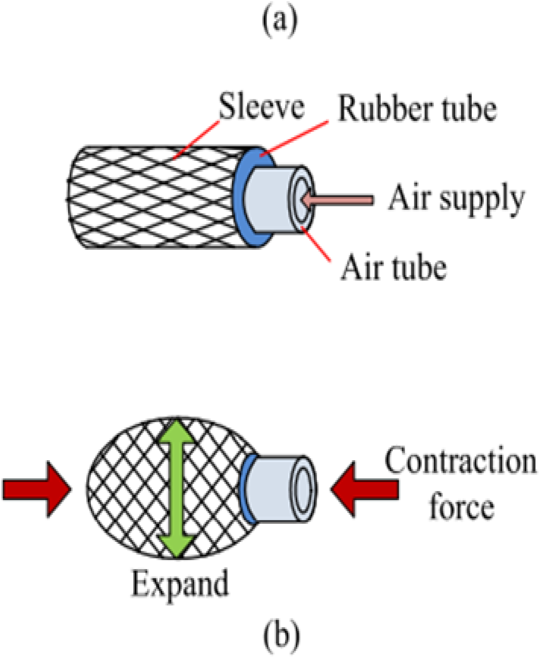
Figure 12.
Origami-inspired vacuum actuator. Found in source [13]. (a,b) illustrate the origami inspiration for the vacuum actuators. (c,d) show the dimensions of the actuator. (e) shows the special change in design for the bending actuator. (f) illustrates the focal point of the buckling action, the blue arrows point toward the direction of the movement towards the focal point. (g,h) show the working action of the twisting-contracting and twisting-bending actuators, respectively (Reprinted with permission from Jiao, Z., et al. [13]. Copyright 2019, CC BY 4.0 International).

Figure 13.
Novel winding artificial muscle driven by pneumatic silicone tubes, (a) shows the tubes at rest in a layout comprised of multiple silicone tubes with the wires sat within the grooves of the tubes. (b) shows the pressurized pneumatic assembly actuating causing the tubes to contract closer to one another (Reprinted with permission from Xie, D. et al. [126]). 2021, CC BY 4.0 International.)
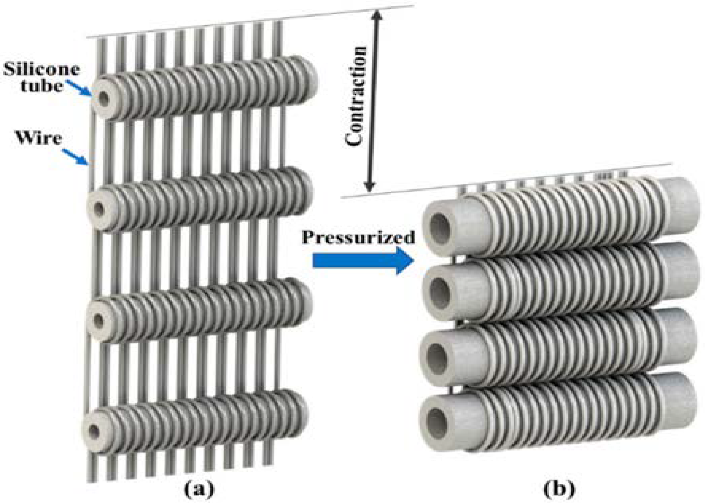
Figure 14.
PAMs with different pressures, where is the muscle length without being pressurized, is the muscle length under pressure, and is the increase in length (Reprinted with permission from Al-Fahaam, H. et al. [112]. Copyright (2018), with permission from Elsevier).
Figure 14.
PAMs with different pressures, where is the muscle length without being pressurized, is the muscle length under pressure, and is the increase in length (Reprinted with permission from Al-Fahaam, H. et al. [112]. Copyright (2018), with permission from Elsevier).

Figure 15.
EBPAM pressurized under different amounts of pressure; increasing from top-left to bottom-right (Reprinted with permission from Al-Fahaam, H., et al. [112]. Copyright (2018), with permission from Elsevier).
Figure 15.
EBPAM pressurized under different amounts of pressure; increasing from top-left to bottom-right (Reprinted with permission from Al-Fahaam, H., et al. [112]. Copyright (2018), with permission from Elsevier).

Figure 16.
A simple TFAM experiencing thermal actuation (Reprinted with permission from Leng, X., et al. [26] Copyright 2020, CC BY NC ND 4.0 International).
Figure 16.
A simple TFAM experiencing thermal actuation (Reprinted with permission from Leng, X., et al. [26] Copyright 2020, CC BY NC ND 4.0 International).
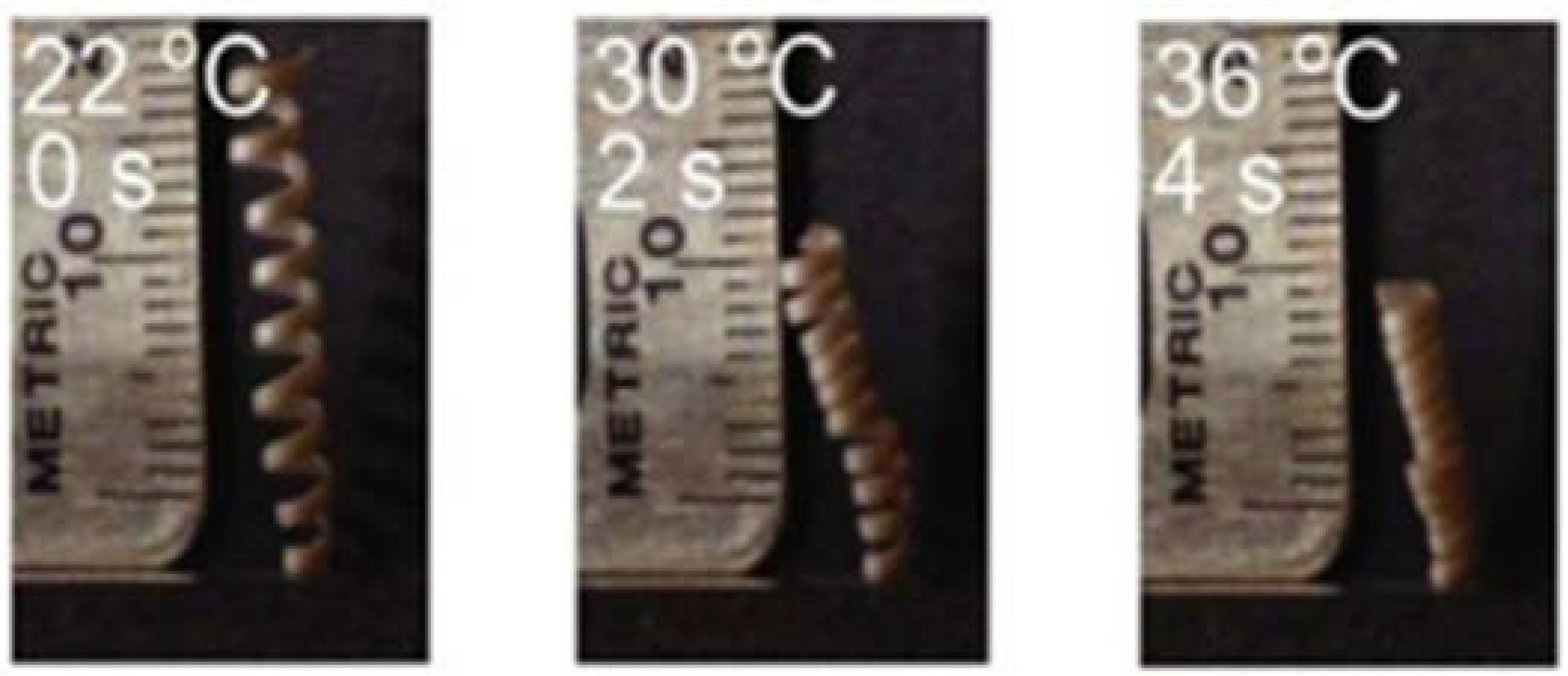
Figure 17.
Three LCEs actuated by electrothermal film in series, these are controlled electronically by running more thermal energy within each of the three sections, (ii) shows the bottom section 3 deforming from being exposed to the electronic external stimuli. (iii) shows another example of actuation after previously deforming the previous section 3 within (ii), in (iii) section portions 3 and 2 have become bent due to the electronic external stimuli. (iv) shows the last example of all three 3, 2, and 1 becoming subjected to the electronic external stimuli and having them all deform as a result (Reprinted with permission from Liu, H., et al. [139]. Copyright 2020, American Chemical Society).
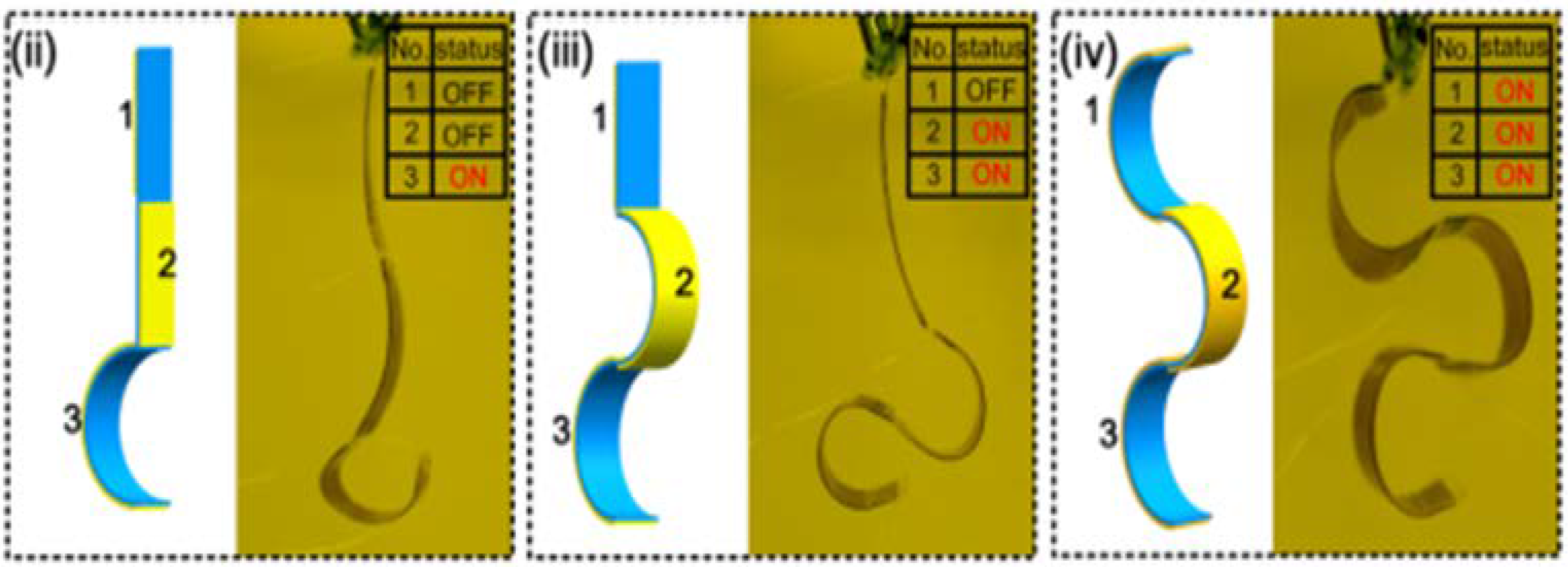
Figure 18.
Diagram of pneumatic artificial muscle with components labeled, D is the width of the overall sleeve assembly, L is the overall length of the assembly, θ is the braided angle (Reprinted with permission from Al-Ibadi, A., et al. [145]. Copyright 2018, CC BY 4.0 International).
Figure 18.
Diagram of pneumatic artificial muscle with components labeled, D is the width of the overall sleeve assembly, L is the overall length of the assembly, θ is the braided angle (Reprinted with permission from Al-Ibadi, A., et al. [145]. Copyright 2018, CC BY 4.0 International).
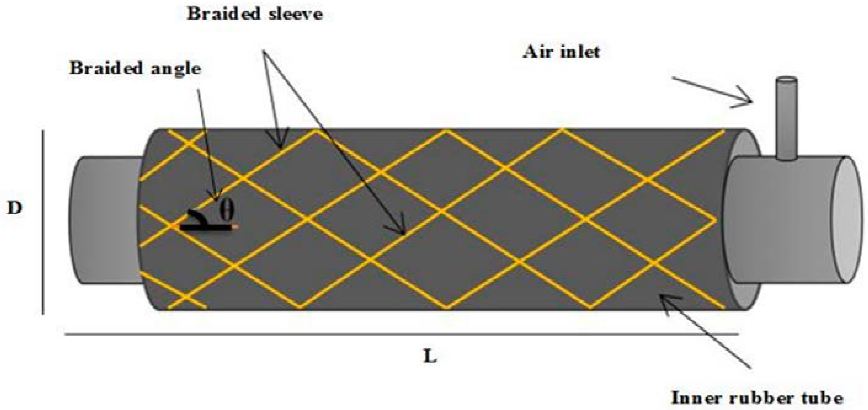
Figure 19.
(a) diagram of the fabrication process of a TCA separated into 4 steps: twist insertion, clamping, annealing, and stretching. (b) Images from an optical microscope of the TCA initial and stretched state (Reprinted with permission from Hwang, I., et al. [147]. Copyright 2022, CC BY 4.0 International).
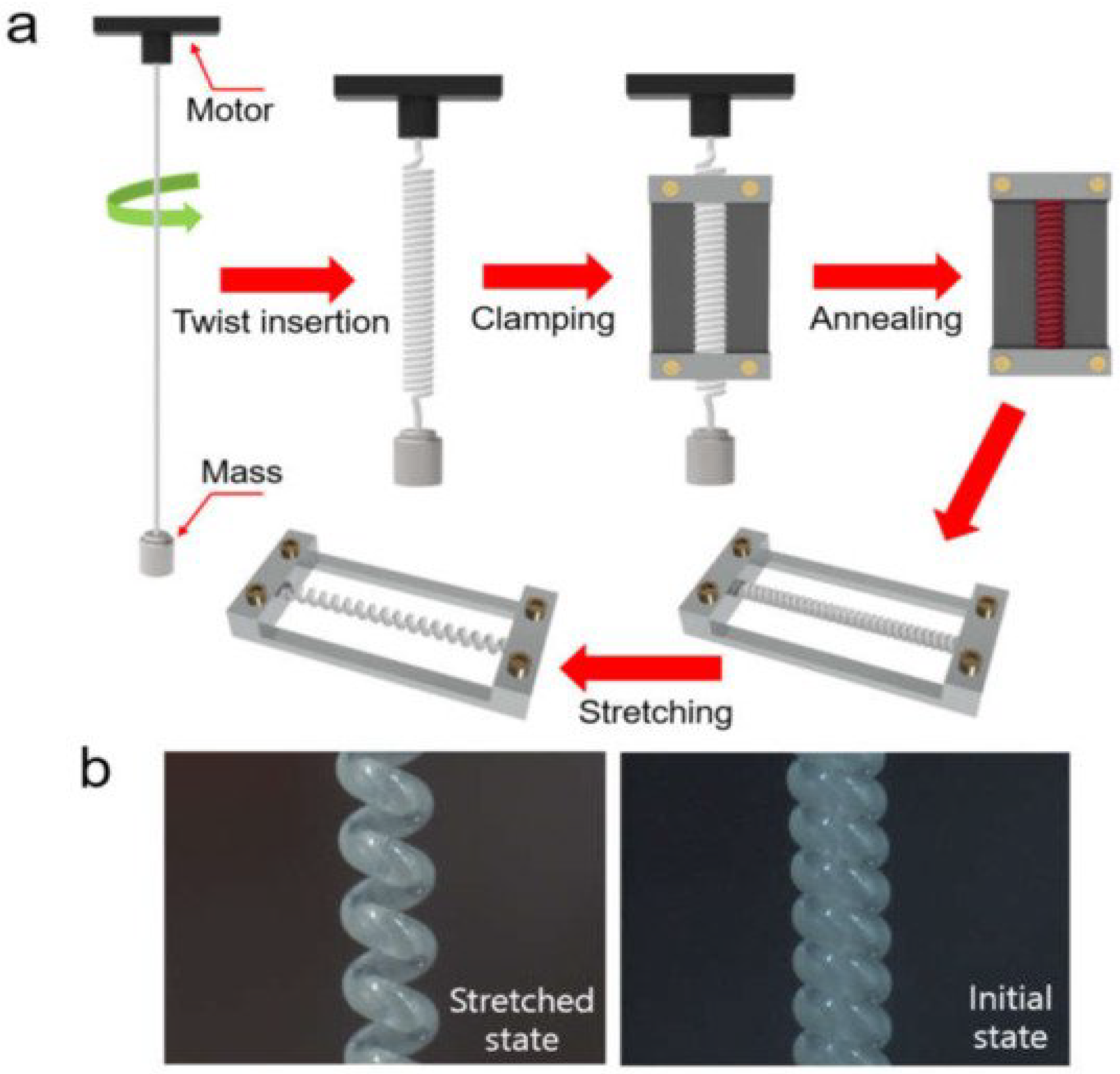
Figure 20.
Diagram outline the programming and transition phases of a two-way shape memory polymer (Reprinted with permission from Scalet, G. [151]. Copyright 2020, CC BY 4.0 International).
Figure 20.
Diagram outline the programming and transition phases of a two-way shape memory polymer (Reprinted with permission from Scalet, G. [151]. Copyright 2020, CC BY 4.0 International).

Figure 21.
Schematic diagram of crystal structure evolution of NiTi SMA tube subjected to stress-induced martensite (SIM) transformation (Reprinted with permission from Jiang, S., et al. [154]. Copyright 2017, CC BY 4.0 International).
Figure 21.
Schematic diagram of crystal structure evolution of NiTi SMA tube subjected to stress-induced martensite (SIM) transformation (Reprinted with permission from Jiang, S., et al. [154]. Copyright 2017, CC BY 4.0 International).

Figure 22.
Brushing method for the stretchable electrode and the fabrication method for a single-layer DEA, (a) shows the first step of laying down the 10 mm square piece of masking sheet that has a hole in the middle of it which is the exposed desired part of the elastomer membrane that will be worked on. (b) shows the pouring of the CNT powder, and (c) shows the use of a brush to prep for spreading the CNT powder across the hole onto the bare elastomer membrane within the hole of the masking sheet. (d) shows the further spreading of the CNT powder across the exposed portion of the elastomer membrane within the masking sheet enough to create a thin layer of CNT across the whole exposed area. (e,f) shows them then pulling off the masking sheet to show the now created concentrated CNT powdered portion now considered an electrode. (g) shows the now formed electrode as result of this concentrated CNT powder on this specific portion of the elastomer membrane (Reprinted with permission from Wiranata, A., et al. [157]. Copyright 2021, CC BY NC ND 4.0 International).
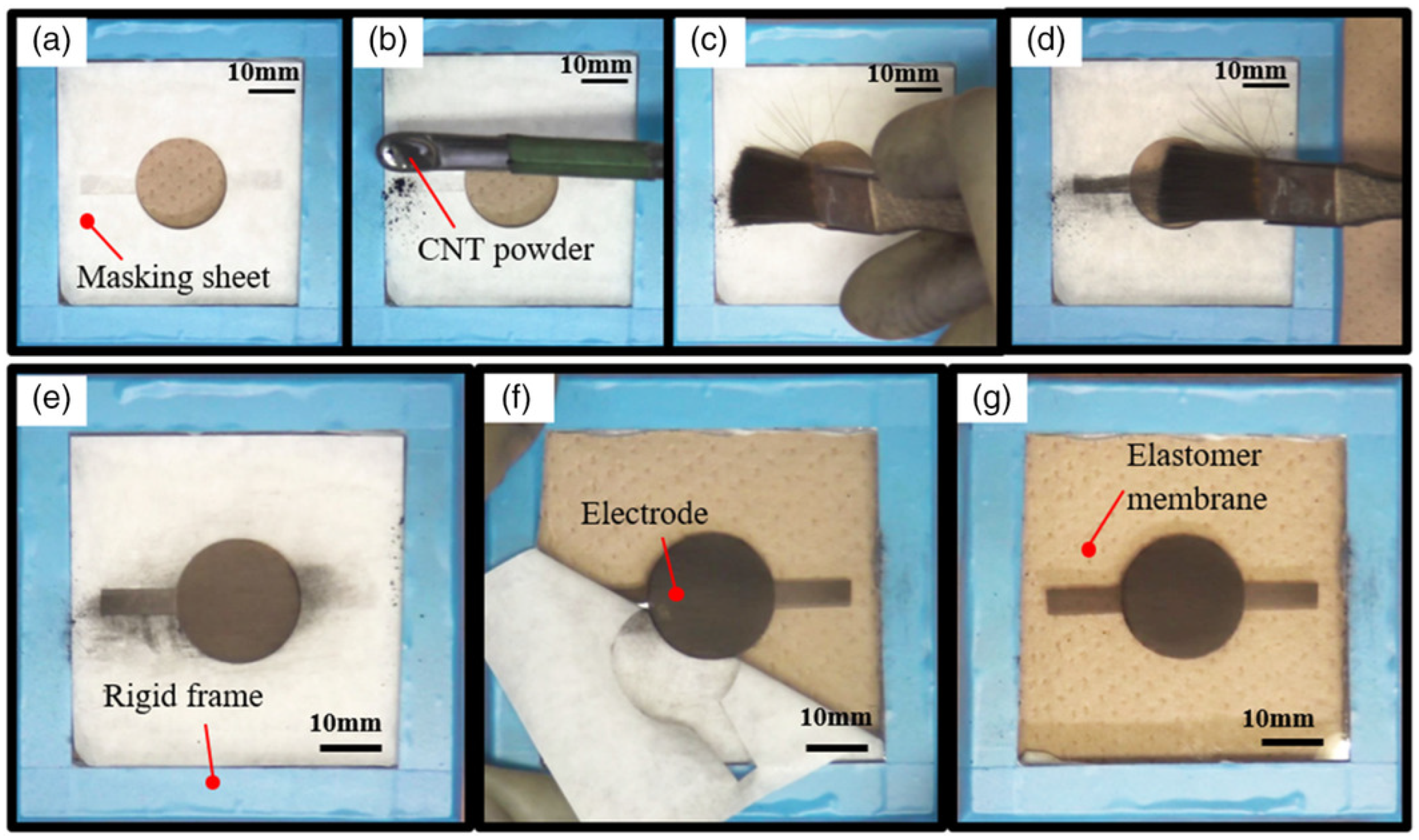
Figure 23.
All scale bars are 5 mm long. (a) Two masks (gray) were used, one for each rubbing direction indicated by blue arrows and gray lines. (b) In the rubbing overwriting method, the entire surface is rubbed in one direction first and one mask is used for the regions with a perpendicular rubbing direction. (c,d) LCE films prepared with the rubbing overwriting technique using: (c) a mask with the University of Warsaw logo cut out and (d) a mask with 1 mm wide slits cut out. The yellow box shows how the accordion-like actuator was cut from the film. White light photographs were taken between crossed polarizers, with the white cross showing the orientation of the polarizers. (e) Accordion-like deformation in a stripe of LCE film cut perpendicular to the pattern lines, heated from 30 °C to 90 °C. (f) Finite element simulation of the LCE stripe deformation. Temperature values relate to conditions in (e,f) (Reprinted with permission from Rogóż, M., et al. [159]. Copyright 2021, CC BY 4.0 International).
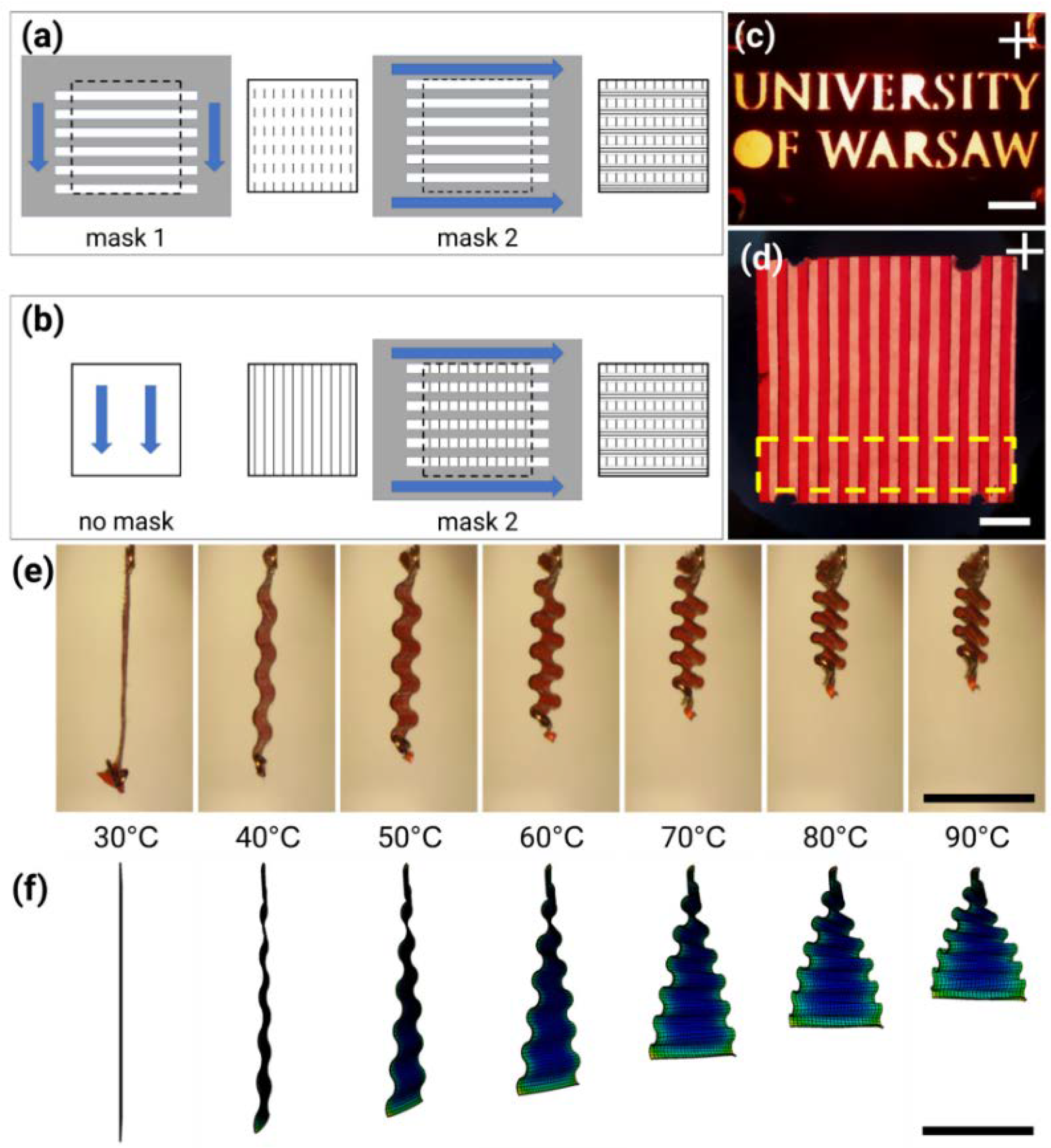
Figure 24.
Diagram of the fabrication of molecular motors (Reprinted with permission from Thai, M.T. et al. [88]. Copyright 2019 American Chemical Society).
Figure 24.
Diagram of the fabrication of molecular motors (Reprinted with permission from Thai, M.T. et al. [88]. Copyright 2019 American Chemical Society).
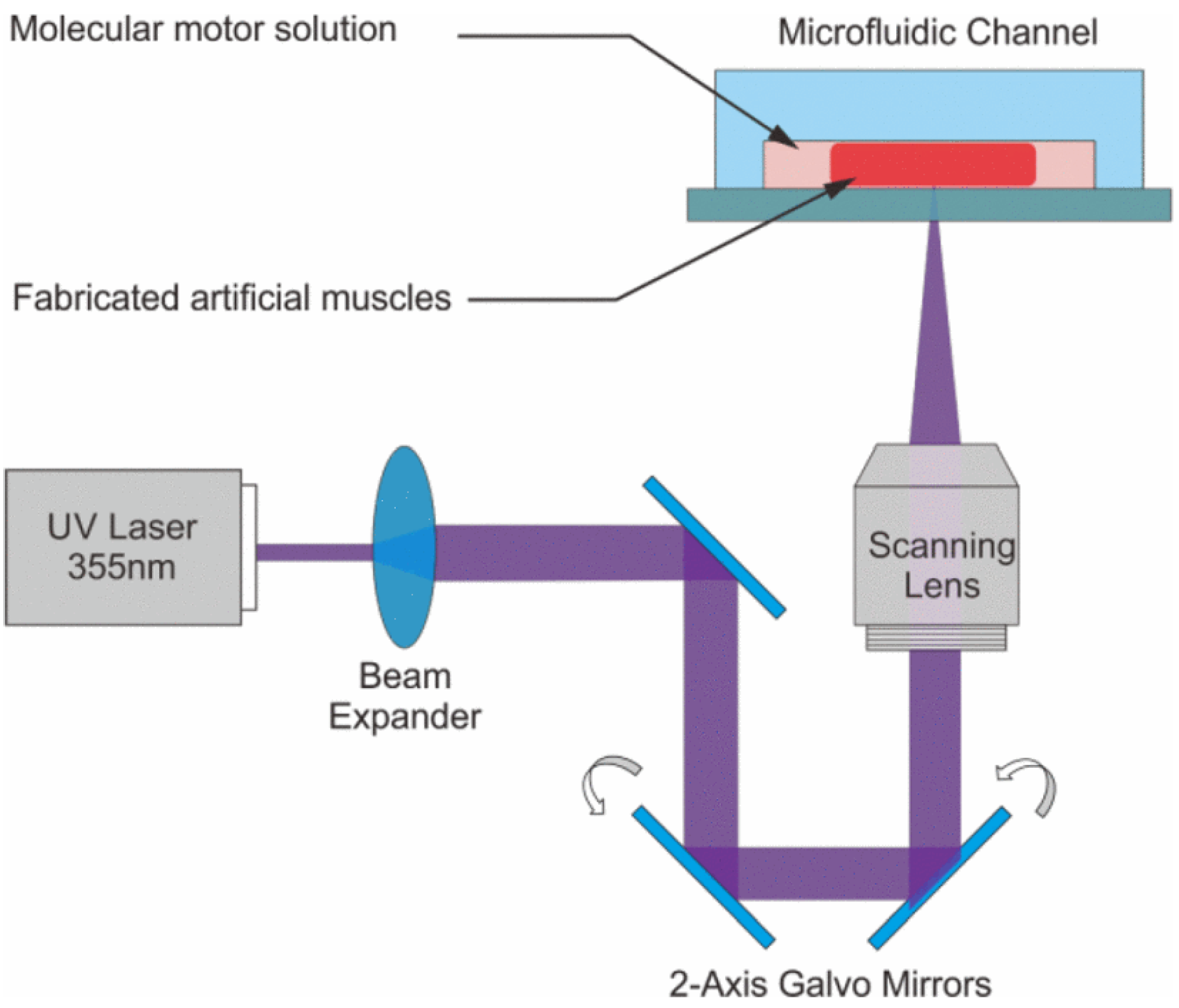

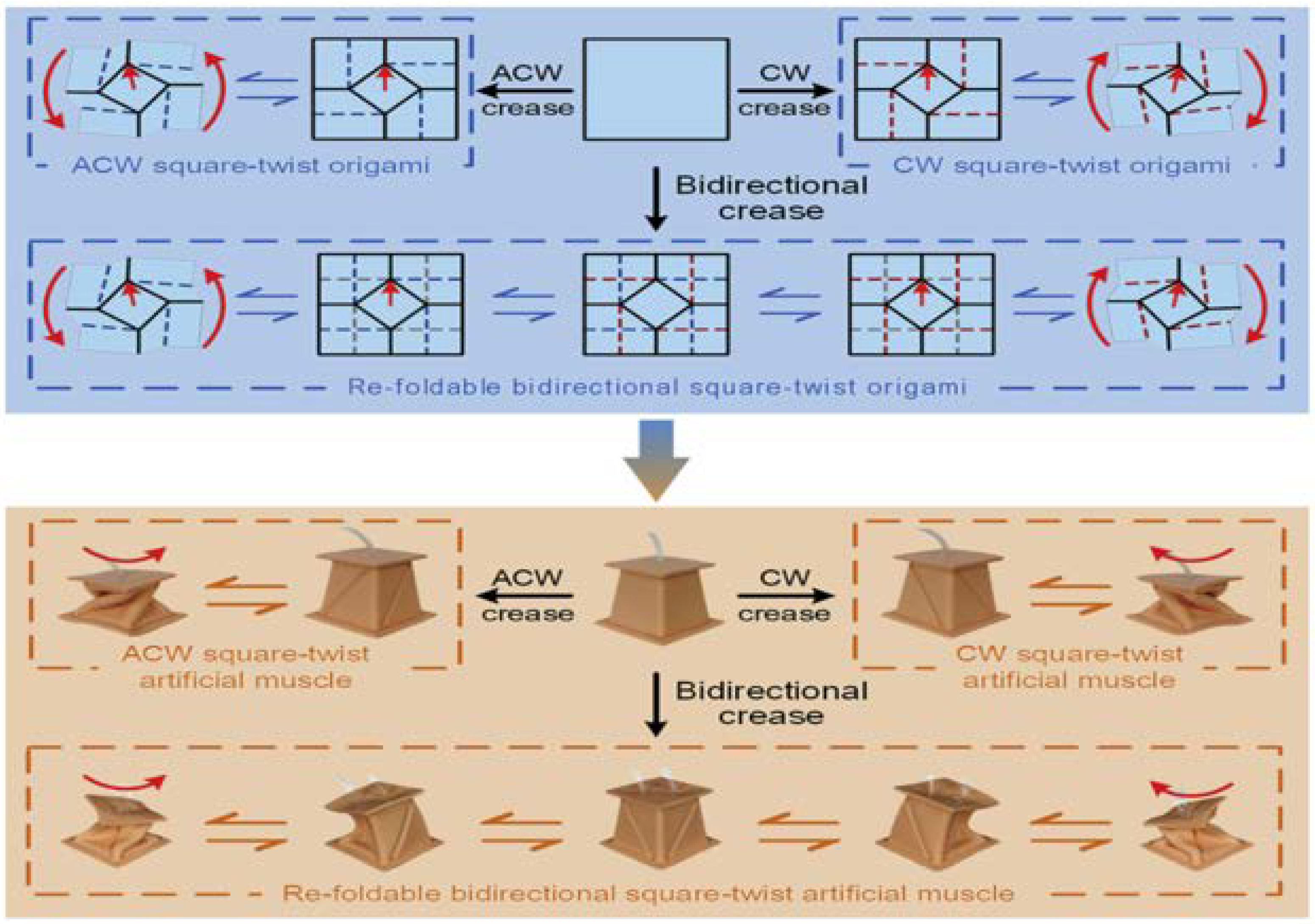
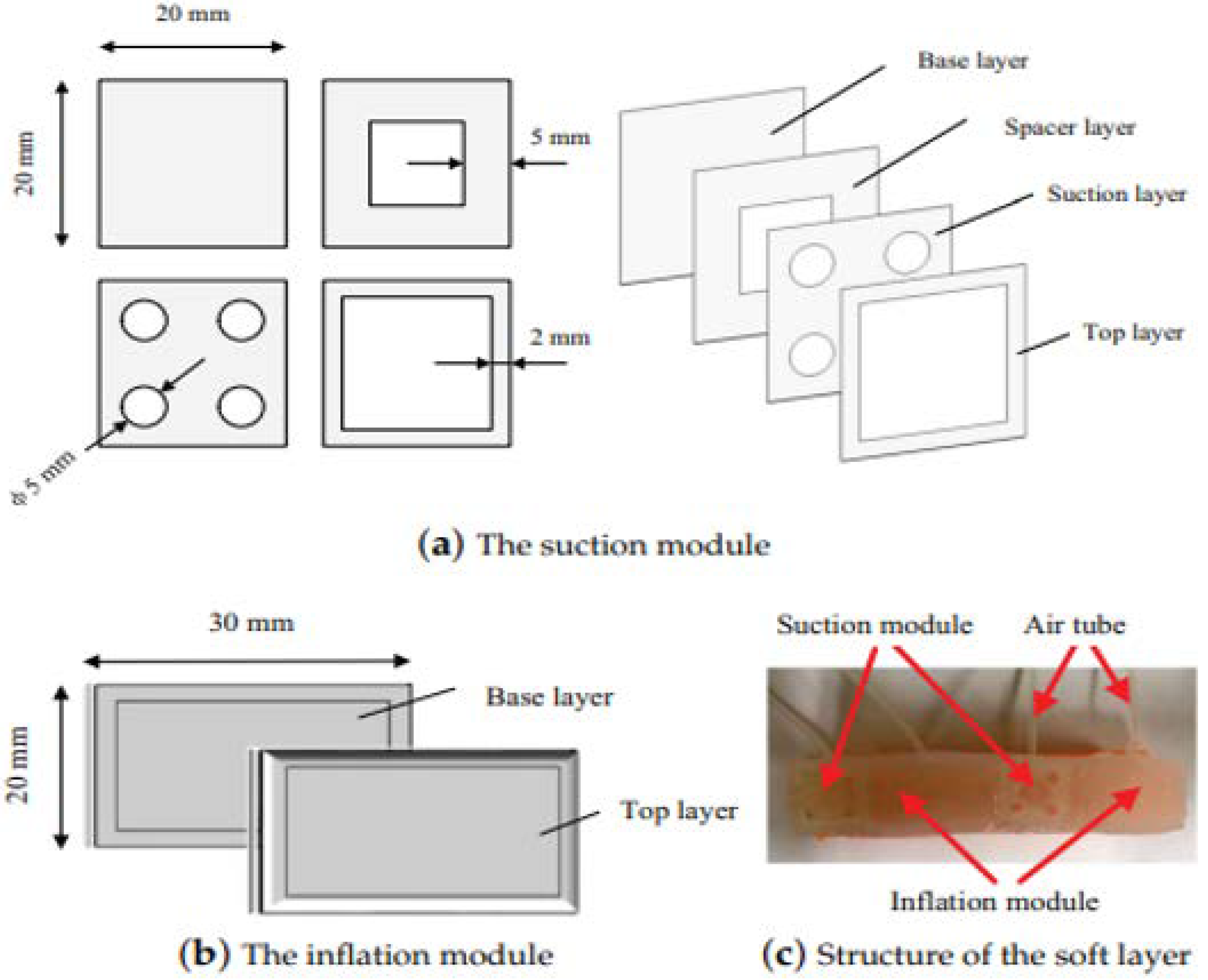
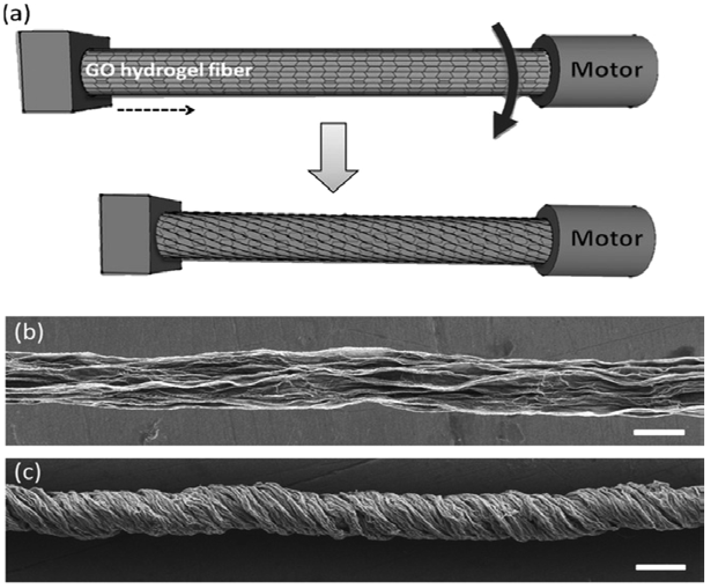
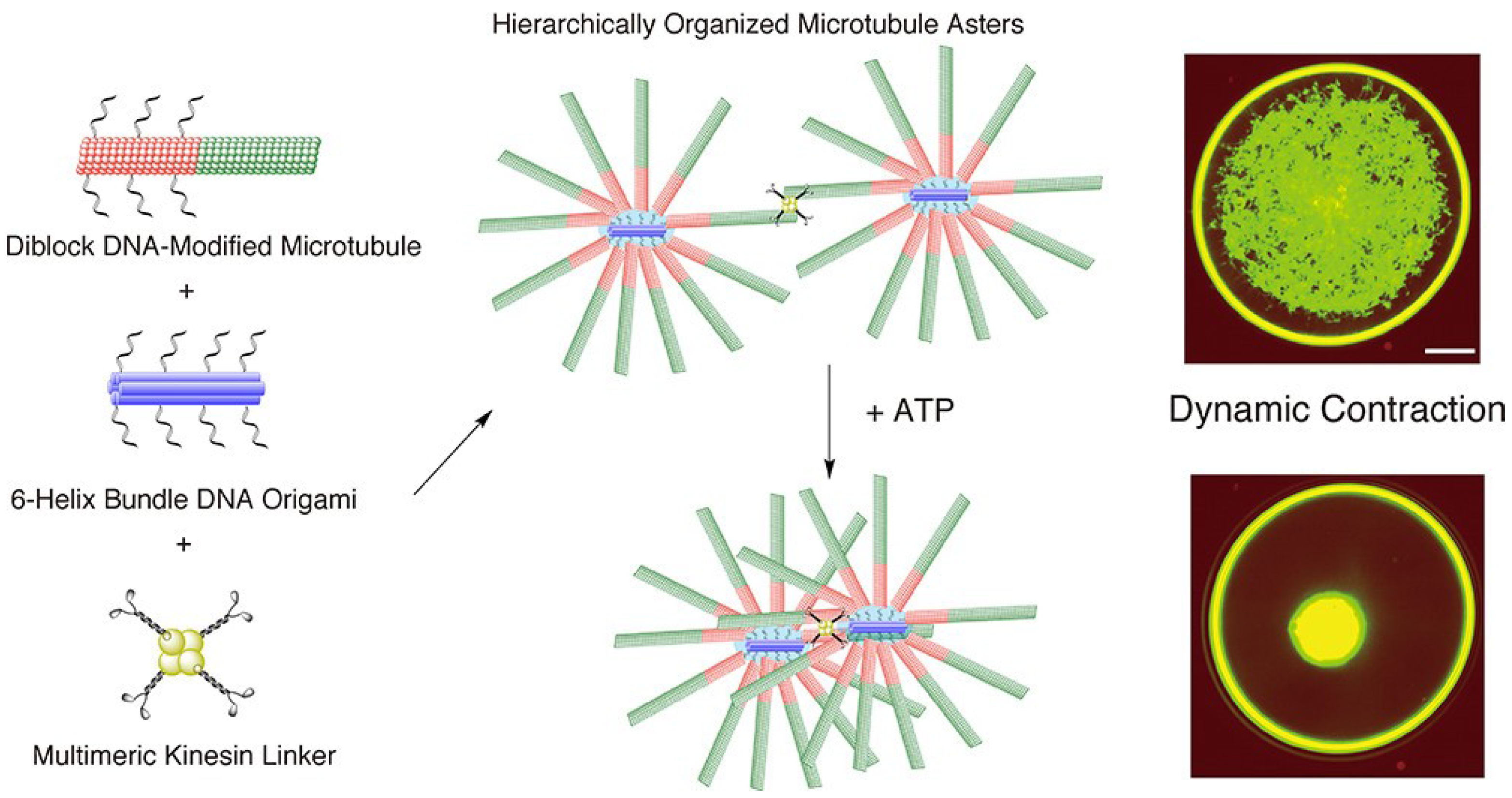
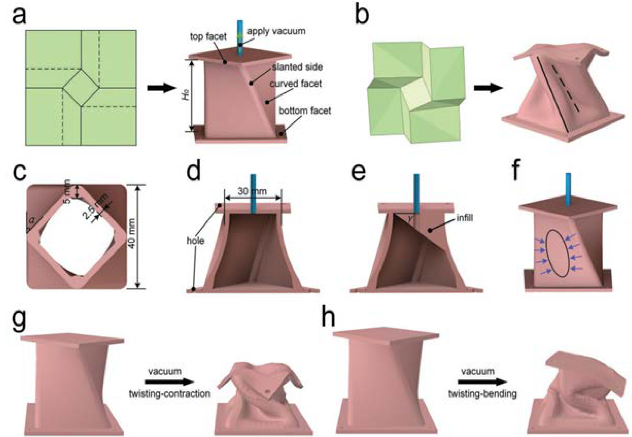
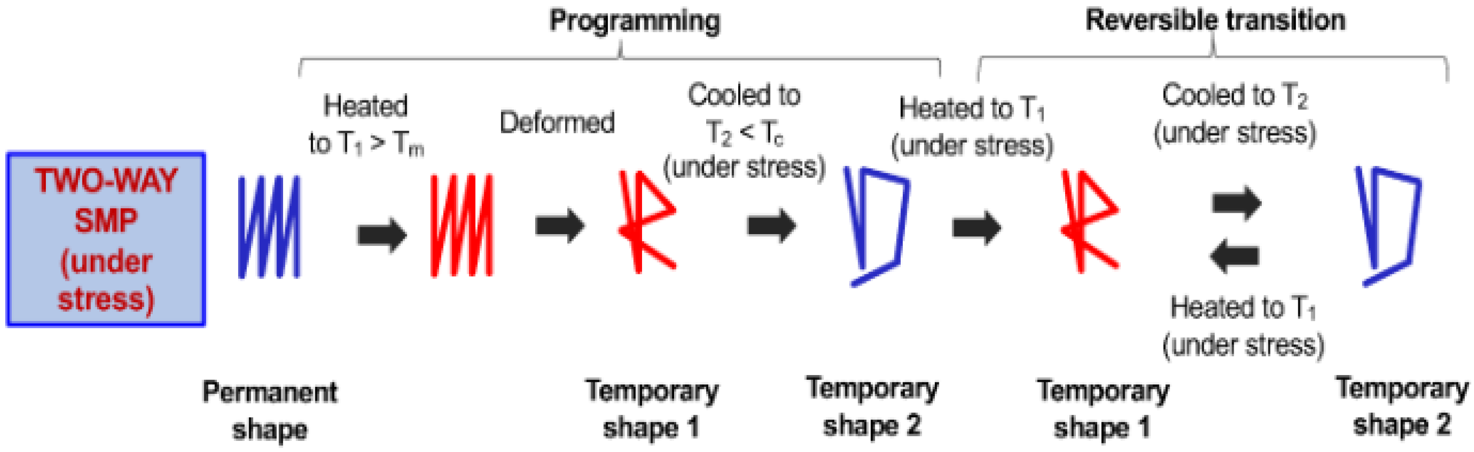
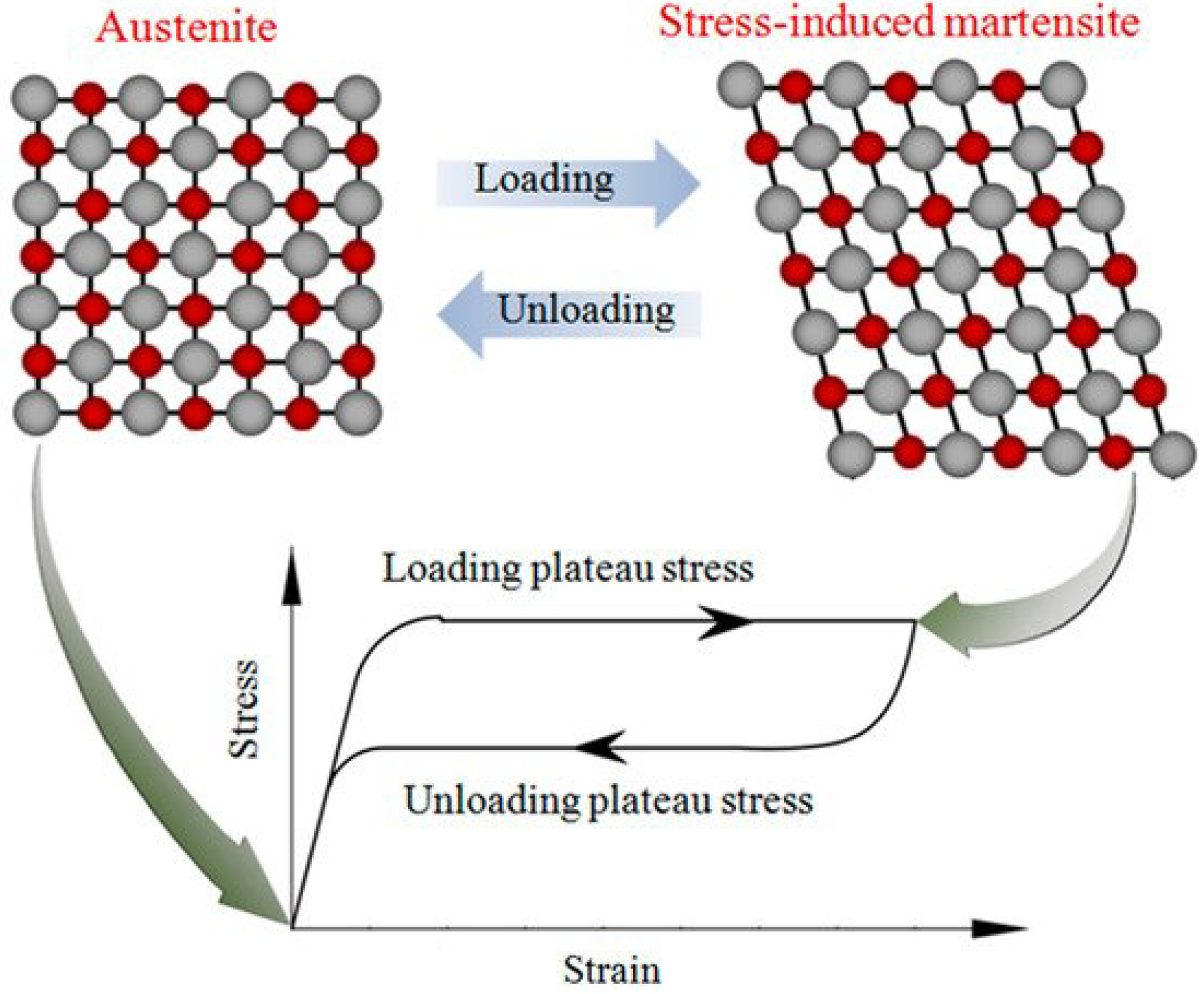
Table 1.
Summary of each category of components and their advantages and disadvantages.
| Type of Component | Advantages | Disadvantages |
|---|---|---|
| Paper-Thin Materials and Techniques for Them [8,10,11,12,13,14,15] |
|
|
| Liquid Crystal Polymers and Elastomers [16,17,18,19,20,46,47] |
|
|
| Artificial Skin and Fabrics [9,21,22,23,24,25,26,27,28,29,48] |
|
|
| Rigid Materials and Techniques for Variability [2,4,8,14,15,24,30,31,32] |
|
|
| Soft Robotic Grippers [4,15,33,34,35,36] |
|
|
| Soft Robotic Sensors [16,31,36,37,38,39,40,41,42] |
|
|
| Miscellaneous Techniques for Materials Used in Actuation [43,44,45] |
|
|
Table 2.
Mechanical properties of nanocomponents.
| Material | Diameter (nm) | Length (nm) | Young’s Modulus (GPa) | Tensile Strength (GPa) | Thermal Conductivity (W/mK) | Electrical Conductivity |
|---|---|---|---|---|---|---|
| Graphene [93,94,95,96,97] | 0.34 nm | — | 1000–1300 | 130 | 3000–5000 | Up to 108 S/m |
| Single-Wall Carbon Nanotubes [96,98] | 1–2 nm | 100–1000 mn | 100–1000 | 22.2 ± 2.2 | 3000–6000 | Up to 107 S/m |
| Multi-Walled Carbon Nanotube [98] | 5–100 nm | Up to 15,000 nm in length | 300–1000 | 11–63 | 2000–3000 | — |
| Fullerene (C60) [99,100] | 1.1 nm | — | 1.09 ± 0.08 | 45 ± 1.5 | 0.4 | — |
| Gold Nanoparticles [101,102,103,104] | 1–100 nm | — | 79 | 1.8 | 318 | 106 S/m |
| Silver Nanoparticles [90,104] | 1–100 m | — | 83 | 0.14 | 429 | 105 S/m |
Table 3.
Summary of micro and nano materials and components.
| Type of Nano Component | Advantages | Disadvantages |
|---|---|---|
| Graphene [50,51,52,53,54,55,56,57,58,59,60,61,62,63,99,100] |
|
|
| Carbon Nanotubes (CNTs) [28,29,62,63,64,65,66,67,68,69,70,71,72,73,74] |
|
|
| Fullerene [21,75,76,77,78,79,80,81,82,83] |
|
|
| Gold Nanoparticles [102,103,104] |
|
|
| Silver Nanoparticles [90,104] |
|
|
| Molecular Motor [2,79,84,85,86,87,88] |
|
|
Table 4.
Summary of each actuation category’s advantages and disadvantages.
| Actuation Method | Advantages | Disadvantages |
|---|---|---|
| Pneumatic [1,2,4,13,33,35,48,65,105,106,107,108,111,112,113,114,115,116,117,118,119,120,121,122,123,124,125,126] |
|
|
| Vacuum [61,121,143] |
|
|
| Hydraulic [34,88,128] |
|
|
| Twisted Fiber [11,26,27,28,29,39,120,128,129,130,131,132] |
|
|
| Shape Memory Polymers and Alloys [8,9,109,133,134,135] |
|
|
| Electroactive Materials [27,110,136,137,138] |
|
|
| Liquid Crystal Elastomer [18,139] |
|
|
Table 5.
Fabrication summary table.
| Fabrication Process | Simplified Explanation |
|---|---|
| Pneumatic [144,145] | K-PAM
|
| Hydraulic [146] | McKibben
|
| Twist Fibers [26,147,148] | Sun et al., TCA Fabrication
|
| Ionic Polymers [149] | Impregnation electroplating
|
| Shape Memory Polymers [150,151] | Two-Way SMP (Under Stress)
|
| Shape Memory Alloys [152,153,154,155] | Powder metallurgy
|
| Dielectric Elastomer [156,157] | Brushing Method for Single-Layer DEA
|
| Liquid Crystal Elastomer [158,159] | Rubbing Overwriting
|
| Graphene [160,161] | Roll to Roll Milling
|
| Carbon Nanotubes [98] | Arc Discharge Technique
|
| Fullerene [146,162] | Liquid-to-Liquid Interfacial Precipitation Method
|
Publisher’s Note: MDPI stays neutral with regard to jurisdictional claims in published maps and institutional affiliations. |
© 2022 by the authors. Licensee MDPI, Basel, Switzerland. This article is an open access article distributed under the terms and conditions of the Creative Commons Attribution (CC BY) license (https://creativecommons.org/licenses/by/4.0/).
Share and Cite
MDPI and ACS Style
Craddock, M.; Augustine, E.; Konerman, S.; Shin, M. Biorobotics: An Overview of Recent Innovations in Artificial Muscles. Actuators 2022, 11, 168. https://doi.org/10.3390/act11060168
AMA Style
Craddock M, Augustine E, Konerman S, Shin M. Biorobotics: An Overview of Recent Innovations in Artificial Muscles. Actuators. 2022; 11(6):168. https://doi.org/10.3390/act11060168
Chicago/Turabian StyleCraddock, Matthew, Emmanuel Augustine, Sam Konerman, and Minchul Shin. 2022. "Biorobotics: An Overview of Recent Innovations in Artificial Muscles" Actuators 11, no. 6: 168. https://doi.org/10.3390/act11060168
Note that from the first issue of 2016, this journal uses article numbers instead of page numbers. See further details here.