
Stabilization of a Magnetic Repulsive Levitation Flywheel System Using a High-Efficiency Superconducting Magnetic Bearing

Division of Mechanical Science and Technology, Gunma University, 1-5-1 Tenjin, Kiryu 376-8515, Japan
*
Author to whom correspondence should be addressed.
Actuators 2022, 11(7), 180; https://doi.org/10.3390/act11070180
Submission received: 20 April 2022
/
Revised: 24 June 2022
/
Accepted: 26 June 2022
/
Published: 29 June 2022
(This article belongs to the Special Issue Advanced Technologies in Superconducting Actuators)
Abstract
:In this study, we developed a superconducting magnetic bearing using a permanent repulsive magnet. A repulsive magnetic levitation system with a permanent magnet can generate a strong levitation force in the absence of a power supply. However, it is unstable, except in the direction of repulsion. In contrast, superconducting magnetic bearings can generate a restoring force in all directions by utilizing the magnetic flux pinning property of the superconductors. Therefore, we constructed a superconducting magnetic bearing (SMB), which is stable along all axes without control, and has a strong axial levitation force, by combining a repulsive-type magnetic levitation system and a superconducting magnetic levitation system. We also reduced the amount of HTS used for the SMB and proposed an efficient method of using HTS. Furthermore, a driving test of the flywheel incorporating the SMB was conducted to verify the characteristics of the SMB. The experiment confirmed that the flywheel could overcome the resonance and drive the flywheel. In the drive experiment, the flywheel was driven up to 10,000 rpm.
1. Introduction
The superconducting magnetic bearing (SMB) used for magnetic levitation flywheels utilizes the fact that a magnet can be constrained in a noncontact manner in space by magnetic flux pinning, which is one of the characteristics of the second type of superconductor [1,2,3,4]. Rotational loss occurs in bearings, such as metal bearings and rolling bearings, which are subject to contact, and when used for a long time, their function is deteriorated by abrasion. The SMB generates a restoring force along all axes without the necessity of control; it is not necessary to lubricate it, and the rolling loss can be made extremely low [5]. Furthermore, it is possible to realize a bearing with a high rigidity only in a specific direction and a soft bearing in another direction. Therefore, it is suitable for high-speed rotations and is expected to have a semi-permanent life. Due to these features, research has been conducted on the storage of electricity using the flywheel of a high-temperature superconducting levitation motor and a centrifugal separator [6,7].
However, the basic structure comprising high-temperature superconducting magnetic levitation is almost identical in these studies. The method is to allow a high magnetic flux density field created by a permanent magnet, or etc., to penetrate the high-temperature superconductor (HTS) bulk. As mentioned above, there has been little research on the efficient use of HTS in superconducting magnetic levitation systems.
Therefore, previously, this research team proposed a new field structure and proposed a high-density field section with permanent magnets. This method was used in an SMB supporting repulsive magnetic levitation [8], where the main axial restoring force was the flux pinning force of the superconductor.
Here, considering the case of supporting a load using axial gravity using passive magnetic bearings with permanent magnets for use in the bearings of a flywheel, the suction type is stable, because the restoring force constantly acts in the direction perpendicular to the suction direction. However, considering the repulsive type, the repulsive force becomes stronger as the repulsion direction is approached. Therefore, it is stable in the repulsion direction, but in the direction orthogonal to the repulsion direction, including pitching, it is unstable. However, if this unstable force can be canceled in some way, a strong restoring force can be obtained by the strong magnetic force from a rare-earth magnet without a power supply.
Therefore, in this study, we take advantage of the permanent strong levitation force of a repulsion levitation system without a power supply using a permanent magnet and make use of the repulsive force of the permanent magnet for the axial levitation force required in the flying of a flywheel. We aim to stabilize only the radial instability generated by a magnet and the flux pinning of the superconductor. In this way, SMBs with reduced use of HTS can be achieved, thus enabling smaller bearings with the same performance and the reduced costs of HTS and cooling. Therefore, it is a very significant study.
We measured the restoring forces in the radial, axial, and pitching directions of the produced magnetic bearings and verified the usefulness of the SMB stabilization method for the repulsive magnetic levitation system proposed in this research.
In addition, we fabricated a flywheel, incorporating the bearing part we made, and confirmed the usefulness of the SMB manufactured with a driving experiment.
2. Development of Superconducting Magnetic Bearing (SMB)
2.1. Configuration of SMB
As shown in Figure 1, a ring magnet magnetized in the radial direction is realized in a pseudo manner by adopting a configuration in which a segment-type magnet, magnetized at the rotor side, is combined with a ferrous iron pipe-type part. This uses 16 segmented magnets with outer N-pole magnetization, a pipe-shaped iron plate, and 16 segmented magnets with outer S-pole magnetization.
In this configuration, there are two magnetic flux converging parts in the cross-section, and when the PM is displaced in the radial direction (horizontal direction), the direction and strength of the magnetic flux entering the high-temperature superconductor (HTS) significantly changes. Therefore, we believe that the restoring force in the radial direction can be improved.
To further strengthen the magnetic flux pinning by utilizing the upper field magnet portion of such a structure, we also decided to utilize HTS. By doing this, a magnetic circuit is created by the two focused magnetic fluxes, and this magnetic flux penetrates the HTS, so a strong pinning force is expected.
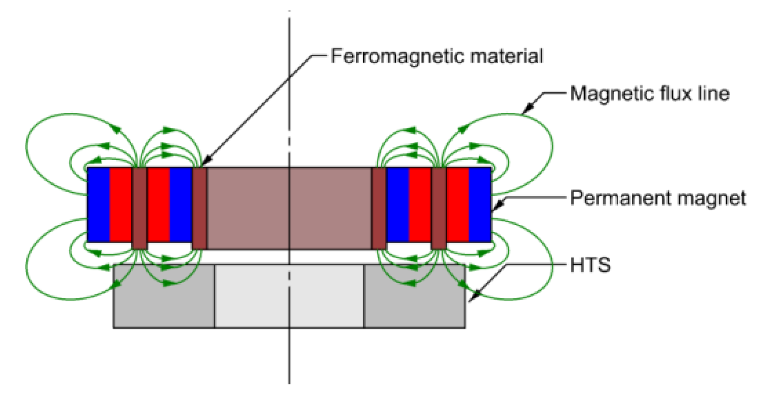
Figure 2 shows the SMB structure used in this research, combining the axial flux convergence part for HTS pinning, the radial flux convergence part, and the levitation force generation repulsion magnet part. The magnetic flux converging part is constituted by arranging the same poles as in the ring-type permanent magnet, with the thicker direction of magnetization facing each other and sandwiching the ferromagnetic ring-shaped disc. Therefore, a strong magnetic flux density was generated in the radial direction at the side surface. Then, in order to generate an axial restoring force to support the gravity acting on the flywheel, the arrangement of the ring-type permanent magnet on the rotor side has to be the same as that on the stator side, so as to repel the lower side, i.e., the magnetic repulsive portion.
The repulsive force of this permanent magnet also works in the radial direction, so it becomes unstable in the radial direction. This repulsive force is thought to increase in inverse proportion to the square of the distance between the permanent magnets. By finely adjusting the distances of the permanent magnet repulsion parts, the radial unstable force can be restrained by the binding force of the superconductor, such that it is within the range that can be stabilized.
2.2. Specifications of Superconductor
3. Development of Superconducting Magnetic Bearing (SMB)
3.1. Magnetic Flux Density Distribution Generated by the SMB Rotor Section
As mentioned above, in this study, the magnetic arrangement of the SMB rotor section is formed by combining a pipe-type ferromagnetic body and a segment-type magnet with radial magnetization to generate a large magnetic flux density gradient in the radial direction. In the magnetic flux converging part, a thin ferromagnetic substance plate is sandwiched between the segment of the magnet with the N pole on the radial outer side and that with the N pole on the inside. The ferromagnetic plate is strongly magnetized, so that a magnet is created because of the synergistic effects with the magnetic field, and a high magnetic flux density is generated at the end face of the ferromagnetic material.
The magnetic flux density distribution generated on the HTS surface by this structure was confirmed by simulations using electromagnetic analysis software and by manufacturing the rotor part and measuring the magnetic flux density.
3.1.1. Simulation of the Magnetic Flux Density
In this study, we simulated the magnetic flux density distribution generated by the SMB permanent magnet using the electromagnetic analysis software JMAG and the finite element method. The model used for the simulation is shown in Figure 4. The simulation conditions are presented in Table 2.
The graph of the magnetic flux density on the upper surface of the HTS was plotted at a distance from the lower end of the rotor section of between 1 and 6 mm. The plotting section line was set at the position shown by the yellow line in Figure 5a. Similarly, a graph of the magnetic flux density on the side of the HTS was plotted for R = 22–26 mm from the rotation axis. The position at which the magnetic flux density on the side surface of the HTS was plotted was set to the yellow line in Figure 5b.
3.1.2. Measurement of Magnetic Flux Density
The rotor part was fixed in the state of being turned upside down, and a magnetic flux density measuring probe with a Hall element was used. This was fixed by moving it onto the linear stage. Depending on the structure of the magnetic flux density measuring probe, there are sections that, although plotted in the simulation, cannot be measured. The measurement device for magnetic flux density was tesla meter (TM-801; KANETEC Co., Ltd., Nagano, Japan), and the measurement error was
A graph obtained by plotting the results of the measurements of the magnetic flux density and the simulation result are shown below. A graph of the radial component of the upper surface of the HTS is shown in Figure 6a and a graph of the axial direction component is shown in Figure 6b. A graph of the radial component of the HTS side is shown in Figure 7a, and a graph of the axial component is shown in Figure 7b. Because there is no repulsive permanent magnet on the stator side at the time of measurement, the results are slightly different from the simulation results described in the previous section.
For the radial direction component of the measurement results on the HTS top surface, the simulation and measurement results were almost same. For the axial direction component, the measurement result was slightly smaller toward the negative side than the simulation result. For the radial direction component of the measurement results on the HTS side, the measurement result appears to be at a position of −12 mm compared with the simulation result, but the magnitudes almost match. Regarding the axial direction component, the measurement result gradually becomes smaller than the simulation result, with the distance to the lower part of the rotor decreasing.
Possible causes for these deviations are that the size of the segment magnet is somewhat small, that the strength of the remnant magnetization of the ring magnet is different from that in the simulation, there is a dimensional error in the SMB assembly, etc. Based on the magnitude criterion of the magnetic flux density, the error was approximately 7% at its peak, and it was determined that the magnetic flux density distribution obtained was almost the same as the simulation result.
Subsequently, to ascertain the extent of the fluctuations in the magnetic flux density in the circumferential direction caused by the segment-type magnet, which results in the rotational resistance in the SMB, the rotor section was mounted on a jig with ball bearings, and the magnetic flux density was measured while rotating the rotor section. The distance from the rotor section to the measurement position was 2 mm.
A graph of the circumferential variation in the radial component of the magnetic flux density is shown in Figure 8a, and a graph of the circumferential variation in the axial component of the magnetic flux density is shown in Figure 8b.
From the measurement results, the variation in the radial direction was approximately 20 mT at R = 23 mm and 10 mT at R = 23 mm. The magnetic flux density fluctuations per unit of rotation are considered to be due to the effect of measuring while rotating.
The magnetic flux density fluctuations over 16 periods by the segment magnet were slightly larger than those in the simulation result. This is because the size of the segment magnets was slightly smaller in the angular direction than at the time of design; therefore, it is thought that there was a formation of gaps between the segment magnets. However, because this fluctuation is not as large as the magnitude of the magnetic flux density of the converging magnetic flux portion, the fluctuation in the magnetic flux density in the circumferential direction does not significantly affect the rotational resistance of the SMB. In Figure 8, in the radial direction component, a prominent waveform can be observed, with a median value of approximately 100 mT at R = 23 mm. Such fluctuations in the magnetic flux density are considered to be due to the rotational resistance of the magnetic bearing, as mentioned above. However, as it is a radial component and the median value is not very large, it is not considered to be a significant rotational resistance. For this reason, it was assumed that there would be no problems with its use in this study.
3.2. Restoring Force Generated by SMB
First, for the manufactured SMB, the radial restoring force was measured to confirm that the radial instability due to the repulsive magnet could be stabilized by the pinning force of the superconductor.
After fixing the rotor to the center position, the superconductor was cooled, and the rotor was constrained by the superconductor. When the rotor was displaced, the restoring force generated in the radial direction was measured. The displacement was determined to be ±1.5 mm in the horizontal direction. The restoring force was measured using a force gauge. At that time, the initial gap between the SMB magnetic flux generator on the rotor side and HTS was 2 mm in all positions.
The measurement results are shown in Figure 9a. The displacement starts from 0 mm and moves to +1.5 mm, −1.5 mm, and 0 mm.
From these results, we see that the restoring force becomes weaker as the repulsive magnet on the stator side gets closer, but it can be noted that the instability of the repulsive levitation system can be canceled. In addition, it can be observed that the hysteresis does not change significantly at a displacement of 0 mm.
Next, the axial restoring force was measured to confirm the non-contact levitation force of the SMB. The measurement results are presented in Figure 9b.
From these results, it can be seen that the spring constant increases as the repulsive magnet on the stator side approaches, contrary to the result in the radial direction. Further, when there is a repulsive magnet, the restoring force near the displacement of 0 mm (initial levitation position) is positive, so that the rotor portion can stay in the initial levitation position only when a load is applied. The experimental results show that a load of approximately 120 N can be supported only by the force of the repulsive magnet. That is, it is clear that this system is a repulsive magnetic levitation system that uses permanent magnets.
From the above characteristics of the restoring force in each axial direction, it was determined that the SMB in this research is suitable for use as a bearing for a flywheel that performs repulsive magnetic levitation.
3.3. Comparison with Previous Research of the Restoring Force along Each Axis
The radial and axial restoring forces of the SMBs produced in this research were compared with those of models in previous studies [5]. Figure 10 shows the structure of the SMB that we created. The HTS used in this SMB [5] had the same outer and inner diameters as those used in this study.
Table 3 shows the results of a comparison between the restoring force of each axis, the total volume of high-temperature superconductors (HTS) used, and the total volume of permanent magnets (PM) used.
The total HTS and PM usage of the SMBs created in this study was different from the SMBs in a previous survey. Compared with previous research, the SMB in this study reduced the total HTS and PM usage to 18% and 48%, respectively. A simple comparison of the restoring force in each axial direction shows that the restoring force in this research was reduced by approximately 13% in the radial direction and approximately 25% in the axial direction compared with previous research.
However, the restoring force per unit volume of the HTS and PM increased significantly. For HTS, the radial spring constant per unit volume increased by approximately 4.9 times, and the axial spring constant per unit volume also increased by approximately 4.2 times. Thus, it was verified that the SMB proposed in this research is very effective in reducing HTS.
4. Driving Experiment
4.1. Experimental Device Specifications
The whole diagram of the experimental system for driving the flywheel using the SMB manufactured in this study is shown in Figure 11a, and a photograph is shown in Figure 11b. Drive experiments on the flywheel incorporating the SMB manufactured in this study were carried out using the experimental equipment shown in Figure 11.
4.2. Method and Results of the Experiment
After fixing the rotor part to the center position using a jig, the HTS was cooled with liquid nitrogen in order to constrain the rotor part with the superconductor. After cooling was completed, the jig was removed to place the flywheel in the air in a floating state.
In this state, the AC voltage waveform generated by the function generator, as shown in Figure 12, was amplified by the power amplifier and applied to the driving coil to generate a rotating magnetic field for synchronously rotating the floating body. The displacement of the floating body in the radial direction at the time of driving was measured using a laser displacement meter and recorded by a PC via DSP.
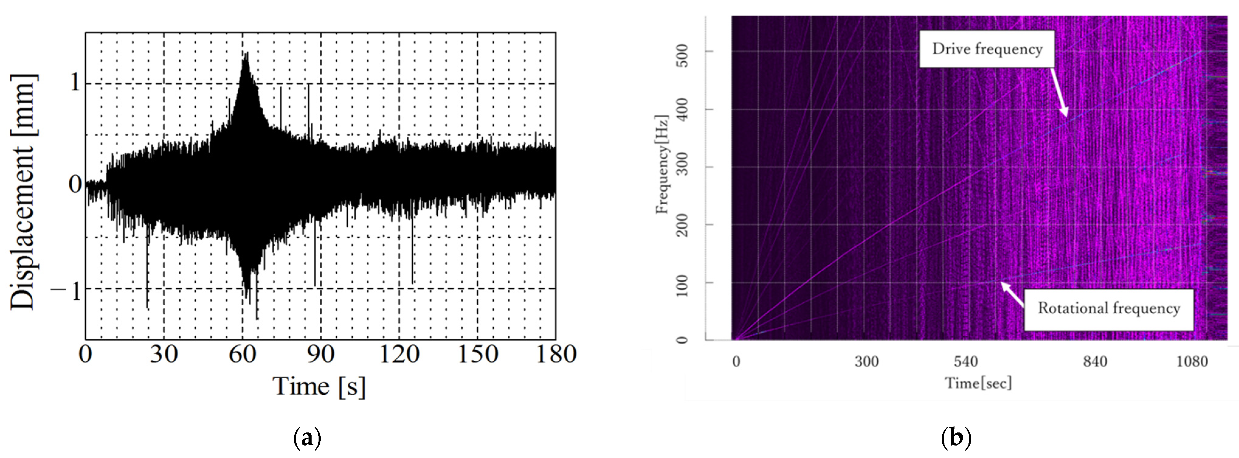
The frequency of the AC voltage waveform generated by the function generator increased continuously from 0 Hz to 500 Hz over approximately 1080 s. At this time, the flywheel was rotating with 1/3 of the applicable frequency.
Figure 13 shows the measurement results of the swing vibration when the flywheel is driven. From the time history response result (Figure 13a), the maximum amplitude of this system is about 1.2 mm. As the air gap at the time of levitation of this system was 2 mm in the radial direction, it could be confirmed that the critical speed can be overcome without control.
Moreover, from the result of flywheel swing experiment (Figure 13), the resonance is found to be around 12 Hz, which is in the low rotation range. Based on this, it was confirmed that the SMB in this research is useful for flywheels that operate in the high-speed rotation range.
In the present study, the drive was only carried out up to 10,000 rpm for safety reasons, owing to the structural strength of the flywheel. The energy stored in the flywheel at 10,000 rpm is approximately 12 kJ.
5. Conclusions
In this study, we aimed to stabilize the radial unstable force generated by a repulsion magnet in the SMB, which is responsible for the axial levitation force required for the floating of the flywheel. This paper can be summarized as follows:
- We devised and manufactured an SMB with a magnetic field that utilized the top and sides of a ring-shaped HTS.
- It was confirmed that the unstable force owing to repulsive magnetic levitation can be stabilized by the developed SMB.
- Compared with previous research, the restoring force characteristics per unit volume of HTS were significantly increased by 4.2 to 4.9 times.
- It was confirmed that the flywheel using the proposed SMB could rotate beyond the swinging resonance speed without a requirement for control and could be stably driven up to the high-speed rotation range.
Based on the above, we succeeded in stabilizing a magnetic repulsion levitation system using an SMB while reducing the amount of HTS used, which was the research goal.
Author Contributions
Conceptualization, I.M.; methodology, I.M. and Y.Z.; validation, I.M., T.T. and Y.Z.; formal analysis, I.M., T.T. and Y.Z.; writing—review and editing, I.M.; visualization, T.T.; project administration, I.M. All authors have read and agreed to the published version of the manuscript.
Funding
This research was funded by JSPS KAKENHI Grant Number JP 17K06224, 22K03992.
Institutional Review Board Statement
Not applicable.
Informed Consent Statement
Not applicable.
Conflicts of Interest
The authors declare no conflict of interest.
References
- Arai, U. Chodendo jiki jikuuke ni yoru furaihoiru chikuden sochi no Kaihatsu (Development of flywheel power storage device using superconducting magnetic bearings). Appl. Phys. 2015, 84, 150–153. [Google Scholar]
- Yamashita, T.; Ogata, M.; Magashima, K. The Superconducting Flywheel Storage Systems using the Superconducting Magnetic Bearing. J. JSAEM 2016, 24, 293–298. [Google Scholar]
- Miyazaki, Y.; Mizuno, K.; Yamashita, T.; Ogata, M.; Hasegawa, H.; Nagashima, K.; Mukoyama, S.; Matsuoka, T.; Nakao, K.; Horiuch, S.; et al. Development of superconducting magnetic bearing for flywheel energy storage system. Cryogenics 2016, 80, 234–237. [Google Scholar] [CrossRef]
- Nagashima, K. Development Overview of a Superconducting Flywheel Energy Storage System for Demonstration Tests. Low Temp. Eng. 2019, 54, 351–358. [Google Scholar] [CrossRef] [Green Version]
- Miyazaki, Y.; Mizuno, K.; Ogata, M.; Yamashita, Y.; Nagashima, K. Development of a Superconducting Magnetic Bearing Capable of Supporting Large Loads in a Flywheel Energy Storage for Railway Application. Q. Rep. RTRI 2020, 61, 54–59. [Google Scholar] [CrossRef] [Green Version]
- Ai, L.; Zhang, G.; Li, W.; Liu, G.; Liu, Q. Optimization of radial-type superconducting magnetic bearing using the Taguchi method. Phys. C Supercond. 2018, 550, 57–64. [Google Scholar] [CrossRef]
- Zou, Y.; Shang, J.; Guan, X.; Bian, X.; Wu, J.; Li, Q. Design and experimental research of superconducting magnetic bearing for helium cold compressor. Cryogenics 2020, 106, 103047. [Google Scholar] [CrossRef]
- Murakami, I.; Shimada, T.; Kobayashi, Y.; Mori, H.; Ando, Y. Stabilization of repulsive-type magnetic levitation system using superconducting magnetic bearing. Int. J. Appl. Electromagn. Mech. 2016, 52, 1607–1613. [Google Scholar] [CrossRef]
Figure 1.
Rotor magnet configuration with magnetic flux convergence.

Figure 2.
HTS magnet configuration with repulsive permanent magnet.
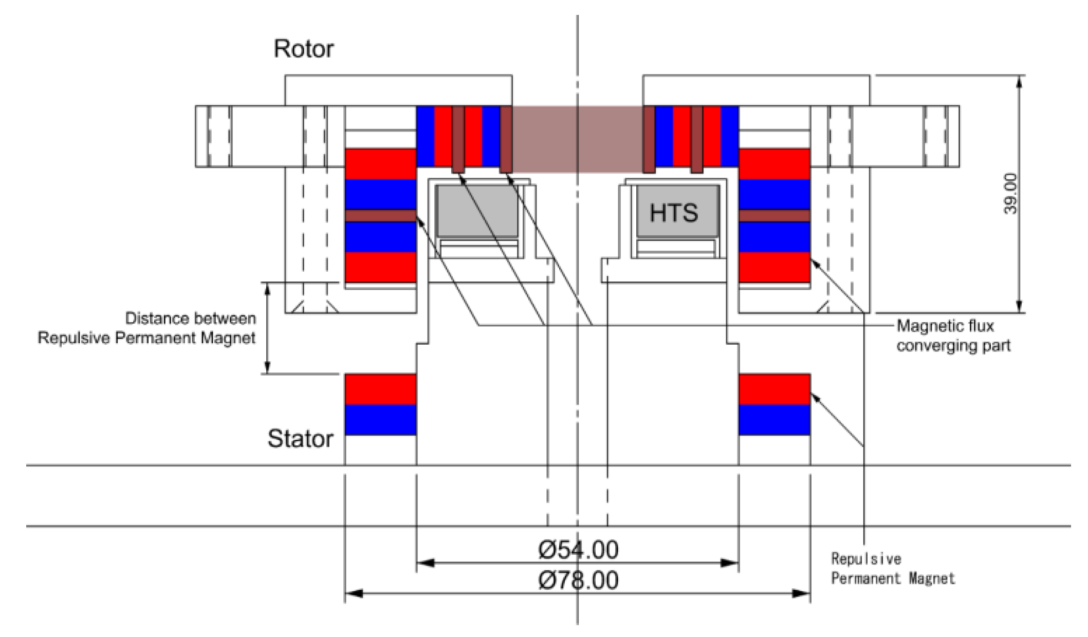
Figure 3.
Photograph of HTS.
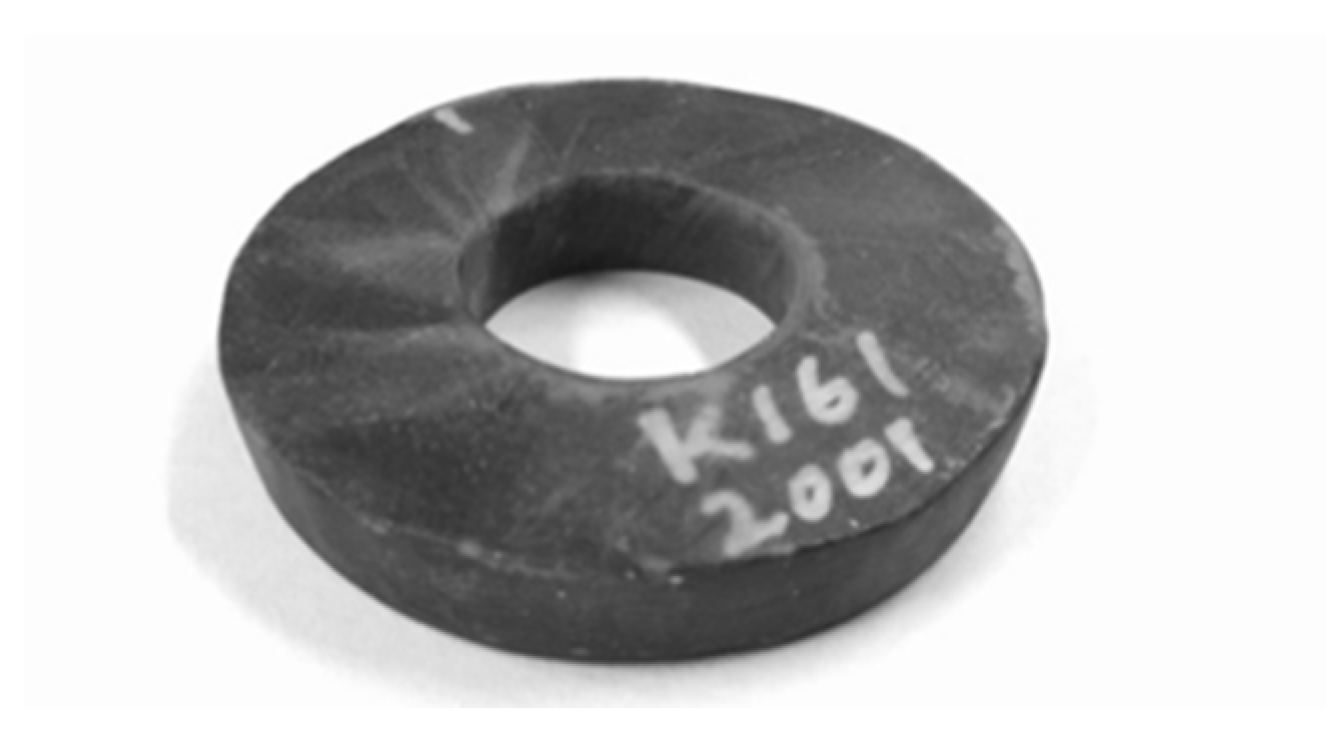
Figure 4.
One-quarter of the model used for simulation.
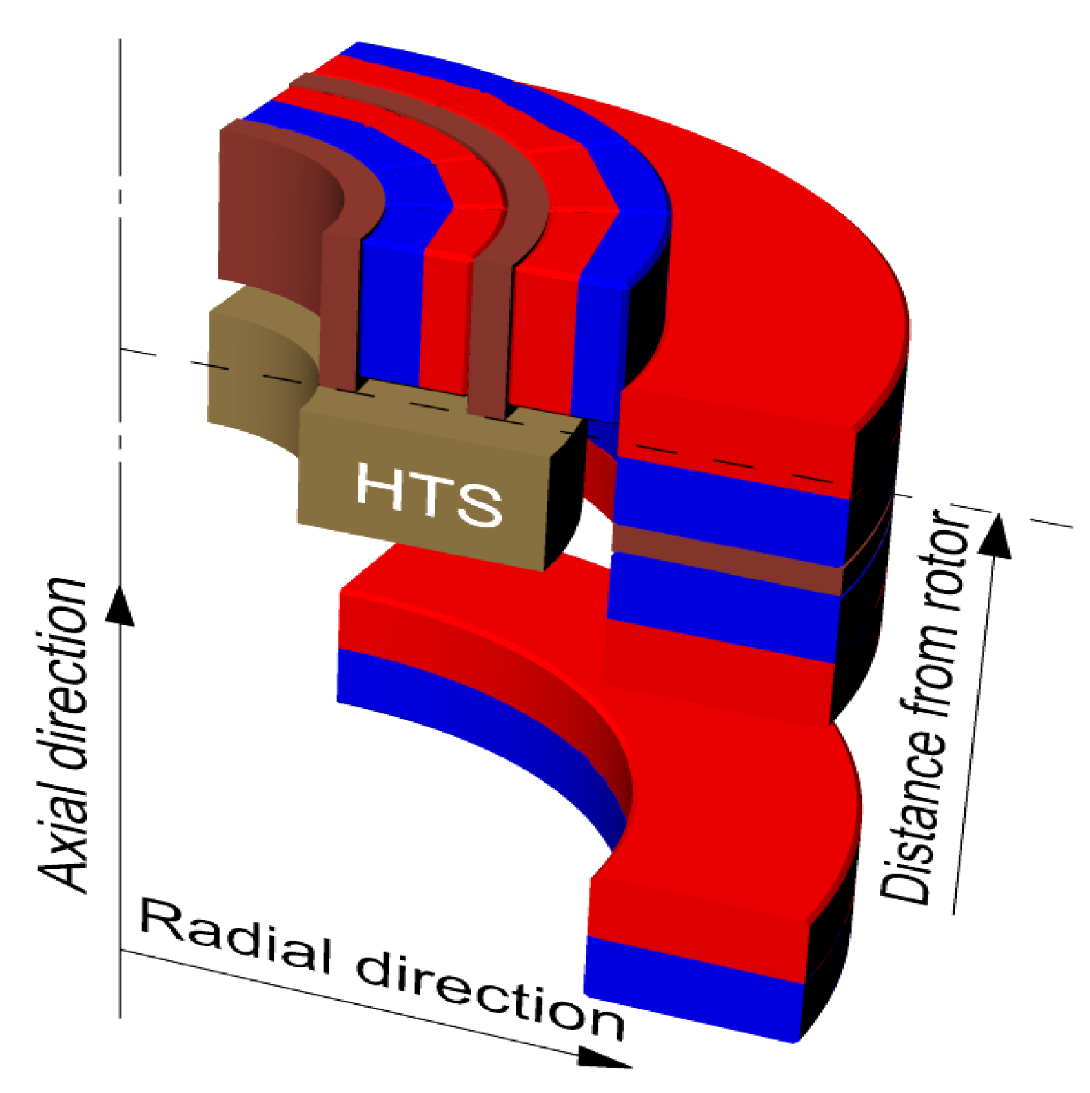
Figure 5.
Magnetic flux density data extraction position shown by numerical analysis: (a) Plot section line at top of HTS, (b) Plot section line at side of HTS.
Figure 5.
Magnetic flux density data extraction position shown by numerical analysis: (a) Plot section line at top of HTS, (b) Plot section line at side of HTS.

Figure 6.
Comparison of magnetic flux density at the top of the HTS. (a) Radial simulation and measurement results, and (b) axial simulation and measurement results.
Figure 6.
Comparison of magnetic flux density at the top of the HTS. (a) Radial simulation and measurement results, and (b) axial simulation and measurement results.

Figure 7.
Comparison of magnetic flux density at the side of the HTS: (a) Radial simulation and measurement results, (b) Axial simulation and measurement results.
Figure 7.
Comparison of magnetic flux density at the side of the HTS: (a) Radial simulation and measurement results, (b) Axial simulation and measurement results.
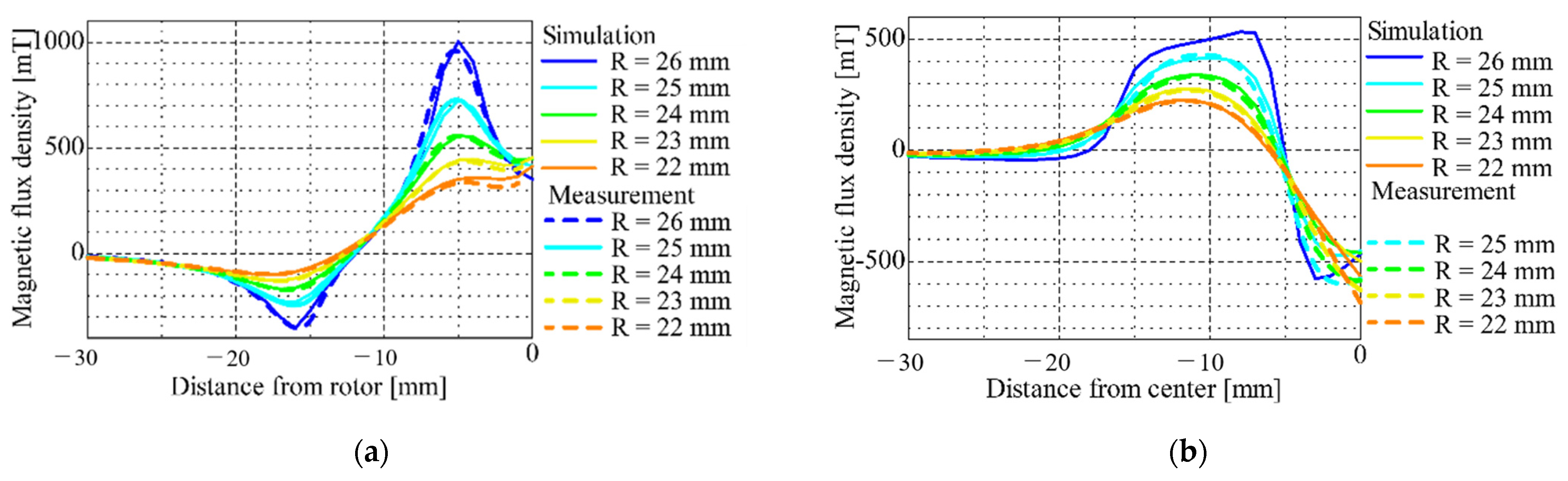
Figure 8.
Measurement results of circumferential variations in magnetic flux density: (a) Radial component, (b) Axial component.
Figure 8.
Measurement results of circumferential variations in magnetic flux density: (a) Radial component, (b) Axial component.
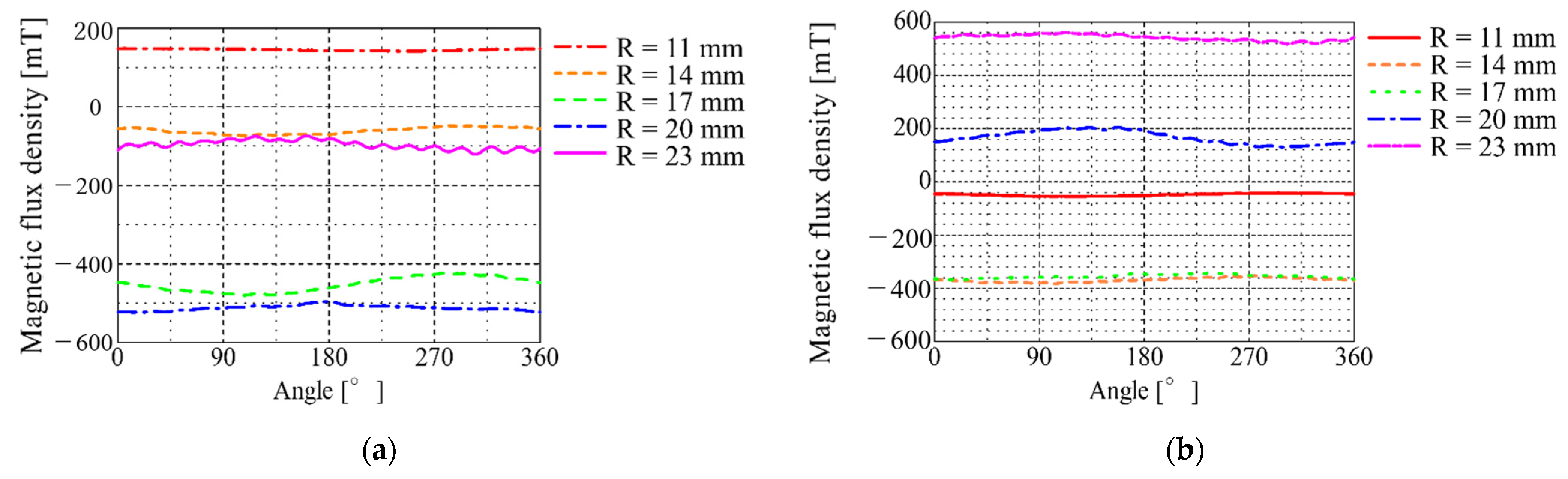
Figure 9.
Measurement results of restoring force in each direction: (a) Radial measurement results, (b) Axial results.
Figure 9.
Measurement results of restoring force in each direction: (a) Radial measurement results, (b) Axial results.

Figure 10.
SMB model of previous research.
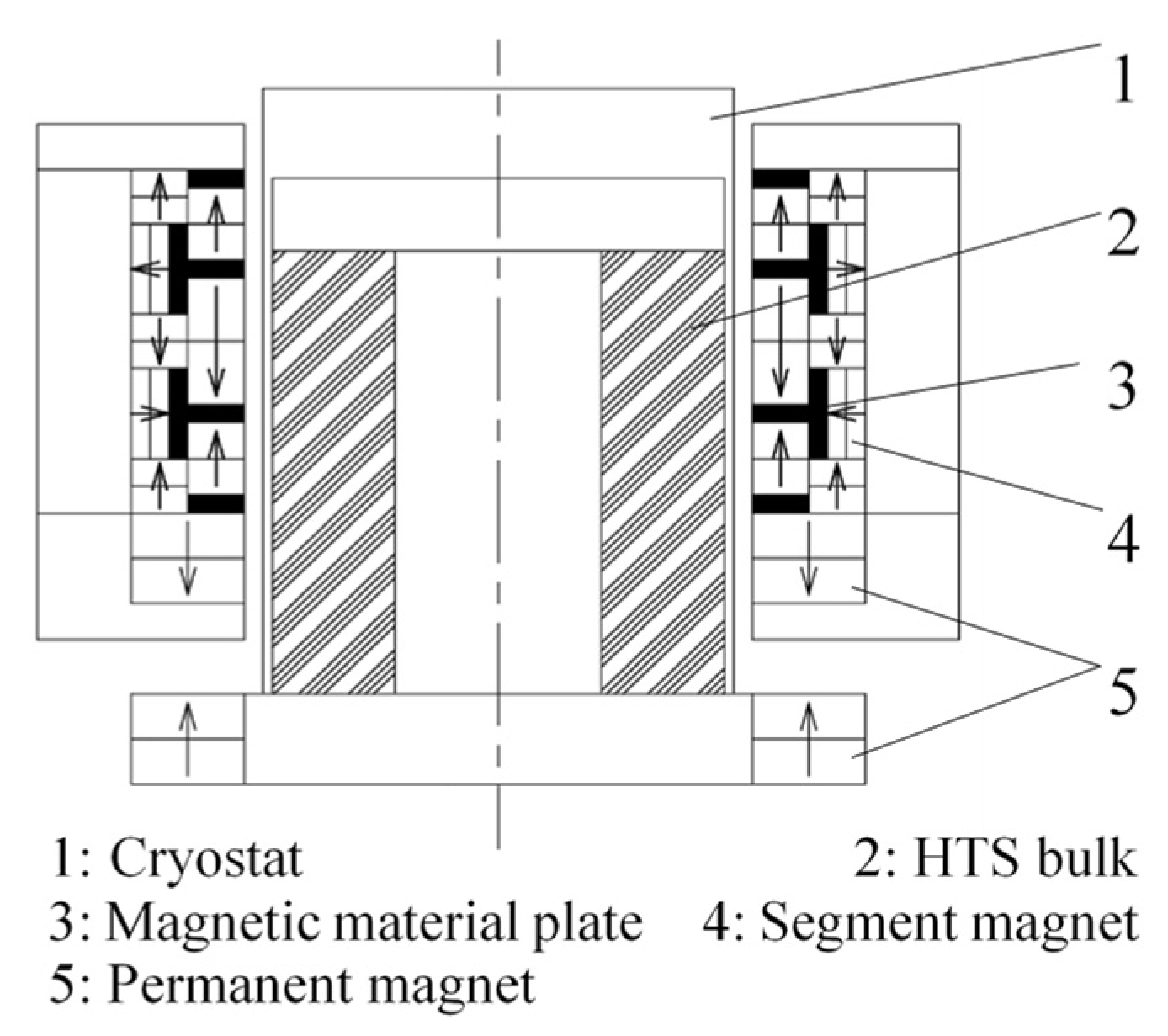
Figure 11.
(a) Geometry and (b) Photogragh of experimental equipment.
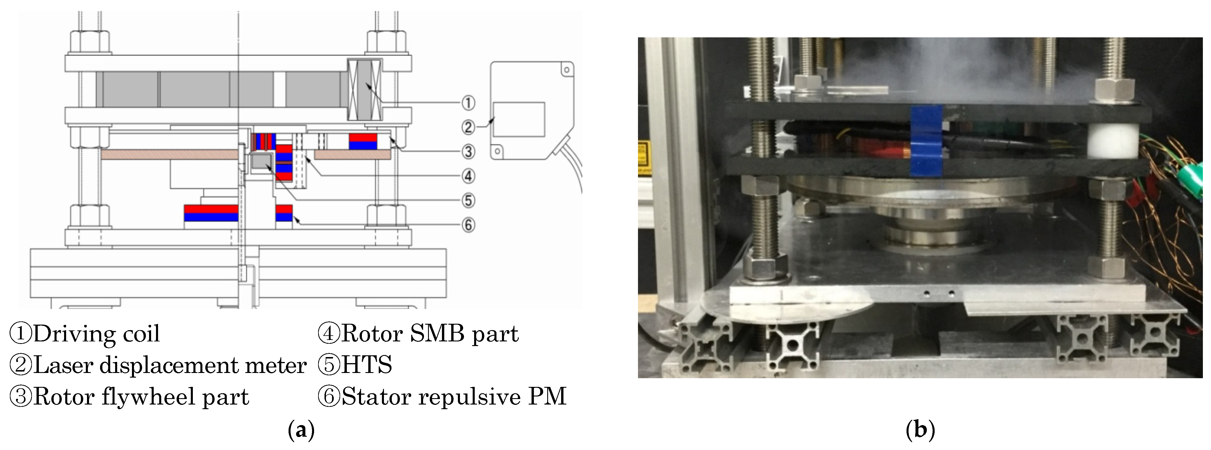
Figure 12.
Scheme of experimental equipment.
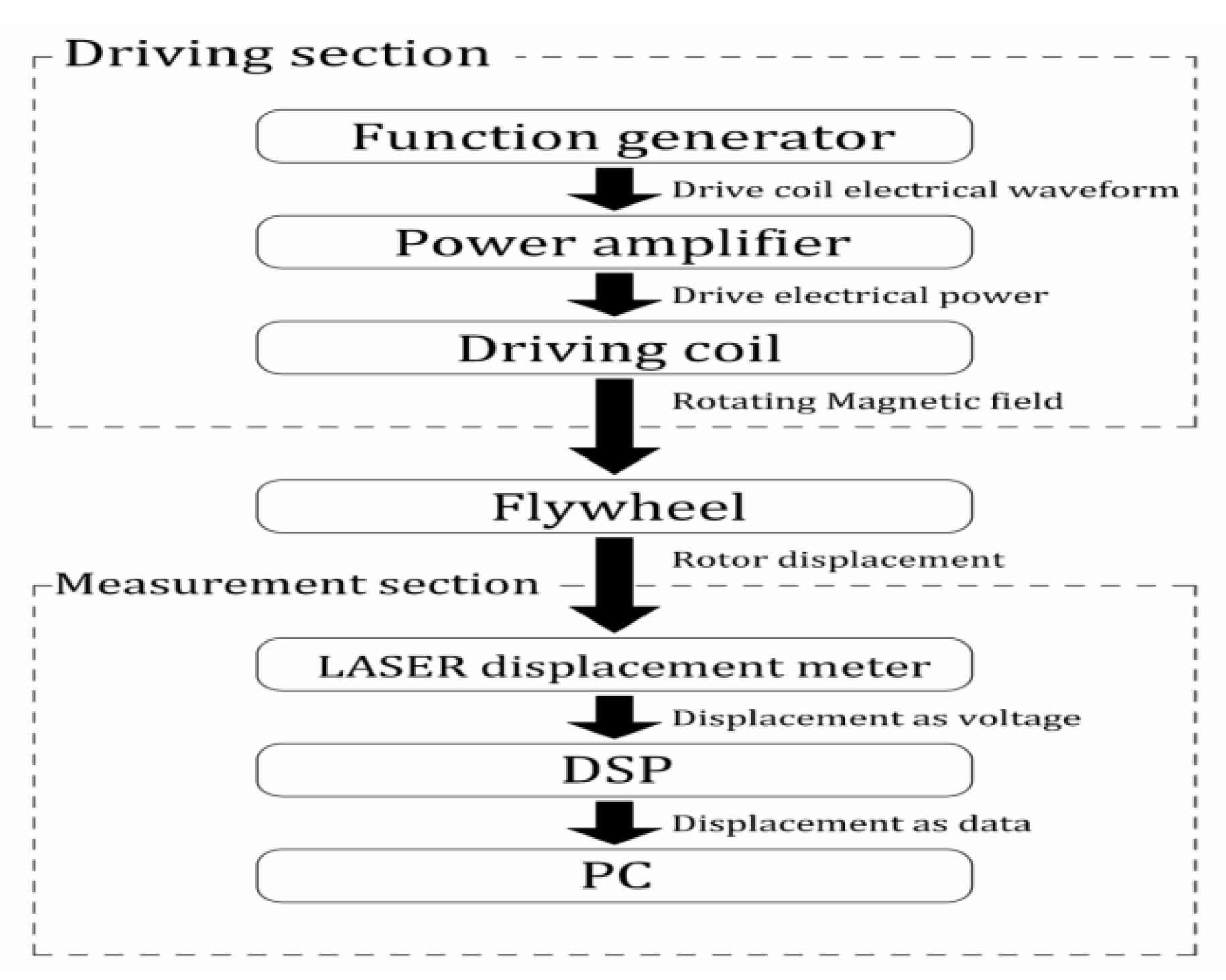
Figure 13.
Results of (a) time and (b) frequency response for flywheel swing displacement.

Table 1.
Specifications of the HTS.
| Items | Detailed Specifications |
|---|---|
| Material composition | Gd-Ba-Cu-O type |
| Maker | Nippon Steel |
| Outside diameter | 47 mm |
| Inside diameter | 20 mm |
| Height | 8 mm |
Table 2.
Simulation conditions.
| Items | Detailed Specifications |
|---|---|
| Analysis type | Three-dimensional static magnetic field analysis |
| Number of elements | 541,884 |
| Number of nodes | 100,480 |
| Boundary conditions | vector potential |
| PM material | NEOMAX 41H, NEOMAX 35H |
| Ferromagnetic material | 50JN1300 |
Table 3.
Comparison with the results of previous research.
| Items | Previous Model with Repulsive PM Gap 10 mm | Present Model with Repulsive PM Gap 10 mm |
|---|---|---|
| Radial restoring force [N/m] | ||
| Axial restoring force [N/m] | ||
| 13.55 × 10⁻⁵ |
Publisher’s Note: MDPI stays neutral with regard to jurisdictional claims in published maps and institutional affiliations. |
© 2022 by the authors. Licensee MDPI, Basel, Switzerland. This article is an open access article distributed under the terms and conditions of the Creative Commons Attribution (CC BY) license (https://creativecommons.org/licenses/by/4.0/).
Share and Cite
MDPI and ACS Style
Murakami, I.; Zhao, Y.; Tashiro, T. Stabilization of a Magnetic Repulsive Levitation Flywheel System Using a High-Efficiency Superconducting Magnetic Bearing. Actuators 2022, 11, 180. https://doi.org/10.3390/act11070180
AMA Style
Murakami I, Zhao Y, Tashiro T. Stabilization of a Magnetic Repulsive Levitation Flywheel System Using a High-Efficiency Superconducting Magnetic Bearing. Actuators. 2022; 11(7):180. https://doi.org/10.3390/act11070180
Chicago/Turabian StyleMurakami, Iwanori, Yiming Zhao, and Tatuhiro Tashiro. 2022. "Stabilization of a Magnetic Repulsive Levitation Flywheel System Using a High-Efficiency Superconducting Magnetic Bearing" Actuators 11, no. 7: 180. https://doi.org/10.3390/act11070180
Note that from the first issue of 2016, this journal uses article numbers instead of page numbers. See further details here.