
Design of Soft Pneumatic Actuator with Two Oblique Chambers for Coupled Bending and Twisting Movements
by
 , , , and
Ebrahim Shahabi
1,2,*,
Behnam Kamare
2,3,
Francesco Visentin
4,
Alessio Mondini
1 and
Barbara Mazzolai
1,* 1
Istituto Italiano di Tecnologia, Bioinspired Soft Robotics Lab, 16163 Genova, GE, Italy
2
Scuola Superiore Sant’Anna, Biorobotics Institute, 56025 Pontedera, PI, Italy
3
Istituto Italiano di Tecnologia, Soft BioRobotics Perception Lab, 16163 Genova, GE, Italy
4
Section Engineeting and Physics, Department of Engineering for Innovation Medicine, Università degli Studi Verona, 37134 Verona, VR, Italy
*
Authors to whom correspondence should be addressed.
Actuators 2023, 12(12), 446; https://doi.org/10.3390/act12120446
Submission received: 19 October 2023
/
Revised: 26 November 2023
/
Accepted: 27 November 2023
/
Published: 1 December 2023
(This article belongs to the Special Issue Soft Actuators for Medical Robotics)
Abstract
:Soft pneumatic network (Pneu-net) actuators are frequently used to achieve sophisticated movements, but they face challenges in producing both bending and twisting motions concurrently. In this paper, we present a new Pneu-net twisting and bending actuator (PTBA) design that enables them to perform complex motions. We achieved this by adjusting the chamber angle, ranging from 15 to 75 degrees, to optimize the bending and twisting movements through finite element analysis and experimental verification. We also investigated the variation trends in bending and twisting motions and determined the actuator’s workspace and maximum grasping force for a variety of objects with different shapes, materials, and sizes. Our findings suggest that PTBA is a promising candidate for advanced applications requiring intricate and bioinspired movements. This new design method offers a path toward achieving these goals.
1. Introduction
Animals are capable of moving their bodies through the activation of specific muscles in response to various stimuli. This remarkable ability is essential for performing a wide range of behaviors, from simple movements such as turning or bending to complex actions like running or flying. In rigid-bodied animals with skeletal structures, the muscles can contract against the bones, acting as levers to amplify and direct forces. In soft-bodied animals that lack rigid skeletal structures, muscles can only contract against fluids or tissues that cannot be compressed, leading to either stiffness or the deformation of the body. The morphological arrangement of the muscles grants animals the capability to implement bending and twisting movements needed to implement complex tasks.
The field of soft robotics focuses on the design and development of soft, flexible robots with the aim of emulating these movements. Research on soft robots relies heavily on bioinspiration, or the imitation of nature, as researchers aim to create more efficient, adaptive, and robust robots by studying natural systems. The last decade has seen the extensive development of soft robots capable of grasping [1], manipulating [2], growing [3], creeping [4], crawling [5], swimming [6], and jumping [7]. Compliant materials are commonly used to construct actuators for soft robots, including silicone rubbers [8], shape memory polymers [9], shape memory alloys [10], electroactive polymers [11], and hydrogels [12]. The actuators can be operated through a variety of stimuli, including pressurized fluids [2], temperature changes [9,10], electric fields [13,14], and chemical reactions [7]. Soft pneumatic actuators (SPAs) are among the most used for various applications due to their numerous advantages, including their ability to perform a wide range of motions through simple inputs, as well as their lightweight properties, low material costs, and high fabrication efficiency [15].
An important feature of SPAs is their integrated bending and twisting motions in three dimensions, which allows for greater dexterity when controlling the actuation mode [16,17]. Two are the main approaches to developing SPAs are the use of fibers to the actuator wall [18,19,20,21,22] and the design of a pneumatic network (Pneu-net) [23,24,25,26]. An actuator with a fiber reinforcement is typically made up of an elastomer body with a monolithic chamber and fibers arranged helically, and an alternate flexible layer [18]. This is possible in fiber-reinforced actuators using a set of fibers arranged at different angles. Each configuration can perform either twisting or bending, and these can also be combined to obtain the sum of the different motions. A detailed analysis was conducted by Connolly et al. [19] to investigate the effect of fiber angle on actuator motion, and an analytical model was developed to facilitate the design process. A mathematical model for the motions exhibited by deformable cylindrical actuators was proposed in the early works of Hirai et al. [16]. By combining parallel fibers and using an additional fiber, Moser et al. [20] developed a snake-like, fiber-reinforced actuator. Using McKibben’s artificial muscles, Peng et al. [27] developed a wearable support device called Funabot-Suit that is based on human muscle architecture. A soft pipe robot with three longitudinally arranged elastic ribbons and a McKibben pneumatic actuator was created by Lin et al. [28] to mimic the serpentine behavior of a snake. The robot can move forward by relying on the intermittent bending of the elastic ribbons, which are activated by a single actuator.
A Pneu-net actuator, instead, relies on a series of connected chambers that work as a network [29]. Pneu-net actuators achieve extension motions due to internal pressure, which inflates their chambers. Due to the presence of a non-extensible layer, a Pneu-net actuator can achieve large amplitude bending motions. In fact, Pneu-net actuators can produce great deformations from a single source of pressure; however, their geometric parameters have a significant impact on their ability to bend. Due to this, a growing interest has been shown in the behavior of the Pneu-net actuator with respect to its design parameters [30,31,32]. Sun et al. [33] proposed an alternative method for achieving helical movement within soft pneumatic actuators by circumferentially shifting the strain-constraining layer. To achieve coupled motions of bending and twisting, an actuator using a Pneu-net should use oblique chambers. The first design created by Ilievski et al. [34] was an embedded network of channels that, when actuated, curled in the form of a helix. According to Gorissen et al. [35], the twisting actuator could be created by combining two opposite bending motions, each of which was realized through a series of angular voids. Chengru Jiang et al. assembled several Pneu-net actuators so that the shape of the actuators would be deformed in a manner similar to the arms of an octopus [36].
Currently, studies focus on changing the design parameters of the entire actuator or a single section of the actuator. In fact, different designs and geometries of Pneu-net actuators may result in different deformations. It is possible for Pneu-net to bend if there is a straight-line distance between the chambers [23,37]; however, if the distances are angled, new deformations, such as spiral motion, may occur [36,38,39,40,41].
In this paper, we present the design, simulation, and characterization of a Pneu-net actuator that can generate coupled bending and bidirectional twisting motions, thanks to the use of a double array of oblique pneumatic chambers. Finite element analysis (FEA) was used to simulate the motions of the actuator and to determine its workspace on the variation in the design parameters. Based on the simulation analysis, an actuator with compartments, suitable for grasping purposes, was fabricated using a simple molding process. A full characterization of the developed prototype was carried out and the results were compared with the output of the simulations. Grasping capabilities were evaluated on a wide range of objects of different sizes and weight, and they were shown to be able to retrieve the objects not only by holding them while bending around, but also using a twisting movement, providing a larger contact area, and adapting to the geometric features of target objects more effectively. Using simulations and experiments, we demonstrate that our new actuator design may guide the design of Pneu-net actuators for a wider range of applications.
2. Materials and Methods
Design and Simulation
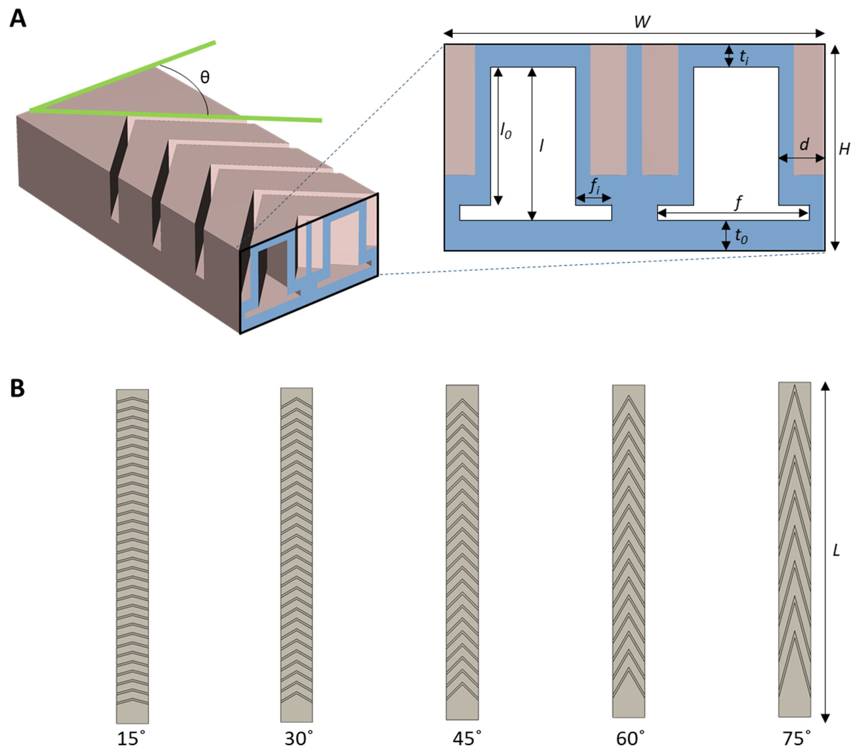
The Pneu-net chamber is usually rectangular in shape and the actuator produces planar movement [42]. Oblique chambers are used to introduce twisting capabilities to the actuators [39]. In this study, we coupled two arrays of oblique chambers into a single actuator (Figure 1A) to achieve bidirectional twisting and bending. The design parameters, and in particular the chamber angle θ, were investigated to analyze the behavior of the actuator (Figure 1B). Changing θ (in our investigation, from 15° to 75° with a 15° step) results in different working spaces of the actuator as a result of the applied pressure to the two pneumatic chambers. Design parameters and in particular the chamber angle θ are reported in Table 1.
For this investigation, we used a finite element model with the Solid Mechanics module of COMSOL Multiphysics 6.0. Since the material that was used to create the actuator is silicon-based (Dragon Skin 20), we used the hyper-elastic coefficients of the incompressible Yeoh strain energy functions [43]. A free tetrahedral mesh, employing normal element size and physics-controlled sequence type, was used to mesh the geometry of the actuator. For the chamber angles of 75, 60, 45, 30, and 15, the total number of domain elements were 20,441,19,749,19,207,18,356, and 16,277, respectively. Gravity and, consequently, the weight of the actuator were considered in the simulations (Dragon Skin 20 density is 1080 kg/m3).
The base of the actuator, where air input tubes are located, is fixed in the XY plane with +Z aligned with the gravity direction (Figure 2). By selecting boundary conditions in this manner, gravity has no effect on the initial state of the actuator. For each inner channel of the actuator, two sets of boundary selections are defined for applying the boundary load as static pressure perpendicular to the desired inner surfaces.
3. Results
3.1. Simulations
As a result of the large deformation of the actuator under higher pressures, some of the outer surfaces between the chambers come into contact with each other. To address this behavior, two sets of outer surfaces were defined as source and destination boundaries, and a direct contact method was considered between these boundaries. Applying the same pressure in both channels results in the actuator bending, while applying pressure in only one channel leads to a twist. Figure 3 shows the resulting actuator behavior resulting from setting the air pressure to 10, 30, 50, and 80 kPa. As shown in the figure, the actuator bends under the influence of balanced air pressures in the channels. Instead, the twisting is caused by applying the same pressure values in one channel and keeping the other not actuated.
3.2. Parameter Optimization
Starting with the simulation data, we analyzed the results to select an optimized version to develop. The ideal design should have both good performance in bending and twisting motion, allowing the use of the actuator in different situations.
Starting with the bending, we extracted the central line of the actuator and plotted the deformation as a function of the applied pressure. Figure 4 shows the results of the analysis. As the results suggest, chamber angles greater than 45° do not show any deformation, even with the maximum pressure (80 kPa) applied. The three remaining configurations, instead, achieved clear two-dimensional bending, resulting in large deformations (Figure 4A). Specifically, the 15° and 30° angled actuators bent up to 265°; instead, the 45° angled one could bend up to 176° (Figure 4B and Figure 3, top).
A similar result (Figure 5) was obtained with the twisting experiments. However, in this case, the 60° and 75° angled actuators produced a visible deformation when pressurized. Despite this, the results are not comparable with the other configurations since the total twisting angle was lower than 12° for both the cases (Figure 5B). As in the bending case, the 15° and 30° angled actuators overperformed in terms of deformations (Figure 5A). The 15° angled one, especially, degenerated in a three-dimensional bending-like configuration, achieving in a total bending of 315°. On the contrary, the 45° angled one resulted in a torsional motion which did not close (angle lower than 180°) but extended along the length of the actuator.
This effect is even more visible considering the maximum contraction of the actuator with respect to the applied pressure. As shown in Figure 6A, the torsional motion of the 15° and 30° angled actuators resulted in a total contraction of the workspace up to 77%, with a large drop even at a lower pressure (40–50 kPa). The 45° angled one, instead, was only shortened by 26% while performing a total twist of 120°. The 60° and 75° angled actuators underperformed with respect to the other configurations, not providing enough torsion (less than 12°) to be used in grasping applications.
Considering the advantages of the different configurations, we selected the 45° angled version to be the optimal solution for a versatile but effective actuator. This is because it can easily achieve approximately 180° bending without intersecting with its own body. Additionally, the ability to twist while protracting its body along its central line allows for more complex behavior.
3.3. Manufacturing
The fabrication process was based on direct casting using 3D-printed molds. We designed the molds in Solidworks (Solid Works 2017, Dassault Systems SolidWorks Corp, Waltham, MA, USA) and printed them using a Fused Deposition Machine (FDM) 3D printer (Creality CR–10, Shenzhen, China). Two of the molds were assembled to form the upper part of the actuator, while a third one was used to cast the bottom layer. For the material, we selected Dragon Skin 20 (Smooth-On Inc., San Francisco, CA, USA). Its two-component silicone was mixed and defoamed before being poured into the molds. After curing, the two parts of the actuator were removed from the molds and then connected with a thin layer of the same material. Figure 7 depicts the steps needed for the casting of the actuator.
3.4. Workspace Analysis
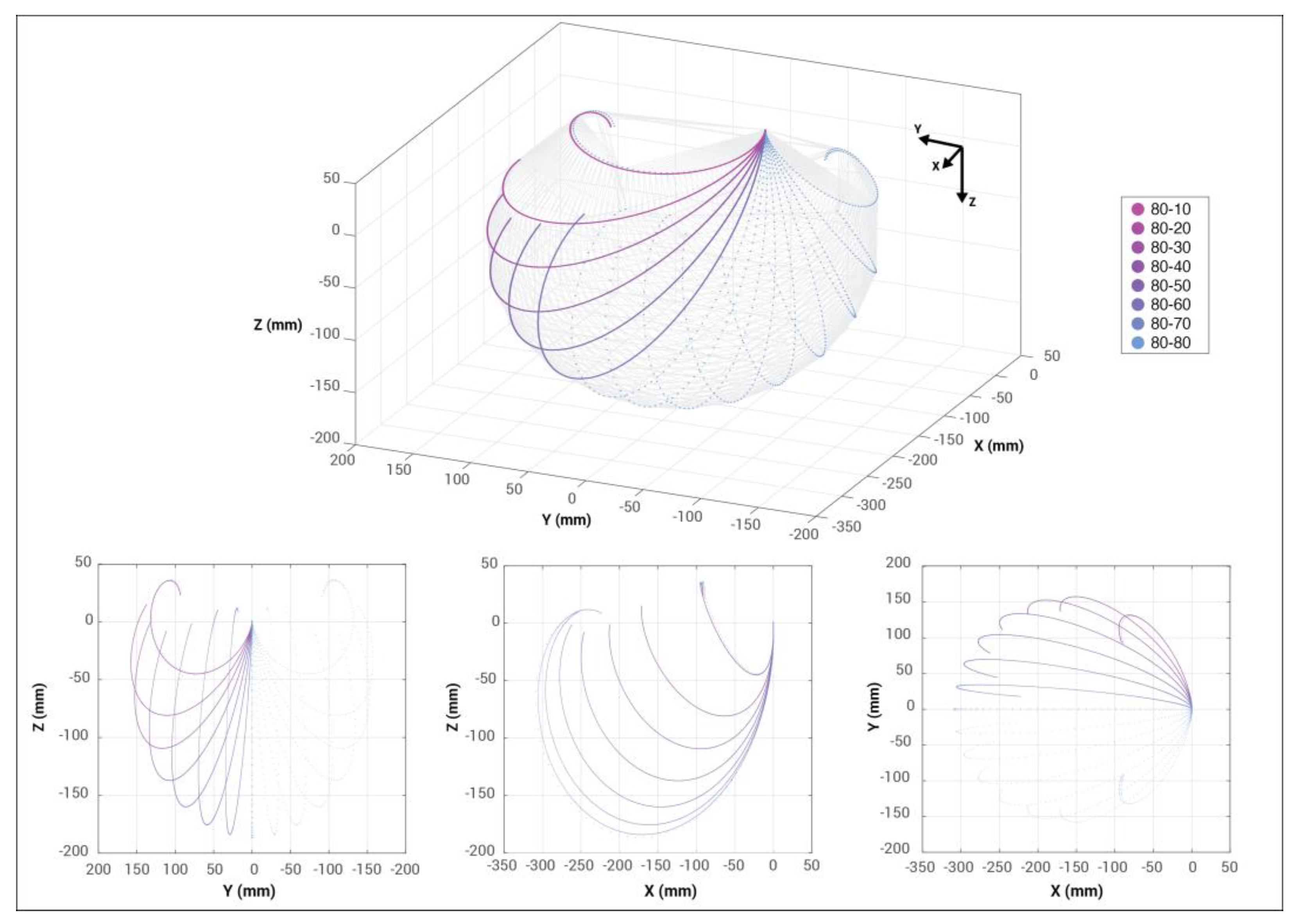
To assess the results of the simulation and to verify the performance of the develop actuator, we evaluated its workspace by pressurizing each chamber independently and then together. For the range of pressure, we selected values between 0 and 80 kPa with a fixed step of 10 kPa. For a low range of pressures (up to 30 kPa), the effects on the actuator are negligible both in the simulation and in the prototype. Appreciable results are in the range of 70–80 kPa. We found that an optimal value for a fast and reliable motion of the actuator is 80 kPa; thus, to extract the workspace, we selected this value as the reference to obtain the maximum displacement of the actuator. Results are presented in Figure 8.
3.5. Grasping Force
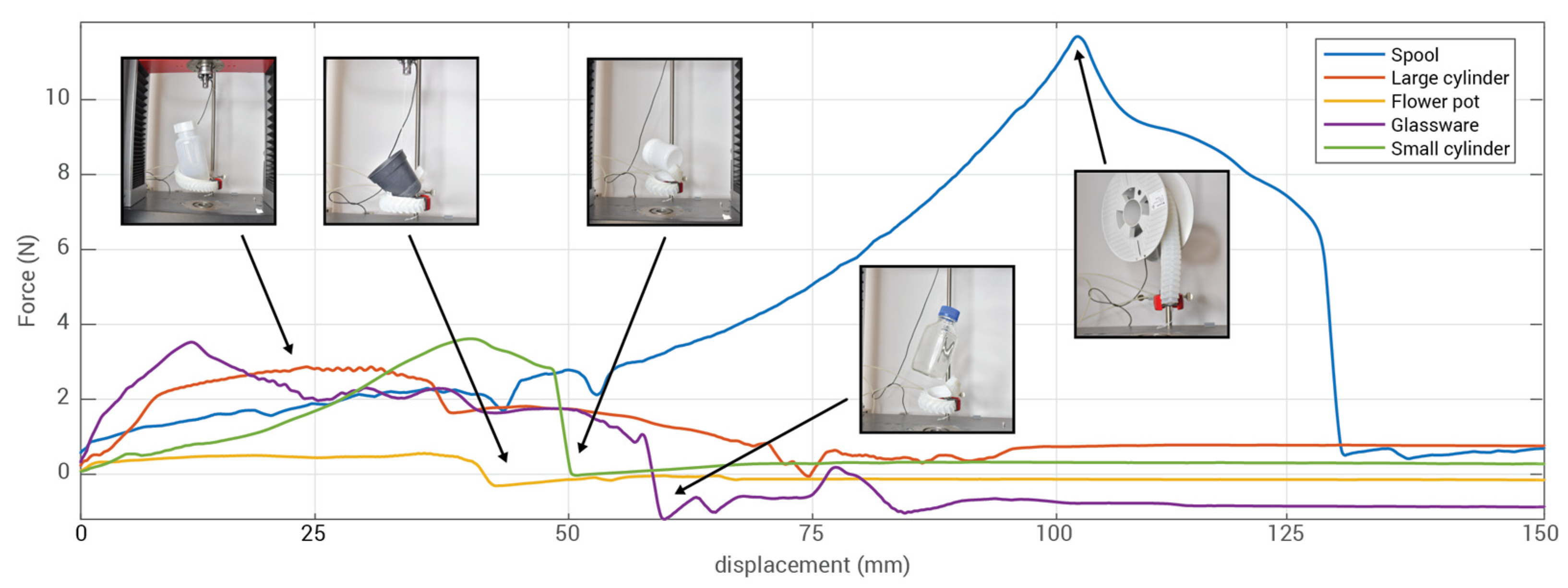
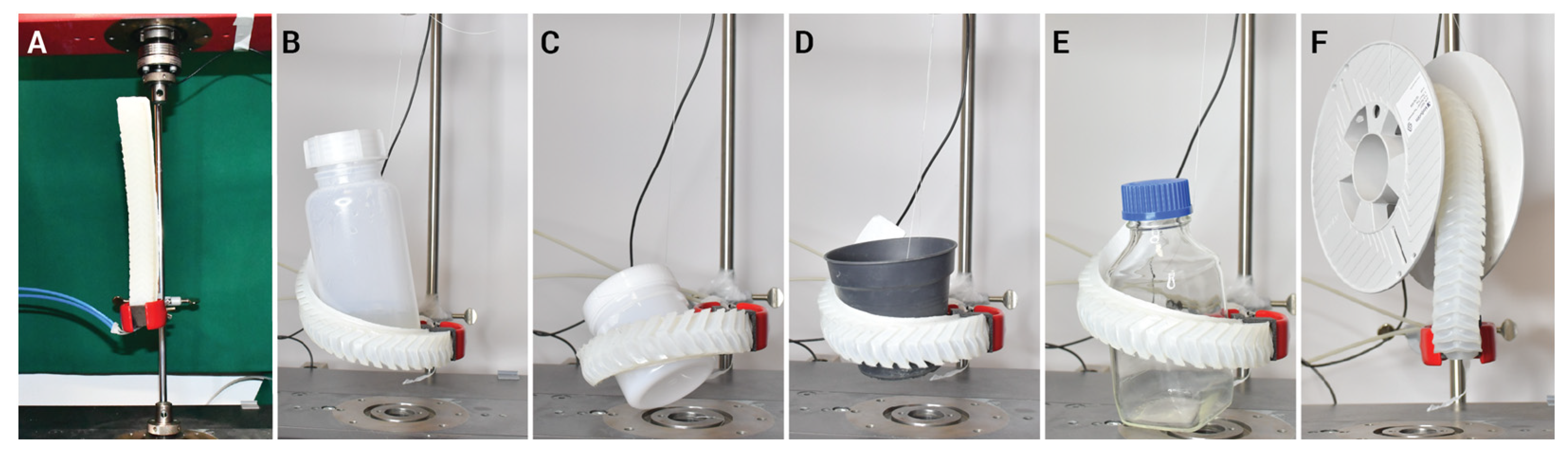
We tested the grasping capability of the developed soft actuator by fixing one end as shown in Figure 9. and leaving the rest of the body free to grasp a target object. As a sample of complex shapes, we selected four objects to be grasped: plastic and glass bottles, a plastic cup, a plastic vase, and a large filament spool. Each object had a different weight and size and would require a specific tool to properly grasp it. However, with the proposed actuator, we could manage the grasping of all the objects by pressurizing both the chambers with 80 kPa, obtaining a helical structure that was attached to the object. Depending the shape of the object, the strategy of grasping is different. For example, a large filament spool must be grasped by activating both channels (bending) to create maximum contact, while it is better to twist around the object to pick up the bottle or flowerpot.
During the experiment, we connected each object to a linear stage machine (Z005, Zwick/Roell, Ulm, Germany) which has a loadcell (Xforce-P, 1 kN, Zwick/Roell). The linear stage was programmed to move upwards by 150 mm while pulling the object from the grasp of the actuator at a constant speed of 5 mm/s. Depending on the size of the object and its weight, the time and the force needed to remove the object from the grasp change. We measured a peak grasping force of 12 N for the spool, which was grasped by twisting the actuator around the central part. For all the other objects, we achieved a mean grasping force of 2.23 N with peaks of 3.85 N when grasping the objects by bending around them. Figure 10 shows the results of the experiment.
4. Conclusions and Discussion
In this paper, we present an innovative design of a soft pneumatic actuator known as the Soft Pneu-net, which exhibits a unique combination of twisting and bending capabilities. Through a meticulous analysis using the finite element method (FEM), we thoroughly examined the behavior of the actuator across various chamber angles, ultimately identifying the most effective configurations for achieving versatile grasping motions on a diverse array of objects.
Our primary objective was to develop an actuator that excels in both bending and twisting movements, thereby opening up new possibilities for a wide range of applications. To accomplish this, we conducted a detailed investigation into the deformation patterns of the actuator’s central line, carefully studying its response to varying pressure levels. Notably, our findings showcased that chamber angles below 45° exhibited no deformation even at maximum pressure (80 kPa). However, configurations with angles of 45°, 30°, and 15° exhibited significant two-dimensional bending with remarkable deformations. This trend was consistent in the twisting experiments as well, further validating our observations (see Figure 5).
Drawing upon the advantages offered by different configurations, we concluded that the 45° angled version of the actuator represents a highly versatile and efficient solution. Leveraging the simulation data, we determined the actuator’s workspace and successfully manufactured the actuator with the chosen 45° angle. Additionally, we conducted a comprehensive series of tests involving objects with diverse sizes, materials, and shapes to thoroughly evaluate the actuator’s grasping force.
The actuator demonstrated performance with a peak grasping force of 3.5 N and a mean grasping force of 2.23 N through simple coiling, exceeding our initial expectations. Moreover, the twisting actuation demonstrated exceptional strength, yielding a peak force of over 12 N. These findings not only underline the unique capabilities of the Soft Pneu-net actuator but also offer novel insights into its potential for performing complex movements and grasping a wide range of objects. The novelty of this study lies in the development of a novel actuator design that combines both twisting and bending functionalities. These findings hold substantial implications for the design and development of soft robotic systems, marking a significant step toward their widespread application in diverse fields.
Author Contributions
Conceptualization, E.S.; methodology, E.S. and B.K.; software, B.K.; validation, E.S., B.K. and F.V.; formal analysis, E.S., B.K. and F.V.; resources, B.M.; data curation, F.V.; writing—original draft preparation, E.S., B.K., F.V. and A.M.; writing—review and editing, E.S., B.K., F.V., A.M. and B.M.; visualization, F.V.; supervision, B.M.; funding acquisition, B.M. All authors have read and agreed to the published version of the manuscript.
Funding
This work was carried out within the framework of the project “RAISE-Robotics and AI for Socio-economic Empowerment” and was supported by European Union-NextGenerationEU.
Data Availability Statement
The data presented in this study are available on request from the corresponding author.
Conflicts of Interest
The authors declare no conflict of interest.
References
- Deimel, R.; Brock, O. A Novel Type of Compliant and Underactuated Robotic Hand for Dexterous Grasping. Int. J. Robot. Res. 2016, 35, 161–185. [Google Scholar] [CrossRef]
- Shepherd, R.F.; Ilievski, F.; Choi, W.; Morin, S.A.; Stokes, A.A.; Mazzeo, A.D.; Chen, X.; Wang, M.; Whitesides, G.M. Multigait Soft Robot. Proc. Natl. Acad. Sci. USA 2011, 108, 20400–20403. [Google Scholar] [CrossRef] [PubMed]
- Sadeghi, A.; Mondini, A.; Mazzolai, B. Toward Self-Growing Soft Robots Inspired by Plant Roots and Based on Additive Manufacturing Technologies. Soft Robot. 2017, 4, 211–223. [Google Scholar] [CrossRef] [PubMed]
- Lin, H.-T.; Leisk, G.G.; Trimmer, B. GoQBot: A Caterpillar-Inspired Soft-Bodied Rolling Robot. Bioinspiration Biomim. 2011, 6, 026007. [Google Scholar] [CrossRef]
- Calisti, M.; Arienti, A.; Renda, F.; Levy, G.; Hochner, B.; Mazzolai, B.; Dario, P.; Laschi, C. Design and Development of a Soft Robot with Crawling and Grasping Capabilities; IEEE: Saint Paul, MN, USA, 2012; pp. 4950–4955. [Google Scholar]
- Li, G.; Chen, X.; Zhou, F.; Liang, Y.; Xiao, Y.; Cao, X.; Zhang, Z.; Zhang, M.; Wu, B.; Yin, S. Self-Powered Soft Robot in the Mariana Trench. Nature 2021, 591, 66–71. [Google Scholar] [CrossRef] [PubMed]
- Lee, H.; Xia, C.; Fang, N.X. First Jump of Microgel; Actuation Speed Enhancement by Elastic Instability. Soft Matter 2010, 6, 4342–4345. [Google Scholar] [CrossRef]
- Walker, J.; Zidek, T.; Harbel, C.; Yoon, S.; Strickland, F.S.; Kumar, S.; Shin, M. Soft Robotics: A Review of Recent Developments of Pneumatic Soft Actuators; Multidisciplinary Digital Publishing Institute: Basel, Switzerland, 2020; Volume 9, p. 3. [Google Scholar]
- Shen, Q.; Trabia, S.; Stalbaum, T.; Palmre, V.; Kim, K.; Oh, I.-K. A Multiple-Shape Memory Polymer-Metal Composite Actuator Capable of Programmable Control, Creating Complex 3D Motion of Bending, Twisting, and Oscillation. Sci. Rep. 2016, 6, 24462. [Google Scholar] [CrossRef]
- Rodrigue, H.; Wang, W.; Han, M.-W.; Kim, T.J.; Ahn, S.-H. An Overview of Shape Memory Alloy-Coupled Actuators and Robots. Soft Robot. 2017, 4, 3–15. [Google Scholar] [CrossRef]
- Carpi, F.; Kornbluh, R.; Sommer-Larsen, P.; Alici, G. Electroactive Polymer Actuators as Artificial Muscles: Are They Ready for Bioinspired Applications? Bioinspiration Biomim. 2011, 6, 045006. [Google Scholar] [CrossRef]
- Visentin, F.; Murali Babu, S.P.; Meder, F.; Mazzolai, B. Selective Stiffening in Soft Actuators by Triggered Phase Transition of Hydrogel-Filled Elastomers. Adv. Funct. Mater. 2021, 31, 2101121. [Google Scholar] [CrossRef]
- Kofod, G.; Wirges, W.; Paajanen, M.; Bauer, S. Energy Minimization for Self-Organized Structure Formation and Actuation. Appl. Phys. Lett. 2007, 90, 081916. [Google Scholar] [CrossRef]
- Mao, Z.; Peng, Y.; Hu, C.; Ding, R.; Yamada, Y.; Maeda, S. Soft Computing-Based Predictive Modeling of Flexible Electrohydrodynamic Pumps. Biomim. Intell. Robot. 2023, 3, 100114. [Google Scholar] [CrossRef]
- Tauber, F.; Desmulliez, M.; Piccin, O.; Stokes, A.A. Perspective for Soft Robotics: The Field’s Past and Future. Bioinspiration Biomim. 2023, 18, 035001. [Google Scholar] [CrossRef] [PubMed]
- Hirai, S.; Masui, T.; Kawamura, S. Prototyping Pneumatic Group Actuators Composed of Multiple Single-Motion Elastic Tubes. J. Robot. Soc. Jpn. 2002, 20, 299–306. [Google Scholar] [CrossRef]
- Martinez, R.V.; Branch, J.L.; Fish, C.R.; Jin, L.; Shepherd, R.F.; Nunes, R.M.; Suo, Z.; Whitesides, G.M. Robotic Tentacles with Three-dimensional Mobility Based on Flexible Elastomers. Adv. Mater. 2013, 25, 205–212. [Google Scholar] [CrossRef]
- Wang, B.; McDaid, A.; Biglari-Abhari, M.; Giffney, T.; Aw, K. A Bimorph Pneumatic Bending Actuator by Control of Fiber Braiding Angle. Sens. Actuators A Phys. 2017, 257, 173–184. [Google Scholar] [CrossRef]
- Connolly, F.; Walsh, C.J.; Bertoldi, K. Automatic Design of Fiber-Reinforced Soft Actuators for Trajectory Matching. Proc. Natl. Acad. Sci. USA 2017, 114, 51–56. [Google Scholar] [CrossRef]
- Bishop-Moser, J.; Krishnan, G.; Kim, C.; Kota, S. Design of Soft Robotic Actuators Using Fluid-Filled Fiber-Reinforced Elastomeric Enclosures in Parallel Combinations; IEEE: Vilamoura-Algarve, Portugal, 2012; pp. 4264–4269. [Google Scholar]
- Robertson, M.A.; Sadeghi, H.; Florez, J.M.; Paik, J. Soft Pneumatic Actuator Fascicles for High Force and Reliability. Soft Robot. 2017, 4, 23–32. [Google Scholar] [CrossRef]
- Bishop-Moser, J.; Kota, S. Towards Snake-like Soft Robots: Design of Fluidic Fiber-Reinforced Elastomeric Helical Manipulators; IEEE: Tokyo, Japan, 2013; pp. 5021–5026. [Google Scholar]
- de Payrebrune, K.M.; O’Reilly, O.M. On Constitutive Relations for a Rod-Based Model of a Pneu-Net Bending Actuator. Extrem. Mech. Lett. 2016, 8, 38–46. [Google Scholar] [CrossRef]
- Galloway, K.C.; Becker, K.P.; Phillips, B.; Kirby, J.; Licht, S.; Tchernov, D.; Wood, R.J.; Gruber, D.F. Soft Robotic Grippers for Biological Sampling on Deep Reefs. Soft Robot. 2016, 3, 23–33. [Google Scholar] [CrossRef]
- Hao, Y.; Wang, T.; Ren, Z.; Gong, Z.; Wang, H.; Yang, X.; Guan, S.; Wen, L. Modeling and Experiments of a Soft Robotic Gripper in Amphibious Environments. Int. J. Adv. Robot. Syst. 2017, 14, 1729881417707148. [Google Scholar] [CrossRef]
- Shahabi, E.; Lu, W.-H.; Lin, P.T.; Kuo, C.-H. Computer Vision-Based Object Recognition and Automatic Pneumatic Soft Gripping; American Society of Mechanical Engineers: New York, NY, USA, 2019; Volume 59292, p. V009T12A006. [Google Scholar]
- Peng, Y.; Sakai, Y.; Nakagawa, K.; Funabora, Y.; Aoyama, T.; Yokoe, K.; Doki, S. Funabot-Suit: A Bio-Inspired and McKibben Muscle-Actuated Suit for Natural Kinesthetic Perception. Biomim. Intell. Robot. 2023, 3, 100127. [Google Scholar] [CrossRef]
- Lin, Y.; Xu, Y.-X.; Juang, J.-Y. Single-Actuator Soft Robot for in-Pipe Crawling. Soft Robot. 2023, 10, 174–186. [Google Scholar] [CrossRef]
- Polygerinos, P.; Lyne, S.; Wang, Z.; Nicolini, L.F.; Mosadegh, B.; Whitesides, G.M.; Walsh, C.J. Towards a Soft Pneumatic Glove for Hand Rehabilitation; IEEE: Tokyo, Japan, 2013; pp. 1512–1517. [Google Scholar]
- Liu, Z.; Wang, F.; Liu, S.; Tian, Y.; Zhang, D. Modeling and Analysis of Soft Pneumatic Network Bending Actuators. IEEE/ASME Trans. Mechatron. 2020, 26, 2195–2203. [Google Scholar] [CrossRef]
- Zhao, S.; Li, D.; Xiang, J. Design and Application of PneuNets Bending Actuator. Aircr. Eng. Aerosp. Technol. 2020, 92, 1539–1546. [Google Scholar] [CrossRef]
- Lin, P.T.; Shahabi, E.; Yang, K.-A.; Yao, Y.-T.; Kuo, C.-H. Parametrically Modeled DH Table for Soft Robot Kinematics: Case Study for a Soft Gripper; Springer: Berlin/Heidelberg, Germany, 2019; pp. 617–625. [Google Scholar]
- Sun, Y.; Song, Y.S.; Paik, J. Characterization of Silicone Rubber Based Soft Pneumatic Actuators; IEEE: Tokyo, Japan, 2013; pp. 4446–4453. [Google Scholar]
- Ilievski, F.; Mazzeo, A.D.; Shepherd, R.F.; Chen, X.; Whitesides, G.M. Soft Robotics for Chemists. Angew. Chem. 2011, 123, 1930–1935. [Google Scholar] [CrossRef]
- Gorissen, B.; Chishiro, T.; Shimomura, S.; Reynaerts, D.; De Volder, M.; Konishi, S. Flexible Pneumatic Twisting Actuators and Their Application to Tilting Micromirrors. Sens. Actuators A Phys. 2014, 216, 426–431. [Google Scholar] [CrossRef]
- Jiang, C.; Wang, D.; Zhao, B.; Liao, Z.; Gu, G. Modeling and Inverse Design of Bio-Inspired Multi-Segment Pneu-Net Soft Manipulators for 3D Trajectory Motion. Appl. Phys. Rev. 2021, 8, 041416. [Google Scholar] [CrossRef]
- Bira, N.; Dhagat, P.; Davidson, J.R. Tuning the Grasping Strength of Soft Actuators with Magnetic Elastomer Fingertips. Smart Mater. Struct. 2022, 31, 045013. [Google Scholar] [CrossRef]
- Hu, W.; Li, W.; Alici, G. 3D Printed Helical Soft Pneumatic Actuators; IEEE: Auckland, New Zealand, 2018; pp. 950–955. [Google Scholar]
- Wang, T.; Ge, L.; Gu, G. Programmable Design of Soft Pneu-Net Actuators with Oblique Chambers Can Generate Coupled Bending and Twisting Motions. Sens. Actuators A Phys. 2018, 271, 131–138. [Google Scholar] [CrossRef]
- Gu, G.; Wang, D.; Ge, L.; Zhu, X. Analytical Modeling and Design of Generalized Pneu-Net Soft Actuators with Three-Dimensional Deformations. Soft Robot. 2021, 8, 462–477. [Google Scholar] [CrossRef] [PubMed]
- Shahabi, E.; Yao, Y.-T.; Chuang, C.-H.; Lin, P.T.; Kuo, C.-H. Design and Testing of 2-Degree-of-Freedom (DOF) Printable Pneumatic Soft Finger; Springer: Berlin/Heidelberg, Germany, 2019; pp. 298–308. [Google Scholar]
- Mosadegh, B.; Polygerinos, P.; Keplinger, C.; Wennstedt, S.; Shepherd, R.F.; Gupta, U.; Shim, J.; Bertoldi, K.; Walsh, C.J.; Whitesides, G.M. Pneumatic Networks for Soft Robotics That Actuate Rapidly. Adv. Funct. Mater. 2014, 24, 2163–2170. [Google Scholar] [CrossRef]
- Marechal, L.; Balland, P.; Lindenroth, L.; Petrou, F.; Kontovounisios, C.; Bello, F. Toward a Common Framework and Database of Materials for Soft Robotics. Soft Robot. 2021, 8, 284–297. [Google Scholar] [CrossRef] [PubMed]
Figure 1.
Schematic model the Pneu-net combination-twisting-and-bending actuator (PTBA). (A) The parameters of designing the soft pneumatic actuator. (B) Schematic models of the actuators with different oblique angles.
Figure 1.
Schematic model the Pneu-net combination-twisting-and-bending actuator (PTBA). (A) The parameters of designing the soft pneumatic actuator. (B) Schematic models of the actuators with different oblique angles.

Figure 2.
(A) An illustration of the geometry of the actuator, the location of the fixed constraint, and the direction of gravity. (B) Cross–section shows the position of right and left channels in the actuator. (C) The location of the contact points is defined throughout the actuator. (D) The reference point is positioned at the free end of the actuator and the pressure–displacement output is compared to this point.
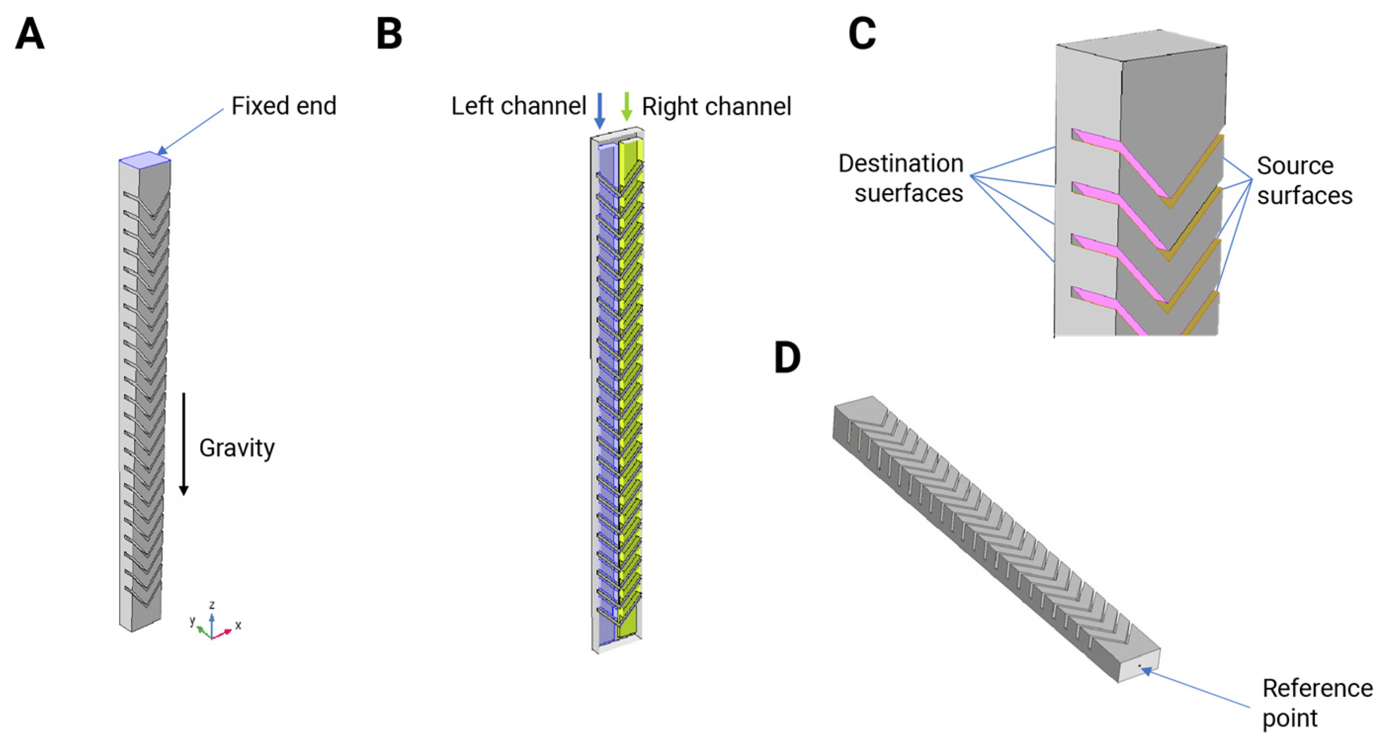
Figure 3.
(Top) Bending due to applying equal air pressure in both channels (80 kPa). (Bottom) Twisting due to an asymmetric air pressure application (one channel at 80 kPa and the other at 0).
Figure 3.
(Top) Bending due to applying equal air pressure in both channels (80 kPa). (Bottom) Twisting due to an asymmetric air pressure application (one channel at 80 kPa and the other at 0).
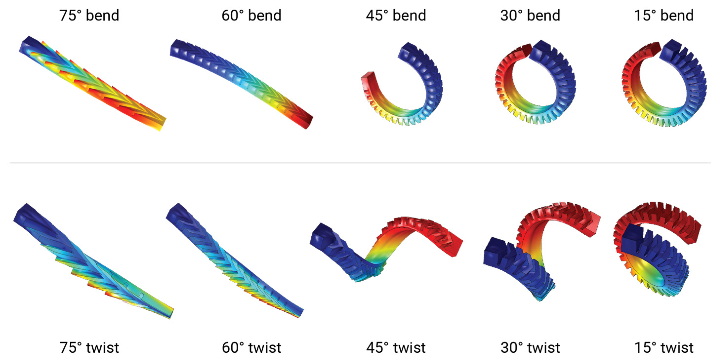
Figure 4.
Performance of the actuators’ bending. (A) Maximum bending as a function of the different test chamber angles. The bold lines show the motion of the reference point (tip of the actuator) when increasing the pressure from 0 to 80 kPa. Dot–dashed lines, instead, show the final deformation of the actuator when pressurized at 80 kPa. (B) Maximum bending angle achieved by the actuators when pressurized at 80 kPa. The 60° and 75° angled actuators do not perform substantial motions to move from their at–rest configuration.

Figure 5.
Performance of the actuators’ twist motion. (A) Maximum deformation as a function of the different test chamber angles. The bold lines show the motion of the reference point (tip of the actuator) while increasing the pressure from 0 to 80 kPa. Dot–dashed lines, instead, show the final deformation of the actuator when pressurized to 80 kPa. (B) Maximum bending angle achieved by the actuators when pressurized at 80 kPa. The 60° and 75° angled actuators do not perform substantial motions to move from their at–rest configuration.
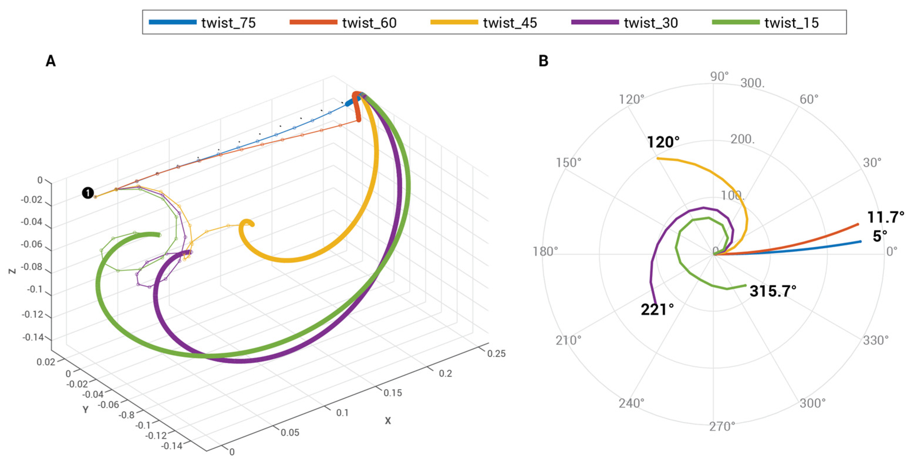
Figure 6.
(A) Contraction of the actuator with respect to the applied pressure. The larger the chamber angle, the higher the achievable contraction rate. This is not always a positive result since the twisting motion can degenerate in a three–dimensional bending around the fixed point. (B) Bending angle (at 80 kPa) plotted against the actuator length.
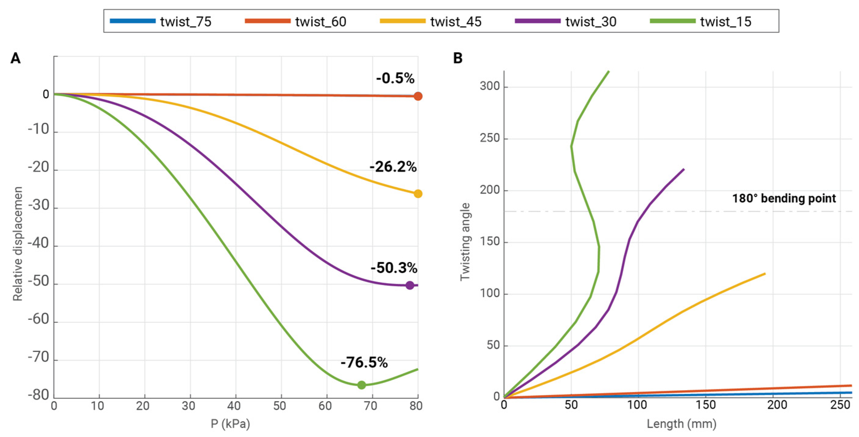
Figure 7.
Schematic of the manufacturing process of two-degrees-of-freedom Pneu-net actuator.
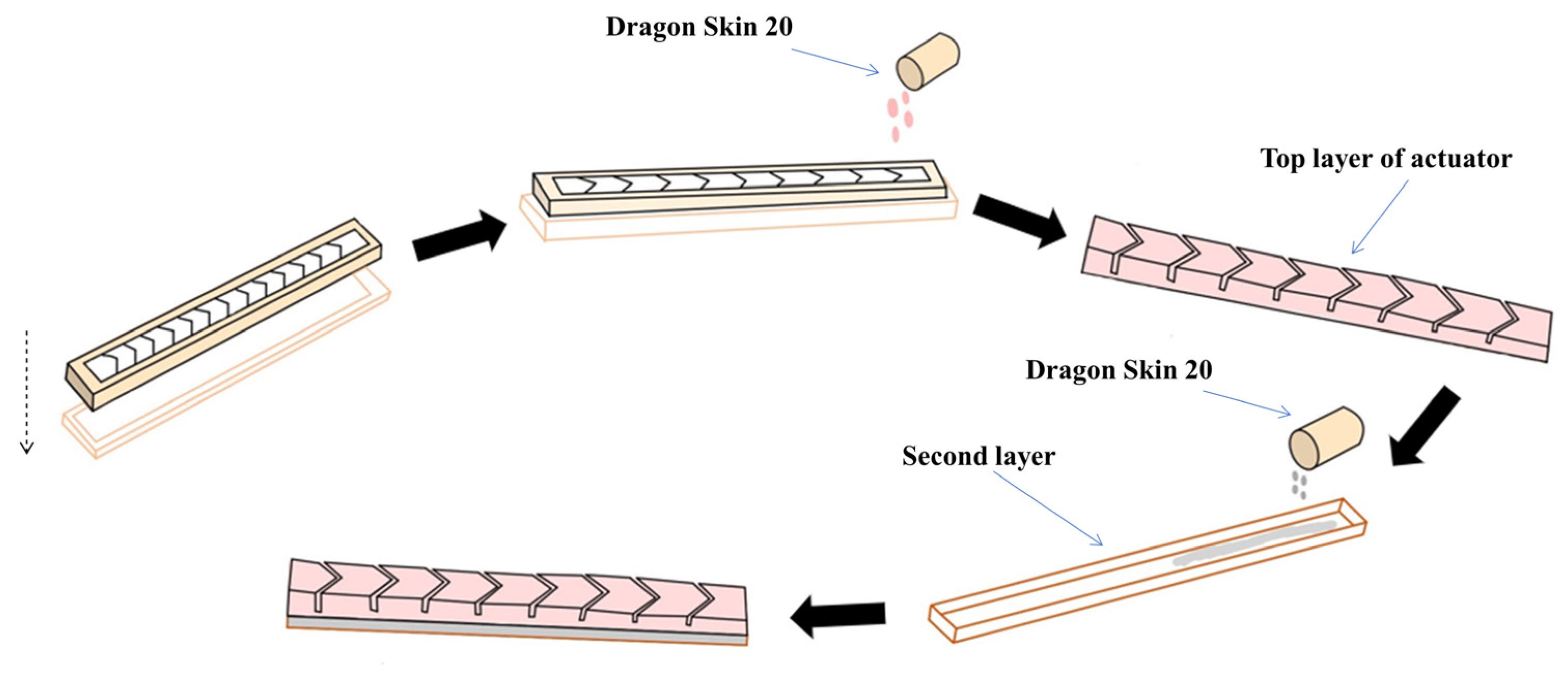
Figure 8.
The result of the workspace analysis. (Top) The computed workspace for the 45° angled actuator. The different colors in the images are the plotted value of the tracked reference point (tip) of the actuator under different pressure configurations (see legend in the picture). The grayed area, instead, is the computed workspace using the simulation data. (Bottom) Three views of the same workplace: front (YZ plane), side (XZ plane), and bottom (XY plane).

Figure 9.
The experimental setup (A) and the grasped object during the force measurements (B–F).

Figure 10.
Force profile for the different tested objects with highlights in the particular moment of each profile. The fluctuations in force arise from the actuator sliding and adjusting to the objects.
Figure 10.
Force profile for the different tested objects with highlights in the particular moment of each profile. The fluctuations in force arise from the actuator sliding and adjusting to the objects.

Table 1.
Parameter value for the design of the simulated actuators.
| Symbol | Value |
|---|---|
| L | 260 mm |
| H | 20 mm |
| W | 25 mm |
| f | 10 mm |
| fi | 4 mm |
| d | 1.5 mm |
| t0 | 2 mm |
| ti | 1.5 mm |
| l | 15.8 mm |
| l0 | 14.8 mm |
Disclaimer/Publisher’s Note: The statements, opinions and data contained in all publications are solely those of the individual author(s) and contributor(s) and not of MDPI and/or the editor(s). MDPI and/or the editor(s) disclaim responsibility for any injury to people or property resulting from any ideas, methods, instructions or products referred to in the content. |
© 2023 by the authors. Licensee MDPI, Basel, Switzerland. This article is an open access article distributed under the terms and conditions of the Creative Commons Attribution (CC BY) license (https://creativecommons.org/licenses/by/4.0/).
Share and Cite
MDPI and ACS Style
Shahabi, E.; Kamare, B.; Visentin, F.; Mondini, A.; Mazzolai, B. Design of Soft Pneumatic Actuator with Two Oblique Chambers for Coupled Bending and Twisting Movements. Actuators 2023, 12, 446. https://doi.org/10.3390/act12120446
AMA Style
Shahabi E, Kamare B, Visentin F, Mondini A, Mazzolai B. Design of Soft Pneumatic Actuator with Two Oblique Chambers for Coupled Bending and Twisting Movements. Actuators. 2023; 12(12):446. https://doi.org/10.3390/act12120446
Chicago/Turabian StyleShahabi, Ebrahim, Behnam Kamare, Francesco Visentin, Alessio Mondini, and Barbara Mazzolai. 2023. "Design of Soft Pneumatic Actuator with Two Oblique Chambers for Coupled Bending and Twisting Movements" Actuators 12, no. 12: 446. https://doi.org/10.3390/act12120446
Note that from the first issue of 2016, this journal uses article numbers instead of page numbers. See further details here.