
Tendon-Driven Gripper with Variable Stiffness Joint and Water-Cooled SMA Springs
by
 , , ,
, , ,
Phuoc Thien Do
,
Quang Ngoc Le
*,
Quoc Viet Luong
*,
Hyun-Ho Kim
,
Hyeong-Mo Park
and
Yeong-Jin Kim
* Department of Mechanical Engineering, Incheon National University, Incheon 22012, Republic of Korea
*
Authors to whom correspondence should be addressed.
Actuators 2023, 12(4), 160; https://doi.org/10.3390/act12040160
Submission received: 1 March 2023
/
Revised: 24 March 2023
/
Accepted: 2 April 2023
/
Published: 4 April 2023
(This article belongs to the Section Actuators for Robotics)
Abstract
:In recent years, there has been an increase in the development of medical robots to enhance interventional MRI-guided therapies and operations. Magnetic resonance imaging (MRI) surgical robots are particularly attractive due to their ability to provide excellent soft-tissue contrast during these procedures. This paper describes a novel design for a tendon-driven gripper that utilizes four shape memory alloy (SMA) spring actuators and variable stiffness joints controlled by SMA coils for use in MRI surgical robot applications. The contact force of the gripper link is determined by the mechanical properties of the SMA spring actuators (SSA) and the angle of each linkage, and the joint stiffness can be adjusted by varying the electrical current applied to the SMA coil. To enhance the efficiency of the SSAs, a new cooling system using water has been proposed and implemented. To validate the effectiveness of our proposed gripper, we conducted three types of experiments, namely, a single SSA experiment, a single SMA coil experiment, and a whole gripper experiment. The experimental results demonstrate that the proposed water-cooling system can effectively solve temperature issues of SMA, and the joint stiffness in the austenite state is higher than that in the martensite state. Moreover, our experiments show that the presented gripper is capable of grasping and holding objects of various shapes and weights.
1. Introduction
Medical imaging systems have been used in robotic surgery for a long time to enable more precise procedures such as resections. Computed tomography (CT), magnetic resonance imaging (MRI), and ultrasound (US) are examples of imaging systems that can be utilized to enhance surgical performance when combined with surgical robots. MRI is particularly beneficial for tumor surgery as it offers several advantages, including excellent soft-tissue contrast, high temporal and spatial resolution, multiplane scanning capability, and real-time tissue and instrument tracking [1]. To date, for electrocautery and suction tools, snake or needle-shaped MRI surgical robots have been developed, but grippers have not been extensively explored [2,3,4,5]. Gripping and placing objects, including organs, is a fundamental function of robotic manipulators. As the end effector, grippers play a crucial role in the surgical robot system. They act as temporary mechanical interfaces between the manipulators and the grasped objects, such as human organs and resected target tissue. To successfully perform grasping tasks, grippers must hold objects stably to prevent slipping and damaging the objects. Grippers need to be diverse in shapes, sizes, and materials, as well as in strategies, control algorithms, and even sensors, to ensure precise gripping [6]. Each application requires a suitable end effector, making the selection of an appropriate gripper essential [7]. In addition, grippers often require stiffness control or shape adjustment, depending on the stiffness of the organ or resected tissue.
For industrial applications, vacuum-based grippers are among the most commonly used grippers [8,9,10,11,12]. Utilizing the suction effect, some vacuum-based cube-shaped grippers with surface contact have been developed for grasping objects [13,14]. Although vacuum-based grippers have shown powerful performance in industrial applications, they also have limitations, such as the potential to cause damage to delicate human organs. As an alternative, soft robot grippers have recently gained attention from researchers due to their adjustable gap between the target object and the gripper, allowing for a better fit with the shape of the target. To address the issue of damaging grasped objects, various soft robotic designs have been proposed, tailored to specific application requirements.
Selecting the appropriate soft actuator for a gripper is crucial as it affects the overall grasping performance, including force and speed. Compact and lightweight robotic systems necessitate the use of soft and intelligent actuators [15]. Extensive research has focused on numerous functional materials to develop actuators that possess both flexibility and high force capability [16,17]. The materials employed in the gripper also need to be compatible with the electromagnetic field of the surgical robot system in an MRI environment. However, most metals produce MRI noise, rendering them unsuitable for use as MRI surgical robot materials. Several MRI-compatible materials have been proposed, including brass [18] and shape memory alloys (SMAs) [2,3,4,19], silicone rubber [20], and plastics [3], all of which have been utilized in MRI-guided surgical robots. Compared to the aforementioned actuator alternatives, the distinctive mechanical properties of SMA actuators make them a strongly recommended option for the proposed gripper.
SMAs have attracted scientists’ attention due to their various applications to change the stiffness of manipulators or actuators in soft robotics. These materials can recover their original shape when subjected to a specific stimulation, such as heat or magnetism [21]. Currently, SMAs come in various shapes, namely spring [22], film [23], wire [24], and even foam [25]. Research has been conducted on the use of SMA springs in gripper actuation. According to [26], Roshan et al. designed a gripper that employs an SMA spring as the primary actuator to drive the gripper links, making it suitable for minimally invasive surgery. The SMA spring pulls a linear guide attached to a gripper finger to convert linear into angular motion. The gripper jaws and the mechanism’s casing are fabricated using 3D printing technology, simplifying the process. However, the paper did not address the cooling solution for the SMA spring, which is a critical aspect when using SMA as a primary actuator. Water cooling for the SMA spring was developed by Cheng et al. [27] by threading a silicone tube through it.
This paper proposes a two-jaw, tendon-actuated gripper utilizing SMA spring actuators and an SMA coil that can change its stiffness. Our proposed robot has a relatively simple structure that includes an SMA coil inserted into a joint composed of two links for joint stiffness control. The SMA coil is used as an actuator that applies a strong tightening force for friction generation between the links when a current is applied. To overcome the temperature issues commonly associated with SMA materials, a novel cooling system design is introduced. The SMA springs are enclosed within silicone tubes featuring a saw-tooth profile. The proposed actuator is characterized by a compact design, lightweight construction, and fast reaction time. The remainder of this paper is organized as follows: Section 2 provides a detailed description of the gripper’s conceptual design, followed by an overview of the silicone cover fabrication process. The gripper finger and its corresponding features are also presented in this section. Section 3 outlines the mechanical properties of the SMA spring, and the contact force generated by a single finger on an object. Section 4 offers insight into the experimental methods employed and the outcomes of single-actuator testing. In addition, the experimental setup and results of the grasping test are presented in this section. Finally, this paper concludes in Section 5.
2. Materials and Methods
2.1. Design of the Tendon-Driven Gripper
This section outlines the structure of the proposed end-effector for the robotic arm. The primary constituents of the robot include four silicone SMA actuators (SSAs), two fingers (jaws), a gripper frame, and four tendons, as can be seen in Figure 1. The gripper frame functions as the anchor point for all the components and serves as a crucial interface between the robotic arm and the end-effector. Two fingers are attached to the gripper base, and the surface gap between them is 38 mm in the rest state. The SSA act as the driving force for the end-effector’s fingers, using the attached tendons based on the characteristics of the SMA spring. When it is in a lower temperature (martensite state), it can easily stretch out. When the SMA spring is heated to a high temperature (austenite state), it will recover its original shape. Therefore, the SSAs 2 and 3 produce linear motion (axial motion) to pull the tendons of the fingers and make them bend in a direction that can grasp and hold objects when SSAs 2 and 3 are in the austenite state, and the SSAs 1 and 4 are in the martensite state, as depicted in Figure 1c. Similarly, the SSAs 1 and 4 also generate motion to pull the tendons of the fingers and make them bend in a direction that can drop objects when SSAs 1 and 4 are in the austenite state, and the SSAs 2 and 3 are in the martensite state, as shown in Figure 1d. Moreover, SSAs 1 and 4 make the parallel fingers extend the gap of the silicone pads, which allows them to grasp targets with a large dimension. In terms of controlling the four SSAs, each actuator has its independent controller system, and it is described in detail in the experimental setup section. The SSAs are described in Section 2.2.
Additionally, a silicone pad is attached to the end effector of each finger to increase the gripping ability. The retention of objects by grippers is typically achieved through contact with the object’s surface. The selection of contact methods depends on the object and gripper contact surfaces. Geometric contact methods include points, lines, and surfaces. Surface contact is frequently preferred since it offers the most extensive contact area, thereby maximizing the grip pressure of the gripper. The finger jaws are designed with the SMA coil to adjust the joint stiffness for stably holding an abject, as described in Section 2.3.
2.2. Conceptual Design of Silicone SSAs
The mechanical and electrical connections of the SSAs are illustrated in Figure 2. The SMA spring is attached to two M3 screw hooks by wrapping copper wire around them and soldering them with tin. As the SMA spring is a conductive material that changes phase when heated, an electric current is utilized to induce heating. The electric wires are connected to the SMA spring at the ends of the spring with soldering joints. To measure the actual temperature of the spring, a thermistor sensor is placed on the first coil of the spring. Additionally, in order to prevent direct contact with water during the cooling process, the sensor is covered with a small block of silicone. The silicone chamber, as well as the cooling channel of the SMA spring, is inspired by the expanding soft robotics [28,29,30] with a wall thickness of 1 mm; it has one degree of freedom in space (axial movement). The material of the air chamber is made of silicone called Dragon Skin [24] with a hardness of 10 Shore A. The soft silicone cover is fabricated by silicone die casting, and the fabrication process is essentially similar to [31]. According to [31], the prototype is divided into two parts which are the products of the casting process. To reduce the fabrication process time, we design one single mold for the casting without separating them into two casting products. The mold is designed based on the 3D pre-designed prototype profile (inside and outside), and it is then manufactured by using a 3D printer. The M3 screw hooks, which attach to the ends of the spring, connect to the plastic caps by threads. One cap on the left of the SSA is fixed on the gripper frame, and the other links to a tendon to actuate the gripper. Because of water cooling, there are two silicone tubes (inlet and outlet) with an outer diameter of 3 mm connecting to the SSA.
2.3. Design of the Gripper Jaw with Stiffness Control
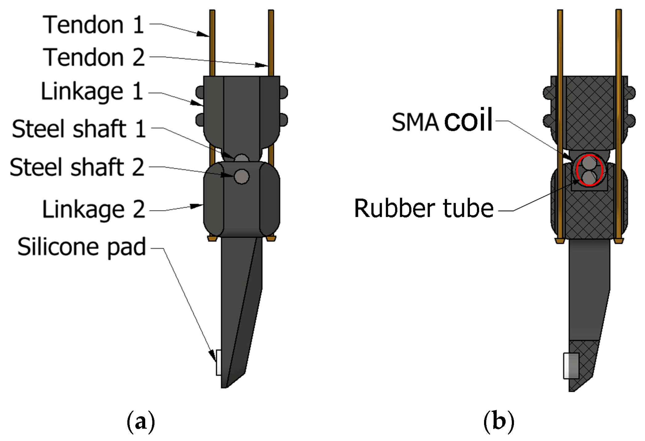
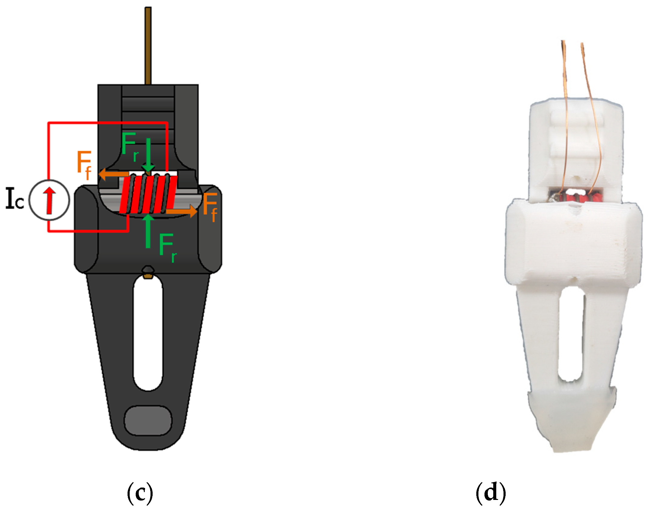
The finger shown in Figure 3a was inspired by a surgical robot that can change its joint stiffness [32]. The finger was 3D-printed using polylactic acid (PLA) and had revolute joints linking the entire finger, with each finger actuated by two tendons. Figure 3a,b illustrate the robot link’s structure with two linkages and a rotational joint. To increase the grasping ability of the tendon-driven gripper, a silicone pad is attached to the end effector linkage. Figure 3c illustrates the austenite state of the SMA coil. To vary the stiffness of the gripper joint, an SMA spring with four coils wraps two shafts of two linkages together. In order to prevent a short circuit between the conductive SMA spring and steel rod, a rubber tube is placed between the SMA coil and shafts. Once the SMA spring reaches the austenite phase, it transforms into its original shape. However, frictional forces (Ff) acting on the spring may impede the restoration process of the SMA spring. Moreover, as the inner diameter of the spring is smaller than the diameter of the sum of two adjacent shafts at the austenite state, the spring exerts a compressive force, resulting in a tightening effect (Fr). Finally, the fixed base of the finger has a groove on two sides for easy assembly with the gripper’s frame, making it a modular design. The prototype of the gripper jaw is depicted in Figure 3d.
3. Gripper Modeling
3.1. Mechanical Properties of the SMA Spring
The performance parameters of the SMA spring used in this paper are shown in Table 1. SMA springs can transform from martensite to austenite by heating and cooling it. SMA springs have various elastic moduli in the martensitic and austenitic states. When the SMA is designed as a spring, its stiffness changes following the equation in [33]:
where d is the wire diameter, D is the coil diameter, n is the number of coils, EM is the martensite elastic modulus, and EA is the austenite elastic modulus.
The stretch of the spring under load F can be expressed as:
where G(T) is the shear modulus of the SMA spring that is estimated from experiment results in Section 4.1.2. Therefore, when TM ≤ T ≤ TA, the axial load at temperature T is expressed as:
when the axial displacement of the SMA spring is restricted, the compressed length of the SMA spring is kept as:
when TM ≤ T ≤ TA, the output force at temperature T can be obtained from (3) and (4) as:
3.2. Contact Force of Single Gripper Finger
Assuming that the gripper is holding an object with a dimension of D, as shown in Figure 4, and is actuated by a pair of SMA springs via tendons, the tendon forces of the second linkage can be expressed as:
where F3 denotes the pulling force of Spring 2 at the austenite state, and F1 represents the pulling force of Spring 1 at the martensite state. F1 and F3 can be calculated from Equation (5). The equations denote that G™ represents the shear modulus of SMA spring of SSAs 1, whereas δL1 signifies the displacement of SSAs 1. Similarly, G(TA) represents the shear modulus of SMA Spring 2 of the SSAs 2, and δL2 indicates the displacement of the SSAs 2. The moment M, which induces rotation of the second linkage when the SMA spring of the SSAs 1 is in the martensite state and the SMA spring of the SSAs 2 is in the austenite state, can be expressed as:
where a is the distance from the midpoint of the revolute joint to the point where the tendon intersects it perpendicularly.
The resulting moments, M1 and M2, are induced by the forces F2 and F4, respectively. Moreover, F1 has a lower magnitude compared to F3. The difference in the values of F1 and F3 can be attributed to the fact that G(TA) is higher than G(TM). Finally, the contact force FE at the red point can be obtained from Equations (5)–(10):
where l is the distance from the midpoint of the revolute joint to the contact point.
4. Experiment and Results
4.1. The Characteristics of the SSAs Experiment
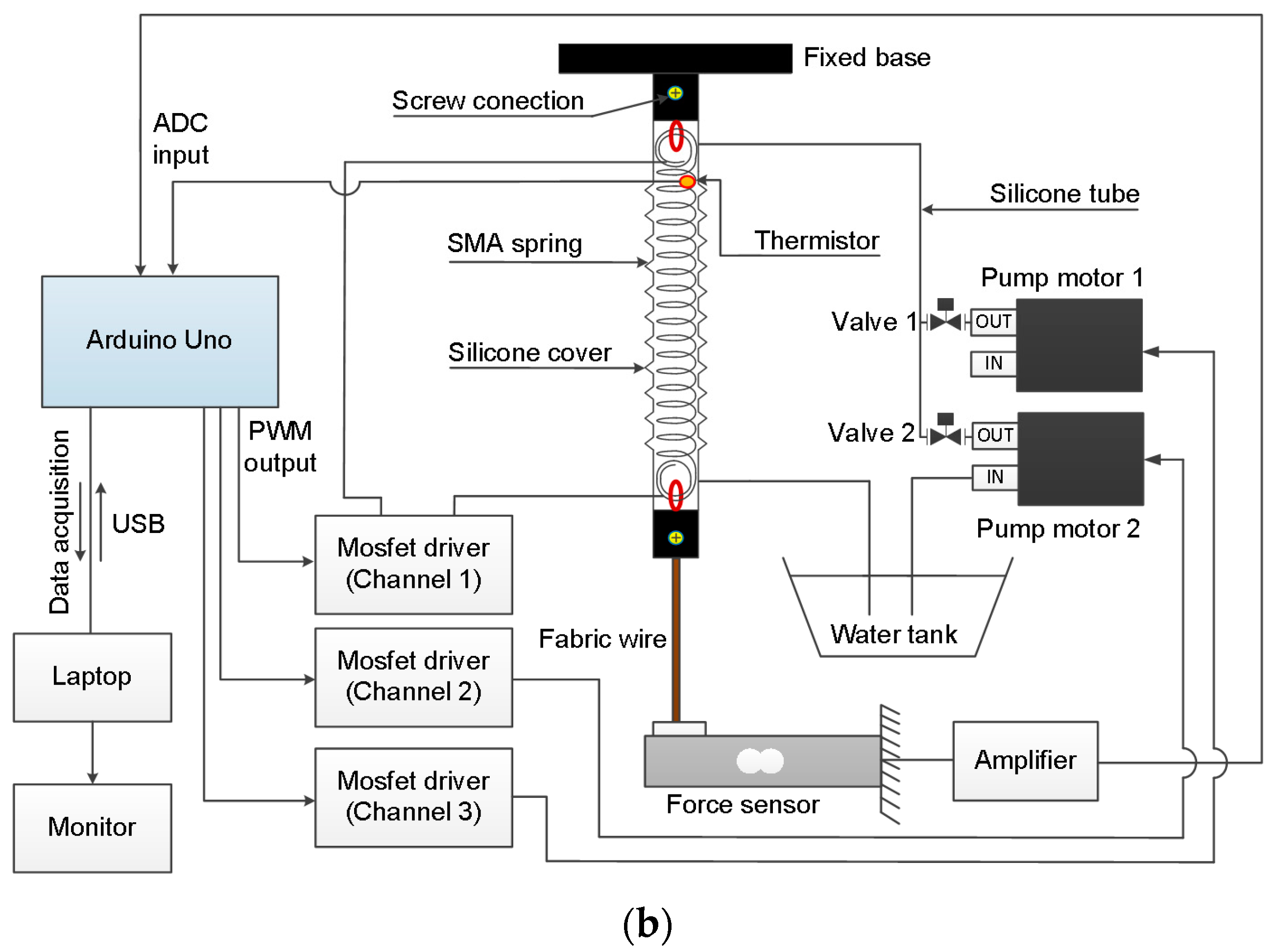
The force measurement experiment aimed to measure the force generated by a single SSA, and the experiment setup is shown in Figure 5a. A metal wire hangs one head of the SSAs on an aluminum frame. Due to the low output voltage of the force sensor, this device amplifies the load cell signal. In addition, a load cell sensor (Model 333ALB, Ktoyo Co., Ltd., Seoul, Republic of Korea) attaches to the other head of the SSA and converts the mechanical stress into voltage. The thermoelectric Peltier cooler is utilized to decrease the cooling water temperature in the water tank. The 4-channel MOSFET driver plays a role in controlling the SSA and two water pump motors, and the power supply for it is 5 V. In order to clarify how the system works, the schematic diagram shown in Figure 5b illustrates the entire system’s hardware connections. The Arduino Uno measures the force of the single SSA with the analog-digital converter (ADC) module through the amplifier. SMA springs have low resistance and are conductive materials, so they need a controller to control the electric current going through the springs. Therefore, a simple proportional-integral-derivative (PID) controller is proposed to control the voltage and temperature of the SMA spring in this study.
The temperature control algorithm (Figure 6) was implemented with an Arduino Uno with a sample time of 500 milliseconds. A PID control algorithm was used to control the temperature of the SMA spring based on the difference between the heat transfer from the spring to the thermistor and the desired value. Unlike other process values such as speed, angle, and force of a motor or brightness of a light, the temperature cannot automatically decrease itself even after stopping applying current on the spring. Thus, the combination between the PID controller and the water cooling could be the solution for the temperature issue.
When the temperature is set at a desired value with a higher temperature, the PID control “wakes up”. When the temperature is set at a desired value with a lower temperature, the PID control “goes to sleeping mode”. Therefore, Water Pump Motor 2 is activated by the MOSFET driver (channel 2), and Valve 2 also opens; Valve 1 and Water Pump Motor 1 do not work. When the temperature reaches the desired value, Valve 2 and Water Pump Motor 2 stop working. In the system, Pump 1 and Valve 1 work together to release all the water inside the SSA after it has been cooled using water. Compressed air is used to pump the water out. Arduino reads the voltage from the thermistor and the loadcell and converts them into temperature and force, respectively.
In order to determine the SSA’s characteristics and verify the effectiveness of a single SSA, three types of experiments were set up and executed:
- The first experiment aims to verify the effectiveness of the water-cooling system, so many experiments of the SSA with and without the water-cooling system are executed.
- In the second experiment, the axial force of a single SSA is measured and the shear module of the spring is then estimated.
- The general force of a single gripper is measured and the experiment results are then compared to the mathematical model in the final experiment.
These experiments provide valuable insights into the SSA’s characteristics and help to confirm its effectiveness in the context of a soft robotic gripper.
4.1.1. The Response Time of the Cooling System
For this experiment, a single SSA actuator was employed, along with the experimental setup shown in Figure 5, with the room temperature at 24 °C. Initially, we set the desired temperature to 27 °C and waited to stabilize at that temperature before proceeding. Subsequently, the desired temperature was set to 50 °C. As illustrated in Figure 7, the initial stages of both elevated temperature processes were almost identical. However, at a set temperature of 30 °C, the temperature of the SMA spring with water cooling experienced a dramatic reduction, whereas the spring with natural cooling exhibited only a slight decrease. This indicates that the proposed water-cooling system is significantly more efficient than the natural one. The PID controller was utilized to regulate the temperature of the SSA. Under the reference temperature was 50 °C, the process temperature went up from 27 °C to 50 °C linearly in 15 s.
4.1.2. Shear Modulus Estimation
The experimental results of four separate trials for a single SSA are illustrated in Figure 8. Besides, the mathematical model of the axial force exerted by the SSA, as derived in Equation (5), is also presented. One end of the SSA was mounted onto the fixed base, and the other one was connected to the force sensor via a fabric wire with a spring displacement of 90mm. The spring displacement must be fixed because it influences the spring force. The result shows that the axial force-temperature curves are nearly similar in the ten random tests. The relationship between force and temperature is supposed to be linear, so it is derived from a linear equation. In terms of force output, the maximum axial force achievable by the SMA spring actuator is 500 gf, with a corresponding temperature of 50 °C. As mentioned early, this experiment aims to determine the shear modulus G(T) of the SMA spring via F(T) in Equation (5). We measured the axial force ten times and obtained the average force. Afterward, the relationship between temperature and the average axial force can be expressed by an interpolated equation, given as:
Therefore, the shear modulus can be expressed as a function of temperature:
where T is the temperature in the spring with the initial condition F(28 °C) = 0 N. After estimating the shear modulus, the generated force of the gripper is calculated following Equation (9).
4.1.3. Survey the Contact Force of a Gripper Finger
This experiment aims to assess the accuracy of the proposed mathematical model described in Equation (9) for determining the contact force of the gripper link to objects. The shear modulus can be determined via Equation (11). To attain the maximum gripping force, the angle (θ) of the gripper link was set to zero. Therefore, the position of the load cell was adjusted to achieve a theta zero degree as shown in Figure 9a. Subsequently, the temperature was gradually raised in steps of 1 °C and the highest test temperature was 55 °C. The experimental result shown in Figure 9b indicates that the proposed mathematical model could predict the contact force of the gripper link. However, the experimental data obtained some errors with the derived equation. These discrepancies may be attributed to the delay in heat transfer to the thermistor, which made the experimental data higher than the mathematical one.
4.2. The Characteristics of the Joint Stiffness
One of the purposes of the variable stiffness joints is to allow the gripper to maintain a secure hold on an object without requiring significant pulling force from the SSAs. To ensure the optimal functioning of robotic systems, it is crucial to adapt their stiffness to various application scenarios. Consequently, it is essential to investigate the range and maximum stiffness values to determine the optimal parameters for the system. This study aimed to evaluate the variable stiffness mechanism and measure the force influenced by a single gripper finger when the adjacent shafts are tightened by coil-twisting of the SMA spring in both the martensite and austenite states. The joint stiffness is affected by the tightening force of the SMA coil, and the spring temperature affects the coil-twisting pressure. Thus, the stiffness of the joint depends on the SMA coil temperature. In the experimental setup shown in Figure 8a, the finger was placed horizontally, and a fabric wire for hanging the load was attached to the end edge of the jaw to hang the scale weights. The angle denoted by Theta 1 represents the change in angle when a load is applied to the wire, as compared to its original angle. Based on the proposed link, it has been determined that the maximum angle measured is 13 degrees. We put the scale weights onto the fabric wire until it bends to the maximum angle.
The experimental results presented in Figure 8b indicate that the joint stiffness is higher in the austenite state than in the martensite state. During the experimental procedure, a current of 1 A and a voltage of 2 V were applied to the SMA coil in the finger. The scale weight was gradually increased by 10 g until the finger reached its maximum bending angle. The results showed that in the martensite state, the finger could withstand the heaviest load of 50 g. In contrast, in the austenite state, the finger could support a maximum load of 90 g. Therefore, the ratio between the heaviest loads the finger could withstand in the austenite and the martensite state was approximately two times higher. This difference in force behavior between the martensite and austenite states can be attributed to the change in stiffness of the SMA spring caused by the phase transition from martensite to austenite. The SMA coil in the martensite state is more flexible due to the formation of the martensite phase, resulting in lower friction on the pair of shafts and obtaining a lower load (low coil-twisting pressure). Conversely, the SMA spring is stiffer in the austenite state (high coil-twisting pressure), resulting in higher friction on the rods, which resists the rotation of the robot joint. Therefore, the austenite state of the SMA spring shows a higher load than the martensite state. The experimental results presented in Figure 10.
4.3. Gripper Experiment
4.3.1. Experimental Setup
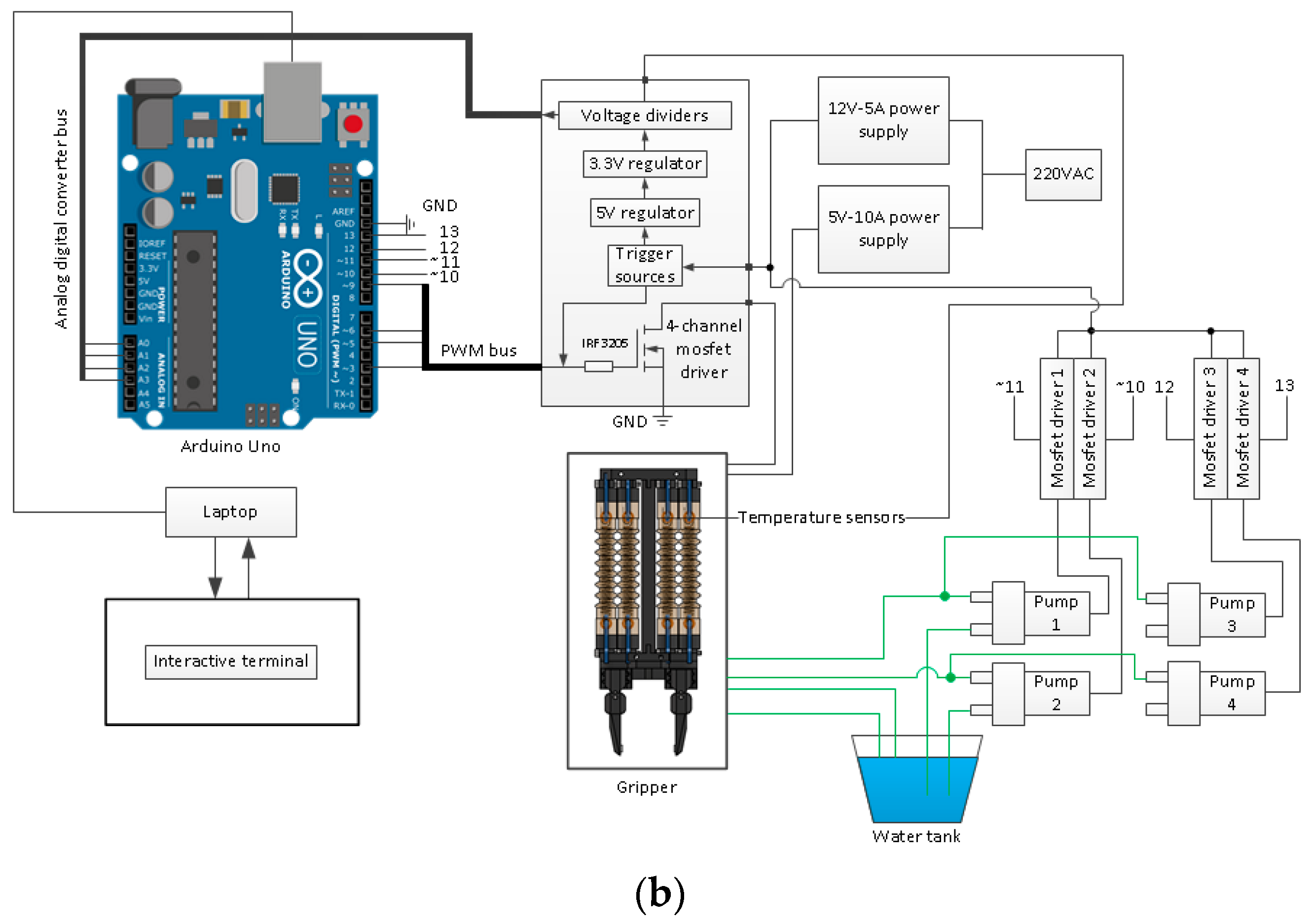
As one of the most significant components of a manipulator, the proposed gripper is mainly designed to clamp objects of various shapes, sizes, and weights. Two fingers and four silicone SSAs were integrated into the gripper frame, and the fingers were installed on the gripper frame by grooves. Grasping tests on different shapes, sizes, and materials were carried out using the two-finger grippers. Testing was performed to determine the gripping ability of the proposed gripper, and Figure 11 shows the experiment setup. There are four SSAs mounted onto the gripper frame to actuate the fingers, so there are also four PID controllers for each actuator. The PID controller algorithm for the proposed gripper is similar to Figure 6.
4.3.2. Experimental Results
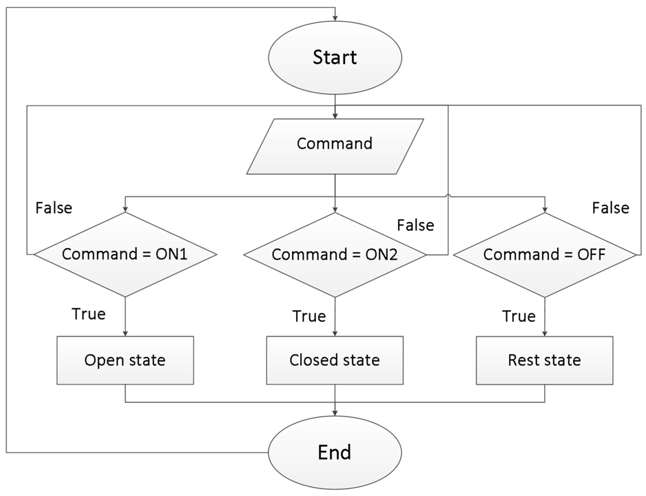
Figure 12a–c illustrate the gripper in its rest, open, and closed states. When the gripper expands, the maximum size it can grip is around 38 mm. The experimental process started with the extending jaw. After an object had been placed between two links, Pump 2 and Pump 4 were activated to remove all water from the SSA. The gripper then turned into the grasping mode, gripped, and held a target for ten seconds. Finally, it turned into the rest mode to drop the object down to the ground by pumping water to the actuators for cooling them. Figure 13 presents the working diagram of the gripper, and the data are input directly to the command window of the Arduino IDE. The grasping ability of the gripper depends on the shape and weight of the targets; also, the temperature of the actuators affects the robot’s working capacity. Therefore, depending on the object, the grasping temperature will be different.
The experiment evaluated the grasping performance of the proposed tendon-driven gripper by conducting ten pick-and-drop tests for each object on an aluminum profile frame. A lift lasting for 10 s without dropping was considered a successful grasp. The grasping snapshots captured using the gripper are shown in Figure 12d–i, while the grasping targets, their dimensions, weights, and corresponding successful grasping temperatures are listed in Table 2. The results showed that the gripper could stably grasp, hold, and drop various objects with different weights and shapes, including three scale weights, an egg, a battery, and a charger. The investigation found that the grasping force of an actuator could increase with the distance between the center of the finger and the tendon. However, this distance also leads to an increase in the size of the finger proportionally.
The experimental results indicate that the performance of the proposed gripper is significantly influenced by the temperature supplied to the SSAs, with a higher temperature resulting in the gripper being able to grasp and hold objects with higher weights. The grasping ability of the gripper is also affected by the surface roughness of the grasping targets, as different materials exhibit varying degrees of roughness. Therefore, as a solution for this issue, a silicone pad was used for each finger, effectively increasing the gripper’s grasping capacity. The silicone pads, which are softer than the gripper’s hard links, resulted in the gripper being called a “hybrid gripper”. Furthermore, the gripper’s ability to hold targets steadily without deforming them is attributed to its rigid links, which prevent excessive deformation during grasping. These findings demonstrate the potential of the proposed gripper design for applications that require stable and reliable grasping of objects with various weights and surface characteristics.
5. Conclusions
This study presents the two-jaw tendon-driven gripper equipped with four SMA actuators and two SMA coils for enhancing the grasping ability of various objects. To control the temperature of the four SMA actuators, a temperature controller and a water-cooling system are implemented, resulting in shorter cooling times than natural cooling. The SMA spring does not influence the force and displacement of the spring. The highest axial force that an SSA can produce is 500 gf at 50 °C. The joint stiffness is observed to be higher during the austenite state of the SMA coil compared to the martensite state. In particular, the gripper finger could withstand a maximum load of 90 g in the austenite state and 50 g in the martensite state, representing a 2 times higher load capacity in the austenite state. Picking and holding the experiment items was conducted to test the grasping ability of the gripper, and it successfully grasped all the tested objects. The proposed gripper’s system is simple and utilizes only electricity to heat the spring without using any external heating source. Our findings suggest that the proposed gripper design can be useful for various surgical robot applications that require a high degree of grasping accuracy and efficiency.
Author Contributions
Conceptualization, Y.-J.K., Q.N.L. and P.T.D.; methodology, P.T.D.; writing—original draft preparation, Y.-J.K. and P.T.D.; experiment, P.T.D., H.-H.K. and H.-M.P.; writing—review and editing, Y.-J.K., Q.N.L., Q.V.L. and P.T.D. All authors have read and agreed to the published version of the manuscript.
Funding
This work was supported by Incheon National University Research Grant in 2018.
Data Availability Statement
Data sharing is not applicable to this article.
Conflicts of Interest
The authors declare no conflict of interest.
References
- Farooq, M.U.; Seong, Y.K. A Decade of MRI Compatible Robots: Systematic Review. IEEE Trans. Robot. 2022, 1–23. [Google Scholar] [CrossRef]
- Kim, Y.; Cheng, S.S.; Desai, J.P. Active Stiffness Tuning of a Spring-Based Continuum Robot for MRI-Guided Neurosurgery. IEEE Trans. Robot. 2017, 34, 18–28. [Google Scholar] [CrossRef] [PubMed]
- Kim, Y.; Cheng, S.S.; Diakite, M.; Gullapalli, R.P.; Simard, J.M.; Desai, J.P. Toward the Development of a Flexible Mesoscale MRI-Compatible Neurosurgical Continuum Robot. IEEE Trans. Robot. 2017, 33, 1386–1397. [Google Scholar] [CrossRef] [PubMed]
- Cheng, S.S.; Kim, Y.; Desai, J.P. New Actuation Mechanism for Actively Cooled SMA Springs in a Neurosurgical Robot. IEEE Trans. Robot. 2017, 33, 986–993. [Google Scholar] [CrossRef] [PubMed]
- Monfaredi, R.; Cleary, K.; Sharma, K. MRI Robots for Needle-Based Interventions: Systems and Technology. Ann. Biomed. Eng. 2018, 46, 1479–1497. [Google Scholar] [CrossRef]
- Zhang, B.; Xie, Y.; Zhou, J.; Wang, K.; Zhang, Z. State-of-the-art robotic grippers, grasping and control strategies, as well as their applications in agricultural robots: A review. Comput. Electron. Agric. 2020, 177, 105694. [Google Scholar] [CrossRef]
- Samadikhoshkho, Z.; Zareinia, K.; Janabi-Sharifi, F. A Brief Review on Robotic Grippers Classifications. In Proceedings of the 2019 IEEE Canadian Conference of Electrical and Computer Engineering (CCECE), Edmonton, AB, Canada, 5–8 May 2019; IEEE: New York, NY, USA, 2019; pp. 1–4. [Google Scholar]
- Gabriel, F.; Fahning, M.; Meiners, J.; Dietrich, F.; Dröder, K. Modeling of vacuum grippers for the design of energy efficient vacuum-based handling processes. Prod. Eng. 2020, 14, 545–554. [Google Scholar] [CrossRef]
- Zhang, H.; Peeters, J.; Demeester, E.; Kellens, K. A CNN-Based Grasp Planning Method for Random Picking of Unknown Objects with a Vacuum Gripper. J. Intell. Robot. Syst. 2021, 103, 64. [Google Scholar] [CrossRef]
- Matsuo, I.; Shimizu, T.; Nakai, Y.; Kakimoto, M.; Sawasaki, Y.; Mori, Y.; Sugano, T.; Ikemoto, S.; Miyamoto, T. Q-bot: Heavy object carriage robot for in-house logistics based on universal vacuum gripper. Adv. Robot. 2020, 34, 173–188. [Google Scholar] [CrossRef]
- Schaffrath, R.; Jäger, E.; Winkler, G.; Doant, J.; Todtermuschke, M. Vacuum gripper without central compressed air supply. Procedia CIRP 2021, 97, 76–80. [Google Scholar] [CrossRef]
- Jamaludin, A.S.; Razali, M.N.M.; Jasman, N.; Ghafar, A.N.A.; Hadi, M.A. Design of Spline Surface Vacuum Gripper for Pick and Place Robotic Arms. J. Mod. Manuf. Syst. Technol. 2020, 4, 48–55. [Google Scholar] [CrossRef]
- Tahir, A.M.; Zoppi, M.; Naselli, G.A. PASCAV Gripper: A Pneumatically Actuated Soft Cubical Vacuum Gripper. In Proceedings of the 2018 International Conference on Reconfigurable Mechanisms and Robots (ReMAR), Delft, The Netherlands, 20–22 June 2018; IEEE: New York, NY, USA, 2018; pp. 1–6. [Google Scholar]
- Brown, E.; Rodenberg, N.; Amend, J.; Mozeika, A.; Steltz, E.; Zakin, M.R.; Lipson, H.; Jaeger, H.M. Universal robotic gripper based on the jamming of granular material. Proc. Natl. Acad. Sci. USA 2010, 107, 18809–18814. [Google Scholar] [CrossRef] [Green Version]
- Sun, Y.; Liu, Y.; Pancheri, F.; Lueth, T.C. LARG: A Lightweight Robotic Gripper With 3-D Topology Optimized Adaptive Fin-gers. IEEEASME Trans. Mechatron. 2022, 27, 2026–2034. [Google Scholar] [CrossRef]
- Lee, C.; Kim, M.; Kim, Y.J.; Hong, N.; Ryu, S.; Kim, H.J.; Kim, S. Soft Robot Review. Int. J. Control Autom. Syst. 2017, 15, 3–15. [Google Scholar] [CrossRef]
- Miriyev, A.; Stack, K.; Lipson, H. Soft material for soft actuators. Nat. Commun. 2017, 8, 596. [Google Scholar] [CrossRef] [PubMed] [Green Version]
- Ho, M.; Kim, Y.; Cheng, S.S.; Gullapalli, R.; Desai, J.P. Design, development, and evaluation of an MRI-guided SMA spring-actuated neurosurgical robot. Int. J. Robot. Res. 2015, 34, 1147–1163. [Google Scholar] [CrossRef] [PubMed] [Green Version]
- Kim, Y.; Desai, J.P. Design and kinematic analysis of a neuro- surgical spring-based continuum robot using SMA spring ac-tuators. In Proceedings of the 2015 IEEE/RSJ International Conference on Intelligent Robots and Systems (IROS), Hamburg, Germany, 28 September–2 October 2015; pp. 1428–1433. [Google Scholar]
- Cianchetti, M.; Ranzani, T.; Gerboni, G.; De Falco, I.; Laschi, C.; Menciassi, A. STIFF-FLOP surgical manipulator: Mechanical design and experimental characterization of the single module. In Proceedings of the 2013 IEEE/RSJ International Conference on Intelligent Robots and Systems, Tokyo, Japan, 3–7 November 2013; pp. 3576–3581. [Google Scholar] [CrossRef]
- Mohd-Jani, J.; Leary, M.; Subic, A.; Gibson, M.A. A review of shape memory alloy research, applications and opportunities. Mater. Des. 2014, 56, 1078–1113. [Google Scholar] [CrossRef]
- Sobrinho, J.M.; Filho, F.; Emiliavaca, A.; Cunha, M.F.; Souto, C.R.; Silva, S.; Ries, A. Experimental and numerical analyses of a rotary motor using shape memory alloy mini springs. Sens. Actuators A Phys. 2020, 302, 111823. [Google Scholar] [CrossRef]
- Choudhary, N.; Kaur, D. Shape memory alloy thin films and heterostructures for MEMS applications: A review. Sens. Actuators A Phys. 2016, 242, 162–181. [Google Scholar] [CrossRef]
- Singh, R.K.; Murigendrappa, S.M.; Kattimani, S. Investigation on Properties of Shape Memory Alloy Wire of Cu-Al-Be Doped with Zirconium. J. Mater. Eng. Perform. 2020, 29, 7260–7269. [Google Scholar] [CrossRef]
- Wu, Y.; Wan, Y. The low-velocity impact and compression after impact (CAI) behavior of foam core sandwich panels with shape memory alloy hybrid face-sheets. Sci. Eng. Compos. Mater. 2019, 26, 517–530. [Google Scholar] [CrossRef]
- Roshan, U.; Amarasinghe, R.; Dayananda, N. Design and Fabrication of a Minimally Invasive Surgical Device with Customized Shape Memory Alloy Spring Actuator. J. Robot. Netw. Artif. Life 2018, 5, 194–198. [Google Scholar] [CrossRef] [Green Version]
- Cheng, S.S.; Kim, Y.; Desai, J.P. Modeling and characterization of shape memory alloy springs with water cooling strategy in a neurosurgical robot. J. Intell. Mater. Syst. Struct. 2017, 28, 2167–2183. [Google Scholar] [CrossRef] [PubMed]
- Liao, B.; Zang, H.; Liu, Y.; Wang, Y.; Lang, X.; Jin, J.; Zhu, N.; Yin, Q. Programmable Design of Soft Actuators and Robots. In Proceedings of the 2019 WRC Symposium on Advanced Robotics and Automation (WRC SARA), Beijing, China, 21–22 August 2019; IEEE: New York, NY, USA, 2019; pp. 222–227. [Google Scholar]
- Digumarti, K.M.; Conn, A.T.; Rossiter, J. Euglenoid-Inspired Giant Shape Change for Highly Deformable Soft Robots. IEEE Robot. Autom. Lett. 2017, 2, 2302–2307. [Google Scholar] [CrossRef] [Green Version]
- Tawk, C.; Alici, G. Finite Element Modeling in the Design Process of 3D Printed Pneumatic Soft Actuators and Sensors. Robotics 2020, 9, 52. [Google Scholar] [CrossRef]
- Miron, V.M.; Lämmermann, S.; Çakmak, U.; Major, Z. Material Characterization of 3D-printed Silicone Elastomers. Procedia Struct. Integr. 2021, 34, 65–70. [Google Scholar] [CrossRef]
- Jeon, H.; Le, Q.N.; Jeong, S.; Jang, S.; Jung, H.; Chang, H.; Pandya, H.J.; Kim, Y. Towards a Snake-Like Flexible Robot with Variable Stiffness Using an SMA Spring-Based Friction Change Mechanism. IEEE Robot. Autom. Lett. 2022, 7, 6582–6589. [Google Scholar] [CrossRef]
- Ma, J.; Huang, H.; Huang, J. Characteristics Analysis and Testing of SMA Spring Actuator. Adv. Mater. Sci. Eng. 2013, 2013, 823594. [Google Scholar] [CrossRef] [Green Version]
Figure 1.
(a) 3D design schematic of the gripper (front view); (b) 3D isometric projection of the gripper; (c) SSA 1 at martensite state and SSA 2 at austenite state; (d) SSA 1 at austenite state and SSA 2 at martensite state.
Figure 1.
(a) 3D design schematic of the gripper (front view); (b) 3D isometric projection of the gripper; (c) SSA 1 at martensite state and SSA 2 at austenite state; (d) SSA 1 at austenite state and SSA 2 at martensite state.


Figure 2.
Structure of the silicone SSAs with mechanical connections and electrical connections.
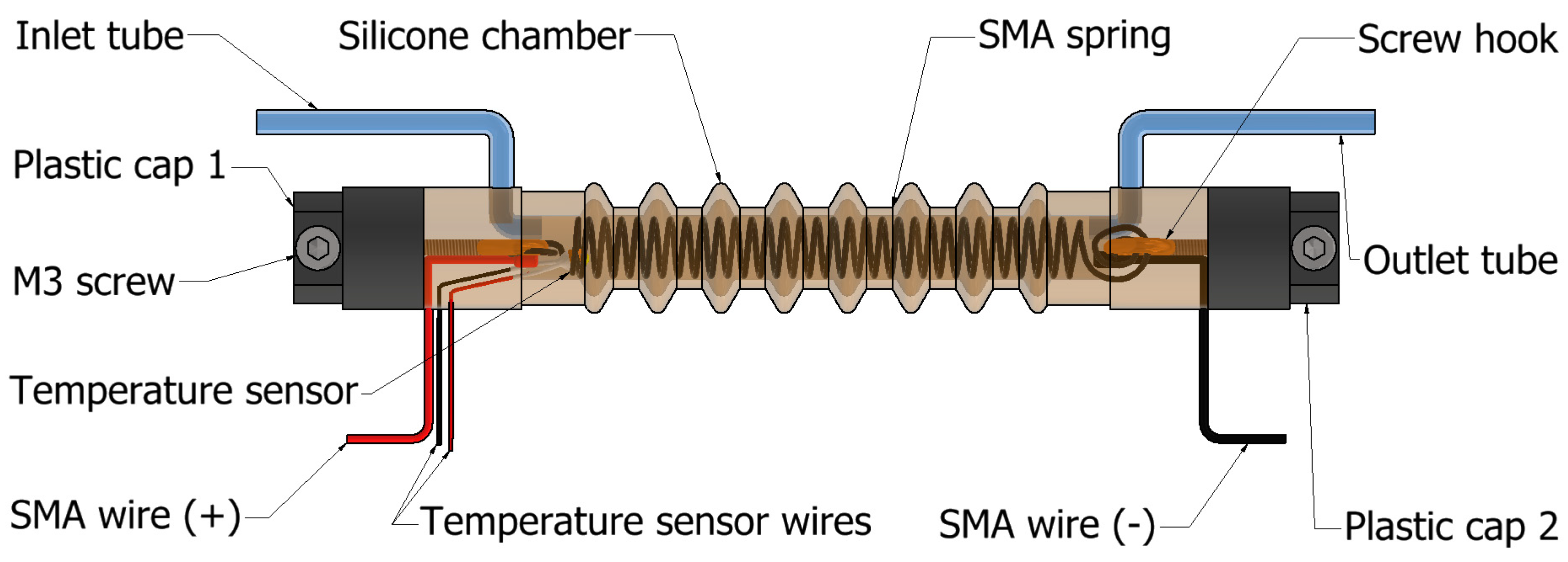
Figure 3.
(a) Front projection of the links of Finger 1; (b) section view of the robot jaw; (c) SMA coil at austenite state; (d) prototype of the gripper jaw.
Figure 3.
(a) Front projection of the links of Finger 1; (b) section view of the robot jaw; (c) SMA coil at austenite state; (d) prototype of the gripper jaw.


Figure 4.
Free body diagram of a gripper jaw.

Figure 5.
(a) Experimental setup of force measurement of single SSA; (b) schematic diagram of the experiment setup.
Figure 5.
(a) Experimental setup of force measurement of single SSA; (b) schematic diagram of the experiment setup.
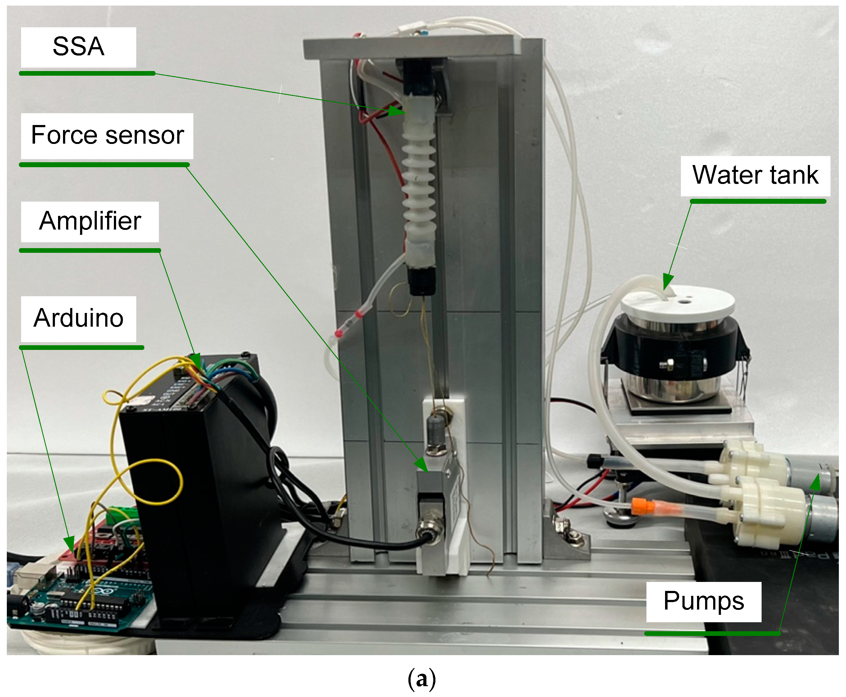

Figure 6.
The block diagram of the temperature control system with KP = 40, KI = 1, and KD = 0.
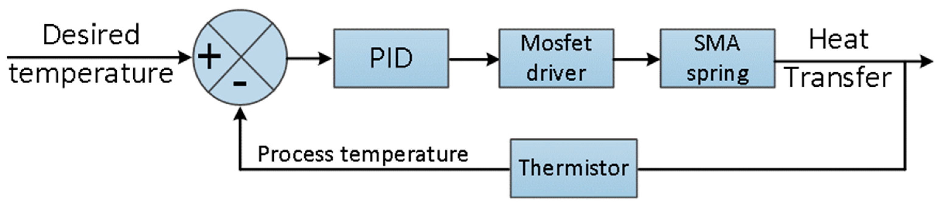
Figure 7.
The temperature decreasing time between the natural cooling and the water cooling of the SMA spring in experiments in Figure 5.
Figure 7.
The temperature decreasing time between the natural cooling and the water cooling of the SMA spring in experiments in Figure 5.
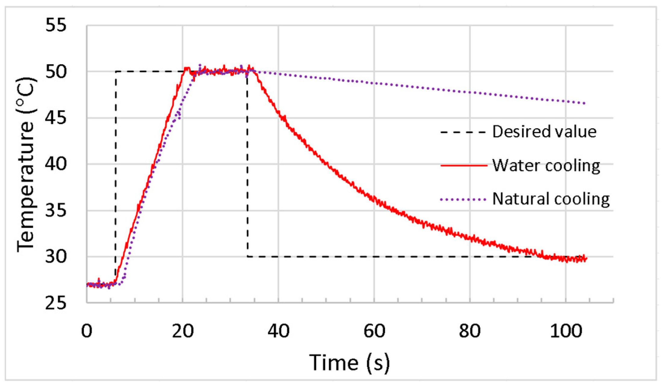
Figure 8.
The relationship between force and temperature relation.
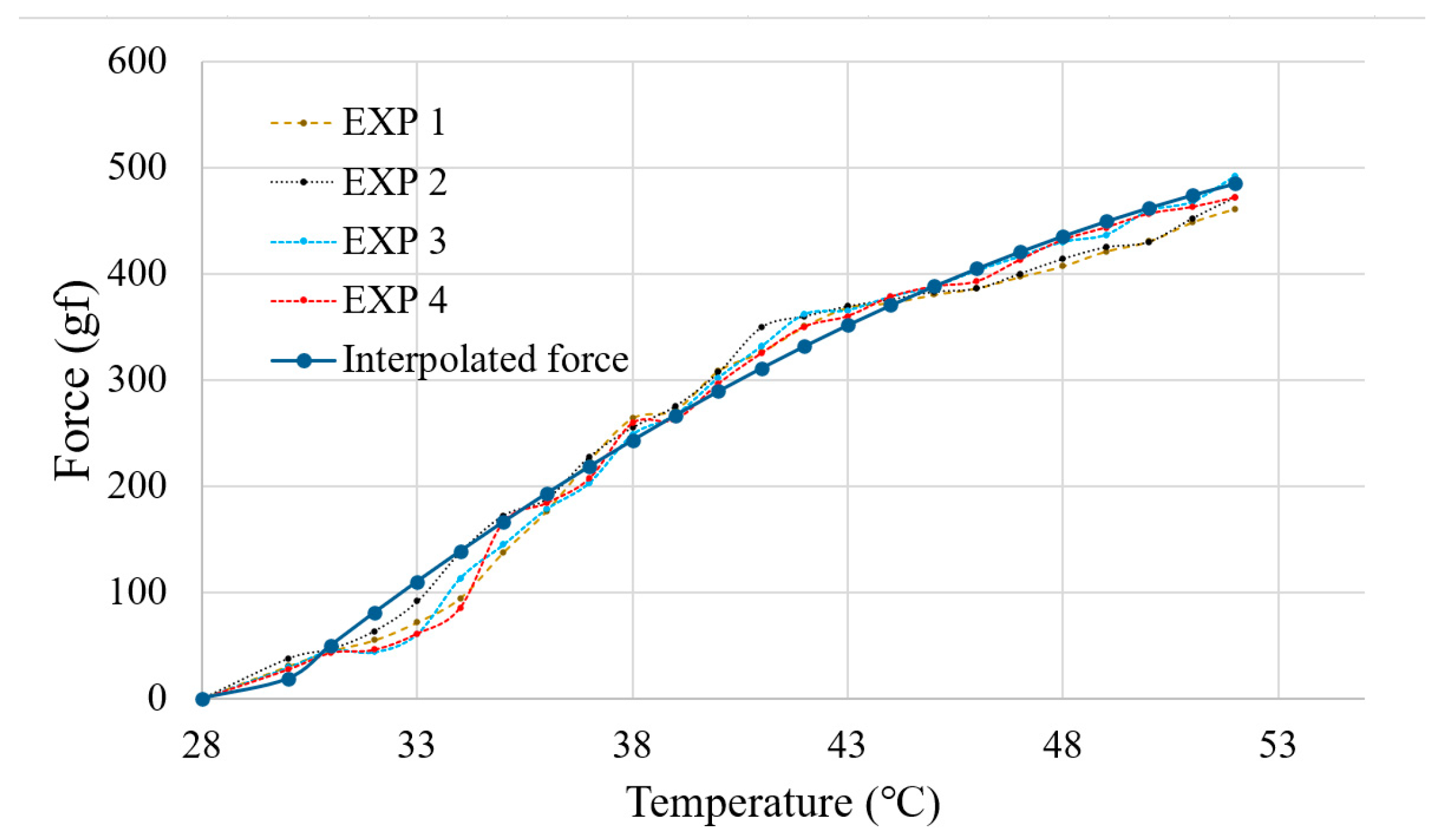
Figure 9.
(a) Experimental setup for finger force measurement; (b) experimental result of the contact force.
Figure 9.
(a) Experimental setup for finger force measurement; (b) experimental result of the contact force.


Figure 10.
The finger when applying a load onto the edge: (a) Experimental setup; (b) experimental result of the variable stiffness with the joint in martensite phase and austenite state.
Figure 10.
The finger when applying a load onto the edge: (a) Experimental setup; (b) experimental result of the variable stiffness with the joint in martensite phase and austenite state.

Figure 11.
The experiment setup for grasping tests: (a) real photo of the experiment; (b) schematic diagram of the experiment.
Figure 11.
The experiment setup for grasping tests: (a) real photo of the experiment; (b) schematic diagram of the experiment.
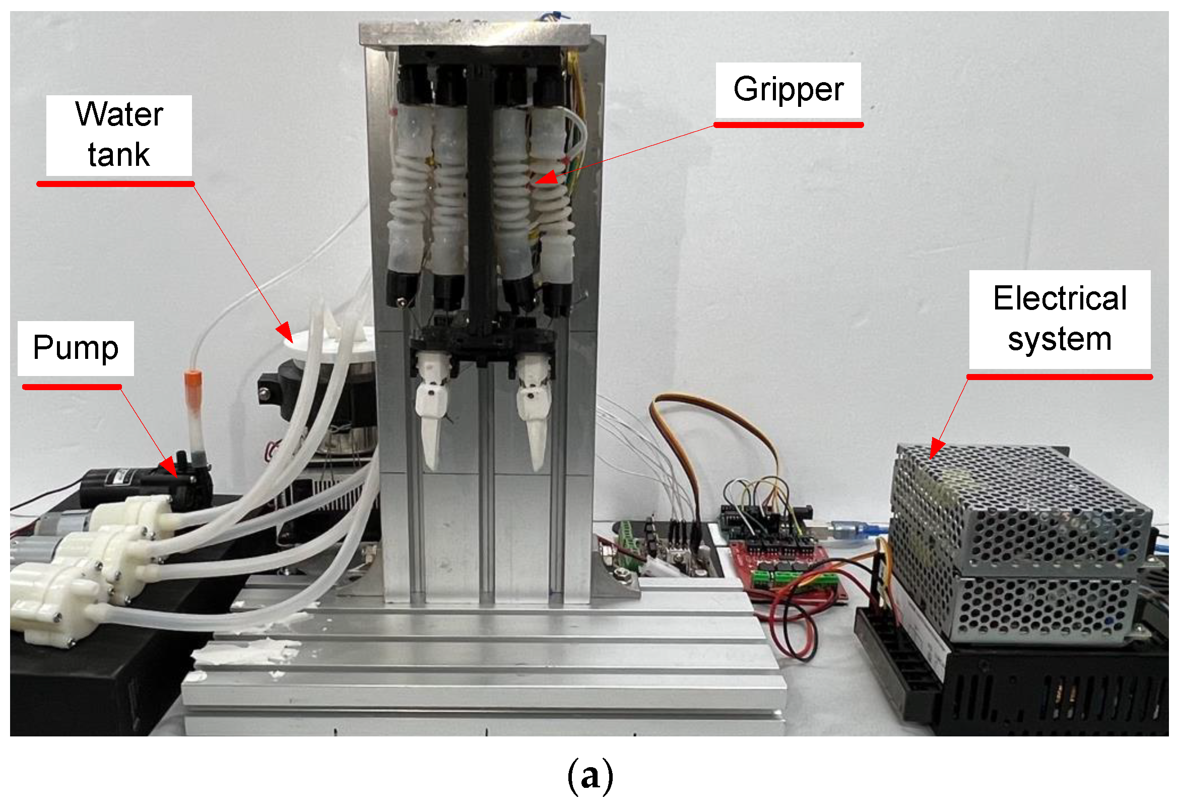

Figure 12.
Overview of the gripper grasping objects: (a) The resting state of the gripper; (b) the open state of the gripper; (c) the closed state of the gripper; (d) grasping of a scale weight 1; (e) grasping of a scale weight 2; (f) grasping of a scale weight 1; (g) grasping of a battery; (h) grasping of an egg; (i) grasping of a box.

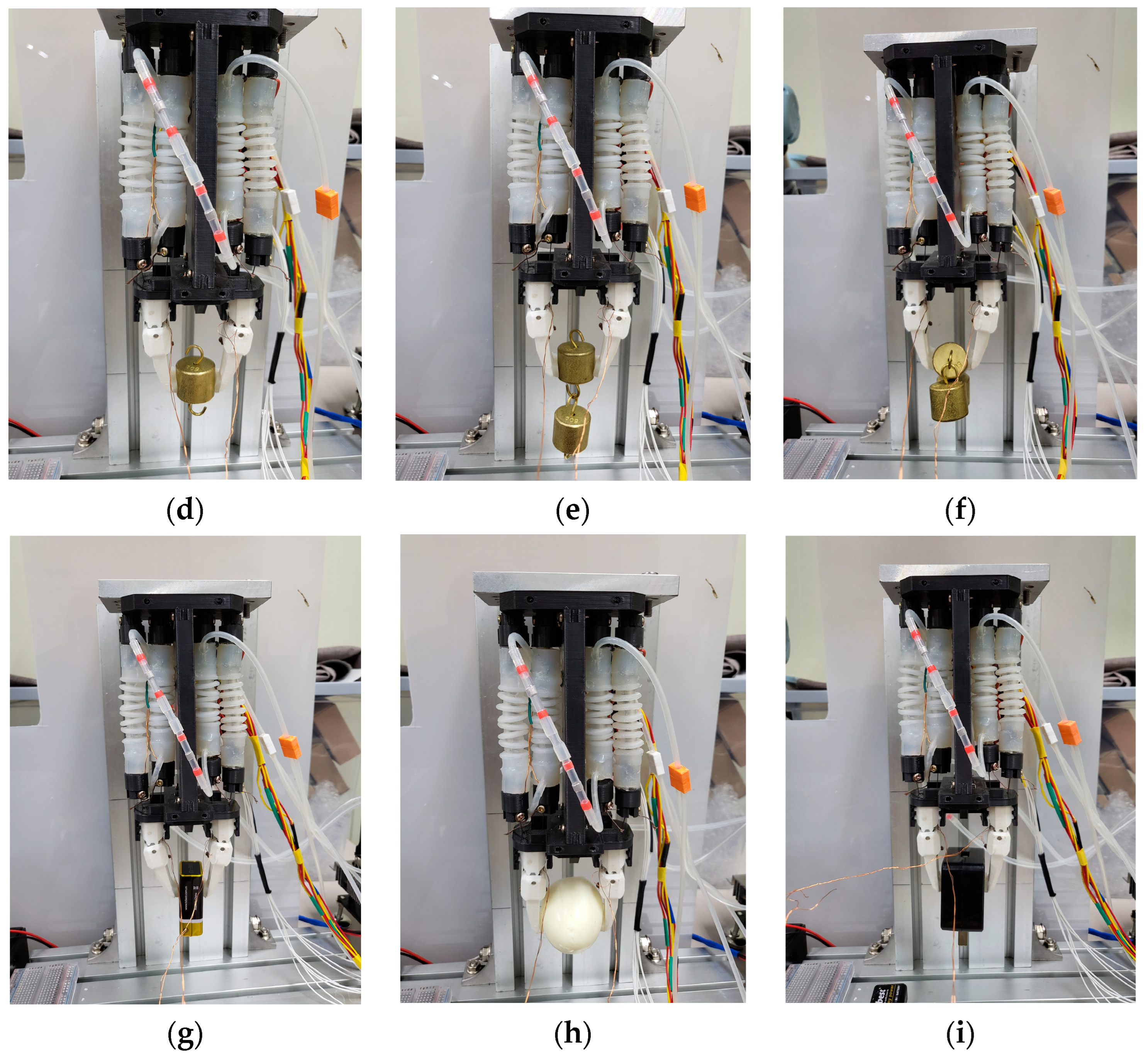
Figure 13.
Control algorithm block diagram of the gripper.

Table 1.
Parameters of the SMA spring.
| Parameter | Symbol | Value |
|---|---|---|
| Material | NiTi-45 | Nitinol |
| Spring diameter | D | 6.5 mm |
| Wire diameter | d | 0.75 mm |
| Original length | Lmin | 20 mm |
| Maximum length stretch | Lmax | 150 mm |
| Number of coils | n | 21 |
| Elastic modulus at room temperature | E | 50 GPa |
| Austenite temperature | 45–50 °C |
Table 2.
Target weights, sizes, and required temperature (T) for grasping tests. Symbol “×” indicates failed to lift.
Table 2.
Target weights, sizes, and required temperature (T) for grasping tests. Symbol “×” indicates failed to lift.
| Target | Weight [g] | Size [mm] | Temperature [°C] |
|---|---|---|---|
| A scale weight | 50 | ϕ22 × 19 | 35 |
| 2 scale weights | 100 | ϕ22 × 19 | 45 |
| 3 scale weights | 150 | ϕ22 × 19 | 55 |
| A battery | 45 | 25 × 40 × 18 | 35 |
| An egg | 45 | Null | 35 |
| A charger | 60 | 60 × 60 × 30 | 40 |
Disclaimer/Publisher’s Note: The statements, opinions and data contained in all publications are solely those of the individual author(s) and contributor(s) and not of MDPI and/or the editor(s). MDPI and/or the editor(s) disclaim responsibility for any injury to people or property resulting from any ideas, methods, instructions or products referred to in the content. |
© 2023 by the authors. Licensee MDPI, Basel, Switzerland. This article is an open access article distributed under the terms and conditions of the Creative Commons Attribution (CC BY) license (https://creativecommons.org/licenses/by/4.0/).
Share and Cite
MDPI and ACS Style
Do, P.T.; Le, Q.N.; Luong, Q.V.; Kim, H.-H.; Park, H.-M.; Kim, Y.-J. Tendon-Driven Gripper with Variable Stiffness Joint and Water-Cooled SMA Springs. Actuators 2023, 12, 160. https://doi.org/10.3390/act12040160
AMA Style
Do PT, Le QN, Luong QV, Kim H-H, Park H-M, Kim Y-J. Tendon-Driven Gripper with Variable Stiffness Joint and Water-Cooled SMA Springs. Actuators. 2023; 12(4):160. https://doi.org/10.3390/act12040160
Chicago/Turabian StyleDo, Phuoc Thien, Quang Ngoc Le, Quoc Viet Luong, Hyun-Ho Kim, Hyeong-Mo Park, and Yeong-Jin Kim. 2023. "Tendon-Driven Gripper with Variable Stiffness Joint and Water-Cooled SMA Springs" Actuators 12, no. 4: 160. https://doi.org/10.3390/act12040160
Note that from the first issue of 2016, this journal uses article numbers instead of page numbers. See further details here.