Article

Enhancing Seismic Resilience of Existing Reinforced Concrete Building Using Non-Linear Viscous Dampers: A Comparative Study

1
School of Civil and Environmental Engineering (SCEE), National University of Sciences and Technology (NUST), H-12 Sector Islamabad, Islamabad 44000, Pakistan
2
School of Engineering, Faculty of Applied Science, University of British Columbia, Okanagan, Kelowna, BC V1V 1V7, Canada
*
Authors to whom correspondence should be addressed.
Actuators 2023, 12(4), 175; https://doi.org/10.3390/act12040175
Submission received: 25 March 2023 / Revised: 11 April 2023 / Accepted: 13 April 2023 / Published: 17 April 2023

Abstract

:
After the catastrophic destruction of the October 2005 Kashmir earthquake, the first building code of Pakistan was developed in 2007. The sole purpose of the building code of Pakistan (BCP) was to incorporate advancements in earthquake-resistant design to fortify structures and ensure the safety of citizens against future seismic events. After 2007, the BCP was not revised till 2021 to include the changes over time. However, the recently updated version of BCP 2021 highlights that the seismicity of many regions in Pakistan is high, which is not truly reflected in the BCP 2007. Therefore, the advancements in earthquake-resistant design due to the growing concerns about the potential risks of seismicity in the region have been incorporated into the updated version of the BCP. However, there are concerns among researchers that many structures designed on the 2007 code may need seismic fortification. Therefore, the current study focuses on the seismic fortification of existing systems that were developed using previous codes. Non-linear viscous fluid dampers are used to improve the seismic resilience of existing structures. This study compares the seismic performance of an existing reinforced concrete building with and without non-linear viscous dampers and subjected to a non-linear dynamic analysis. The performance of the building is evaluated in terms of story displacement, story drift, story acceleration, and energy dissipation mechanisms. Adding the non-linear fluid viscous dampers in the structure caused a decrease in the inter-story drift by around 31.16% and the roof displacement was reduced by around 36.58%. In addition to that, in a controlled structure, more than 70% of energy was dissipated by the fluid viscous dampers. These results indicate that adding the non-linear fluid viscous dampers to the existing structure significantly improved the vibration performance of the system against undesirous vibrations. The outcomes of this study also provide a very detailed insight into the usage of non-linear viscous dampers for improving the seismic performance of existing buildings and can be used to develop effective strategies to mitigate the impact of seismic events on already built structures.

1. Introduction

Earthquakes are naturally occurring phenomena that have posed a long threat to human civilization. Over an extended period in human history, our understanding of earthquakes and our capacity to implement effective mitigation measures against their adverse effects have been limited. Nonetheless, in recent decades, meaningful advancements have been made in understanding seismic events and our competence to anticipate, develop strategies, and respond to them [1]. Annually, natural disasters claim the lives of approximately 60,000 individuals globally, with the majority of fatalities attributed to the collapse of buildings during earthquakes [2]. According to the World Health Organization (WHO) 2020 report, between 1998 and 2017, seismic events caused nearly 750,000 fatalities globally, accounting for 50% of all deaths stemming from natural disasters throughout that time frame. The inability of human beings to accurately measure the immense energy released by earthquakes, which occur within a brief time frame, served as the driving force for establishing and advancing seismology as a scientific discipline [3]. Seismologists are experts in understanding earthquake phenomena and the waves generated. They are crucial in understanding seismic activity and identifying the seismic hazards in relevant areas, and formulating earthquake hazard models that are used as the basis for the structural design of buildings and other infrastructures [4].
An earthquake is a sudden and rapid shaking of the Earth’s surface caused by the release of energy stored in rocks [5]. This energy is usually released due to the movement of tectonic plates, which are large pieces of the Earth’s crust that move slowly and can become stuck or locked together. When the plates suddenly move past each other, the energy that has built up is released, causing an earthquake [6]. Seismic waves arise due to the abrupt displacement or fracture of rocks along a fault plane [7]. Earthquakes are of significant concern for underdeveloped countries because of the constrained resources and substandard infrastructures [2]. The damage caused by seismic activity in such countries can range from structural failure to infrastructure damage causing refugee crises and immense death tolls.
Similarly, developing countries have limited resources to recover from the after-effects of earthquakes, causing prolonged suffering and exacerbating existing economic and social lives [8,9]. Different codes and standards have been established to promote seismic resilience in building design and construction [4,10,11,12]. The ultimate goal of these guidelines is to enhance public safety and minimize the adverse impacts of seismic activity on both life and the economy. The enforcement of codes and standards for seismic engineering is commonly achieved by applying building codes and regulations that demand strict adherence to the prescribed seismic design criteria [13]. In practice, these regulations act as legal instruments that require structural engineers and builders to follow seismic design guidelines during the design and construction of buildings and infrastructure [14]. Failure to comply with these regulations can result in legal action and potential liability for any resulting damage or loss of life. Considering the severe impact of seismic activity on buildings and infrastructure, it is imperative to focus on designing new structures to be seismic-resistant and improving the seismic resilience of existing buildings. To ensure the selection of appropriate retrofitting strategies that effectively address the seismic assessment of existing reinforced concrete (RC) buildings, conducting a preliminary assessment of their seismic inadequacy is an essential step [15]. Hence, ongoing research is being undertaken to develop advanced and economically viable strategies that can enhance the seismic performance of existing structures and minimize the potential for damage and loss of life during earthquakes [16,17,18,19,20,21].
Pakistan is in a seismically active zone, making it more vulnerable to frequent earthquakes. It exists at the boundary of both Indian and Eurasian tectonic plates [22,23,24]. The convergence and collision of these plates result in high hazards, which produce moderate to strong ground motions [25,26,27]. In the northern part of Pakistan, along the border of China and India, the geodynamic evolution of the Indus–Tsangpo suture zone gave rise to mountain ranges of the Himalayas because of the collision above [28]. Additionally, complex terrains such as landslides [29], soil liquefaction [27,28,30], tsunamis [31] and unusual geology [32,33] make this region susceptible to more seismic consequences. The area of Pakistan has suffered various devastating earthquakes in its history. In May 1935, the activity of the Chamman thrust fault resulted in a catastrophic earthquake measuring 7.7 on the magnitude scale, which caused the loss of 30,000 lives [34]. Later on, the earthquake of 2005 proved to be a wake-up call for the country to develop and improve its building codes and seismic safety measures. The 2005 earthquake highlighted the inadequacy of the existing structures to withstand seismic activity, resulting in a significant loss of life and property damage [35].
Pakistan is located in a seismically active region and is vulnerable to earthquakes. Therefore, it is crucial to conduct research to develop effective strategies for mitigating the risk of damage to buildings and the loss of life due to earthquakes. This research includes investigating the seismic behavior of existing buildings, developing retrofitting techniques, and identifying suitable locations for new structures based on their seismic safety. By implementing these strategies, the country can improve its resilience to earthquakes and minimize the impact of future seismic events.
Peak Ground Acceleration (PGA) is a seismic hazard parameter, which is considered in the building code of Pakistan (BCP) 2007. In BCP 2007, Pakistan was divided into five seismic zones (1, 2A, 2B, 3 and 4). Each seismic zone is provided with a specific value of PGA. The formula used to calculate the base shear (V) of the building is given in Equation (1)
V = C v I R T W
where I is an importance factor per BCP 2007 for each building category, Cv is the velocity-based ground response coefficient for specific seismic zones and soil profiles. R is the response modification factor for lateral force-resisting systems. T is the fundamental time. W is the weight of the building.
The BCP 2007 was revised in 2021. The updated BCP 2021 shows that the seismicity of many regions in Pakistan is very high, and that there are better choices than the division of Pakistan into seismic zone based on the PGA. Therefore, it was decided in BCP 2021 that PGA will no longer be considered a governing seismic hazard parameter for designing buildings. Instead of PGA, like all modern codes, spectral acceleration will be taken as a seismic hazard parameter. Therefore, spectral acceleration is an important parameter in seismic design in BCP 2021, in which Ss (mapped spectral acceleration of short period at 2% probability of exceedance in 50 years) and S1 (mapped spectral acceleration of long period at 2% probability of exceedance in 50 years) are given to each site. According to the BCP 2021, the formula used to calculate the base shear (V) is shown in Equation (2).
V = S D s I R W
where
S D s = 2 3 F a S s
SDs, Fa, I, R, and W are the design spectral acceleration parameter, site coefficient, occupancy importance, response modification factor, and weight of the building, respectively.
According to BCP 2007, PGA is considered for the design of buildings. While in BCP 2021, the spectral acceleration value for each site is considered for the design of buildings. Plotting the response spectrum of both building codes for Islamabad, as shown in Figure 1, it can be seen that Islamabad’s seismicity is comparatively higher in BCP 2021 compared to BCP 2007. The parameters used to plot the response spectrum of building codes are given in Table 1.

Research Significance

The existing buildings in Pakistan are designed on spectral acceleration values, which are lesser than the original values, according to BCP 2021. Therefore, these buildings are vulnerable to major seismic events. If these buildings are not properly seismically fortified, then in the case of any major strong earthquake event, the damages would be worse than the recent Turkey–Syria 2023 earthquake. Therefore, buildings in Pakistan are required to undergo fortification to reduce the effects of seismic activity. To highlight the importance of retrofitting existing buildings, a case study building is analyzed linearly according to both codes, i.e., BCP 2021 and BCP 2007.
The study of the practical applications of non-linear viscous damper for retrofitting is rarely available in the literature. This research aims to thoroughly understand the effect of adding non-linear viscous dampers to an already-designed building. The building is modeled and analyzed using a non-linear time-history analysis on three different earthquakes in Perform 3D. The responses regarding inter-story drift, roof displacement, acceleration, and kinetic energy dissipation are analyzed. The paper investigates the application of non-linear viscous dampers on existing structures and evaluates their advantages from the technical perspective, indicating the effectiveness of the proposed straightforward approach to retrofitting existing buildings in Pakistan to enhance their seismic performance.

2. Case Study Building

This study considers a hospital building located in Islamabad, Pakistan, designed on the BCP 2007 response spectrum. There are seven types of columns and four types of beams on each building floor. Figure 2 shows a floor plan and a finite 3D element model. In Figure 2 the red part indicates RC walls. The salient features of the building are shown in Table 2.
When the building is analyzed using the response spectrum of both building codes, i.e., BCP 2007 and BCP 2021, the responses of the structure significantly increased according to BCP 2021 compared to BCP 2007, as shown in Figure 3. The structure’s displacement and inter-story drift responses increased by 21.84% and 22.09%, respectively. While the shear force and overturning moments of the structural systems are greater than 24.27% and 21.98%, respectively. Therefore, the building designed on BCP 2007 required retrofitting and seismic fortification.

3. Seismic Fortification of Existing Buildings

Contemporary building codes and standards typically incorporate seismic design considerations, yielding new buildings that are designed to withstand seismic forces. Most buildings today were constructed before modern seismic codes and provisions were developed. Even those buildings that were built after the development of building codes for Pakistan may need some fortification of the existing structures because of the increased seismic demands of structures generated through new seismic activity [36]. As our understanding of seismic activity increases, building codes regularly evolve to incorporate more robust seismic design requirements [37]. This means that if a building was constructed following the building code at that time, it might not meet the current seismic demands; hence, the seismic fortification of buildings enhances the seismic performance of existing structures, thereby increasing their capacity to withstand seismic demands [38]. Technically, the seismic retrofitting of buildings can be broadly classified into two categorical techniques [39]. The first technique is the “member-level technique,” which aims to improve the seismic performance of structural members. The most deficient structure member is targeted, and its capacity is increased [40]. The “Structural-level technique” deals with a building as a whole and tends to increase the ability of the building to seismic effects by the addition of new structural or substructural elements, such as braces [41,42,43], frames, and dampers [44,45,46,47].
Comparing the effectiveness of structural-level techniques with member-level techniques for seismic retrofitting is subject to specific conditions of the building and the seismic hazards that it faces. Structural-level techniques may provide a more comprehensive and efficient solution for enhancing the seismic performance of existing buildings. This is because structural-level techniques treat the building as a unified system instead of addressing individual members. By adding new structural elements such as bracings and shear walls, structural-level techniques can improve the overall stiffness and strength of the building. In earthquake-prone areas such as Pakistan, where older buildings exist without modern building codes, a structural-level retrofitting approach may be appropriate to improve the seismic performance of the existing buildings. Some feasible retrofitting techniques that could be used for the seismic fortification of buildings in Pakistan are discussed below.

3.1. Lateral Bracing System

Lateral bracing can be critical in terms of the design of beam and columns that helps to maintain the structural integrity of a building during seismic events. Beams and columns are often subjected to lateral forces during seismic events, which can cause them to buckle or twist [48]. Lateral bracing prevents this from happening by providing additional support and stiffness. According to the research findings, the seismic behavior of a building is significantly impacted by the position and orientation of the lateral force-resisting systems [48]. The appropriate type of lateral bracing system for a building depends on several factors, such as the design, location, and height. Selecting the right lateral bracing system is critical to ensure that the installation can resist seismic forces and remain safe during an earthquake. Therefore, different types of lateral bracing systems may be used in other buildings based on the specific requirements of the building [49,50].

3.2. Seismic Retrofit Jacketing

Seismic retrofit jacketing, or “seismic column jacketing”, is a technique to improve the seismic performance of a building’s columns or piers. Seismic retrofit jacketing uses a steel or composite jacket around a building’s column or pier to enhance its strength and ductility and improve its ability to resist seismic forces during an earthquake. This process involves the installation of a reinforcement layer to the existing structure, helping to prevent the column or pier from buckling or failing [51]. There exist different types of jacketing techniques [52,53,54,55].
Seismic retrofit jacketing effectively strengthens building columns and enhances their ability to withstand seismic forces during an earthquake. However, it is important to note that this technique can be disturbing as it involves reinforcing the columns, which may require the demolition and rebuilding of portions of masonry infills and plaster. This can result in high costs and downtime for the building. Another area for improvement with seismic retrofit jacketing is the complexity of the design process. Identifying the columns that need retrofitting, as well as the choice of the battens area and spacing, requires a significant number of attempts and iterations, especially when dealing with irregular building configurations. Non-linear static analysis, such as the pushover method, can help assess the building’s performance before and after retrofitting, but it can be time-consuming and it requires extensive expertise [53].

3.3. Dampers

In seismic retrofitting, dampers are mechanical devices utilized to reduce seismic waves’ effects by absorbing or dissipating energy [54]. The primary purpose of dampers is to decrease the movement and vibration of a building during an earthquake by converting the kinetic energy of the seismic waves into thermal energy. Various dampers exist for the seismic retrofitting of structures [56,57,58,59,60,61].
The selection of a suitable damper for seismic retrofitting is influenced by various factors, such as the structural system of the building, the anticipated level of seismic activity, and the desired level of retrofitting. It is crucial to note that dampers are not the only technique available for seismic retrofitting, and each method must be evaluated critically before deciding on the most appropriate damper for a specific building [56,62,63].
Fluid viscous dampers (FVDs) are often preferred over other mentioned seismic retrofitting techniques because they provide a stable and reliable performance over various seismic events. They effectively reduce the movement and vibration of a building during an earthquake by absorbing the energy of seismic waves through a fluid. Additionally, fluid viscous dampers are relatively easy to install, they require minimal maintenance, and they have a long service life. They can be easily integrated into the existing structural system of a building and they do not significantly alter the building’s appearance or function, hence they are the preferred technique.
Among the different types of fluid viscous dampers, non-linear viscous dampers (velocity coefficient less than one) are preferred because of the limiting peak value of damper forces at large damper velocities [64,65], while in the case of a linear damper, the damping force increases with the damper velocity. Non-linear viscous dampers have a variable damping force that can be tuned to match the specific vibration characteristics of a structure. This allows for more precise and effective vibration control, which can result in better overall performance and safety [66,67]. The findings of different researchers also indicate that non-linear viscous dampers are much more beneficial than conventional linear viscous dampers. Kaleybar et al. investigated the seismic behavior of moment frames at eleven ground motions concluding that structures with the same damping coefficient decreased the seismic response and increased energy dissipation when they were retrofitted with non-linear viscous dampers rather than linear viscous dampers [68]. A similar decrease in the response of structure was observed by Mevada et al. [64] with the increase in the non-linearity of dampers. Additionally, non-linear FVDs that were added to the structure reduced damages at design-based and maximum-considered earthquakes. Additionally, non-linear viscous dampers have a simpler design and are easier to install than other types of dampers, such as tuned mass dampers. This makes them a more practical solution for many applications. Therefore, the current research includes the addition of a non-linear viscous damper in an RC structure to increase its seismic capacity.

3.3.1. Fluid Viscous Damper

Originally, fluid viscous dampers found their application in the military and aerospace sectors. Initially, the military and aerospace industries were the first to employ fluid viscous dampers. Later, these dampers were adapted for structural engineering during the late 1980s and early 1990s [69]. These FVDs operated in a passive mode, because these type of FVDs refers to devices that are designed to function without any external power sources and possess properties that remain stable during the seismic response of the structure [54]. As seismic input energy is concentrated within a relatively narrow frequency range, passive systems are effective, sturdy, and cost-efficient solutions.
The energy dissipation in FVD devices arises from the relative velocities that emerge between their connection points. Typically, the force–displacement reaction of these dampers is contingent on the motion frequency. Moreover, the forces that originate from these devices in the structure tend to be out of sync with the internal forces that are produced by shaking. This results in the maximum forces that are generated by the dampers not coinciding with the peak internal forces that correspond to the transient deformations of the structure [70].

Components of Fluid Viscous Dampers

The FVD device consists of a high-resistance cylinder containing silicone fluid and a piston with small holes on one of its heads. During a seismic event, the piston slides inside the cylinder, transferring fluid from one chamber to another and generating damping force. The displacement of the piston converts kinetic energy into heat through thermal expansion and contraction of the fluid. Figure 4 shows a typical FVD diagram.
A typical viscous fluid damper produces a resistive force determined by its output. The power generated by the damper is a result of the differential pressure across the piston head, which is responsible for the input motion. This resistive force, commonly referred to as the damping force, is directly related to the changes in fluid volume that occur due to the product of the piston’s travel and piston area as it moves. Since the fluid in the damper is predominantly compressible, the creation of the restoring force is similar to that of a spring, which occurs after the change in pressure. Linear fluid viscous dampers differ from non-linear ones in terms of the relationship between the piston’s velocity and the resistance force produced by the damper. In a linear damper, the resistance force increases proportionally as the piston’s velocity increases since the force is directly proportional to the piston’s speed.
In contrast, a non-linear damper produces a resistance force that is dependent on other variables, such as displacement or acceleration. Although linear and non-linear viscous dampers use fluids with similar properties, their intended use can vary. In linear dampers, fluid viscosity is the primary variable affecting the damping force. On the other hand, non-linear dampers use non-Newtonian fluids with viscosities that change with shear rate or stress to produce non-linear damping performance [67,71].

Characteristics of Fluid Viscous Dampers

Fluid viscous dampers (FVDs) are designed to provide a resistance force (F) that helps absorb seismic waves’ energy during an earthquake. This resistance force is determined by various factors, such as the velocity of movement, fluid viscosity, and the size of the piston’s orifices.
The equation that determines the value of P, which is related to the resistance force (F) in fluid viscous dampers (FVDs), is given by the following relationship [72]:
P = C d   *   U d   *   α   * s i n u d   *   t
Cd is the damping constant, Ud is the velocity between two ends of the damper, α is an exponent that depends on the fluid’s viscosity properties and the piston’s viscosity, and t is time—the seismic energy during an earthquake. The exponent ‘α ’ in the equation determines the P value in fluid viscous dampers (FVDs), which can be equal to or less than one. An exponent of α = 1 characterizes a linear viscous damper, whereas a non-linear FVD has an exponent of α < 1, which effectively reduces high-velocity shocks. Conversely, dampers with an exponent of α > 1 are not commonly observed in practical applications. It is important to carefully evaluate the appropriate type of FVD for a specific structure based on its behavior and desired performance [73]. Figure 5a,b show the force–velocity and displacement plots for a linear and non-linear viscous damper. As observed in Figure 5b, a non-linear viscous dashpot can dissipate more energy than a linear viscous damper when oscillated to the same level of displacement and with the same peak force (represented by the area enclosed within the force–displacement curve).

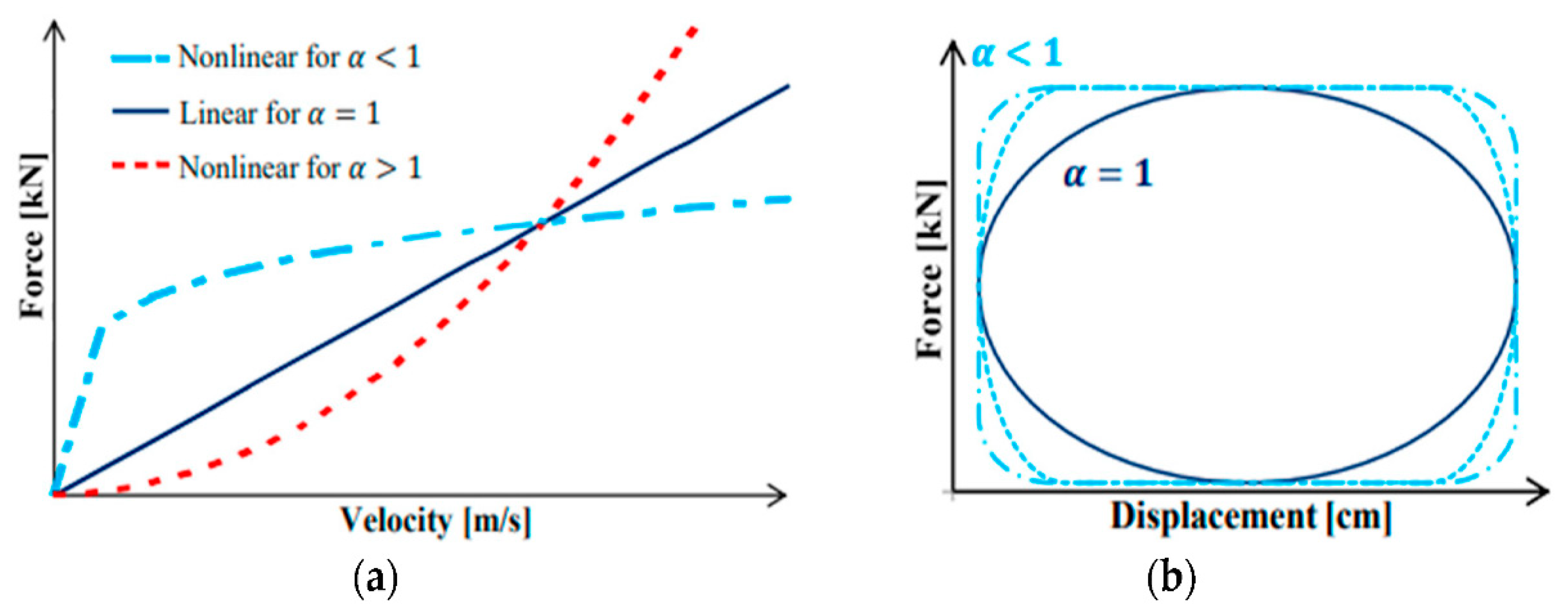
Design of Non-Linear Fluid Viscous Dampers

Various researchers have conducted experimental work to study the behavior of non-linear viscous dampers [67,75]. In all these experimental studies, the behavior of non-linear fluid viscous dampers has been studied. Our research includes utilizing the same experimented behavior to model the practical effects of using non-linear fluid viscous dampers to retrofit existing buildings. Various researchers have proposed design methodologies for using modeling non-linear FVDs in multistory buildings [64,65,76]. However, FEMA 274 provides comprehensive guidelines and design procedures for designing FVDs. FEMA 274 [77] offers design equations for non-linear fluid viscous damping devices. In a system with multiple degrees of freedom (MDOF), it is crucial to note that the effective damping ratio of the structural design as a whole is determined by Equation (4)
ξ e f f = ξ 0 + ξ d
whereas ξ0 represents the natural damping ratio of a system in the absence of dampers, ξd represents the damping ratio introduced by the mufflers. In the case of reinforced concrete structures, the inherent damping ratio is typically assumed to be 5%, whereas the dense damping ratio for non-linear viscous dampers is selected based on the desired level of damping. Once a value of the damping ratio ξd is determined, an estimate for the damping coefficient C of non-linear devices in a diagonal arrangement can be calculated by the following Equation (5), given by FEMA 274.
ξ d = Σ j λ C j φ r j 1 + a cos 1 + a θ j 2 π A 1 α w 2 a m i φ i 2
where ξd is the damping ratio of a system that is equivalent to the damping contributed by non-linear dampers, A is the parameter of velocity, Cj = damping coefficient of damper j, mi = mass of floor I, θj = inclination angle of damper j, Φi = mode displacement at the floor I, Φrj = relative horizontal displacement of damper j, A = amplitude, w = angular frequency, and α = damping coefficient.
FEMA 274 also provides a tabulated list of values for λ, which is the parameter that depends on the velocity exponent.

4. Non-Linear Modeling of Case Study’s Building

For a non-linear time-history analysis of the case building, Perform 3D is used. Two models were created, one without viscous dampers and the other with viscous dampers, as shown in Figure 6. Under the Inelastic 1D material tab in Perform 3D, the inelastic properties are assigned to the concrete for non-linear analysis. The inelastic 1D material defines the non-linear behavior of the RC concrete. The “YULRX” model accounts for strength loss and cyclic degradation implicitly. The “YULRX” model accounts for the non-linear response of the material in terms of the stress–strain history. The trilinear stress–strain response can be modeled using the YULRX model that incurs no strength loss. Perform 3D does not consider the weakening of the YULRX envelope caused by cyclic loading. Therefore, the YULRX envelope used for monotonic loading may differ from that used for cyclic loading, either by being more assertive or exhibiting strength loss at a higher deformation demand. Concrete’s compressive strength is set to 1.3 times the power specified by the designer (CTBUH 2008). Mander’s stress–strain model, which is approximated by a trilinear envelope, describes the non-linear behavior of concrete, and the tensile strength of concrete is set to be 0.33 MPa. In a compression, the hysteretic model has developed in such a way that the unloading stiffness is equal to the initial elastic stiffness and is adjusted so that the stiffness is degraded by the increase in plastic strain [78]. A bilinear hysteretic model, including strain hardening, defines steel in Perform 3D. The yield strength of steel bars is assumed to be 1.17 times the nominal yield strength (CTBUH 2008). Each column of the building is modeled using a lumped fiber modeling approach, and each fiber is assigned properties of concrete and steel. For beams, a plastic hinge modeling approach is used. A moment rotation hinge of zero length was added at the end of the shaft. To simulate the combined axial–flexural behavior, each structural wall was divided into many vertical non-linear concrete and steel fibers. For the modeling of shear walls, the fiber modeling approach is made, and the P-M3 fiber interaction is used to simulate the effect of axial and flexural loading, respectively, Elastic thin shell elements were used to model the slab.
For modeling non-linear fluid viscous dampers (FVDs) using Perform 3D, the FVDs were modeled using a Maxwell model consisting of a spring element and a dashpot damper connected in series. The spring element represents the overall stiffness of the brace element, its connections (such as clevises), and the internal stiffness of the non-linear FVD. This model allows for a more accurate representation of the behavior of the non-linear FVD under different loading conditions. The degree to which a non-linear FVD impacts a system is greatly affected by its axial stiffness (the damper’s internal mechanism to resist elongation and deformation along its lengthwise axis). The mechanical behavior of the damper–brace system is affected by various factors, including the axial stiffness of the non-linear FVD [79]. The effectiveness of a non-linear FVD is determined by the ratio of the FVD force to the damper’s axial stiffness. Axial stiffness affects the mechanical behavior of the damper brace system. Velocity coefficient, axial stiffness of damper proportion, and equivalent axial stiffness of the entire system affect the non-linear viscous dampers. The natural frequency of the whole system is affected by the axial stiffness of the non-linear viscous dampers. A greater axial stiffness value means a higher natural frequency value. This means that dampers will be more effective at reducing the amplitude of the vibrations at higher frequencies. While the stiffness values of bracing elements and connections can be easily calculated, the axial stiffness of non-linear FVDs is private information that is specific to the manufacturer and design properties [80].
To overcome this challenge, the study utilized an axial stiffness value of 150 kN/mm for all non-linear FVDs in each of the four frames based on recommendations from previous research [80,81]. The main characteristic of non-linear FVDs is represented by the dashpot element in the Maxwell model. To define an FVD, two input values are required, namely the “damping coefficient” and the “velocity power”. The damping coefficient and velocity power vary depending on the performance criterion of the buildings and are designed accordingly for each story and building. For this study, the value of the velocity power is 0.5 and the coefficient of the damper is 875 KN s/m.

Dampers Location

The damper’s location is critical to achieving effective seismic protection. The placement of dampers should be carefully considered during the design phase of the building, as the location can affect their effectiveness in reducing the building’s response to seismic activity. Determining the optimal location of viscous dampers (non-linear/linear) in a building requires an iterative process in which the designer must experiment with various arrangements and locations, considering the building’s architectural design and intended use. This research followed the guidelines outlined in ASCE 7–10 for the placement of dampers. These recommendations include using at least two dampers in the direction that requires reinforcement, placing dampers on all story levels of the building, and striving for symmetry to avoid torsion. Pineda et al. in their research assessed the addition of non-linear viscous dampers in RC hospital buildings in Columbia through a non-linear dynamic analysis [82]. In this study, the optimal location of dampers was selected based on ASCE 7–10 provisions. Initially, dampers were placed in all stories in the center of the bay of the building in both directions. No significant reduction in the response of structures were noted. Then, dampers were placed at the ends of buildings to resist torsion and minimize the response, as shown in Figure 6c,d.

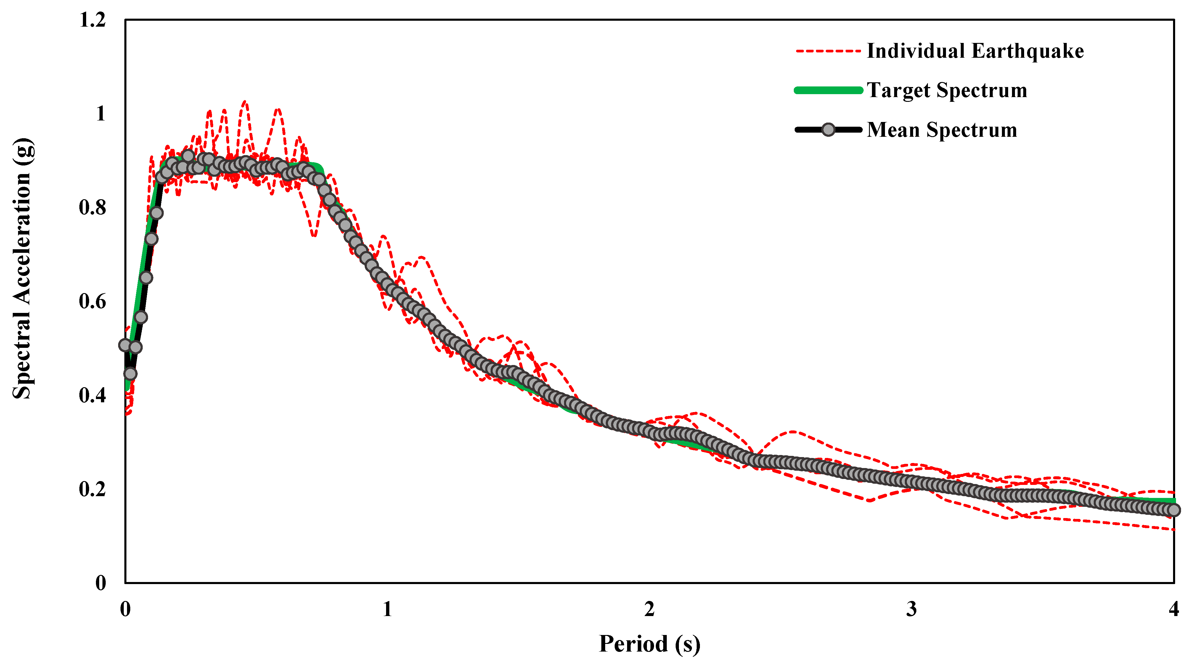
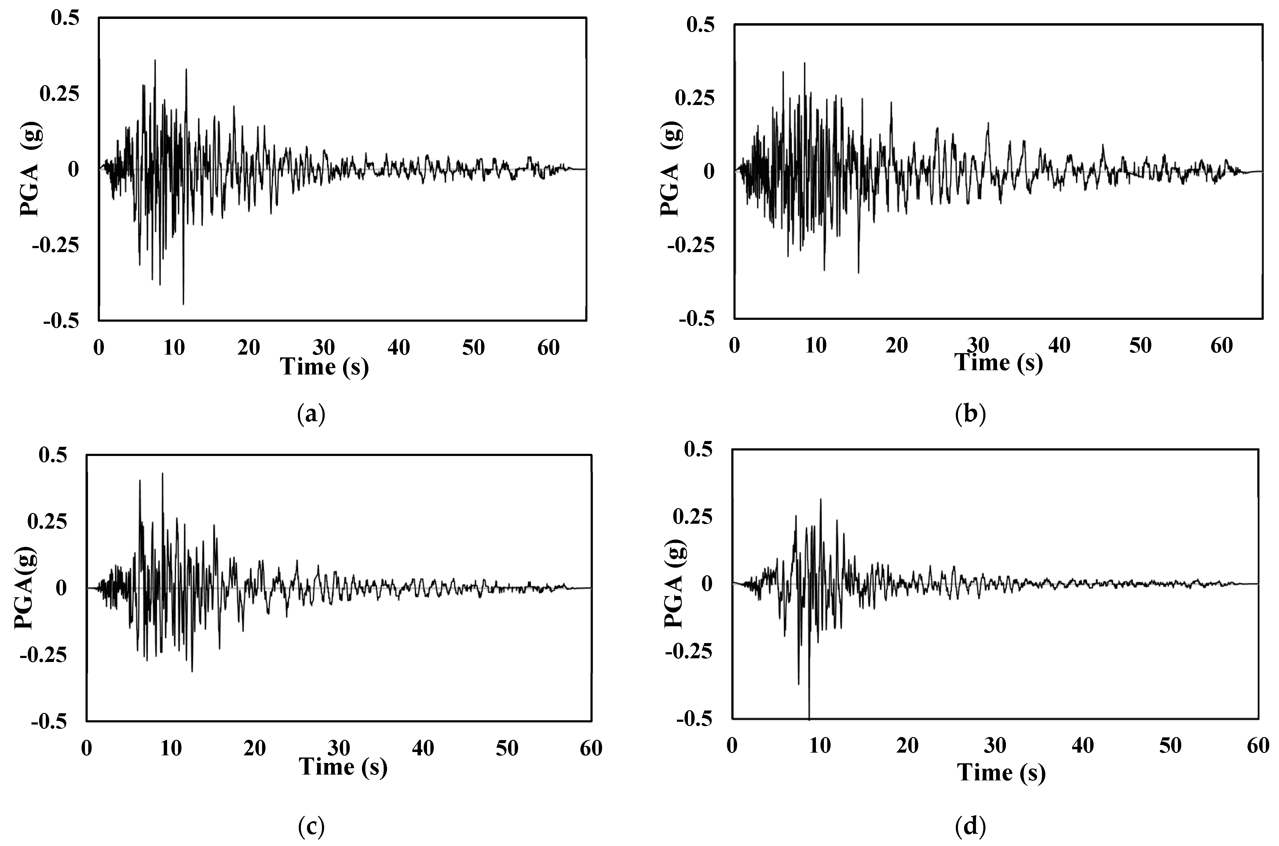
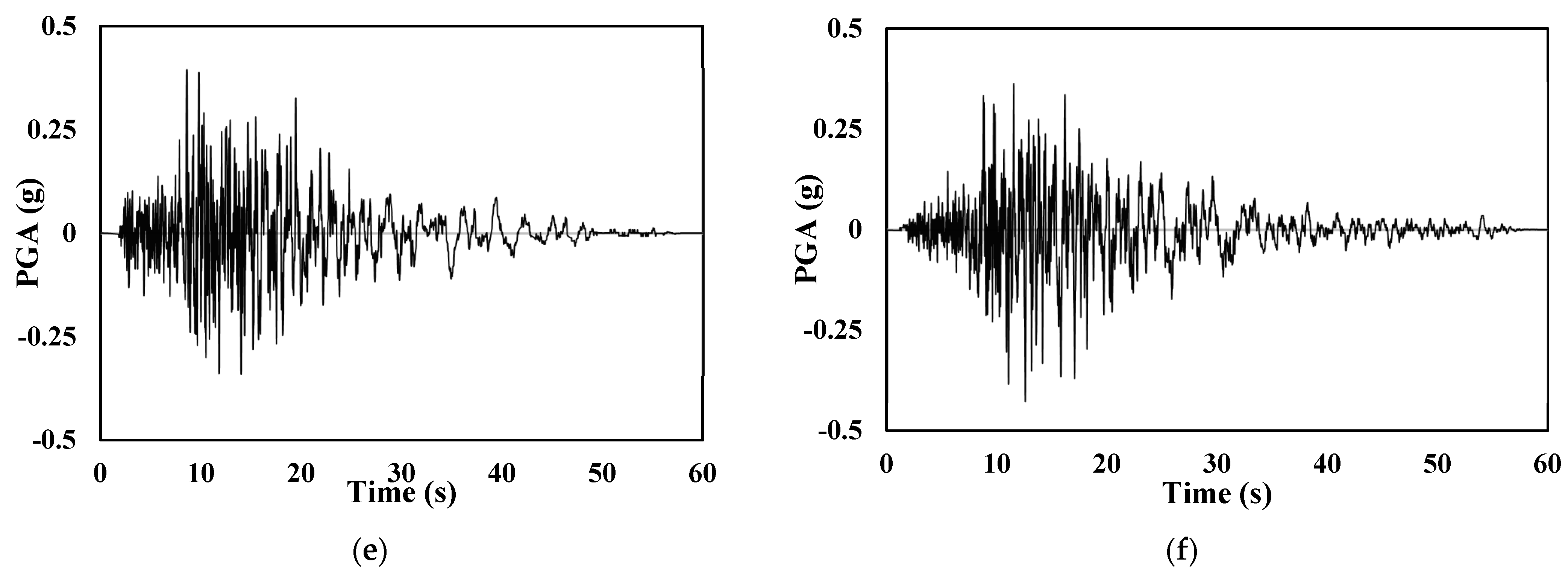
5. Selection of Ground Motions

Regarding incremental dynamic analysis, ground motion is referred to as the motion of the ground caused by an earthquake. It is a signalized function of acceleration that varies with time. The input acceleration time history applied to the structure under analysis is described by the ground motion records, and they are critical to the structure’s response to excitation [83]. Uncertainties that are related to the ground motion records chosen for the non-linear response analysis of structures can have an impact on the precision and dependability of the analysis results. There are several reasons for these uncertainties, including the limited quantity and high quality of ground motion records, the modeling presumptions and simplifications, and the ground motion’s inherent randomness and variability. Different researchers have tried to propose different selections of ground motions. Bazzurro et al., 1994, suggested that a set of seven ground motions are sufficient to cover the uncertainty associated with earthquakes for a structural reliability analysis [83]. This set of ground motions, commonly referred to as the “7-DOF” set, consists of seven records selected to represent the variability and diversity of the seismic hazard. Lin et al., 2013 [84] introduced a novel ground motion selection scheme called adaptive incremental dynamic analysis (AIDA) that adaptively changes the ground motion suites at different ground motion intensity levels to match hazard-consistent properties for structural response assessment.
These ground motions are selected from PEER database. The input parameter for the selection of the ground motion is specified in [85]. The parameters for the selection of ground motion are magnitude (6.3–7.8), Rrup values 10–50 km, fault type (strip slip and reverse), and Vs30 (480–620). Using seism match software, the selected ground motion was scaled and matched with the response spectrum of the site (Ss = 1.302 g, S1 = 0.381 g, and site class D). Table 3 illustrates the time histories, their recording station, magnitude, source-to-site distance, and Vs30 (shear wave velocity). Figure 7 shows the 5% damped response spectra of histories, site spectrum, and mean match spectrum. Figure 8 shows three ground motions and six-time histories that are used in this study.

6. Results and Discussions

A modal analysis was used to determine the structures’ natural frequency, mode shape, and damping ratio, which are the inherent dynamic characteristics of the buildings. The time period of mode 1 is 1.34 (s) for a building without a viscous damper and 0.83 (s) for a building with fluid viscous dampers. Adding a non-linear fluid viscous damper reduced the time period and increased the stiffness of the structures. In addition, the presence of a damper increases the overall damping of the structure, and the addition of dampers has little effect on the modal participation factors, as shown in Table 4. Figure 9a,d shows the modal shape of the structure, which is the translation mode in the X direction of the building, with and without viscous dampers, respectively. Similarly, Figure 9b,e illustrates the modal shape of mode 2, which is translation mode in the Y direction of the building, with and without viscous dampers, respectively. Figure 9c,f shows the rotation mode of the building, with and without viscous dampers, respectively

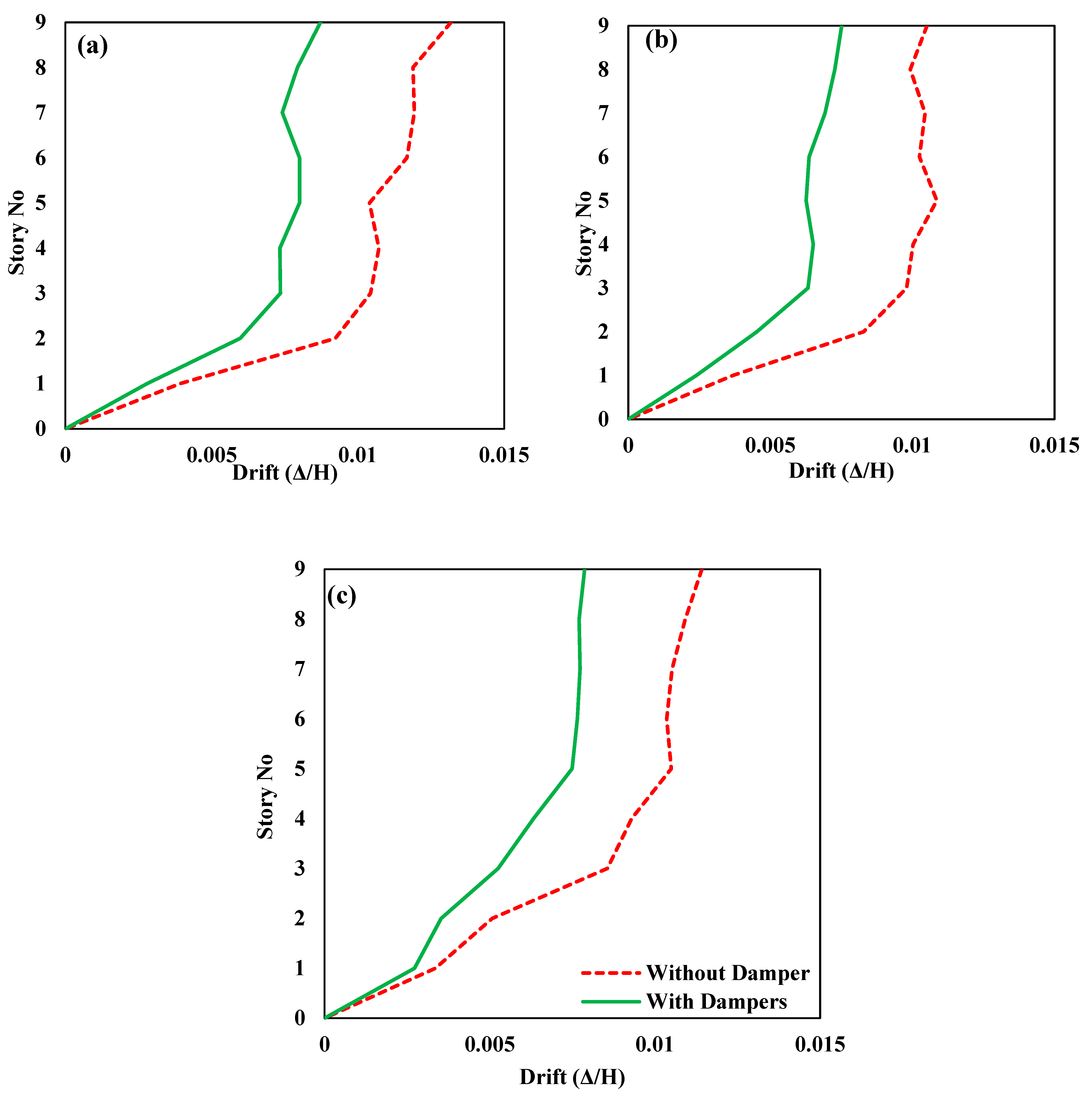
6.1. Displacement and Drift Responses

Figure 10a–c depicts the displacement responses of structure with and without FVDs when subjected to Coalinga-01 (Parkfield–Cholame 2E), Coalinga-01 (Parkfield–Stone Corral 2E), and Northridge-01 (Palmdale–Hwy 14 and Palmdale) seismic loadings, respectively. All the floor displacement of the structure equipped with FVDs (controlled structure) has been significantly reduced compared to the structure without dampers (uncontrolled structure) in each seismic loading. The FVDs increased the overall damping of the controlled structure; therefore, the displacement at each floor decreased. The fluid inside FVDs dissipated the unwanted vibrations of the host structure during the excitation event through thermal expansion and contraction of the fluid. In addition to that, FVDs also increase the stiffness of the structure, which reduces responses along the height of the building. Suppose the response improvement is quantified into percentages. In that case, the maximum decrease in the floors/story displacement can be found in the case of the Coalinga-01 (1983) earthquake measuring station Parkfield–Stone Corral 2E, which gives the maximum reduction in the response of the structure, as shown in Figure 10b. In general, the addition of a fluid viscous damper in the structure reduces the relative floor displacement, which varies in the range of 28% in the first story to 46.95% on top of the structure.
Figure 11a–c depicts the inter-story responses of controlled and uncontrolled structures when subjected to Coalinga-01 (Parkfield–Cholame 2E), Coalinga-01 (Parkfield–Stone Corral 2E), and Northridge-01 (Palmdale–Hwy 14 and Palmdale) seismic loadings, respectively. In all the earthquake loading cases, the inter-story drift curves show that FVDs significantly reduced the drift response of the structure. Carefully analyzing the drift curves shows that structures with FVDs are more likely slightly straight vertical lines, which means that the difference in the drift values of the stories is much smaller.

6.2. Acceleration Responses

The relative acceleration responses of a structure equipped with and without FVDs against the seismic forces of Coalinga-01 (Parkfield–Cholame 2E), Coalinga-01 (Parkfield–Stone Corral 2E), and Northridge-01 (Palmdale–Hwy 14 and Palmdale) are shown in Figure 12a–c, respectively. The FVDs improved the acceleration responses of the top floors of the structure in all three loading cases. However, the relative acceleration response improvement is insignificant compared to the displacement and inter-story drift response improvement with FVDs. The relative acceleration response of the structure is dependent upon the mass and the stiffness of the structure; hence, the displacement demand of the structure decreases because of the damping effect. The addition of non-linear viscous dampers increases the stiffness of the structure, because of which acceleration remains the same. Ras et al. modeled the addition of the viscous damper to the moment-resisting frame and analyzed it for a time-history analysis in SAP2000. The experimentation findings included no significant changes in the acceleration demand of viscous fluid dampers [73]. While the relative acceleration response of the uncontrolled structure and structure with FVDs almost remains the same at the bottom floors/stories.

6.3. Time Histories Responses

For the response analysis, in terms of acceleration and displacement time, histories of the top story of the structure are shown in Figure 13 and Figure 14, respectively, for all three seismic loadings. The addition of FVDs in the structure significantly improved its performance of the structure. The acceleration time-history responses (Figure 13) indicate that FVDs reduced the acceleration at the top story in all three loading cases. The displacement time-history responses have been greater reduced in the structure with FVDs at the full story under Coalinga−01 (Parkfield−Cholame 2E), Coalinga−01 (Parkfield−Stone−Corral 2E), and Northridge−01 (Palmdale−Hwy14 and Palmdale) as shown in Figure 14a–c, respectively.

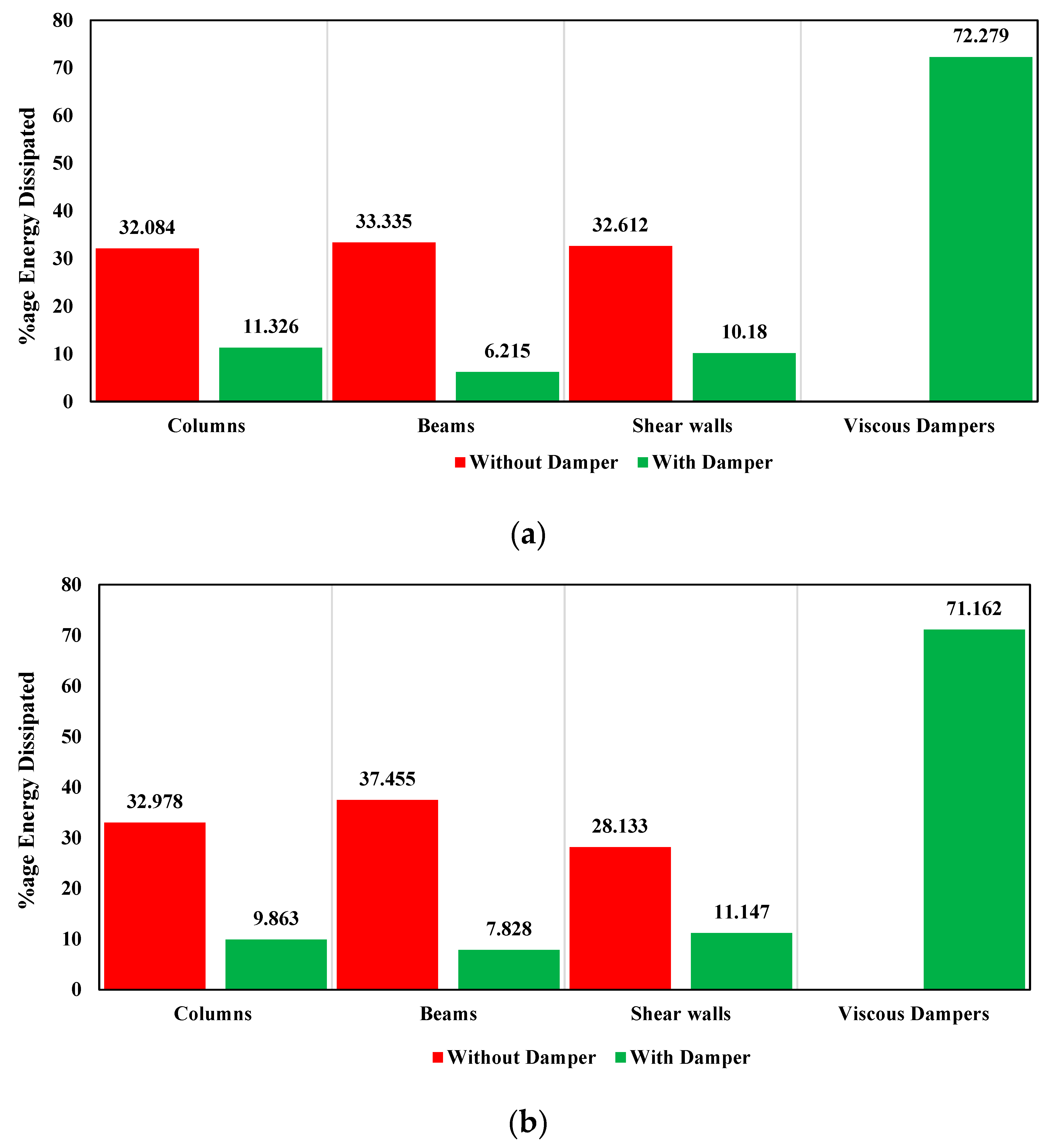
6.4. Energy Dissipation

The energy dissipation by the structural elements in the controlled and uncontrolled structures in the cases of Coalinga−01 (Parkfield−Cholame 2E), Coalinga−01 (Parkfiel−Stone Corral 2E), and Northridge−01 (Palmdale–Hwy 14 and Palmdale) are shown in Figure 15a–c, respectively. The columns, beams, and shear walls dissipate around 32%, 33%, and 32%, respectively, in uncontrolled structures in the case of Coalinga−01 (Parkfield–Cholame 2E) loading. Incorporating the FVDs in the structure, the columns, beams, shear walls, and FVDs dissipate around 11%, 06%, 10%, and 72%, respectively, in the case of Coalinga−01 (Parkfield–Cholame 2E) loading. Therefore, by adding FVDs to the structure, a huge amount of energy is dissipated by the FVDs, and the structural elements, i.e., columns, beams, and shear walls, remain safe from yielding because, without viscous dampers, the energy is dissipated by the inelastic behavior of columns, beams, and shear walls. Similarly, FVDs in the controlled structure, both in the case of Coalinga−01 (Parkfield–Stone Corral 2E) and Northridge−01 (Palmdale–Hwy 14 and Palmdale), dissipate more than 70% energy.

7. Conclusions

Research studies focusing on the practical applications of non-linear fluid viscous dampers for reinforcing the seismic resilience of existing RC structures are very rare in the literature. Moreover, many RC structures in developing countries such as Pakistan are designed on using acceleration values, which are lower than those on the ground. Therefore, the current study focuses on the seismic fortification of existing RC buildings using non-linear fluid viscous dampers. For this purpose, a 33-meter-high building located in Islamabad, Pakistan, has been chosen as a case study for seismic fortification. Two models of the building, with and without fluid viscous dampers (FVDs), were created in Perform 3D for non-linear time-history analysis. Based on the findings of the current study, the following are the main concluding remarks:
Most of the reinforced concrete buildings in Pakistan may not have significant seismic reliance and are designed on spectral acceleration values, which are lower than the original values, according to the BCP 2021. Therefore, these buildings are vulnerable to major seismic events.
  • Compared to other types of retrofitting techniques, such as lateral bracing systems and seismic retrofitting jacketing, FVDs have the advantage of being relatively easy to install, requiring minimal maintenance, and having a long service life. Additionally, FVDs can be integrated into the existing structural system of a building without significantly altering its appearance or function, which may not be the case with other retrofitting techniques.
  • The seismic retrofitting of the case study building with non-linear FVDs has improved its performance in terms of displacement, inter-story drift, and acceleration response against seismic loadings significantly.
  • Installing FVDs in the end bays of the structures/buildings is more beneficial because it reduces the displacement by 36.58% and the inter-story drift by 31.16%. It also resists the torsion of the building.
  • The addition of the non-linear viscous damper to the building had no significant effect on the floor acceleration of the building compared to the building without the non-linear fluid viscous dampers.
  • The fundamental time period of the building with non-linear viscous dampers decreased by 0.51 (s) more than the building without a non-linear viscous damper. This is because of the increased stiffness of the building.
  • More than 70% of the energy is dissipated by FVDs in the controlled retrofitted structure against all three seismic loading cases. In addition, in the retrofitted structure of FVDs, the structural elements, i.e., columns, beams, and shear walls, remain safe against inelastic yielding.
  • Overall, this study suggests that retrofitting existing buildings with non-linear FVDs is a promising approach that significantly improves the seismic reliance of the structure in seismic-prone areas.
It is recommended for future studies that the retrofitting of existing RC structures with non-linear FVDs coupled with bracing be investigated. Moreover, it is suggested that FVDs and metallic yield dampers’ cost-effectiveness investigation should be carried out for retrofitting purposes.

Author Contributions

Conceptualization, R.D.R. and U.J.M.; methodology, R.D.R. and U.J.M.; software, U.J.M. and F.A.N.; validation, M.U.S.; formal analysis, R.D.R. and U.J.M.; investigation, M.U.; resources, R.D.R.; data curation, R.D.R.; writing—original draft preparation, R.D.R.; writing—review and editing, M.U.S., M.U. and F.A.N.; visualization, M.U.S.; supervision, M.U., M.U.S. and F.A.N.; project administration, M.U.S. All authors have read and agreed to the published version of the manuscript.

Funding

This research received no external funding.

Data Availability Statement

The data used in this study is available on request from the corresponding author.

Conflicts of Interest

The authors declare no conflict of interest.

References

  1. Albini, P.; Musson, R.M.W.; Rovida, A.; Locati, M.; Capera, A.A.G.; Viganò, D. The global earthquake history. Earthq. Spectra 2014, 30, 607–624. [Google Scholar] [CrossRef]
  2. Kenny, C. Disaster risk reduction in developing countries: Costs, benefits and institutions. Disasters 2012, 36, 559–588. [Google Scholar] [CrossRef] [PubMed]
  3. Agnew, D.C.; Lee, W.H.K.; Kanamori, H.; Jennings, P.C.; Kisslinger, C. History of seismology. In International Handbook of Earthquake and Engineering Seismology; Academic Press: Cambridge, MA, USA, 2002; Volume 81, pp. 3–11. [Google Scholar]
  4. Bozorgnia, Y.; Bertero, V.V. Earthquake Engineering: From Engineering Seismology to Performance-Based Engineering; CRC Press: Boca Raton, FL, USA, 2004. [Google Scholar]
  5. Kanamori, H.; Brodsky, E.E. The physics of earthquakes. Rep. Prog. Phys. 2004, 67, 1429. [Google Scholar] [CrossRef]
  6. Kusky, T.M. Earthquakes: Plate Tectonics and Earthquake Hazards; Infobase Publishing: New York, NY, USA, 2008. [Google Scholar]
  7. Kanamori, H.; Brodsky, E.E. The physics of earthquakes. Phys. Today 2001, 54, 34–40. [Google Scholar] [CrossRef]
  8. McDermott, T.K.J.; Barry, F.; Tol, R.S.J. Disasters and development: natural disasters, credit constraints, and economic growth. Oxf. Econ. Pap. 2014, 66, 750–773. [Google Scholar] [CrossRef]
  9. Cirella, G.T.; Semenzin, E.; Critto, A.; Marcomini, A. Natural hazard risk assessment and management methodologies review: Europe. In Sustainable Cities and Military Installations; Springer: Berlin/Heidelberg, Germany, 2014; pp. 329–358. [Google Scholar]
  10. Booth, E.D.; Key, D. Earthquake Design Practice for Buildings; Thomas Telford London: London, UK, 2006. [Google Scholar]
  11. Lindeburg, M.R.; McMullin, K.M. Seismic Design of Building Structures: A Professional’s Introduction to Earthquake Forces and Design Details; Professional Publications, Inc.: Belmont, CA, USA, 2014. [Google Scholar]
  12. American Society of Civil Engineers. Seismic Evaluation and Retrofit of Existing Buildings; American Society of Civil Engineers: Reston, VI, USA, 2017. [Google Scholar]
  13. Fakunle, F.; Opiti, C.; Sheikh, A.; Fashina, A. Major barriers to the enforcement and violation of building codes and regulations: A global perspective. SPC J. Environ. Sci. 2020, 2, 12–18. [Google Scholar]
  14. Vaughan, E.; Turner, J. The value and impact of building codes. Environ. Energy Study Inst. White Pap. 2013, 20, 501–517. [Google Scholar]
  15. Valente, M.; Milani, G. Alternative retrofitting strategies to prevent the failure of an under-designed reinforced concrete frame. Eng. Fail. Anal. 2018, 89, 271–285. [Google Scholar] [CrossRef]
  16. Alashkar, Y.; Nazar, S.; Ahmed, M. A comparative study of seismic strengthening of RC building by steel bracings and concrete shear walls. Int. J. Civ. Struct. Eng. Res. 2015, 2, 24–34. [Google Scholar]
  17. Bothara, J.; Brzev, S. A Tutorial: Improving the Seismic Performance of Stone Masonry Buildings; Earthquake Engineering Research Institut: Oakland, CA, USA, 2012. [Google Scholar]
  18. Fukuyama, H.; Sugano, S. Japanese seismic rehabilitation of concrete buildings after the Hyogoken-Nanbu Earthquake. Cem. Concr. Compos. 2000, 22, 59–79. [Google Scholar] [CrossRef]
  19. Calabrese, A.; Spizzuoco, M.; Serino, G.; della Corte, G.; Maddaloni, G. Shaking table investigation of a novel, low-cost, base isolation technology using recycled rubber. Struct. Control Health Monit. 2015, 22, 107–122. [Google Scholar] [CrossRef]
  20. Li, Y.; Ahuja, A.; Padgett, J.E. Review of methods to assess, design for, and mitigate multiple hazards. J. Perform. Constr. Facil. 2012, 26, 104–117. [Google Scholar] [CrossRef]
  21. Singh, M.P.; Moreschi, L.M. Optimal seismic response control with dampers. Earthq. Eng. Struct. Dyn. 2001, 30, 553–572. [Google Scholar] [CrossRef]
  22. Haider, A.; Rehman, Z.U. Evaluation of seismicity of Karachi city in the context of modern building codes. Arab. J. Geosci. 2021, 14, 65. [Google Scholar] [CrossRef]
  23. Sarwar, F.; Iqbal, S.; Qaisar, M.; Rehman, A.; Akhtar, F.; Raza, S.M. Earthquake statistics and earthquake research studies in Pakistan. Open. J. Earthq. Res. 2016, 5, 97. [Google Scholar] [CrossRef]
  24. Sarwar, F.; Iqbal, S.; Kamal, L. An analysis of Pakistan’s local network catalog of earthquake for the period of 1905–2007. Sci. Int. 2011, 23, 13–18. [Google Scholar]
  25. Atkinson, G.M. An overview of developments in seismic hazard analysis. In Proceedings of the 13th World Conference on Earthquake Engineering, Vancouver, BC, Canada, 1–6 August 2004; pp. 1–6. [Google Scholar]
  26. Hassan, W.; Raza, M.F.; Alshameri, B.; Shahzad, A.; Khalid, M.H.; Nawaz, M.N. Statistical interpolation and spatial mapping of geotechnical soil parameters of District Sargodha, Pakistan. Bull. Eng. Geol. Environ. 2023, 82, 37. [Google Scholar] [CrossRef]
  27. Khalid, M.H.; Alshameri, B.; Abid, U. Application of Kriging for development of SPT N value contour maps and USCS-based soil type qualitative contour maps for Islamabad, Pakistan. Env. Earth Sci. 2021, 80, 413. [Google Scholar] [CrossRef]
  28. Shroder, J.F., Jr. Himalaya to the Sea: Geology, Geomorphology and the Quaternary; Routledge: England, UK, 2002. [Google Scholar]
  29. Bacha, A.S.; Shafique, M.; van der Werff, H. Landslide inventory and susceptibility modelling using geospatial tools, in Hunza-Nagar valley, northern Pakistan. J. Mt. Sci. 2018, 15, 1354–1370. [Google Scholar] [CrossRef]
  30. Khan, S.A.; Saeed, Z.; Khan, A.; Hamid, G.; Haider, S.W. Assessment of soil liquefaction potential in defence housing authority, Karachi, Pakistan. Int. J. Econ. Environ. Geol. 2017, 8, 63–68. [Google Scholar]
  31. Heidarzadeh, M.; Satake, K. A combined earthquake–landslide source model for the Tsunami from the 27 November 1945 M w 8.1 Makran earthquake. Bull. Seismol. Soc. Am. 2017, 107, 1033–1040. [Google Scholar] [CrossRef]
  32. Vallage, A.; Klinger, Y.; Grandin, R.; Bhat, H.S.; Pierrot-Deseilligny, M. Inelastic surface deformation during the 2013 Mw 7.7 Balochistan, Pakistan, earthquake. Geology 2015, 43, 1079–1082. [Google Scholar]
  33. Vallage, A.; Klinger, Y.; Lacassin, R.; Delorme, A.; Pierrot-Deseilligny, M. Geological structures control on earthquake ruptures: The Mw7. 7, 2013, Balochistan earthquake, Pakistan. Geophys. Res. Lett. 2016, 43, 10–155. [Google Scholar] [CrossRef]
  34. Rehman, K.; Burton, P.W. Seismicity and seismic hazard parameters in and around Pakistan. J. Seismol. 2020, 24, 635–653. [Google Scholar] [CrossRef]
  35. Dowrick, D.J. Earthquake Resistant Design and Risk Reduction; John Wiley & Sons: Hoboken, NJ, USA, 2009. [Google Scholar]
  36. Bommer, J.J.; Scott, S.G.; Sarma, S.K. Hazard-consistent earthquake scenarios. Soil. Dyn. Earthq. Eng. 2000, 19, 219–231. [Google Scholar] [CrossRef]
  37. Shah, A.; Qureshi, M.A.; Saleem, W.; Naseer, S.; Haq, I. An analysis of Seismic Provisions of Building Code of Pakistan. In Proceeding of the 5th World Engineering Congress (WEC 2013), Torino, Italy, 8–13 September 2013; pp. 23–25. [Google Scholar]
  38. Thermou, G.E.; Elnashai, A.S. Seismic retrofit schemes for RC structures and local-global consequences. Prog. Struct. Eng. Mater. 2006, 8, 1–15. [Google Scholar] [CrossRef]
  39. Faella, C.; Martinelli, E.; Nigro, E. A rational strategy for seismic retrofitting of RC existing buildings. In Proceedings of the 14th World Conference on Earthquake Engineering, Beijing, China, 12–17 October 2008; pp. 12–17. [Google Scholar]
  40. Fib. Seismic Assessment and Retrofit of Reinforced Concrete Buildings; FIB Bulletin No. 24; FIB: Lausanne, Switzerland.
  41. Mazza, F.; Mazza, M.; Vulcano, A. Displacement-based seismic design of hysteretic damped braces for retrofitting in-elevation irregular rc framed structures. Soil. Dyn. Earthq. Eng. 2015, 69, 115–124. [Google Scholar] [CrossRef]
  42. Almeida, A.; Ferreira, R.; Proença, J.M.; Gago, A.S. Seismic retrofit of RC building structures with Buckling Restrained Braces. Eng. Struct. 2017, 130, 14–22. [Google Scholar] [CrossRef]
  43. Giannuzzi, D.; Ballarini, R.; Huckelbridge, A., Jr.; Pollino, M.; Valente, M. Braced ductile shear panel: New seismic-resistant framing system. J. Struct. Eng. 2014, 140, 04013050. [Google Scholar] [CrossRef]
  44. Martinelli, E.; Lima, C.; Faella, C. Towards a rational strategy for seismic retrofitting of RC frames by combining member-and structure-level techniques. In Proceedings of the SMAR2015–Third Conference on Smart Monitoring, Assessment and Rehabilitation of Civil Structures, Antalya, Türkiye, 7–9 September 2015; pp. 6–9. [Google Scholar]
  45. Cao, X.-Y.; Shen, D.; Feng, D.-C.; Wang, C.-L.; Qu, Z.; Wu, G. Seismic retrofitting of existing frame buildings through externally attached sub-structures: State of the art review and future perspectives. J. Build. Eng. 2022, 57, 104904. [Google Scholar] [CrossRef]
  46. Alam, Z.; Zhang, C.; Samali, B. The role of viscoelastic damping on retrofitting seismic performance of asymmetric reinforced concrete structures. Earthq. Eng. Eng. Vib. 2020, 19, 223–237. [Google Scholar] [CrossRef]
  47. Benavent-Climent, A. An energy-based method for seismic retrofit of existing frames using hysteretic dampers. Soil. Dyn. Earthq. Eng. 2011, 31, 1385–1396. [Google Scholar] [CrossRef]
  48. Azad, M.S.; Gani, S.H.A. Comparative study of seismic analysis of multistory buildings with shear walls and bracing systems. Int. J. Adv. Struct. Geotech. Eng. (IJASGE) 2016, 5, 72–77. [Google Scholar]
  49. Siddiqi, Z.A.; Hameed, R.; Akmal, U. Comparison of different bracing systems for tall buildings. Pak. J. Eng. Appl. Sci. 2014, 14, 17–26. [Google Scholar]
  50. Mohammed, N.; Nazrul, I. Behaviour of Multistorey RCC Structure with Different Type of Bracing System (A Software Approach). Int. J. Innov. Res. Sci. Eng. Technol. 2013, 2, 7465–7478. [Google Scholar]
  51. Perera, R. A numerical model to study the seismic retrofit of RC columns with advanced composite jacketing. Compos. B. Eng. 2006, 37, 337–345. [Google Scholar] [CrossRef]
  52. Julio, E.S.; Branco, F.; Silva, V.D. Structural rehabilitation of columns with reinforced concrete jacketing. Prog. Struct. Eng. Mater. 2003, 5, 29–37. [Google Scholar] [CrossRef]
  53. Di Trapani, F.; Malavisi, M.; Marano, G.C.; Sberna, A.P.; Greco, R. Optimal seismic retrofitting of reinforced concrete buildings by steel-jacketing using a genetic algorithm-based framework. Eng. Struct. 2020, 219, 110864. [Google Scholar] [CrossRef]
  54. Fakharifar, M.; Chen, G.; Arezoumandi, M.; ElGawady, M. Hybrid jacketing for rapid repair of seismically damaged reinforced concrete columns. Transp. Res. Rec. 2015, 2522, 70–78. [Google Scholar] [CrossRef]
  55. Bournas, D.A.; Triantafillou, T.C.; Zygouris, K.; Stavropoulos, F. Textile-reinforced mortar versus FRP jacketing in seismic retrofitting of RC columns with continuous or lap-spliced deformed bars. J. Compos. Constr. 2009, 13, 360–371. [Google Scholar] [CrossRef]
  56. Heysami, A. Types of dampers and their seismic performance during an earthquake. Curr. World Environ. 2015, 10, 1002–1015. [Google Scholar] [CrossRef]
  57. Chang, J.C.H.; Soong, T.T. Structural control using active tuned mass dampers. J. Eng. Mech. Div. 1980, 106, 1091–1098. [Google Scholar] [CrossRef]
  58. Bhaskararao, A.V.; Jangid, R.S. Seismic analysis of structures connected with friction dampers. Eng. Struct. 2006, 28, 690–703. [Google Scholar] [CrossRef]
  59. Kim, J. Development of seismic retrofit devices for building structures. Int. J. High-Rise Build. 2019, 8, 221–227. [Google Scholar]
  60. Reinhorn, A.M.; Li, C.; Constantinou, M.C. Experimental and Analytical Investigation of Seismic Retrofit of Structures with Supplemental Damping: Part. 1-Fluid Viscous Damping Devices; National Center for Earthquake Engineering Research: New York, NY, USA, 1995; p. 120. [Google Scholar]
  61. Shah, M.U.; Shah, S.W.; Farooq, S.H.; Usman, M.; Ullah, F. Experimental investigation of tuned liquid column ball damper’s position on vibration control of structure using different fluids. Innov. Infrastruct. Solut. 2023, 8, 111. [Google Scholar] [CrossRef]
  62. Shah, M.U.; Usman, M.; Farooq, S.H.; Rizwan, M. Spring-controlled modified tuned liquid column ball damper for vibration mitigation of structures. J. Sound. Vib. 2023, 545, 117443. [Google Scholar] [CrossRef]
  63. Shah, M.U.; Usman, M.; Farooq, S.H.; Kim, I.H. Effect of tuned spring on vibration control performance of modified liquid column ball damper. Appl. Sci. 2022, 12, 318. [Google Scholar] [CrossRef]
  64. Mevada, S.; Jangid, R. Seismic response of asymmetric systems with linear and non-linear viscous dampers. Int. J. Adv. Struct. Eng. (IJASE) 2012, 4, 1–20. [Google Scholar] [CrossRef]
  65. Lavan, O.; Levy, R. Optimal design of supplemental viscous dampers for linear framed structures. Earthq. Eng. Struct. Dyn. 2006, 35, 337–356. [Google Scholar] [CrossRef]
  66. Lin, W.; Chopra, A.K. Earthquake response of elastic SDF systems with non-linear fluid viscous dampers. Earthq. Eng. Struct. Dyn. 2002, 31, 1623–1642. [Google Scholar] [CrossRef]
  67. Narkhede, D.I.; Sinha, R. Behavior of nonlinear fluid viscous dampers for control of shock vibrations. J. Sound. Vib. 2014, 333, 80–98. [Google Scholar] [CrossRef]
  68. Xie, R.; Rodgers, G.; Sullivan, T. Effect of Damper Sub-System Stiffness on the Response of a Single Degree of Freedom System Equipped with a Viscous Damper. J. Earthq. Eng. 2021, 26, 5907–5926. [Google Scholar] [CrossRef]
  69. Mcnamara, R.J.; Taylor, D.P. Fluid viscous dampers for high-rise buildings. Struct. Des. Tall Spec. Build. 2003, 12, 145–154. [Google Scholar] [CrossRef]
  70. Zhou, Y.; Sebaq, M.S.; Xiao, Y. Energy dissipation demand and distribution for multi-story buildings with fluid viscous dampers. Eng. Struct. 2022, 253, 113813. [Google Scholar] [CrossRef]
  71. Hou, C.-Y. Fluid dynamics and behavior of nonlinear viscous fluid dampers. J. Struct. Eng. 2008, 134, 56–63. [Google Scholar] [CrossRef]
  72. Armouti, N.S. Effect of dampers on seismic demand of short period structures in deep cohesionless sites. Adv. Steel Constr. 2011, 7, 192–205. [Google Scholar]
  73. Ras, A.; Boumechra, N. Seismic energy dissipation study of linear fluid viscous dampers in steel structure design. Alex. Eng. J. 2016, 55, 2821–2832. [Google Scholar] [CrossRef]
  74. Mrad, C.; Titirla, M.D.; Larbi, W. Comparison of Strengthening Solutions with Optimized Passive Energy Dissipation Systems in Symmetric Buildings. Appl. Sci. 2021, 11, 10103. [Google Scholar] [CrossRef]
  75. Castellano, M.G.; Borrella, R.; Infanti, S.; Gattulli, V. Experimental characterization of nonlinear fluid viscous dampers according to the New European Standard. In Proceedings of the EACS 2012, Paper No. 143, 5th European Conference on Structural Control, Genoa, Italy, 18–20 November 2012; pp. 18–20. [Google Scholar]
  76. De Domenico, D.; Ricciardi, G.; Takewaki, I. Design strategies of viscous dampers for seismic protection of building structures: A review. Soil. Dyn. Earthq. Eng. 2019, 118, 144–165. [Google Scholar] [CrossRef]
  77. Building Seismic Safety Council. NEHRP Commentary on the Guidelines for the Seismic Rehabilitation of Buildings (FEMA Publication 274); ATC-33 Project; Building Seismic Safety Council: Washington, DC, USA, 1997. [Google Scholar]
  78. Jiang, H.J.; Liu, L.E. Numerical analysis of RC shear walls under cyclic loading by Perform-3D. Adv. Mat. Res. Trans. Tech. Publ. 2011, 250–253, 2253–2257. [Google Scholar] [CrossRef]
  79. De Domenico, D.; Hajirasouliha, I. Multi-level performance-based design optimisation of steel frames with nonlinear viscous dampers. Bull. Earthq. Eng. 2021, 19, 5015–5049. [Google Scholar] [CrossRef]
  80. Akcelyan, S.; Lignos, D.G.; Hikino, T.; Nakashima, M. Evaluation of simplified and state-of-the-art analysis procedures for steel frame buildings equipped with supplemental damping devices based on E-Defense full-scale shake table tests. J. Struct. Eng. 2016, 142, 04016024. [Google Scholar] [CrossRef]
  81. Wang, S. Enhancing Seismic Performance of Tall Buildings by Optimal Design of Supplemental Energy-Dissipation Devices; University of California: Berkeley, CA, USA, 2017. [Google Scholar]
  82. Pineda, A.C.L.; Amortegui, L.F.G.; Chesi, C. Use of viscous fluid dampers for the improvement of the seismic response of RC structures. Vibroengineering Procedia 2019, 23, 87–92. [Google Scholar] [CrossRef]
  83. Bazzurro, P.; Cornell, C.A. Seismic hazard analysis of nonlinear structures. I: Methodology. J. Struct. Eng. 1994, 120, 3320–3344. [Google Scholar] [CrossRef]
  84. Lin, T.; Haselton, C.B.; Baker, J.W. Conditional spectrum-based ground motion selection. Part I: Hazard consistency for risk-based assessments. Earthq. Eng. Struct. Dyn. 2013, 42, 1847–1865. [Google Scholar] [CrossRef]
  85. Zaman, S.; Ornthammarath, T.; Warnitchai, P. Probabilistic seismic hazard maps for Pakistan. In Proceeding of the 15th World Conference on Earthquake Engineering, Lisbon, Portugal, 24–28 September 2012. [Google Scholar]
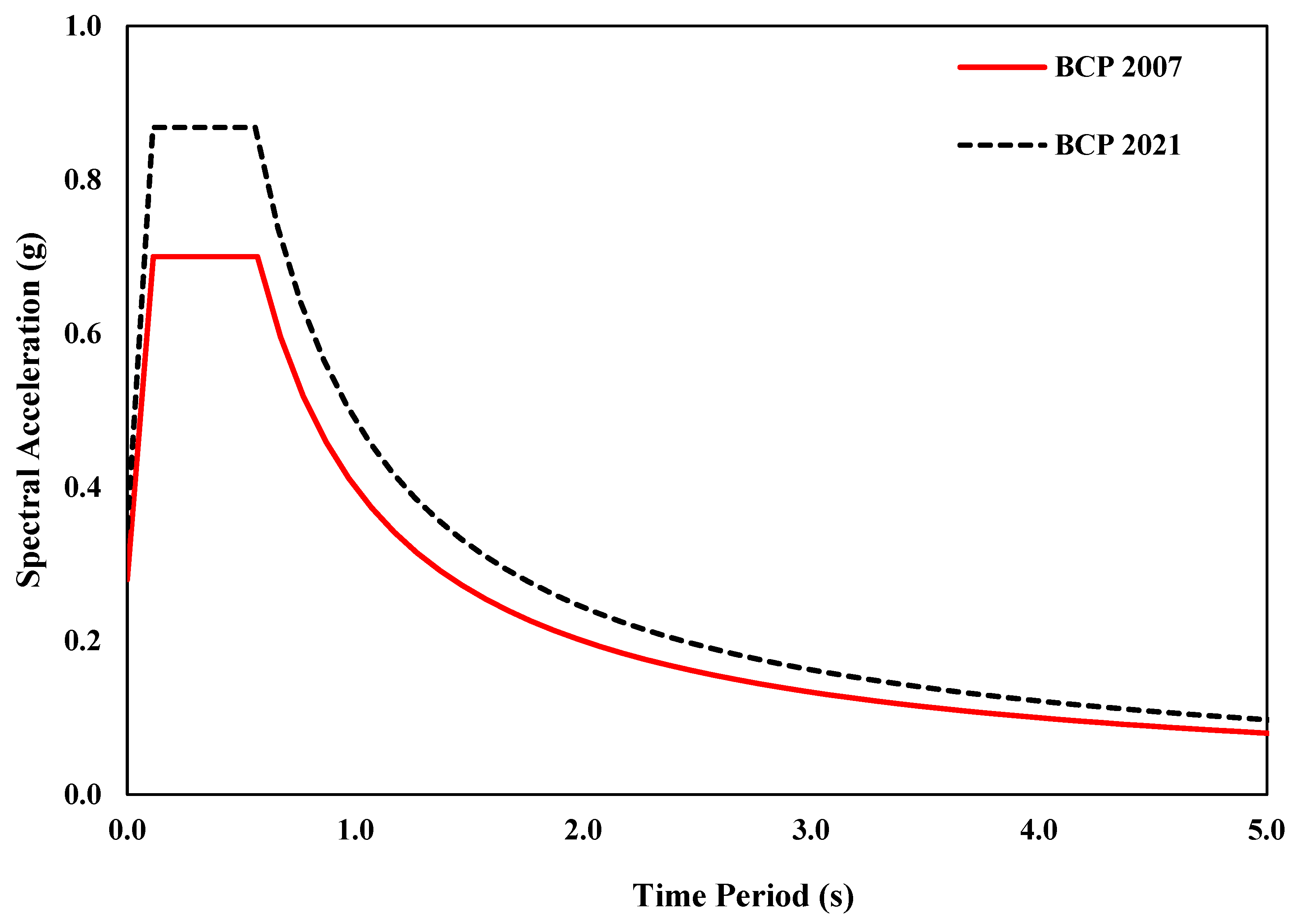
Figure 1. Comparison of response spectrum of BCP 2007 and BCP 2021.
Actuators 12 00175 g001
Figure 2. Floor plan and a finite 3D element model of the case study building in ETABS.
Actuators 12 00175 g002
Figure 3. Comparison of the responses of the structure according to BCP 2007 and BCP 2021. (a) Displacement response, (b) inter-story drift response, (c) shear force response, and (d) moment response.
Actuators 12 00175 g003
Figure 4. A labelled figure showcases the inner workings of a typical fluid viscous damper (FVD). Reprinted with permission from [67].
Actuators 12 00175 g004
Figure 5. (a) Force velocity relationship of FVDs. (b) Force displacement relationship of FVDs. In the case of linear dampers, the damper force increases linearly with the damper velocity, as shown in (a). In the case of a non-linear damper, the damper force decreases with an increase in the damper velocity. Similarly, non-linear viscous dampers dissipate more energy than linear viscous dampers at the same excitation. Reprinted with permission from [74].
Actuators 12 00175 g005
Figure 6. (a) A 3D finite element model of the building in Perform 3D without fluid viscous damper, and (b) bay of structure without dampers. (c) A 3D finite element model of building with fluid viscous damper, and (d) bay of structure with fluid viscous damper.
Actuators 12 00175 g006
Figure 7. A 5% damped response spectrum.
Actuators 12 00175 g007
Figure 8. (a,b) Time histories of Coalinga−01 (1983) recording station Parkfield−Cholame 2E in H1 and H2 direction, respectively. (c,d) Time histories of Coalinga−01 (1983) recording station Parkfield −Stone Corral 2E in H1 and H2 direction, respectively. (e,f) Time histories of Northridge−01 (1994) recording station Palmdale–Hwy 14 and Palmdale in H1 and H2 direction, respectively.
Actuators 12 00175 g008aActuators 12 00175 g008b
Figure 9. Modal deformed shape of the building with and without non-linear fluid viscous dampers for (a,d) mode 1, (b,e) mode 2, and (c,f) mode 3.
Actuators 12 00175 g009
Figure 10. Displacement responses of the structure with and without fluid viscous dampers under seismic loadings: (a) Coalinga-01 (Parkfield–Cholame 2E), (b) Coalinga-01 (Parkfield–Stone Corral 2E), and (c) Northridge-01 (Palmdale–Hwy 14 and Palmdale).
Actuators 12 00175 g010
Figure 11. Drift responses of the structure with and without fluid viscous dampers under seismic loadings (a) Coalinga-01 (Parkfield–Cholame 2E), (b) Coalinga-01 (Parkfield–Stone Corral 2E), and (c) Northridge-01 (Palmdale–Hwy 14 and Palmdale).
Actuators 12 00175 g011
Figure 12. Acceleration responses of the structure with and without fluid viscous dampers under seismic loadings (a) Coalinga-01 (Parkfield–Cholame 2E), (b) Coalinga-01 (Parkfield–Stone Corral 2E), and (c) Northridge-01 (Palmdale–Hwy 14 and Palmdale).
Actuators 12 00175 g012
Figure 13. Acceleration time−history responses of the top story with and without fluid viscous dampers under (a) Coalinga−01 (Parkfield−Cholame 2E), (b) Coalinga−01 (Parkfield−Stone Corral 2E), and (c) Northridge−01 (Palmdale−Hwy 14 and Palmdale).
Actuators 12 00175 g013aActuators 12 00175 g013b
Figure 14. Displacement time−history responses of the top story with and without fluid viscous dampers under (a) Coalinga−01 (Parkfield−Cholame 2E), (b) Coalinga−01 (Parkfield−Stone Corral 2E), and (c) Northridge−01 (Palmdale−Hwy14 and Palmdale).
Actuators 12 00175 g014aActuators 12 00175 g014b
Figure 15. Percentage (% age) energy dissipation of structural elements of the buildings with and without fluid viscous dampers under (a) Coalinga−01 (Parkfield–Cholame 2E), (b) Coalinga−01 (Parkfield−Stone-Corral 2E), and (c) Northridge−01 (Palmdale−Hwy14 and Palmdale).
Actuators 12 00175 g015aActuators 12 00175 g015b
Table 1. Parameters of the building code of Pakistan 2007 and 2021.
BCP 2007 ParametersBCP 2021 Parameters
Seismic Zone 2BShort-period spectral acceleration (Ss)1.302
Closest distance to the seismic source (km) for Na> 10Long-period spectral acceleration (S1)0.381
Closest distance to the seismic source (km) for Nv> 15Site coefficient (Fa)1
Near source factor (Na)1Site coefficient (Fv)1.91904
Near source factor (Nv)1Site-modified spectral acceleration (SMS)1.302
Seismic zone factor (Z)0.2Site-modified spectral acceleration (SM1)0.731
Seismic coefficient (Ca)0.28Design-level spectral acceleration (SDS)0.868
Seismic coefficient (Cv)0.4Design-level spectral acceleration (SD1)0.487
Table 2. Salient features of case study building.
Building Height (m)33
No. of Stories9
Specified compressive strength of concrete f’c (MPa)RC columns35
RC beams and slabs20.68
RC walls27.57
Specified yield strength of longitudinal steel bar in RC walls and RC columns fy (MPa) 414
Natural period of vibrational modes (s)Mode 1 (X direction)1.34
Mode 2 (Y direction)1.18
Mode 3 (Torsional)0.87
Table 3. Properties of ground motion selected in the current study.
Earthquake Name (year)Station NameMagnitudeMechanismRjb (km)Rrup
(km)
Vs30 (m/s)
Coalinga-01 (1983)Parkfield–Cholame 2E6.36Reverse41.9942.92522.74
Coalinga-01 (1983)Parkfield–Stone Corral 2E6.36Reverse35.2936.4566.33
Northridge-01 (1994)Palmdale–Hwy 14 and Palmdale6.69Reverse41.3741.67551.56
Table 4. Modal participation mass of structure without and with dampers.
Structure without DampersStructure with Dampers
Modal Participation Mass RatioModal Participation Mass Ratio
Mode 1 (Ux)0.59210.6086
Mode 2 (Uy)0.57900.6079
Mode 3 (Rz)0.52440.5471
Disclaimer/Publisher’s Note: The statements, opinions and data contained in all publications are solely those of the individual author(s) and contributor(s) and not of MDPI and/or the editor(s). MDPI and/or the editor(s) disclaim responsibility for any injury to people or property resulting from any ideas, methods, instructions or products referred to in the content.

