
Influence of Nonlinear Characteristics of Planetary Flywheel Inerter Actuator on Vehicle Active Suspension Performance

1
School of Information Science and Engineering, Zhejiang Sci-Tech University, Hangzhou 310018, China
2
Research Institute of Zhejiang University—Taizhou, Taizhou 317600, China
3
School of Mechanical Engineering, Zhejiang University, Hangzhou 310058, China
*
Authors to whom correspondence should be addressed.
Actuators 2023, 12(6), 252; https://doi.org/10.3390/act12060252
Submission received: 11 May 2023
/
Revised: 5 June 2023
/
Accepted: 15 June 2023
/
Published: 16 June 2023
(This article belongs to the Section Actuators for Land Transport)
Abstract
:The planetary flywheel can significantly reduce the weight of the flywheel, allowing the inerter to be lightweight. When a planetary flywheel ball screw inerter-based active actuator is used in a vehicle suspension system, the nonlinear features of the actuator affect vehicle performance. The planetary flywheel inerter actuator’s nonlinear dynamic model is constructed in this study based on the dynamic features of the planetary flywheel ball screw inerter and the electromagnetic torque generating mechanism of the permanent magnet synchronous motor. The impact of ball screw–nut friction, transmission clearance, planetary gear friction, and gear backlash on the performance of an active tuned inerter damper suspension is then investigated. As a result, the impact and sensitivity of numerous nonlinear parameters on suspension performance are shown, providing a theoretical foundation for the design of planetary flywheel inerter actuator and active inerter suspension.
1. Introduction
Suspension refers to the components intended to decrease vibration between the wheels and the vehicle’s body, which is critical to the vehicle’s comfort and safety. Active suspension can control the actuator’s output force based on the suspension motion to meet the changing parameter requirements of the suspension system in different road conditions, greatly improving suspension performance [1].
In recent years, the use of inerters in suspension has emerged as a new study area. The inerter is a novel mechanical device with two terminals whose output force is proportional to their relative acceleration [2]. The inerter is a kind of inertial component that performs dynamically, comparable to the mass body in the mechanical network, and may generate inertial force more than a hundred times its own mass. As a result, the mechanical network design is expanded from two fundamental components of elasticity and damping to three elements of inertia, elasticity, and damping. This considerably improves mechanical network implementation [3]. As a result of their outstanding mechanical qualities, inerters have been extensively employed in the area of vibration reduction, such as buildings [4,5,6], cables [7,8], robot joints [9,10], automobiles [11,12,13,14], aircrafts [15,16], etc. Inerters come in a variety of configurations, including fluid [17], ball screw [18,19,20], rack and pinion [21], and others. Among them, the friction of the ball screw type inerter is lower, which may lessen the impact of clearance by employing the nut pre-tightening force, and the inertance of the same mass is higher, resulting in superior overall performance [22]. On the basis of the ball screw inerter, substituting a single flywheel with a planetary flywheel may boost inertance and achieve the inerter’s lightweight design [23].
A tuned mass damper (TMD) is an additional device that can reduce the vibration of the main structure [24]. Inerters and TMDs have recently been combined to provide a variety of innovative shock absorption technologies [25,26,27]. In-depth research has been conducted on how the inerter’s placement in the tuned damper affects the damping performance [28]. The tuned inerter damper (TID) is a novel invention that directly replaces the mass in the TMD with an inerter, making it more appropriate for applications where the shock absorption system must be lightweight [5]. Active tuned inerter suspension is a novel kind of active suspension that may shift the actuator’s inertial mass from a negative to a positive factor in suspension performance [29]. By incorporating the planetary flywheel inerter actuator into the active tuned inerter suspension, the suspension system can be made lighter. However, in practice, the mechanical mechanism used to realize the inerter has nonlinear mechanical properties [30,31,32,33,34,35]. Nonlinear features such as inerter friction have been found in previous research to have a negative impact on suspension performance [36,37,38,39]. The planetary flywheel inerter actuator has a more sophisticated construction with more nonlinear variables. At the moment, the nonlinear effect of the actuator on active suspension has not been thoroughly investigated.
A nonlinear model of the planetary flywheel type ball screw inerter actuator, which includes many nonlinear factors existing in the ball screw–nut pair and the planetary gear, is established in order to better understand the influence of the nonlinear factors existing in the planetary flywheel inerter actuator on the performance of active suspension. The mode and sensitivity of different nonlinear factors influence active suspension performance are investigated. It serves as a theoretical foundation for the development of planetary flywheel ball screw type inerter and active tuned inerter damping suspension. This article is organized as follows: The structure of the planetary flywheel inerter actuator is developed in Section 2, and the actuator’s nonlinear dynamic model is constructed. Section 3 introduces the theory of active tuned inerter suspension and the suspension performance measures. Section 4 compares the performance of the suspension with linear inerter actuator models to the performance of the suspension with nonlinear inerter actuator models. Section 5 and Section 6 examine the impact of nonlinear features in ball screw and planetary flywheel on suspension performance, respectively, and explore the essential aspects of actuator structure design. This article concludes in Section 7.
2. Structure of a Planetary Flywheel Inerter Actuator and Its Nonlinear Dynamic Model
2.1. Structural Design and Fundamental Mechanical Model of Planetary Flywheel Inerter Actuator
Reference [23] created a planetary flywheel-equipped ball screw type inerter that may achieve a higher inertance for a given flywheel weight, due to the compound motion of the flywheel’s revolution and rotation. To produce the planetary flywheel type active inerter actuator, the shell of a permanent magnet synchronous motor (PMSM) is attached to the outer gear ring, and the output shaft of the motor is coupled with the planetary flywheel carrier, as illustrated in Figure 1.
2.2. Mechanical Model of Passive Planetary Flywheel Inerter
Figure 2 depicts a dynamic model suggested by reference [23] that includes the nonlinear factors of ball screw and planetary flywheel. The experimental results demonstrate that the model accurately represents the dynamic properties of the planetary flywheel inerter.
In the model, ks is the screw–nut pair’s axial stiffness, cs is the screw–nut pair’s axial damping coefficient, ε is the axial clearance between the nut and the screw, and x3 is the screw’s axial displacement. Fa is the screw’s force applied to the flywheel. The axial driving force going from the nut to the screw is denoted by Fd, and its equation is provided in Equation (1).
The total friction of the screw–nut pair and the bearing, denoted by Ff, can be calculated from the total friction torque Tf. The friction torque Tf is mainly composed of static and viscous friction torques, as illustrated in Equation (2).
where Tc is the static friction torque coefficient of the screw–nut pair, Tv is the viscous friction torque coefficient of the screw–nut pair, and θ is the angle of the screw. The planetary flywheel’s nonlinear dynamic model is shown in Figure 2 by the dotted line. Figure 3 shows an additional depiction of the planetary flywheel model. In the model, θs represents the planetary flywheel carrier’s rotation angle, xs represents the displacement of the planetary flywheel carrier along the action line, θp represents the planetary flywheel’s rotation angle, xp represents the displacement of the planetary flywheel along the action line, N represents the number of planetary gears, mpe represents the equivalent mass of the planetary gear rotation, mre represents the equivalent mass of the planetary gear revolution, and mse represents the equivalent mass of planetary flywheel carrier rotation. kri denotes the meshing stiffness of the meshing gear pair along the action line, cri the gear pair’s meshing damping coefficient, and gri the gear backlash. The meshing force between the planetary gear and the outer ring gear is represented by Fpi, and its equation is illustrated in Equation (3).
Tfpi is the equivalent friction torque on the planetary gear’s rotation axis, and its expression is presented in Equation (4).
Tfpm is static friction torque coefficient of the gear, while Tfpv denotes the gear viscous friction torque coefficient.
2.3. Dynamic Model of Planetary Flywheel Inerter Actuator
As shown in Equation (5), the electromagnetic torque Te of a permanent magnet synchronous motor is proportional to the motor current iq.
where Pn represents the number of pole pairs in the motor stator winding, ψf represents the motor rotor flux, and iq represents the motor current. Pn is defined by the motor stator design, while ψf is created by the permanent magnet mounted on the rotor, which is dictated by the rotor design. The combination of these two coefficients yields a constant that describes the proportionality coefficient of electromagnetic torque to motor current, known as the torque constant kt.
The dynamics model of the active inerter actuator can be comparable to an active power module linked in parallel to the planetary flywheel inerter dynamics model. Figure 4 depicts the dynamic model of the active inerter actuator.
The inerter actuator’s two terminals are the piston rod and the mounting flange. The inertia of the planetary flywheel generates a passive force Fd at both terminals of the actuator when the piston rod and the mounting flange move relative to each other. When the motor actively applies torque, the active inerter actuator may output the active force FA as Equation (6) when the transmission principle of the ball screw–nut pair is used.
As shown in Equation (7), the inerter actuator’s output force F is the sum of the passive force Fd and active force FA.
The simulation model is constructed using the dynamic model of the planetary flywheel inerter actuator shown in Figure 5.
3. Structure and Performance Measure of Active Inerter Suspension
Figure 6 depicts the construction of the active tuned inerter damping (ATID) suspension system, which is constructed by replacing the passive inerter in the passive TID suspension with an active inerter actuator. In the diagram, ms represents the sprung mass, mu represents the unsprung mass, K represents the main spring stiffness, Kt represents the tire stiffness, b represents the inerter inertance, k represents the tuned spring stiffness, and c represents the tuned damping coefficient. As part of TID, the inherent inertia of the active actuator has been transformed from a negative to a positive factor that may be exploited to significantly increase the damping performance of the active suspension.
Since the inerter is a two-terminal device, vibration excitation from the unsprung mass is introduced. The active actuator should generate a compensation force proportional to the acceleration of the sprung mass to reduce the influence of unsprung vibration as Equation (8), where r is the compensation coefficient.
Sprung acceleration and tire load are the two most important measures for evaluating vehicle suspension. The former is more important for ride comfort, while the latter is more important for vehicle handling safety. When the vehicle is driven at a constant speed on a random road, the numerical integration technique is used to compute the root-mean-square (RMS) value of the vibration response of the suspension measure, as shown in Equation (9). The lower the RMS value, the better the suspension’s performance.
where is the time-frequency power spectral density of the road surface speed roughness, as defined in Equation (10)
where n0 is the reference spatial frequency, Gq(n0)is the value of the road surface power spectral density at n0, and μ is the vehicle speed.
4. Comparison of Suspension Performance with Linear/Nonlinear Actuator Models
To comprehend the impact of nonlinear inerter actuator variables on suspension performance, the linear inerter actuator model, the nonlinear model of a typical single flywheel, and the nonlinear model of a planetary flywheel are all put in the suspension model shown in Figure 6. Except for the inerter actuator, the linear model is utilized for the remaining suspension parts, and the fundamental values are provided in Table 1. Reference [23] developed a nonlinear model of an inerter that took into account the friction and clearance of a planetary flywheel and a ball screw, and tested the nonlinear parameters to identify them. According to the test findings, the model can accurately represent the dynamic properties of a ball screw inerter with a planetary flywheel. The study in this article is based on the nonlinear parameters acquired from the reference [23], as given in Table 2.
When the compensation coefficient r is zero, the suspension degenerates into the passive TID suspension, according to reference [29]. The damping effect is greater when r is higher, but the actuator must have a higher output power. The active TID suspension’s compensation coefficient in this study is set at r = 300 kg. When the vehicle travels on a Class B road at a speed of 72 km/h, which is within a tolerable range, the actuator’s highest output power is 57.1 W, and the root mean square value of the output power is 10.5 W. When the linear model of the inerter, the nonlinear model with the typical single flywheel (SF), and the nonlinear model with the planetary flywheel (PF) are employed, the amplitude–frequency characteristics of each measure for the passive TID and ATID suspension are obtained, as shown in Figure 7.
Figure 7 shows that the nonlinear features in the inerter actuator only impact the suspension’s characteristics in the low frequency range. When compared to the amplitude–frequency characteristics of the suspension using the linear model, the low frequency resonance peak of the nonlinear suspension has a greater degree of uplift, which is harmful for suspension performance. The nonlinearity of the ball screw is mostly responsible for this negative impact. When a nonlinear actuator model is utilized, the amplitude–frequency characteristics of vehicle sprung acceleration and tire load improve when the compensation coefficient is raised, but not as much as when a linear inerter is used.
When the compensation coefficient r is zero, the amplitude–frequency characteristics of the suspension with a typical single flywheel and a planetary flywheel are almost identical. When the compensation coefficient increases, the nonlinearity of the planetary flywheel has a negative impact on suspension performance, but it is less severe than that of the ball screw. As a result, the nonlinear features of the planetary flywheel and the ball screw have negative impacts on the suspension, with the nonlinearity from the ball screw being the most significant.
5. The Effect of Ball Screw Nonlinear Factors on the Performance of Active Inerter Suspension
The most significant nonlinear factors in the dynamic model of a ball screw inerter are static friction, viscous friction, and screw–nut pair clearance. The nonlinear parameters of the ball screw are enlarged within a reasonable range, and relationships are drawn between the main measures of suspension and the nonlinear parameters.
5.1. The Effect of Ball Screw Static Friction
The static friction torque coefficient of the screw–nut pair Tc is the quantity that defines the static friction of the screw–nut pair. We set the compensation coefficient r = 300 kg and raised Tc from 0 to 2 N‧m. Figure 8 depicts the relationship between sprung acceleration, tire load measure, and screw–nut static friction, where the ordinate shows the ratio of the nonlinear suspension measure value to the same measure value of the linear suspension. Figure 9 depicts the amplitude–frequency characteristics of vehicle sprung acceleration and tire load when Tc is 0.05 N‧m, 0.1 N‧m, and 0.2 N‧m.
The performance of the nonlinear suspension with static friction torque of the screw–nut pair is shown in Figure 8 to be poorer than that of the ideal linear suspension. The performance of the suspension degrades as the static friction torque increases. The suspension performance stays steady when the static friction value grows to a certain level. Figure 9 illustrates that the less the static friction torque of the screw–nut pair, the smaller the amplitude in the low-frequency region of the suspension, and the closer its amplitude–frequency characteristics are to the suspension using the linear model.
5.2. The Effect of Ball Screw Viscous Friction
The viscous friction torque coefficient of the screw–nut pair Tv is the key parameter that defines the viscous friction of the screw–nut pair. We set the compensation coefficient r = 300 kg and increased Tv from 0 to 0.03 N‧m. Figure 10 depicts the relationship between the sprung acceleration, the tire load measure, and the ball screw viscous friction. Figure 11 shows the amplitude–frequency characteristics of sprung acceleration and tire load when Tv is 6.8 × 10⁻⁴ N‧m‧s‧rad−1, 1.4 × 10⁻³ N‧m‧s‧rad−1, and 2.7 × 10⁻³ N‧m‧s‧rad−1.
The impact of viscosity and static friction on the ride comfort measure is similar, as shown in Figure 10. When the friction of the screw–nut pair is minimized, the RMS value of each measure of the nonlinear actuator model suspension is close to that of the linear actuator model suspension. Figure 11 shows that the lower the friction of the screw–nut pair, the smaller the amplitude of the suspension’s low-frequency resonance peak, and the closer its amplitude–frequency characteristics are to the suspension employing the linear model.
5.3. The Effect of the Screw–Nut Pair Clearance
We set the compensation coefficient r = 300 kg and increased the screw–nut pair clearance from 0 to 1 mm. Figure 12 depicts the relationship between the sprung acceleration, tire load measure and the screw–nut pair clearance. Figure 13 shows the amplitude–frequency characteristics of suspension and its partial amplification diagram at around 1.5 Hz when ε is 10−5 m, 10−6 m and 10−7 m.
As seen in Figure 12 and Figure 13, increasing the clearance causes the suspension measures to worsen, although only slightly.
To summarize, the friction and clearance of the screw–nut pair will degrade suspension performance, with static friction being the most critical influence. Because the clearance has little effect on suspension performance within a certain range, properly relaxing the clearance can reduce the screw–nut pair’s pre-tightening force and friction. However, when the clearance is too large, it will cause a number of negative effects, including increased impact between the screw and nut and a decrease in life. The reduced viscous friction coefficient is also beneficial for suspension performance, but it is not the deciding factor. Furthermore, according to Ff = (2π/P)‧Tf, increasing the screw lead can reduce the ratio of the screw–nut pair’s friction torque to the equivalent axial friction force of the inerter, which is also an effective way to overcome the adverse effects of friction.
6. The Effect of Planetary Flywheel Nonlinear Factors on the Performance of Active Inerter Suspension
The primary nonlinear factors in the dynamic model of the planetary flywheel are static friction torque, viscous friction torque, and gear backlash. The planetary flywheel’s nonlinear parameters are extended in an acceptable range, and the relationships between the main suspension measures and the nonlinear parameters are drawn.
6.1. The Effect of Planetary Flywheel Static Friction
The static friction torque coefficient of the planetary gear to the axis of rotation Tfpm is the fundamental parameter determining the static friction of planetary gear. We set r = 300 kg as the compensation coefficient and increased Tfpm from 0 to 8 × 10⁻³ N‧m. Figure 14 depicts the relationship between the gear static friction torque coefficient and the value of each suspension measure, where the ordinate indicating the ratio of the measure of suspension with planetary flywheel to the suspension with typical single flywheel. Figure 15 depicts the amplitude–frequency characteristics of suspension and its partial amplification diagram at around 1.5 Hz when Tfpm is 8 × 10⁻⁴ N‧m, 4 × 10⁻⁴ N‧m and 8 × 10⁻⁵ N‧m.
Figure 14 shows that reducing the static friction of the gear improves suspension performance, although the change range is quite small. Figure 15 illustrates that the lower the gear static friction, the lower the low frequency resonance peak of the suspension. In general, the effect of gear static friction on suspension performance is negligible and may be disregarded.
6.2. The Effect of Planetary Flywheel Viscous Friction
The viscous friction torque coefficient of the planetary gear on the axis of rotation Tfpv is the fundamental parameter that defines the viscous friction of the planetary gear. Figure 16 depicts the relationship between the gear viscous friction coefficient and the value of each suspension measure when the compensation coefficient r = 300 kg and Tfpv is raised from 0 to 1.4 × 10⁻³ N‧m. Figure 17 depicts the amplitude–frequency characteristics of suspension and its partial amplification diagram at around 1.5 Hz when Tfpv is 1.4 × 10⁻⁴ N‧m, 6.8 × 10⁻⁵ N‧m and 1.4 × 10⁻⁵ N‧m.
Figure 16 shows that when the viscous friction of the gear is lowered, all of the measure values decrease, and the suspension performance improves. Figure 17 shows that the less the gear viscous friction, the smaller the amplitude of the suspension’s low frequency resonance peak.
In general, gear viscous friction has a greater impact on suspension performance than static friction, which is the primary cause for the difference in dynamic characteristics between planetary flywheel and typical single flywheel, as well as the worsening of suspension performance.
6.3. The Effect of Gear Backlash
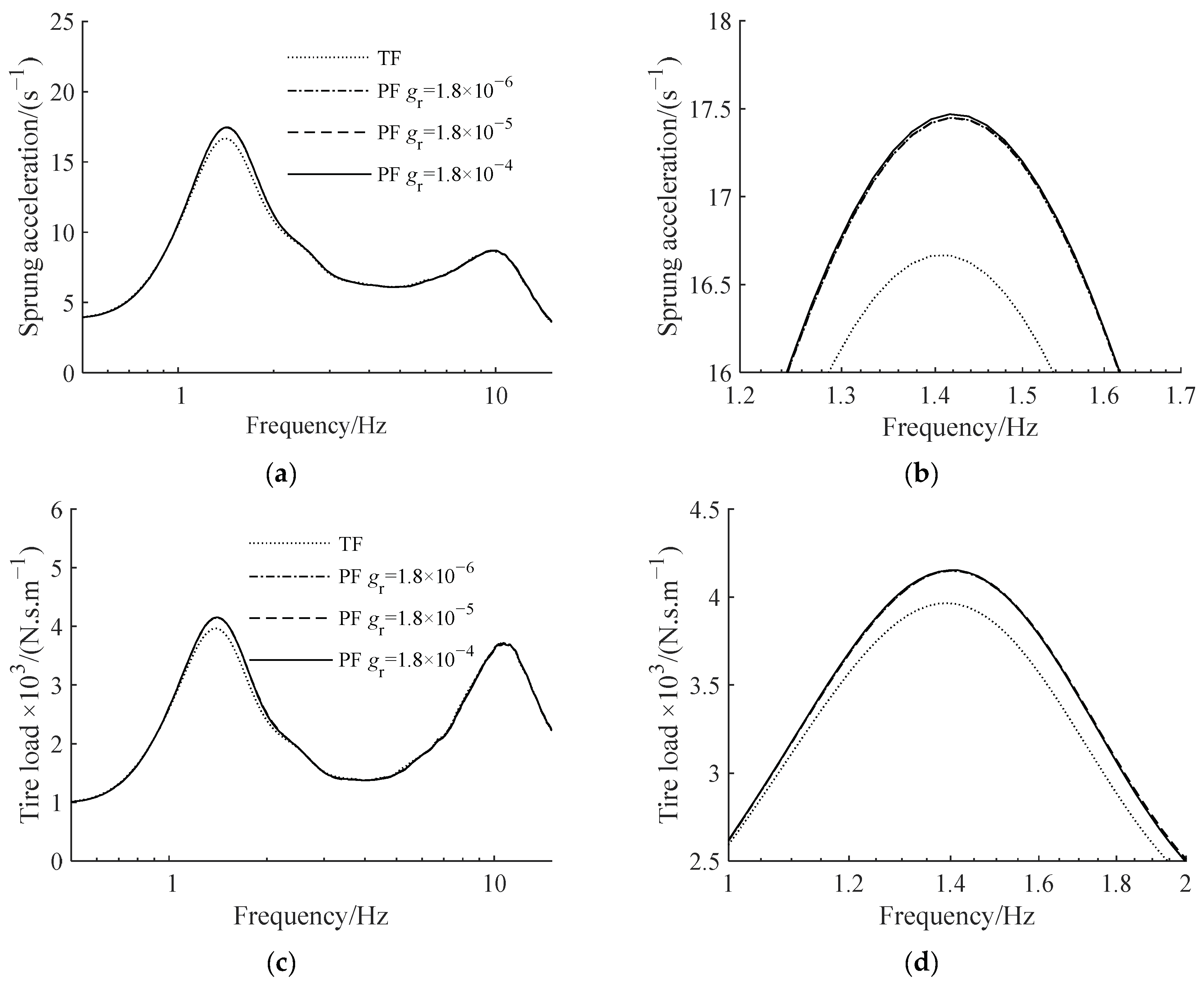
We increased the gear backlash gr from 0 to 2 mm and set the compensation coefficient r = 300 kg. Figure 18 depicts the relationship between gear backlash and the value of each suspension measure. Figure 19 depicts the amplitude–frequency characteristics of suspension and its partial amplification diagram at around 1.5 Hz when gr is 1.8 × 10⁻⁶ m, 1.8 × 10⁻⁵ m and 1.8 × 10⁻⁴ m.
Figure 18 indicates that a small increase in gear backlash improves suspension performance, although only marginally. Figure 19 shows that the characteristic curves of the planetary flywheel suspensions are practically coincident, showing that the actual influence of the gear backlash on suspension performance is quite modest and may be ignored.
To summarize, planetary gear friction will have a detrimental influence on suspension performance, with viscous friction being the most vital contribution. Reducing the viscous friction coefficient helps to overcome the negative impacts of planetary gear friction, so that the planetary flywheel and the typical single flywheel have similar dynamic characteristics, enhancing suspension performance.
7. Conclusions
For the ATID suspension, the nonlinear factors in the ball screw and planetary flywheel have little effect on the high-frequency characteristics of the suspension but will increase the amplitude of the suspension’s low-frequency resonance peak, which will have a negative impact on suspension performance, with the ball screw being the main source of adverse effects.
The static friction in the ball screw–nut pair is the main source of its unfavorable suspension performance nonlinear factors, and viscous friction will also have a slight impact on the suspension performance, while too small or too large clearance will have a very minor effect on the suspension performance. The pre-tightening force in the screw–nut pair could be lessened in the design of the actuator, and the screw–nut clearance can be properly loosened to minimize friction, allowing the performance of the nonlinear ATID suspension to approach that of the ideal linear suspension.
The nonlinear features in the planetary flywheel have a detrimental influence on suspension performance, although the total impact is minimal in comparison to the nonlinear factors in the screw–nut pair. Viscous friction on the planetary gear is the major source of its nonlinear characteristics that are detrimental to suspension performance, but static friction and gear backlash have minimal influence. Planetary flywheels may be constructed to decrease viscous friction, yielding essentially the same dynamic characteristics as a suspension with a planetary flywheel inerter actuator and a typical single flywheel inerter actuator.
Author Contributions
Conceptualization, Z.G.; methodology, Z.G.; validation, G.L.; writing—original draft preparation, Z.G.; writing—review and editing, S.C. and W.W. All authors have read and agreed to the published version of the manuscript.
Funding
This research was funded by National Natural Science Foundation of China, grant number 51905488. Zhejiang Provincial Natural Science Foundation of China, grant number LTGS23E050002.
Data Availability Statement
The data presented in this study are available in article.
Conflicts of Interest
The authors declare no conflict of interest.
References
- Tseng, H.E.; Hrovat, D. State of the art survey: Active and semi-active suspension control. Veh. Syst. Dyn. 2015, 53, 1034–1062. [Google Scholar] [CrossRef]
- Smith, M.C. Synthesis of mechanical networks: The inerter. IEEE Trans. Automat. Contr. 2002, 47, 1648–1662. [Google Scholar] [CrossRef] [Green Version]
- Smith, M.C. The inerter: A retrospective. Annu. Rev. Control Rob. Auton. Syst. 2020, 3, 361–391. [Google Scholar] [CrossRef]
- Marian, L. The Tuned Mass Damper Inerter for Passive Vibration Control and Energy Harvesting in Dynamically Excited Structural Systems. Ph.D. Thesis, City University London, London, UK, 2015. [Google Scholar]
- Lazar, I.F.; Neild, S.A.; Wagg, D.J. Using an inerter-based device for structural vibration suppression. Earthq. Eng. Struct. Dyn. 2014, 43, 1129–1147. [Google Scholar] [CrossRef] [Green Version]
- Wang, H.; Shen, W.; Zhu, H.; Luo, H. Stochastic optimization of a nonlinear base isolation system with LRB and EIMD for building structures. Struct. Control Health Monit. 2023, 2023, 8392421. [Google Scholar] [CrossRef]
- Lazar, I.F.; Neild, S.A.; Wagg, D.J. Performance Analysis of Cables with Attached Tuned-Inerter-Dampers. In Proceedings of the 33rd IMAC, A Conference and Exposition on Structural Dynamics, Orlando, FL, USA, 2–5 February 2015. [Google Scholar]
- Luo, J.; Jiang, J.Z.; Macdonald, J.H.G. Cable vibration suppression with inerter-based absorbers. J. Eng. Mech. 2019, 145, 04018134. [Google Scholar] [CrossRef] [Green Version]
- Hanazawa, Y.; Suda, H.; Yamakita, M. Analysis and Experiment of Flat-Footed Passive Dynamic Walker with Ankle Inerter. In Proceedings of the 2011 IEEE International Conference on Robotics and Biomimetics, Karon Beach, Thailand, 7–11 December 2011. [Google Scholar]
- Xu, S.; He, B. A compliance modeling method of flexible rotary joint for collaborative robot using passive network synthesis theory. Proc. Inst. Mech. Eng. Part C J. Mech. Eng. Sci. 2022, 236, 4038–4048. [Google Scholar] [CrossRef]
- Smith, M.C.; Wang, F.C. Performance benefits in passive vehicle suspensions employing inerters. Veh. Syst. Dyn. 2004, 42, 235–257. [Google Scholar] [CrossRef] [Green Version]
- Tran, T.T.; Hori, C.; Hasegawa, H. Integrated inerter design and application to optimal vehicle suspension system. Int. J. Comput.-Aided Technol. 2014, 1, 1–16. [Google Scholar]
- Hu, Y.; Chen, M.Z.Q.; Sun, Y. Comfort-oriented vehicle suspension design with skyhook inerter configuration. J. Sound Vib. 2017, 405, 34–47. [Google Scholar] [CrossRef]
- Shen, Y.; Hua, J.; Fan, W.; Liu, Y.; Yang, X.; Chen, L. Optimal design and dynamic performance analysis of a fractional-order electrical network-based vehicle mechatronic ISD suspension. Mech. Syst. Signal Process. 2023, 184, 109718. [Google Scholar] [CrossRef]
- Li, Y.; Jiang, J.Z.; Neild, S. Inerter-based configurations for main-landing-gear shimmy suppression. J. Aircr. 2017, 54, 684–693. [Google Scholar] [CrossRef] [Green Version]
- Stachiw, T.; Khouli, F.; Langlois, R.G.; Afagh, F.F. Landing gear mechanical network synthesis for improving comfort at landing considering aircraft flexibility. J. Aircr. 2021, 58, 1242–1253. [Google Scholar] [CrossRef]
- Chillemi, M.; Furtmüller, T.; Adam, C.; Pirrotta, A. Nonlinear mechanical model of a fluid inerter. Mech. Syst. Signal Process. 2023, 188, 109986. [Google Scholar] [CrossRef]
- Papageorgiou, C.; Smith, M.C. Laboratory Experimental Testing of Inerters. In Proceedings of the 44th IEEE Conference on Decision and Control, Seville, Spain, 15 December 2005. [Google Scholar]
- Papageorgiou, C.; Houghton, N.E.; Smith, M.C. Experimental testing and analysis of inerter devices. J. Dyn. Syst. Meas. Contr. 2009, 131, 011001. [Google Scholar] [CrossRef]
- Chen, P.C.; Chen, P.C.; Ting, G.C. Seismic response mitigation of buildings with an active inerter damper system. Struct. Control Health Monit. 2022, 29, e2975. [Google Scholar] [CrossRef]
- Madhamshetty, K.; Manimala, J.M. Low-rate characterization of a mechanical inerter. Machines 2018, 6, 32. [Google Scholar] [CrossRef] [Green Version]
- Wang, F.C.; Chan, H.A. Vehicle suspensions with a mechatronic network strut. Veh. Syst. Dyn. 2011, 49, 811–830. [Google Scholar] [CrossRef]
- Ge, Z.; Wang, W. Modeling, testing, and characteristic analysis of a planetary flywheel inerter. Shock Vib. 2018, 2018, 2631539. [Google Scholar] [CrossRef] [Green Version]
- Dai, J.; Xu, Z.; Gai, P. Tuned mass damper for self-excited vibration control: Optimization involving nonlinear aeroelastic effect. Eng. Struct. 2019, 199, 109585. [Google Scholar] [CrossRef]
- Bai, X.; Liang, Q.; Huo, L. Vibration control of beam-model using tuned inerter enhanced TMD. J. Sound Vib. 2021, 510, 116304. [Google Scholar] [CrossRef]
- Su, N.; Xia, Y.; Peng, S. Filter-based inerter location dependence analysis approach of Tuned mass damper inerter (TMDI) and optimal design. Eng. Struct. 2022, 250, 113459. [Google Scholar] [CrossRef]
- Dogan, H.; Sims, N.D.; Wagg, D.J. Design, testing and analysis of a pivoted-bar inerter device used as a vibration absorber. Mech. Syst. Signal Process. 2022, 171, 108893. [Google Scholar] [CrossRef]
- Zhang, M.; Xu, F. Tuned mass-damper-inerter control of wind-induced vibration of flexible structures based on inerter location. J. Wind. Eng. Ind. Aerod. 2022, 220, 104836. [Google Scholar] [CrossRef]
- Ge, Z.; Wang, W.; Li, G.; Rao, D. Design, parameter optimisation, and performance analysis of active tuned inerter damper (TID) suspension for vehicle. J. Sound Vib. 2022, 525, 116750. [Google Scholar] [CrossRef]
- Wagg, D.J. A review of the mechanical inerter: Historical context, physical realisations and nonlinear applications. Nonlinear Dyn. 2021, 104, 13–34. [Google Scholar] [CrossRef]
- Brzeski, P.; Perlikowski, P. Effects of play and inerter nonlinearities on the performance of tuned mass damper. Nonlinear Dyn. 2017, 88, 1027–1041. [Google Scholar] [CrossRef] [Green Version]
- Hu, Y.; Hua, T.; Chen, M.Z.Q.; Shi, S.; Sun, Y. Instability analysis for semi-active control systems with semi-active inerters. Nonlinear Dyn. 2021, 105, 99–112. [Google Scholar] [CrossRef]
- Soong, M.F.; Ramli, R.; Mahadi, W.N.L. Ride evaluation of vehicle suspension employing non-linear inerter. Appl. Mech. Mater. 2014, 471, 9–13. [Google Scholar] [CrossRef]
- Gonzalez-Buelga, A.; Lazar, I.F.; Jiang, J.Z.; Neild, S.A.; Inman, D.J. Assessing the effect of nonlinearities on the performance of a tuned inerter damper. Struct. Control Health Monit. 2017, 24, e1879. [Google Scholar] [CrossRef] [Green Version]
- Li, Z.; Xu, K.; Bi, K.; Han, Q.; Du, X. Inerter nonlinearity and its influence on control efficiency of TMDI for suppressing vortex-induced vibration of bridges. J. Bridge Eng. 2022, 27, 04022101. [Google Scholar] [CrossRef]
- Sun, X.Q.; Chen, L.; Wang, S.H.; Zhang, X.L.; Yang, X.F. Performance investigation of vehicle suspension system with nonlinear ball-screw inerter. Int. J. Automot. Technol. 2016, 17, 399–408. [Google Scholar] [CrossRef]
- Shen, Y.; Chen, L.; Liu, Y.; Zhang, X. Influence of fluid inerter nonlinearities on vehicle suspension performance. Adv. Mech. Eng. 2017, 9, 1–10. [Google Scholar] [CrossRef]
- Wang, F.C.; Su, W.J. Impact of inerter nonlinearities on vehicle suspension control. Veh. Syst. Dyn. 2008, 46, 575–595. [Google Scholar] [CrossRef]
- Liu, C.; Chen, L.; Zhang, X.; Yang, Y.; Nie, J. Design and tests of a controllable inerter with fluid-air mixture condition. IEEE Access 2020, 8, 125620–125629. [Google Scholar] [CrossRef]
Figure 1.
Planetary flywheel active inerter actuator. 1—piston rod; 2—linear bearing; 3—mounting flange; 4—housing; 5—linear guide rail; 6—nut; 7—ball screw; 8—lead screw bearing; 9—planetary flywheel carrier; 10—pin shaft; 11—external gear ring; 12—planetary gear; 13—permanent magnet synchronous motor.
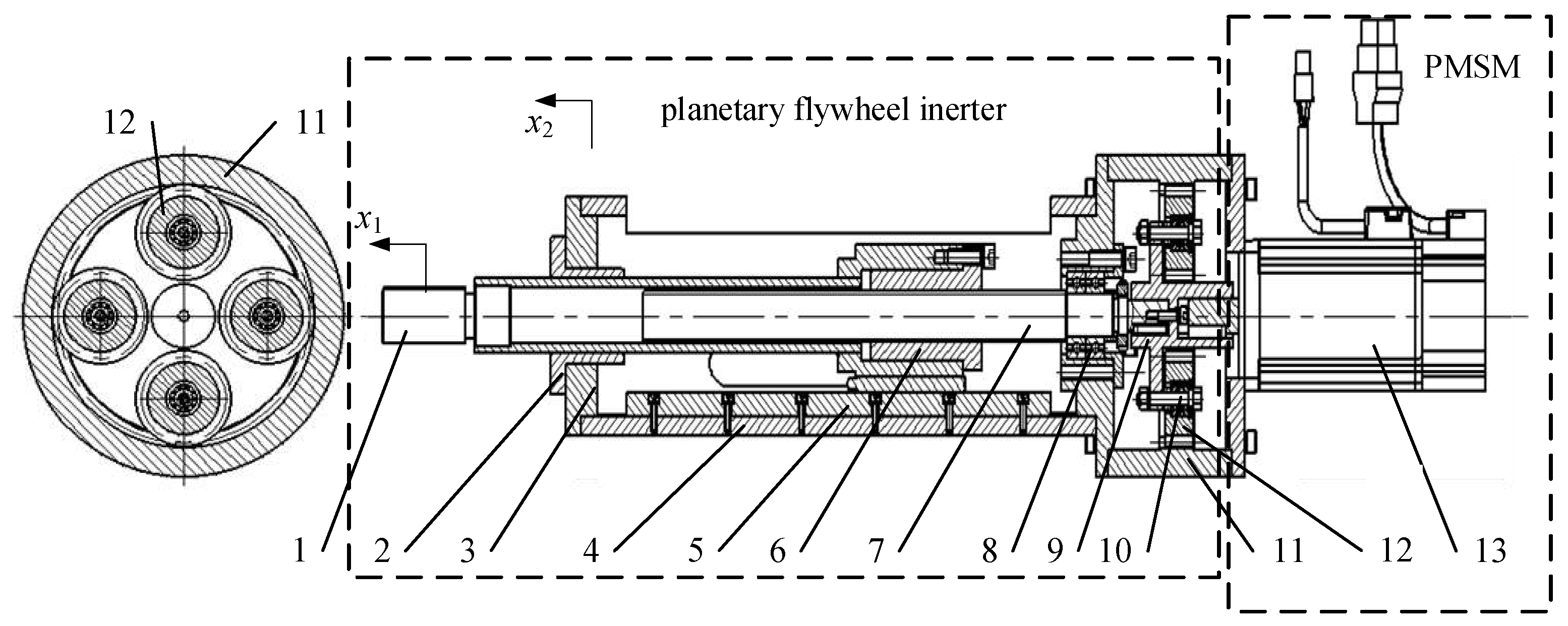
Figure 2.
Dynamic model of planetary flywheel inerter.
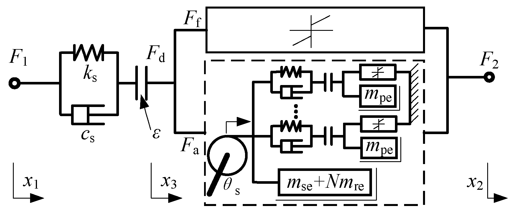
Figure 3.
Dynamic model of planetary flywheel.

Figure 4.
Dynamic model of planetary flywheel inerter actuator.

Figure 5.
Simulation model of planetary flywheel inerter actuator.
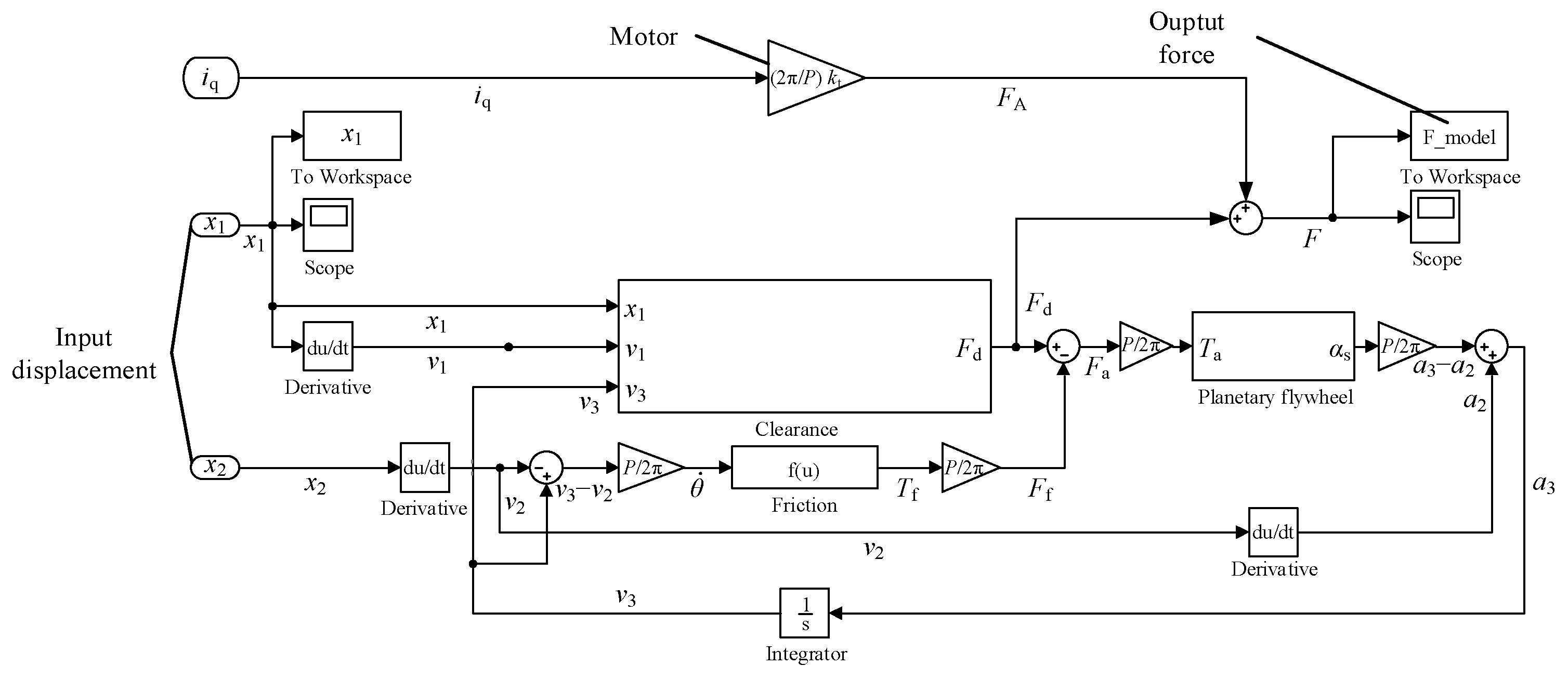
Figure 6.
Active tuned inerter damper (ATID) suspension.
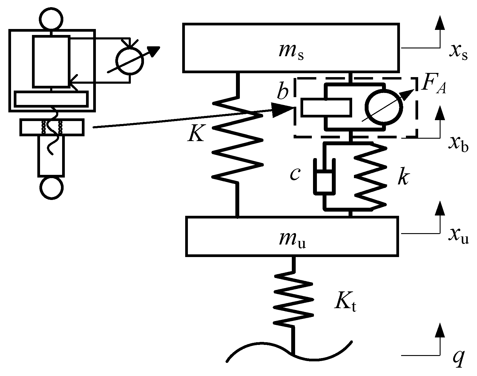
Figure 7.
ATID suspension amplitude–frequency characteristics with different inerter actuator models: (a) sprung acceleration, (b) tire load.
Figure 7.
ATID suspension amplitude–frequency characteristics with different inerter actuator models: (a) sprung acceleration, (b) tire load.
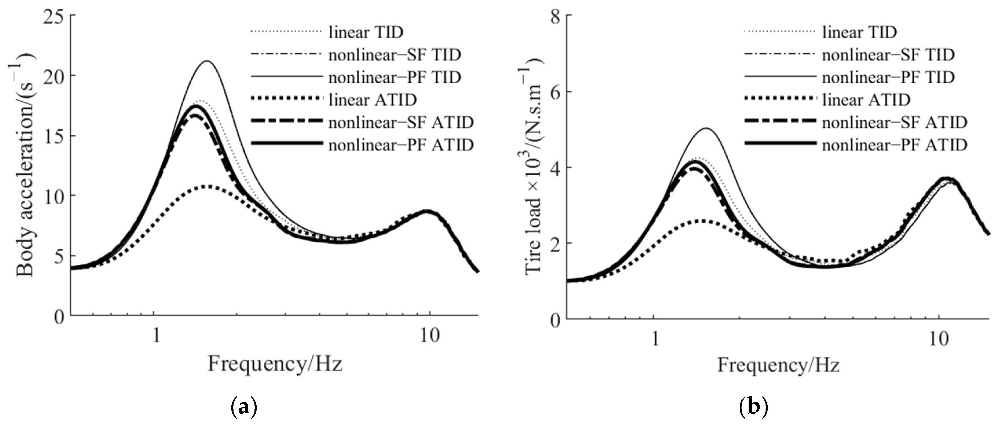
Figure 8.
The relationship between the nonlinear suspension measure to linear suspension measure ratio and the coefficient Tc.
Figure 8.
The relationship between the nonlinear suspension measure to linear suspension measure ratio and the coefficient Tc.

Figure 9.
ATID suspension amplitude–frequency characteristics with different screw–nut pair static friction torque coefficients: (a) sprung acceleration, (b) tire load.
Figure 9.
ATID suspension amplitude–frequency characteristics with different screw–nut pair static friction torque coefficients: (a) sprung acceleration, (b) tire load.
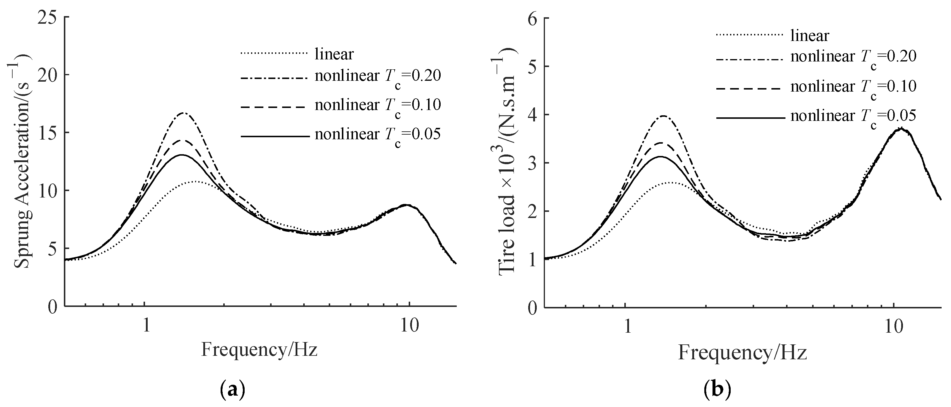
Figure 10.
The relationship between the nonlinear suspension measure to linear suspension measure ratio and the coefficient Tv.
Figure 10.
The relationship between the nonlinear suspension measure to linear suspension measure ratio and the coefficient Tv.
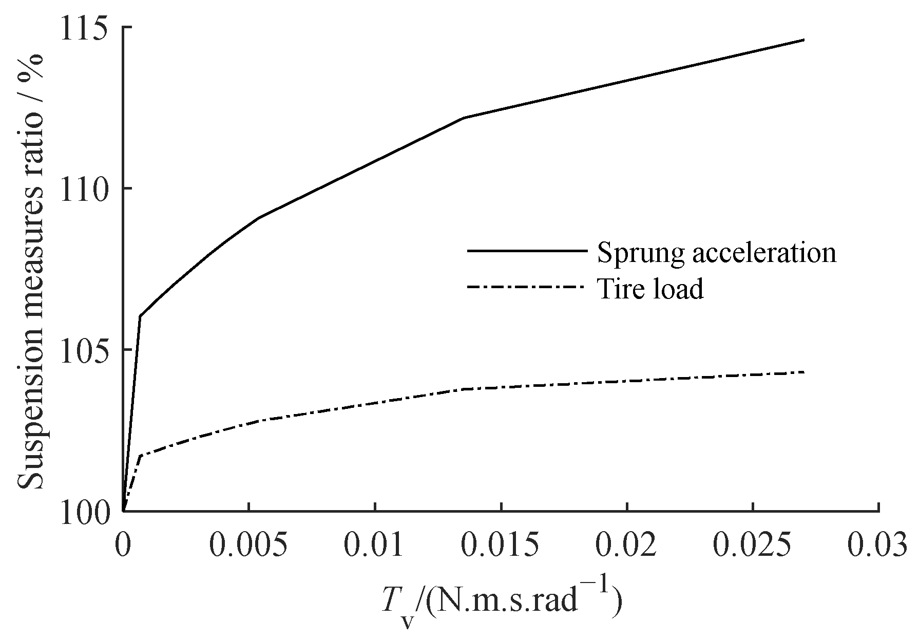
Figure 11.
ATID suspension amplitude–frequency characteristics with different screw–nut pair viscous friction torque coefficients: (a) sprung acceleration, (b) tire load.
Figure 11.
ATID suspension amplitude–frequency characteristics with different screw–nut pair viscous friction torque coefficients: (a) sprung acceleration, (b) tire load.
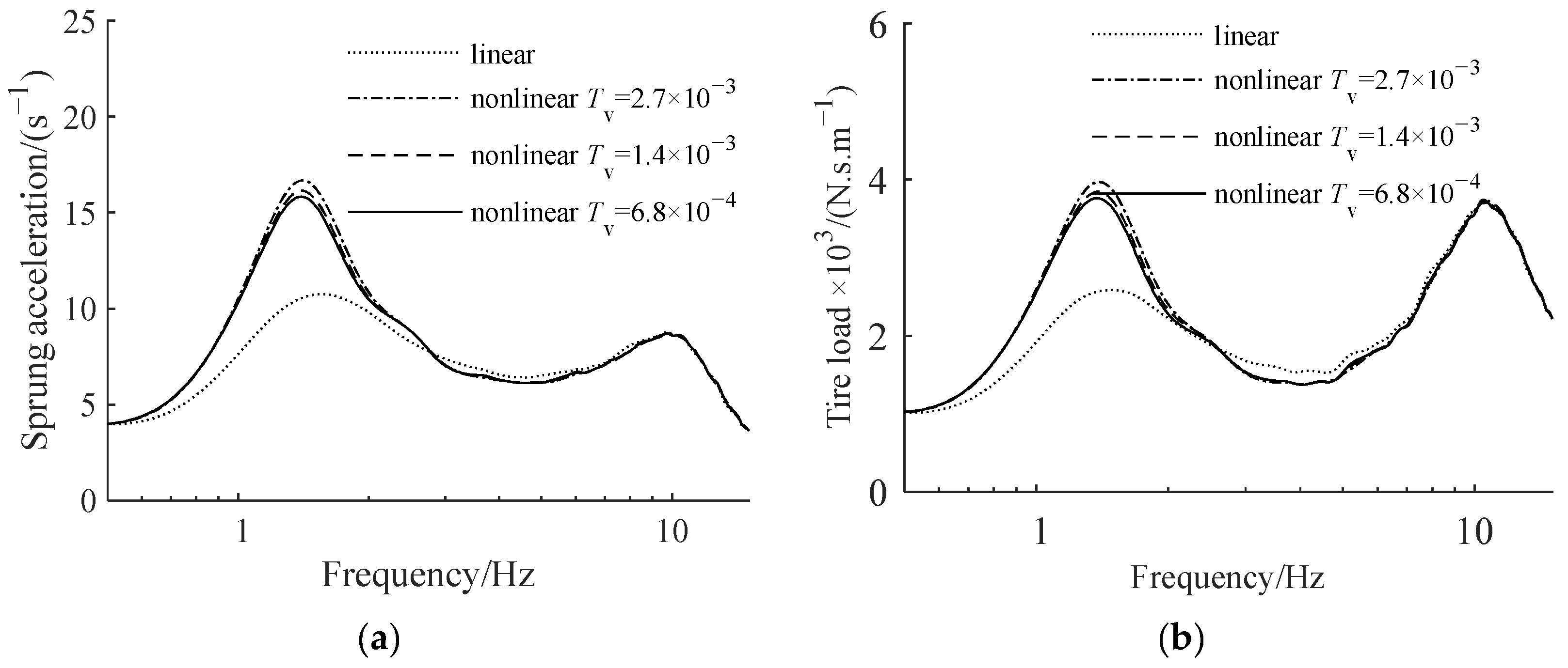
Figure 12.
The relationship between the nonlinear suspension measure to linear suspension measure ratio and the coefficient ε.
Figure 12.
The relationship between the nonlinear suspension measure to linear suspension measure ratio and the coefficient ε.
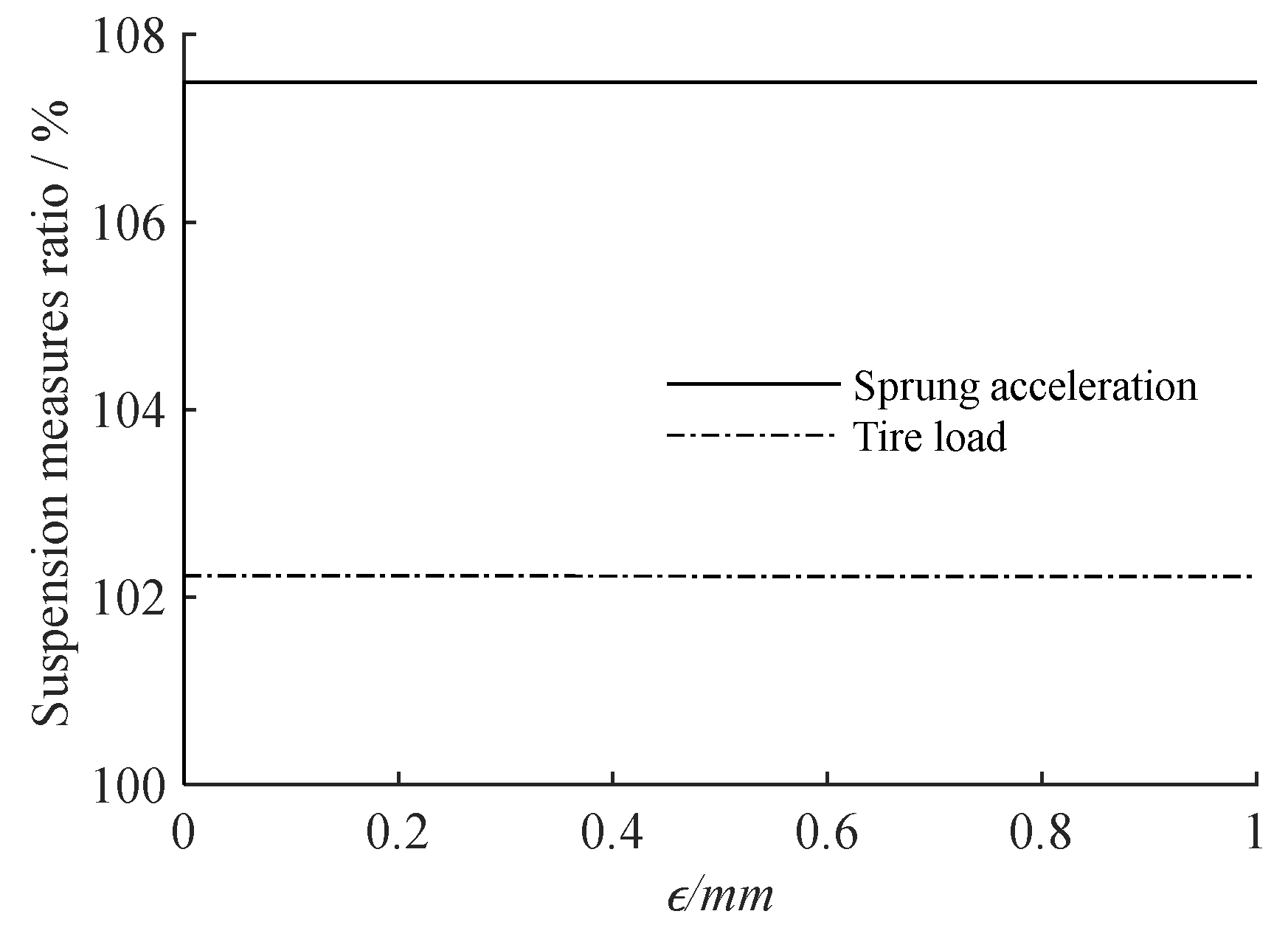
Figure 13.
ATID suspension amplitude–frequency characteristics with different screw–nut pair clearances: (a) sprung acceleration, (b) partial amplification of sprung acceleration, (c) tire load, and (d) partial amplification of tire load.
Figure 13.
ATID suspension amplitude–frequency characteristics with different screw–nut pair clearances: (a) sprung acceleration, (b) partial amplification of sprung acceleration, (c) tire load, and (d) partial amplification of tire load.
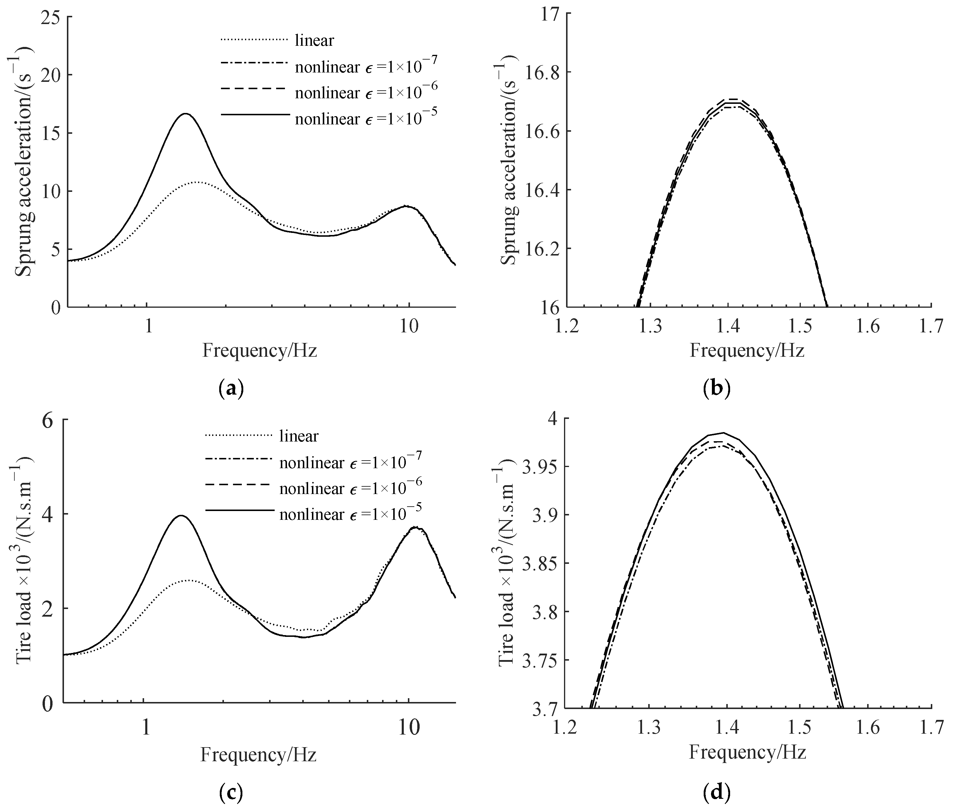
Figure 14.
The relationship between the suspension measure with planetary flywheel to suspension measure with typical single flywheel ratio and the coefficient Tfpm.
Figure 14.
The relationship between the suspension measure with planetary flywheel to suspension measure with typical single flywheel ratio and the coefficient Tfpm.
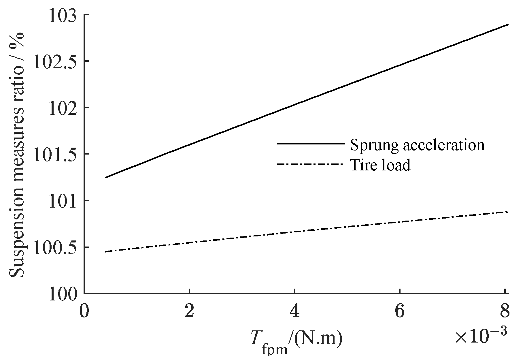
Figure 15.
ATID suspension amplitude–frequency characteristics with different planetary gears static friction torque coefficients: (a) sprung acceleration, (b) partial amplification of sprung acceleration, (c) tire load, and (d) partial amplification of tire load.
Figure 15.
ATID suspension amplitude–frequency characteristics with different planetary gears static friction torque coefficients: (a) sprung acceleration, (b) partial amplification of sprung acceleration, (c) tire load, and (d) partial amplification of tire load.
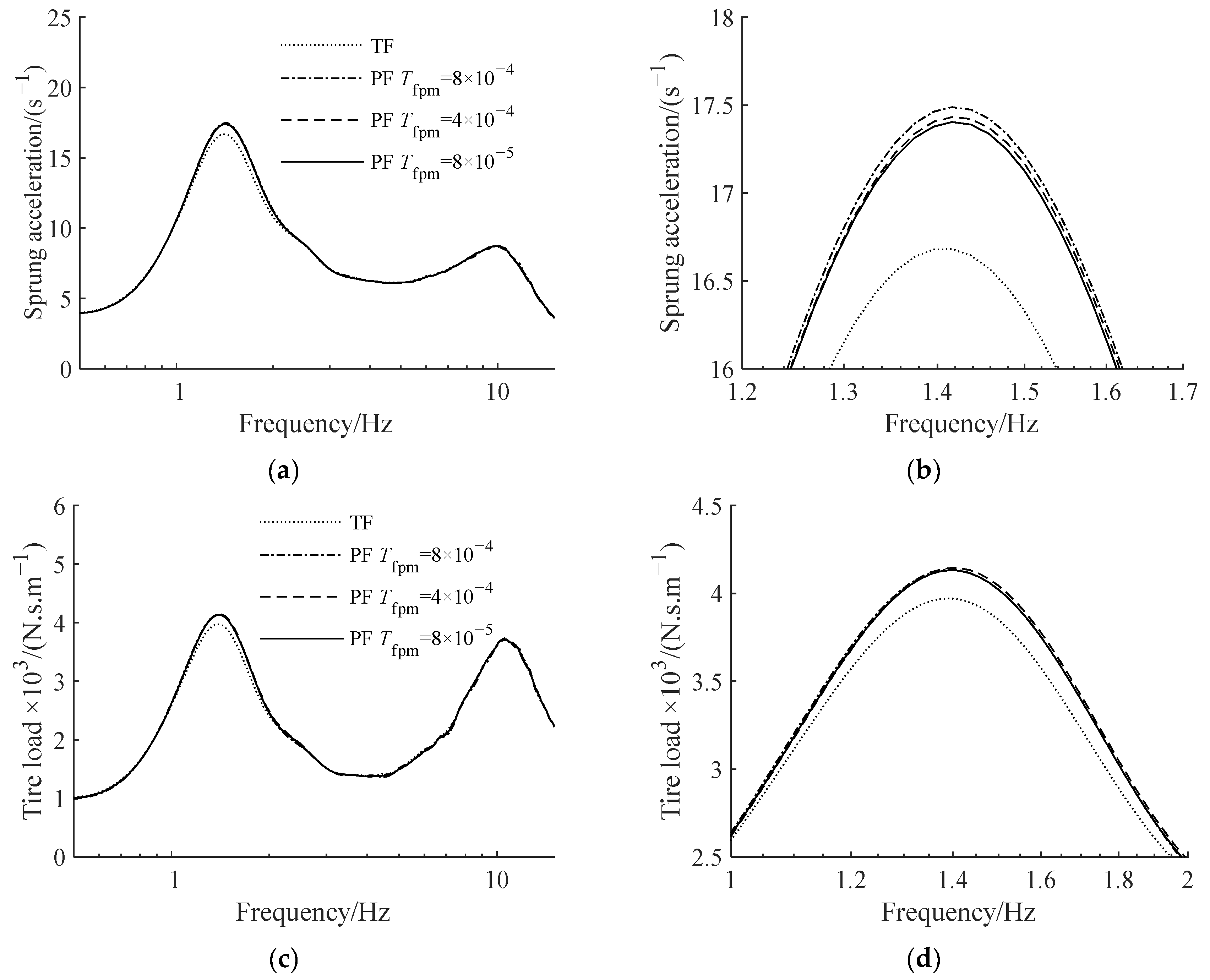
Figure 16.
The relationship between the suspension measure with planetary flywheel to suspension measure with typical single flywheel ratio and the coefficient Tfpv.
Figure 16.
The relationship between the suspension measure with planetary flywheel to suspension measure with typical single flywheel ratio and the coefficient Tfpv.
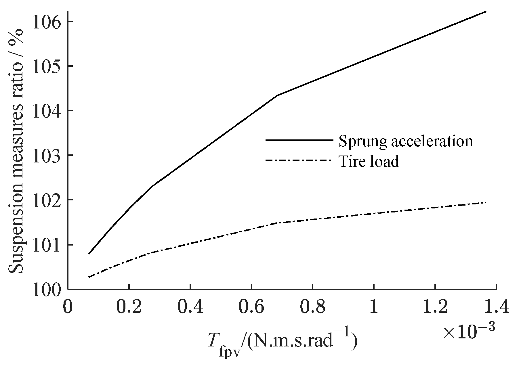
Figure 17.
ATID suspension amplitude–frequency characteristics with different planetary gear viscous friction torque coefficients: (a) sprung acceleration, (b) partial amplification of sprung acceleration, (c) tire load, (d) partial amplification of tire load.
Figure 17.
ATID suspension amplitude–frequency characteristics with different planetary gear viscous friction torque coefficients: (a) sprung acceleration, (b) partial amplification of sprung acceleration, (c) tire load, (d) partial amplification of tire load.
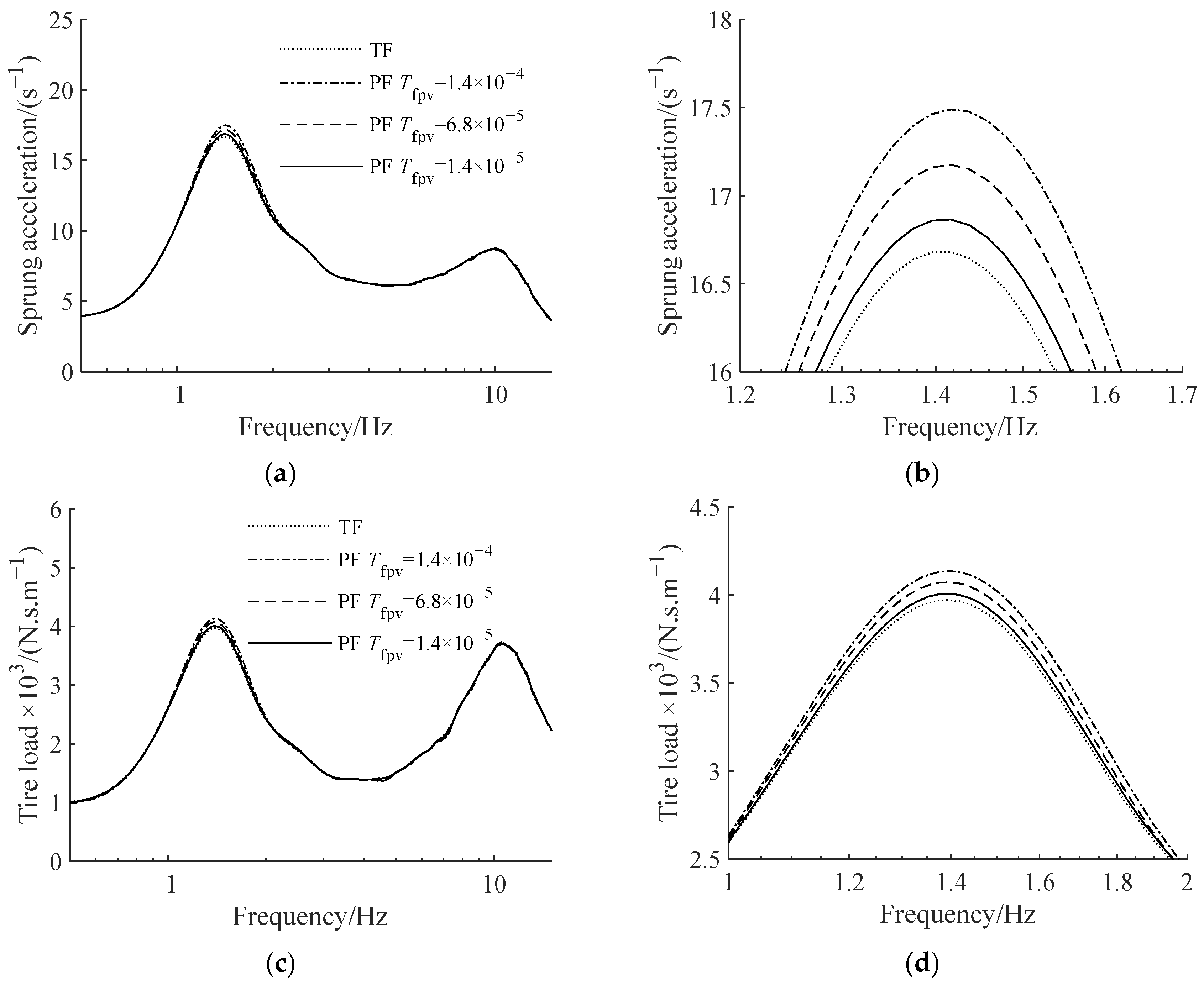
Figure 18.
The relationship between the suspension measure with planetary flywheel to suspension measure with typical single flywheel ratio and the coefficient gr.
Figure 18.
The relationship between the suspension measure with planetary flywheel to suspension measure with typical single flywheel ratio and the coefficient gr.

Figure 19.
ATID suspension amplitude–frequency characteristics with different gear backlashes: (a) sprung acceleration, (b) partial amplification of sprung acceleration, (c) tire load, (d) partial amplification of tire load.
Figure 19.
ATID suspension amplitude–frequency characteristics with different gear backlashes: (a) sprung acceleration, (b) partial amplification of sprung acceleration, (c) tire load, (d) partial amplification of tire load.

Table 1.
Basic parameters of active tuned inerter damping suspension.
| Parameter | Parameter Value |
|---|---|
| Sprung mass ms/kg | 229 |
| Unsprung mass mu/kg | 31 |
| Main spring stiffness K/(N‧m−1) | 20,213 |
| Tire stiffness Kt/(N‧m−1) | 127,976 |
| Tuned spring stiffness k/(N‧m−1) | 3304 |
| Tuned damping coefficient c/(N‧s‧m−1) | 747 |
| Inerter inertance b/kg | 385 |
| Compensation coefficient r/kg | 300 |
Table 2.
Basic parameters of planetary flywheel inerter actuator.
| Parameter | Parameter Value |
|---|---|
| Motor model | ECMA-C10604 |
| Rated power/W | 400 |
| Rated torque/(N‧m) | 1.27 |
| Rated speed/(r‧min−1) | 3000 |
| Rotor inertia/(kg‧m2) | 2.77 × 10⁻⁵ |
| Lead of screw P/mm | 10 |
| Rotation inertia of screw Js1/(kg‧m2) | 2.80 × 10⁻⁵ |
| Gear module | 2 |
| Gear pressure angle | 20° |
| Tooth number of external gear ring Z2 | 50 |
| Number of planetary gears N | 4 |
| Tooth number of planetary gear Z1 | 17 |
| Equivalent mass of planetary gear rotation mpe/kg | 7.52 × 10⁻³ |
| Equivalent mass of planetary gear revolution mre/kg | 7.22 × 10⁻² |
| Equivalent mass of planetary flywheel carrier rotation mse/kg | 2.05 × 10⁻¹ |
| Static friction torque coefficient of the screw–nut pair Tc/(N‧m) | 2.231 × 10⁻¹ |
| Viscous friction torque coefficient of the screw–nut pair Tv/(N‧m‧s‧rad−1) | 2.703 × 10⁻³ |
| Total clearance between screw–nut pair and bearing ε/m | 1.006 × 10⁻⁷ |
| Gear backlash gr/m | 1.838 × 10⁻⁶ |
| Static friction torque coefficient of the gear Tfpm/(N‧m) | 8.067 × 10⁻⁴ |
| Viscous friction coefficient of the gear Tfpv/(N‧m‧s‧rad−1) | 1.366 × 10⁻⁴ |
Disclaimer/Publisher’s Note: The statements, opinions and data contained in all publications are solely those of the individual author(s) and contributor(s) and not of MDPI and/or the editor(s). MDPI and/or the editor(s) disclaim responsibility for any injury to people or property resulting from any ideas, methods, instructions or products referred to in the content. |
© 2023 by the authors. Licensee MDPI, Basel, Switzerland. This article is an open access article distributed under the terms and conditions of the Creative Commons Attribution (CC BY) license (https://creativecommons.org/licenses/by/4.0/).
Share and Cite
MDPI and ACS Style
Ge, Z.; Li, G.; Chen, S.; Wang, W. Influence of Nonlinear Characteristics of Planetary Flywheel Inerter Actuator on Vehicle Active Suspension Performance. Actuators 2023, 12, 252. https://doi.org/10.3390/act12060252
AMA Style
Ge Z, Li G, Chen S, Wang W. Influence of Nonlinear Characteristics of Planetary Flywheel Inerter Actuator on Vehicle Active Suspension Performance. Actuators. 2023; 12(6):252. https://doi.org/10.3390/act12060252
Chicago/Turabian StyleGe, Zheng, Guangping Li, Shixiang Chen, and Weirui Wang. 2023. "Influence of Nonlinear Characteristics of Planetary Flywheel Inerter Actuator on Vehicle Active Suspension Performance" Actuators 12, no. 6: 252. https://doi.org/10.3390/act12060252
Note that from the first issue of 2016, this journal uses article numbers instead of page numbers. See further details here.