
A Review of Recent Developments in Permanent Magnet Eddy Current Couplers Technology
by
 ,
,
Jiaxing Wang
1,
Dazhi Wang
1,*,
Sihan Wang
1,
Tailai Tong
1,
Lisong Sun
1,
Wenhui Li
1,
Deshan Kong
1,
Zhong Hua
1 and
Guofeng Sun
2 1
College of Information Science and Engineering, Northeastern University, Shenyang 110819, China
2
Yantai State Grid, Yantai 264001, China
*
Author to whom correspondence should be addressed.
Actuators 2023, 12(7), 277; https://doi.org/10.3390/act12070277
Submission received: 2 June 2023
/
Revised: 26 June 2023
/
Accepted: 3 July 2023
/
Published: 7 July 2023
(This article belongs to the Section High Torque/Power Density Actuators)
Abstract
:Permanent magnet eddy current couplers (PMECCs) have the characteristics of contactless torque transmission, removal of torque ripple, smooth dynamic process, and adjustable speed, and can be used as couplings, dampers, brakes, and speed governors. Their applications in industry, vehicles, and energy fields are gradually expanding. At the same time, the requirements for the torque density and dynamic performance of PMECCs are increasing. Therefore, a large amount of research work has focused on the fast and accurate modeling, design, and optimization of PMECCs. This paper provides a survey on the development of PMECCs technology. The main topics include the structure and classification of PMECCs, modeling methods, loss and heat transfer analysis modeling, and optimization design. In addition, this paper shows the future trends of PMECCs research. All the highlighted insights and suggestions of this review will hopefully lead to increasing efforts toward the model’s construction and the optimal design of PMECCs for future applications.
1. Introduction
PMECCs use an electromagnetic field as the medium of power transmission, and have the characteristics of contactless torque transmission, removal of torque ripple, smooth dynamic process, and adjustable speed, and can be used as couplings, dampers, brakes, and speed governors. Over the past few decades, both academia and industry have witnessed the rapid development of PMECCs, which have been widely used for high-efficiency, adjustable, speed power transmission [1], non-contact braking [2,3,4], vibration absorption and damping [5,6,7,8,9], the removal of cogging torque and torque ripple in wind turbines [10,11,12,13,14,15], automotive variable flow water pumps [16], the torque-speed characteristic measurement of electric motors or vehicles [17,18], and even in vehicles as a mechanical differential [19].
The basic structure of PMECCs is shown in Figure 1; usually with a permanent magnet (PM) rotor on one side and a conductor rotor on the other side, the PM and the conductor are mounted separately on the back iron, and the two transfer mechanical energy through non-contact rotation [20,21]. The PMECCs are mainly divided into two types of axial flux (also known as disk or plate PMECCs) and radial flux (also known as barrel or cylinder PMECCs) from the structure [22,23], and there are also some special structural designs with adjustable flux [24,25,26,27,28,29].
The PMECCs transmit torque by creating a magnetic field through the eddy currents induced in the conductor rotor, and generate a large amount of heat while transmitting torque [30,31,32,33,34]. In particular, when used as a braking device, the heat of the device will cause the temperature to rise severely, which may lead to the permanent demagnetization of the PM; so, it is necessary to model the thermal field to facilitate the design of heat dissipation [35,36,37]. Therefore, the study of PMECCs is a typical multi-field coupling problem. Thus, there are large amounts of references focusing on electromagnetic field (EMF) modeling, thermal analysis, and the optimal design of PMECCs.
Modeling and optimal design is a key issue in the development of and scientific research on PMECC [32,38,39,40,41]. The process of modeling is used to solve the distribution of the magnetic field and eddy current by establishing the electromagnetic field model and the thermal model of the corresponding mechanical structure, and then to calculate the output of torque to evaluate the performance of the PMECC. The optimal design based on the existing model is used to find the optimal configuration for the required performance, to improve the efficiency of the device, to reduce the material cost, and to reduce the rotational inertia [42].
In this paper, rotating eddy current couplers (also known as break, drive, damper, or retarder) with PM excitation are studied. There are many improved types of devices using the same operating principle, such as those with linear motion [43,44,45], those using electrical excitation [46,47,48,49] and hybrid excitation [50], and high-temperature superconducting materials that make PMs to enhance magnetic fields [51]. On the conductor rotor side, superconducting materials [48,52,53,54,55], ferromagnetic materials [56,57], and PMs [58,59,60,61,62,63,64,65] on the conductor disk side are used. These structures are out of the scope of this paper.
This paper presents a comprehensive reference study of articles on PMECC from recent years. The articles are organized as follows. Section 2 describes the operating principle, structure, and classification of PMECC. Section 3 discusses the numerical and analytical modeling methods of PMECCs. Section 4 reviews the loss calculation and thermal analysis of V. Section 5 emphasizes the optimal design of PMECC. Section 6 concludes the whole paper and gives future research directions for PMECC.
2. Working Principle, Structure, and Classification of PMECCs
In terms of mechanical structure, PMECCs can be divided into axial flux type and radial flux type. For both axial and radial type, the important part of the PMECC is composed of a PM rotor and a conductor rotor, which are not in mechanical contact with each other and are connected to the motor and the load, respectively. The basic structures of the two types are shown in Figure 1; the PM rotor part consists of PM and back iron, and the conductor rotor part consists of conductor disk (disc) and back iron. PMs are usually selected from rare earth magnets such as Nd2Fe14B, which have a high maximum energy production and high coercivity. The back iron adopts a ferromagnetic material with high permeability, e.g., 20 steel (Chinese standard) [66], M-27 steel [67], steel 1010 [68], which facilitates the establishment of a stronger magnetic field in the air gap. It is well known that the permeability of ferromagnetic materials has nonlinear characteristics; in other words, ferromagnetic materials have magnetic saturation. In the available references, some studies are limited to the study of the linear permeability part of ferromagnetic materials, while some consider the nonlinear characteristics of materials to be described by the B–H curves of materials, as shown in Figure 2 for the B–H curves of ferromagnetic materials used in the PMECC. The PMECCs work by transferring torque from the motor side to the load side through the air gap, with no connection between the drive side and the load side of the device. The torque is generated by the interaction between the strong rare-earth PMs located on one side of the drive and the induced current generated by the relative motion of the conductors located on the other side. A precise control of torque can be achieved by varying the air gap length, which results in speed control.
PMECCs used as speed governors and brakes usually contain adjustable mechanisms. An adjustable PMECC generally consists of three parts: one is the PM rotor connected to the load; the second is the conductor rotor connected to the motor, which has a certain air gap between the two rotating components; the third is an actuator, through which the length of the air gap between the two rotating components is adjusted to adjust the output torque to achieve the control of the load output speed. Figure 3a is the actual structure diagram of the adjustable speed PMECC with an actuator and heat sink. Figure 3b shows the structure schematic of Figure 3a. The speed-adjustable PMECC is used to achieve speed control by adjusting the torque. The torque output from the motor to the speed-adjustable PMECC and the torque output from the speed-adjustable PMECC to the load are equal. In this way, we can adjust the torque at the output of the motor according to the amount of torque during the actual operation of the load.
According to the mechanical structure, the PMECCs contain two main basic types of axial flux and radial flux, in addition to the composite structure that combines both structures. According to the mounting method of PMs, there are also surface-mounted and surface-inset types. Reference [1] conducted a comparative study on PMECCs with different topological structures. On the basis of these basic structures, some new and improved structures have been developed by optimizing the design of the conductor disk for slotting or grooving, PM shape, or magnetization direction, as described below.
2.1. Axial-Flux PMECCs
Axial-flux PMECCs are characterized by a small axial length, large center height, large rotational inertia, and low alignment requirements. A single-sided structure (consisting of a PM rotor and a conductor rotor) also has the problem of large axial forces, although a symmetrical bilateral structure has been used in product design to offset the effects of axial forces on the input and output shafts [70].
According to the mounting and magnetization mode of PMs on the PM rotor, as shown in Figure 4, they can be divided into surface-mounted (Figure 4a) and surface-inset (Figure 4b), where the PMs of the surface-mounted structure are mostly in a vertical magnetization mode, while the PMs of the surface-inset structure are mostly in a horizontal magnetization mode, and the surface-inset structure is also called the flux-focusing type [71,72]. Both surface-mounted and surface-inset, the conventional axial-flux PMECCs achieve the adjustment of the transferred torque by adjusting the length of the air gap between the conductor rotor and the PM rotor.
2.1.1. Surface-Mounted
References [22,23,32,67,73,74,75,76,77,78,79,80,81] all present conventional surface-mounted PMECCs. Their basic structure is shown in Figure 4a, and researchers have conducted a lot of modeling studies for this structure, and the PMECCs in the references are all single-disk structures with sector-shaped Nd2Fe14B PMs. The surface-mounted structure is simple and the magnetic pole arrangement is flexible.
In order to counteract the axial force of the single-side structure and increase the torque at the same time, references [66,82,83,84,85,86] used a double-disk structure. In references [82,83,84,85,86], the conductor disk was in the middle and the PMs were on both sides. Its structure is shown in Figure 5a, N and S poles are arranged alternately and the N pole is opposite to the S pole across the conductor disk. Reference [66] presented PMs in the middle with conductor disks on both sides. Its structure is shown in Figure 5b. Reference [31] presented two unilateral structures combined to counteract the axial force.
2.1.2. Surface-Inset
References [71,87] presented an axial flux surface-inset PMECC, which uses a lower cost rectangular PM and consists of a PM rotor and a conductor disk rotor, as shown in Figure 6a. The arrows indicate the direction of magnetization of the magnetic poles. References [72,88] presented a flux-focusing PMECC with double-slotted conductor rotors, which uses a double-side structure, and which has one PM rotor and two conductor rotors, as shown in Figure 6b. In the PM rotor, red and green indicate PMs with different magnetization directions. Both have the same PM structure, which is inset in the core and magnetized in the direction of the circumference.
2.2. Radial-Flux PMECCs
The radial flux type is characterized by small rotational inertia, high torque density, and a low requirement for center height and no axial force, but the axial dimension is larger and the corresponding shaft alignment accuracy requirement is higher than that of the axial-flux PMECC. There are two types of radial-flux PMECC displayed in Figure 7, surface-mounted and surface-inset, respectively.
2.2.1. Surface-Mounted
The structure of the surface-mounted radial-flux PMECC is shown in Figure 1b and Figure 7a. A surface-mounted radial-flux PMECC with internal PMs and an external conductor rotor was proposed in references [89,90,91,92,93,94,95,96,97]. A radial-flux PMECC with an internal conductor rotor and an external PM structure was proposed in references [98,99,100]. The bilateral structure, as shown in Figure 8, also appears for the radial flux type since it can also effectively increase the torque [11,12,101,102,103].
2.2.2. Surface-Inset
A flux-concentration cage-type PMECC with a slotted conductor rotor topology was proposed in references [104,105], and the 2D geometry of the studied PMECC is shown in Figure 9. The PM rotor is inside the conductor rotor; each PM is magnetized along the circumference and inset in the core. Different colors and arrows in the figure indicate different magnetization directions of the PMs.
2.3. Novel Design Topologies of PMECCs
PMECC are widely used because of their simple structure. In recent years, researchers have been innovating their design to increase torque density, improve efficiency, reduce size, reduce rotational inertia, and make torque regulation more flexible. For the innovative design of PMECCs, the parts involve the topology, PM, conductor, and regulating device. The improvement in the topology involves a combination of axial and radial structure. The goal of the improvement in the PM is to increase the flux density of the air gap and to obtain a more desirable sinusoidal distribution of the magnetic field. The slotting of the conductor rotor allows for a larger circuit of eddy currents and a certain range of increased torque. The new flux-adjustable mechanism is able to adapt to more complex scenarios. A detailed description is given below.
2.3.1. Axial–Radial Combined PMECCs
A topology combining axial flux and radial flux has been proposed in references [34,106,107,108,109]. The combination of a traditional axial-flux PMECC and a radial-flux PMECC not only makes it possible to increase the area of the induced magnetic field, but also to magnetize it in both axial and radial directions, improving the corresponding transmission efficiency. The structure proposed in references [34,106,107,108] consists of a conventional radial-flux PMECC and a double-sided axial-flux PMECC, which is used for coupling in a scraper conveyor, working under bad conditions including overload startup, severe abrasion, and pollution, as shown in Figure 10a. The structures proposed in reference [109] can be used to obtain a load speed that can be controlled and regulated by adjusting the relative positions of the two rotors, as shown in Figure 10b. In Figure 10a,b, N and S indicate the direction of magnetization of the PMs.
2.3.2. Novel Magnetization Method
A Halbach array is a combination of PMs with different magnetization directions in a certain order so that the magnetic field of one side of the PM is significantly enhanced while the other side is significantly weakened, and it is easy to obtain a more ideal sinusoidal distribution of the magnetic field. Halbach arrays are widely used in PM motors, magnetic levitation technology, linear motors, magnetic bearings, and other fields because of their unilateral magnetization effect, which can significantly enhance the air gap magnetic density of magnetic functional devices and improve the utilization of PM materials [110].
In references [69,111,112,113], Halbach arrays were applied to axial-flux PMECCs. The authors of [89,90,97,114] applied Halbach arrays to radial-flux PMECCs. A four-layer field model of the quasi-Halbach PMECC is shown in Figure 11. It is worth mentioning that the authors of [115] improved the torque output of the axial-flux PMECC by constructing a magnetic field with injected harmonics in the air gap through the PM shape design.
2.3.3. Slotted Conductor Rotor
Slotted conductor rotors can force eddy currents to flow perpendicular to both the magnetic field line and the rotation axis, and the use of back-iron filled slots can enhance the air-gap flux density, and the Lorentz force and transmitted torque are consequently optimized. To improve the efficiency and torque density, the first study of slotted conductor disks was conducted in 2006 by [116], and the number and size of the slots and the effect of using back-iron filling on the performance were investigated. Subsequently, references [66,70,72,82,117,118,119] studied the axial-flux PMECC, as shown in Figure 12. Red and blue indicate PMs with different magnetization directions. References [98,100,104] also extended the study of slotted structures to radial fluxes. In addition, the authors of [120,121] studied the different grooves on the surface of the conductor, and compared the effects of the different shapes of grooves on the braking torque and the change in magnetic flux by using the method of finite element analysis (FEA). The general conclusion can be obtained that the slotted conductor disk can significantly increase the torque transferred by the PMECC, or the braking torque of the brake in a certain speed range.
2.3.4. Novel Flux Adjustable PMECCs
Conventional axial-flux PMECCs adjust the torque by adjusting the air gap distance between the PM rotor and the conductor disk rotor. For radial-flux PMECCs, the torque is adjusted by adjusting the distance between the two moving rotors and changing the relative area between the PM rotor and the conductor rotor. Based on the basic structure, many new regulating mechanisms have been proposed. The authors of [122] proposed a PM rotor consisting of three parts; the inner, middle, and outer parts of the PM rotor can be adjusted to achieve the output torque adjustment by adjusting the middle PM. This structure can simplify the adjustment mechanism of the PMECC and reduce the size of the PMECC, as shown in Figure 13a. The Figure 13a shows the structure of the PMECC using different views. Red and blue indicate PMs with different magnetization directions. Reference [123] has a similar structure to reference [122], with the difference being that a double-side conductor disk structure is established, as shown in Figure 13b. A new axial-flux adjustable PMECC with a movable stator ring is proposed in reference [27]. The slip speed of the proposed PMECC can be adjusted by shifting the axial position of the movable stator ring. In order to improve the torque density and simplify the actuator of a conventional speed-adjustable PMECC, a new squirrel-cage rotor PM adjustable speed drive with a non-rotating mechanical flux regulator is proposed in reference [24]. A new flux-adjustable PMECC with multiple rotors is proposed in reference [124]. According to the different functions, the PM rotors can be divided into rotors with fixed flux and adjustable flux. By adjusting the relative positions of the two types of PM rotors, the magnetic field, torque, and output speed can be controlled without changing the air gap distance.
3. Modeling Methods for PMECC
For rotating electromagnetic devices, an analysis of their air-gap magnetic field and torque characteristics helps to predict the performance of the device and optimize it later, and the development of new topologies of devices is based on familiarity with their magnetic field and torque characteristics. The rotating eddy currents on the rotor of the PMECC conductor increase the difficulty of solving its magnetic field and torque characteristics. Thanks to existing methods for solving the eddy current and magnetic field problems of moving conductors, accurate electromagnetic field modeling is the basis for subsequent optimal design. There is a large number of modeling studies for PMECCs with different topologies, structures, and operating conditions. These methods can be basically divided into two categories, numerical and analytical methods.
3.1. Numerical Methods
Generally speaking, the numerical methods for electromagnetic field research mainly include the finite difference method, finite element method (FEM, also known as finite element analysis (FEA)), integral equation method, boundary element method, etc. In the study of PMECC, most scholars choose existing finite element calculation software such as ANSYS, Comsol, JMAG-Designer, Altair Flux, etc., for two-dimensional (2D) or three-dimensional (3D) electromagnetic field calculation. The finite element software-based method is applicable to any topology and is a general solution method with a relatively mature technology, and usually the FEM is also used as a validation tool for the analytical method.
The most promising and popular numerical method is FEM. In FEM, the analysis domain is divided into subdomains through a mesh, and each subdomain becomes a simple and small part called a finite element. Each element has an appropriate approximate solution, and the solution of the domain satisfying the structural equilibrium condition is derived. Dirichlet, Neumann, and periodic boundary conditions are used to solve FEA problems. A detailed description can be found in reference [125] Section 1.2 “Numerical Solution”. The definition and allocation of finite elements are flexible, making FEM applicable to any complex device topology structure and providing an accurate performance solution, such as the magnetic field distribution in any component. The computational burden is the main limitation of FEM because it requires the meshing of the entire solution domain. With the improvement in computational power, this problem has gradually been addressed, making FEM the most commonly used tool. Currently, in the study of PMECCs, FEM can be mainly divided into 2D FEM and 3D FEM.
A new flux-adjustable PMECC with a double-layered PM rotor is proposed in reference [29]. Using the 2D FEM, the torque and magnetic field, each at different relative position of PM rotors, are analyzed, and the magnetic field distribution and air gap flux density at each relative position are analyzed in the static field; the torque and speed curves are calculated in the transient field, and the effects of structural parameters on the torque are analyzed and calculated based on the torque–speed characteristics, which provides a reference for the structural optimization design of this PMECC. Reference [116] was the first to study slotted conductor disks. In order to analyze the performance of the PMECC and compare it with general designs, a 2D FEA model was developed. Various slotted designs, the influence of the number and size of the slots, and the effect of filling slots with iron were studied based on this model.
The authors of [126], in 2006, performed a 3D FEM of a PMECC based on a 2D FEM model. The 3D effects of the geometric structure and the nonlinearity of the materials were considered, and it was concluded that calculations were usually difficult when the material was highly saturated due to the level of FEM technology at the time. In reference [13], transient simulation studies of the eddy current of a PMECC were conducted using 2D and 3D FEM, respectively, and the two FEM results were compared, and the results showed that the 3D FEM is more accurate than the 2D FEM.
Reference [92] developed a FEA model of a water-cooled PMECC considering the characteristics of the PM and the thermal conductivity of the material. The distribution of eddy currents and temperature was analyzed using a magneto-thermal coupling method. The results showed good consistency between the 3D FEM simulation results of temperature and braking torque and the experimental test results. Reference [127] proposed a modeling technique for axial-flux PMECCs based on a vector J-A hysteresis model. The parameters of the J-A hysteresis model were obtained using a fast identification method based on numerical methods and genetic algorithms (GAs), and the model was applied to numerical calculations to improve the convergence and reduce the calculation time. Reference [13] conducted transient simulation studies on the eddy currents in a PMECC using both 2D and 3D FEM, and compared the results of the two methods. The results showed that 3D FEM was more accurate than 2D FEM.
It can be seen from the analysis that these methods can simulate the actual working conditions of the research objects and obtain extremely accurate analysis results. The disadvantage is that it requires precise meshing, and the computation is very large, requiring expensive computer hardware; so, it is not suitable for the initial design process of devices, but is often used as a verification tool.
3.2. Analytical Methods
Compared with numerical methods, analytical methods can significantly reduce the computational workload, but, in the process of analytical modeling, a large number of idealized assumptions are often required, sacrificing some accuracy. Analytical modeling methods can intuitively study the influence of geometric parameters or material properties on the final performance of the PMECC, which is very important in the pre-design stage of the PMECC. For research on PMECCs, analytical methods can be divided into equivalent circuit methods and layer model methods based on Maxwell’s equations.
3.2.1. Magnetic Equivalent Circuit Method
The magnetic equivalent circuit (MEC) method is a widely used and simple magnetic field analysis method in electromagnetic device design and optimization. Its basic idea is to transform the abstract magnetic field problem into a mature electric field problem. Based on principles such as consistent material properties, similar cross-sectional areas, and the same magnetic flux passing through the cross-sectional area, the system’s magnetic field is divided into different magnetic circuits. By combining Kirchhoff’s law and Ampere’s law, equations related to magnetic flux are obtained. For complex magnetic circuit structures, such as those that require a consideration of the magnetic circuit of a double-sided PMECC, the complex magnetic field magnetic circuit needs to be divided into multiple magnetic branches with magnetic resistance or magnetic potential. These branches are connected in parallel or series to form a network, thereby simplifying the problem, which is known as the equivalent magnetic network (EMN) method.
Regarding the research on PMECCs, the MEC method can be divided into 2D and 3D MEC methods. Although the 3D MEC method can consider the radial leakage of the PM, due to the complexity of the 3D MEC method model, most scholars mainly focus on the 2D MEC method. The 2D MEC method expands the PMECC along the circumferential direction at the average radius and analyzes the magnetic flux path of the PMECC on this 2D model.
In reference [78], a flux-tube model is established considering the three-dimensional structure and radial leakage of the PMECC. The 3D MEC method can handle complex geometric structures and consider all geometric parameters and material properties, such as iron saturation and the non-linear characteristics of the PM.
In the research on the 2D MEC method of the PMECC, the eddy current generated in the conductor sheet poses a difficulty for model establishment. Currently, there are three main methods used to deal with the problem of eddy current generation in the eddy current region. The first method is not to consider the eddy current reaction field in the MEC but to directly solve the air gap magnetic field based on the static MEC model. Then, based on Faraday’s law, the induced current generated by the moving conductor disk in the magnetic field is solved, and the magnetic field generated by the eddy current is calculated using Ampere’s law. Differential equations are then written and solved to calculate the eddy current in the conductor disk, and then the eddy current loss power is calculated to solve the torque. Typically, the Russell–Norsworthy correction factor is used to convert 2D results to 3D results [128]. Reference [129] shows the simplest application of this method. The calculation process is shown in Figure 14, which is the following functional block diagram. In the block diagram, red indicates physical quantities and blue indicates laws of physics.
The first MEC method is the basic method for modeling PMECCs, and there are many in-depth studies and innovative applications based on this method.
The in-depth study focuses on the nonlinearity of the material in the model, the skin effect of eddy currents, and the effect of heat generation on the electromagnetic characteristics. Reference [130] developed an accurate and simple performance prediction model by considering the saturation of the ferromagnetic material, the operating temperature, and the electromagnetic effects of the back iron. Reference [76] considered the skin effect of eddy currents based on the existing MEC model and the thermal effect of eddy currents, and developed a thermal network model to solve for the temperature distribution, considering the effect of temperature on resistivity and residual flux density. Reference [75] solved for the torque under a 2D model using the MEC method, and also solved the air-gap flux density and compared it with the FEM to verify its accuracy, and also considered the aggregation effect of the sector PM on the eddy currents and introduced the corresponding correction coefficients. Reference [31] investigated, in depth, the electromagnetic and thermal nonlinearities of the material, such as the thermal effects on magnetic properties, skin effects, and the inductive resistance of eddy currents. On the basis of the magnetic circuit analysis, the relationship between sensitive parameters and transmission performance is summarized in Figure 15. Based on the MEC method, Faraday’s law, and the lumped parameter thermal network method, the analytical model of PMECC including all sensitive parameters and electromagnetic and thermal nonlinearities was established. MF is the magnetic field, EF is the eddy current field, TF is the temperature field, A is the skin effect, B is eddy current induced reactance, C is thermal effect of conductivity, D is the thermal effectof reluctance; E is the thermal effect of PM, F is saturation effect.
The innovative applications are mainly the application of the first MEC to new topologies, new structures, etc. References [108,109] used this MEC method to model the combined axial and radial PMECCs and investigated the performance of the new topology. Reference [131] analytically modeled four typical PMECCs consisting of surface-mounted and interior PMs, slotted and non-slotted conductor rotors based on the MEC method, and the basic electromagnetic characteristics of PMECCs were investigated using the developed analytical models. In reference [84], the model was applied to the optimal design of the axial-flux PMECC with double-side PMs for dynamic applications, and the flux, flux density, and torque were solved using an iterative method, considering the nonlinear B–H curve based on the original method. References [88,132] applied the method to a PMECC with a two-side conductor rotor, both considering nonlinear B–H curves and using an iterative method to solve for the magnetic permeability. Among them, reference [132] considered the difference in the inductance characteristics of a copper disk rotor at different slip frequencies, proposed the concept of effective permeability of a copper disk rotor, established the equivalent permeability calculation model of a copper disk rotor at a different slip, and improved the accuracy of the model in the range of increased slip. Reference [122] applied the first MEC method to a new flux-adjustable axial-flux PMECC for its performance study. Reference [71] applied the first MEC method to an axial-flux surface-inset PMECC, considering material properties such as the saturation of the iron and the properties of the PM. In the same way, the team also modeled a radial-flux PMECC [95].
The second MEC method is to model the region where eddy current loops are formed in the conductive rotor of the PMECC as a coil winding, and to establish an equivalent circuit model similar to that of an induction motor. As shown in Figure 16, the authors of [68] used an analytical magnetic field solution for a copper disk as a basis to equivalently represent the region where eddy current loops are formed in the conductive rotor of the PMECC as a coil winding, and established an equivalent circuit model similar to that of an induction motor. In Figure 16, the volume element can be seen as a coil, which is characterized by inductance and resistance. is the electromotive force which is induced by the change in , is the equivalent resistance, and is the equivalent inductance. The authors then applied this model to analyze the performance of an axial-flux PMECC [133].
The third MEC method involves introducing a branch magnetic circuit that considers magnetic dynamics and reaction flux in the constructed MEC, where eddy current effects are inherently considered. In other words, a branch magnetic circuit with eddy current resistance is introduced into the MEC model, where eddy currents are treated as magnetic potential. A typical reference that uses this method is [23], which establishes an MEC model for an axial-flux PMECC. Reference [134] analyzes the torque characteristics of a slotted PMECC using a similar method, considering the modulation of the magnetic field and eddy current by the iron teeth in the conductor disk. The final results show that this method is accurate and effective at low slip speeds and short air gaps. Reference [135] proposed a PM rotating-type axial magnetic flux PMECC and used this method to establish an MEC model when the PM and conductor disk are not parallel. In the case of a low slip speed, short air gap, and thin conductor disk, the results obtained from this model are consistent with those obtained from the FEM. Reference [136] considers the skin effect of eddy currents based on this method to improve the accuracy of torque calculation.
3.2.2. Analytic Modeling Method Based on Maxwell’s Equations
The method typically used for this model is the separation of variables (SoV) method, also known as the layer model method, which is an electromagnetic field solving method with advantages and disadvantages compared to numerical analysis methods and MEC methods. According to the consistency of material properties, this method divides the study object into different regions and establishes the control equations for each region, generally Poisson’s equation, Laplace’s equation, and the diffusion equation. These partial differential equations are solved by the separation of variables method, and unknown constants in the general solution are determined based on boundary conditions. This method is the focus of research of many scholars both domestically and internationally and plays an important role in the analytical modeling and analysis of the magnetic field, eddy current field, and the torque performance of PMECCs.
Depending on the coordinate system chosen for modeling, the model can be divided into Cartesian coordinates (rectangular coordinates) and cylindrical coordinates. In the Cartesian coordinate system, the overall cylindrical device is cut along the average radius and is flattened along the circumferential direction. The equivalent model of the linear geometric structure exhibits periodic symmetrical distribution in the x-axis direction, and the actual x-axis length depends on the number of pole pairs. Usually, a pair of magnetic poles is selected for modeling and research, and the results of the entire structure are obtained through the number of pole pairs. The model established in the Cartesian coordinate system will cause curvature effects problems, and the magnetic flux distribution in the torque density results is not accurate enough. In order to eliminate the problem of curvature effects, the cylindrical coordinate system modeling was proposed, which can also be called polar coordinate system modeling in the 2D case. Although this method has a higher accuracy, it encounters Bessel functions in the solution process of partial differential equations, which increases the difficulty of the solution [137]. In different coordinate systems, depending on the degree of model simplification, some use 2D modeling and some use 3D modeling. When using a 2D coordinate system for modeling, the Russell–Norsworthy correction factor is usually used to convert the 2D results to 3D results. When solving transmission characteristic problems, eddy current problems will be involved. Depending on the choice of the stationary reference frame, it can be divided into modeling with the PM as the stationary part, and modeling with the copper disk as the stationary part. In the PM reference frame, the magnetic field in the moving conductor material is transformed into the Lorentz term through a Minkowski transformation. It disappears when the conductor is used as the reference frame, and in the conductor reference frame, the PM area is considered as a traveling wave magnetic field source. When solving the static magnetic field distribution problem of PMECCs, the eddy current reaction magnetic field is often ignored, and a stationary reference frame is established.
Table 1 provides the analytic model of some typical reference papers, and readers can read the original papers for further understanding.
3.3. Semi-Analytical Methods
The semi-analytical model is a combination of numerical and analytical methods that exploits the advantages of each. A semi-analytical model for the temperature estimation of PMECCs was proposed in reference [30], which first uses a method based on a MEC model to calculate the eddy current losses, and then uses the eddy current losses as a heat source for the thermal model to calculate the temperature estimate through a FEM. A flow chart of the semi-analytical model is shown in Figure 17. After initialization, the heat source loss is obtained according to the magnetic field model. Further, the FEM model of temperature estimation analysis is built based on the analytical model of the magnetic field, while the temperature estimation distribution is obtained through grid division, step size setting and other operations. The final temperature of PM is obtained from the temperature estimation distribution results, which are taken as the evaluation index. If the relative error between the calculation result at the i-th time and the calculation result at the i-1-th time is less than the set threshold, the results of the temperature estimation are analyzed; If greater than the set threshold, the conductivity of CS and the coercive force of PMs will be adjusted to recalculate from the start until the set threshold is met.Similar to reference [30], reference [139] first used an analytical model to establish a subdomain model in cylindrical coordinates to solve for the magnetic vector potential and then to further obtain the eddy current losses. The eddy current losses were used as a heat source in the finite element thermal model to solve for the temperature distribution. This method was used to solve for an axial-flux PMECC device with a skewed slot copper disk. The design reduced the temperature rise and resulted in a more uniform temperature change along the radial direction.
Reference [11] derived an analytical expression for 2D torque and divided the conductor into multiple layers, considering different harmonics for each layer. The harmonic information for each layer was obtained through a one-time 3D static FEA, which was then used to solve for the 2D torque. The 2D torque results were converted into 3D results using the Russell–Norsworthy correction factor.
3.4. Nonlinear Regression Modeling
This class of methods aims to establish a functional mapping between the original design parameters and the final operational characteristics. It estimates the characteristics of a PMECC based on a limited simulation or experimental dataset rather than a full set of data, which can reduce the modeling cost to some extent. Reference [140] used BP neural networks (BPNN), fuzzy-based adaptive neural networks, and support vector machines (SVM) for the nonlinear regression modeling of PMECC. The sampling points used for training are the electromagnetic characteristics of the PMECC obtained using the FEM. The accuracy, validity, and prediction capability of these three models are verified and compared. The results show that the SVM has the best stability and generalization capability.
4. Loss Calculation and Thermal Analysis
Loss calculation and thermal analysis are essential for PMECCs because the properties of the material change with temperature. This can also lead to the irreversible demagnetization of the PM when the temperature is too high. Therefore, in order to ensure the successful design and long-term efficient operation of PMECCs, a temperature field analysis is required to accurately predict the temperature distribution within a PMECC. Analytical thermal models, equivalent thermal network methods, and numerical techniques are the main methods of thermal analysis. In fact, the electromagnetic field and the temperature field are interrelated, and the change in temperature affects the magnetic field distribution, which in turn affects the loss of the PMECC, and in turn affects the temperature increase in the PMECC; therefore, a multi-field coupling analysis of both electromagnetic and thermal fields is required.
4.1. Thermal Analysis Modeling Method
The heat generated by the conductor rotor is dissipated through heat conduction, heat convection, and heat radiation. Inside the structure of PMECC, heat is transferred by heat conduction, and between PMECC and the environment, all three heat transfer modes exist, and the main heat transfer mode is convection heat transfer in the air environment as well as in the rotating working condition. For the thermal study of PMECC, according to different occasions and accuracy requirements, there are several methods: the analytical thermal model, equivalent thermal network model, and numerical methods.
4.1.1. Analytical Thermal Model
Reference [32] used an analytical thermal model for the optimal design of the PMECC, and the analytical method was simple but realistic, and some idealized assumptions were made to make the model simple. The model assumes that the PMECC is in steady-state condition, that the copper disk and back-iron thermal conductivities are high enough to neglect their thermal resistances, that there is only convective heat transfer through the external surfaces of the PMECC, and that there is no heat exchange through the air gap. The parameters related to convective heat dissipation are obtained through the thermodynamic properties of air at ambient temperature and the geometry through dimensionless analysis. After considering the thermal analysis, the realistic optimal problem of design is efficiently solved.
4.1.2. Equivalent Thermal Network Model
The equivalent thermal network (grid) approach is similar to the analytical modeling approach with the advantage of fast computation, and the equivalent thermal network approach mentioned here is more accurate than the one in the previous section, taking into account the mechanical structure of the PMECC. References [33,141] established an equivalent thermal network model based on T-equivalent lumped parameter to analyze the temperature field of the axial-flux PMECC. The axial-flux PMECC can be viewed as a combination of several cylindrical components. Each cylindrical component is equivalent to a thermal element with a uniformly distributed heat capacity and heat source, and the corresponding thermal resistance can be calculated from the geometrical parameters and physical properties of the material. Due to the small effect of radiation heat dissipation on the results, the radiation heat dissipation part is neglected and only the thermal network with conduction and convection heat resistance is created. The heat source of the thermal network is calculated from the eddy current loss power obtained from the analytical modeling. The temperature distribution of each part of the PMECC can be calculated by solving the equivalent thermal network, and then the PMECC can be optimally designed accordingly. Reference [31] comprehensively considered heat conduction, heat convection, and heat radiation, and its equivalent thermal network is shown in Figure 18. The equivalent thermal network model of the axial-flux PMECC was established and the temperature distribution of the PMECC was studied.
Reference [35] investigated the temperature distribution of an axial-flux PMECC with slotted conductor disks by means of an equivalent thermal network model. Due to its slotted structure, which makes it difficult to derive the convective heat transfer coefficient in the equivalent thermal network from geometrical parameters and physical properties, the convective heat transfer coefficient of the axial-flux PMECC was derived by means of computational fluid dynamics (CFD) and the least squares method. In this study, radiation heat dissipation was neglected.
4.1.3. Numerical Techniques
The numerical methods used are mainly the finite element method (FEM) and the computational fluid dynamics (CFD) method. The FEM mainly calculates the heat generation inside the PMECC and the temperature distribution in the internal structure. The CFD method can be used to model the PMECC and the cooling medium together and solve the flow state of the cooling medium, the thermal conductivity of each part, and the temperature distribution of the PMECC surface.
In Section 3.3, we mentioned the semi-analytical model approach, where the eddy current loss power of the conductor unit is obtained using the calculation of the analytical model, which is input to the finite element calculation as a heat source, and the temperature estimation is achieved using the finite element calculation software. In reference [142], PMECCs were used as retarders for heavy-duty vehicles. A large amount of heat is generated during the long-distance braking of the vehicle, which requires a reasonable design of the heat dissipation conditions. In order to study the temperature distribution and heat dissipation of the PMECC, a numerical study model was established using FEA and CFD methods, which is an important preparation for the subsequent multi-field coupling analysis and design of the heat dissipation device. Reference [34] used Ansoft Maxwell and an Ansys Workbench for the magneto-thermal coupling analysis of hybrid PMECC, which can be applied to the accurate temperature distribution of hybrid PMECC.
4.2. Multi-Field Coupling Analysis
Thermal analysis of PMECCs via analytical modeling or numerical methods will give the temperature distribution of the device. Generally speaking, this is not the final goal of the solution. Because the temperature will change the permeability and resistance of the material of the PMECCs, the permeability at different temperatures is shown in Figure 19. The letters from A to F indicate the moving trace of PM working points when the Nd-Fe-B 50M is working at exceeding . When the temperature is higher, the demagnetization of permanent magnets will also occur; therefore, the equation for the change in resistance with temperature can be expressed by Equation (1).
where and are the resistance values at temperatures and , respectively, and is the temperature coefficient of the resistance.
The changes in the material properties will further change the heat generation conditions. Therefore, the computational analysis for the electromagnetic, thermal, and fluid fields is an iterative process. Reference [142] gives a flowchart for the two-way coupling calculation method, as shown in Figure 20.
The two-way coupling calculation process is described as follows: At the beginning, we established a finite element model of the electromagnetic field and thermal field. The eddy current brake power loss is used as the heat source to calculate the thermal field. The and the of the eddy current plate material are obtained after the temperature has been updated. The electromagnetic field is recalculated based on the influence factor of and . After iterative calculations, the working temperature error is less than , and the calculation is stopped.
5. Optimization Design
With the continuous research on PMECCs by domestic and foreign scholars, the optimization design of PMECCs has gradually become a research hotspot. Due to the complex nonlinear relationship between the design parameters and the actual operating performance of the PMECCs and the coupling between the design parameters, the design difficulty of the PMECCs is increased. Reference [143] proposed an optimized design process for axial-flux PMECCs. It is usually necessary to derive the functional relationship between performance parameters and design parameters by modeling, for example, 3D FEM [144] (the detailed modeling methods have been summarized in Section 3). And, the experimental design method, for example, response surface methodology (RSM) [145] can also be used to obtain some functional mapping relationships between design parameters and performance through simulations or experiments. The range of the design parameters is limited according to the actual situation. Next, the sensitivity analysis of the parameters is often required to understand which parameters have a strong or weak effect on the results. References [81,124] have performed a sensitivity analysis on the design parameters for different topologies to provide valuable references for the optimal design under the corresponding structural topologies. In the optimization design process of PMECC, there is often more than one optimization objective, and most of the optimization objectives are contradictory to each other; so, the optimization problem is abstracted into a single-objective or multi-objective global optimization problem according to the actual situation, and then the optimization technique is used to solve the problem and obtain the optimization design results of the PMECC. Finally, it is verified via a simulation or experiment.
5.1. Optimization Classification
The optimization study of PMECCs can have various classifications according to different classification criteria. As far as the PMECC ontology is concerned, it can be classified into topology optimization and parameter optimization under fixed topology. In this paper, the optimization of topology was introduced in Section 2, and this section summarized the optimization of parameters under fixed topology. In terms of the number of objectives for optimization, it can be divided into single-objective and multi-objective optimization. In terms of whether the optimization is for the PMECC structure proper and the drive train control variables simultaneously, this can be divided into component-level and system-level optimization. The optimization techniques can be divided into genetic algorithm (GA), particle swarm optimization (PSO), artificial immune systems (AIS), nonlinear programming optimization, multi-objective optimal design, and other optimization techniques.
5.1.1. Single- and Multi-Objective Optimization
Reference [32] presented a single-objective optimal design of an axial PMECC with a design flow based on 3D analytical modeling and torque expressions derived using a population algorithm. The objective is to determine the optimal volume of the PM under certain constraints. A mathematical model for the single-objective optimization was developed and classified as a mixed-integer nonlinear programming problem with the following description of the problem considering temperature:
However, in practical conditions, conflicting optimization objectives are typical, such as output torque and eddy current losses. Therefore, a large number of studies focus on multi-objective optimization. For example, reference [39] optimized the optimization problem, maximizing torque and minimizing eddy current loss as optimization objectives for a fixed topology of an axial-flux PMECC:
where , , , and are the design variables, which are the radial length of PMs, the thickness of PMs, the number of PMs, and the thickness of the copper disk. The constraints are the dimensional limitations of the geometry design.
5.1.2. Component- and System-Level Optimization
The performance of a PMECC is similar to that of an asynchronous motor. In general, the performance of a PMECC consists of two aspects, steady-state performance and dynamic performance. The steady-state performance has been studied extensively, as mentioned in the previous sections on PMECC modeling. Since the load carried by the PMECC often does not require high dynamic performance, less research has been conducted on its dynamic performance. However, there are still papers on its dynamic performance, and here are some examples. Reference [146] investigated the torque characteristics and correlation coefficients of PMECCs under strong impact force loads using the FEM. The acceleration of eddy current brakes under strong impact loads can be very large. In this case, the braking force characteristics of the PMECC at a high acceleration are different from those at quasi-static, and the braking force is no longer a single function of velocity. Reference [67] investigated the steady-state and transient performance of an axial-flux PMECC. Through analytical modeling, it can be found that when the transient performance of the PMECC is studied, the entire drive system needs to be considered; so, the optimization of the transient performance is a system-level optimization. Reference [84] optimizes the dynamic application scenario of the PMECC, and the important dynamic criteria of the system, such as the system bandwidth, are optimized using GAs, which belong to the system-level optimization. The optimal design solution of system-level optimization aims to find the optimal system performance, not the optimal component performance. It should be noted that the optimal design solution of system-level optimization aims to find the optimal system performance, but it cannot guarantee the optimal component performance like the optimal PMECC topology.
5.2. Optimization Techniques
As the application of PMECCs in the industrial field is expanding, designing products with a higher torque density and lower cost, while ensuring performance, is an important issue for researchers. In addition to designing a more reasonable magnetic circuit structure, another important way to solve this problem is to optimize the design of structural parameters, and when the mathematical model of the optimization problem is established, the corresponding optimization algorithm can be used to obtain the optimization results. For the optimal design of electromagnetic devices, optimization algorithms include deterministic algorithms and stochastic algorithms. Deterministic algorithms include exhaustive search, mountain climbing, modified method of feasible directions (MMFD), simplex, etc. These deterministic algorithms are suitable for analytical model-based solutions because they consume a lot of computational time and resources and often result in a local optimum. When faced with FEA or experimental design to obtain parameters to optimize the structure of a PMECC, stochastic algorithms are usually used. There are many intelligent optimization algorithms that are applied to the design optimization of electromagnetic devices. The following algorithms such as GA, PSO, AIS, and multidisciplinary optimization design are used in the study of PMECCs optimization design. A detailed description is given below.
5.2.1. Genetic Algorithm (GA)
The flow chart of a basic GA for PMECCs is shown in Figure 21. The main process involves an initial population that is randomly selected, and then using an objective function, each individual is evaluated for their fitness. Next, genetic operators, namely selection, crossover, and mutation, are applied to produce the next population, called evolution. The most fit individuals, called elites, can be sent directly to the next generation. With the application of this algorithm in the field of multi-objective optimization, an improved version of it, NSGA-II, has been proposed.
The authors of [84], mentioned in the previous section, performed system-level optimization of a PMECC using a GA that uses torque, air gap flux density, the electrical time constant of the system, and the rotational inertia of both sides as evaluation metrics for multi-objective optimization. The authors of [147] developed a mathematical model linking the design parameters and the performance of a PMECC based on analytical modeling, and optimized the dynamic performance via a GA in order to minimize the rotational inertia of the rotating part and maximize the torque. The authors of [102] modeled a cylindrical PMECC with bilateral PMs using the MEC method, and optimized it using a GA based on the analytical model with the optimization objectives of maximizing the torque and minimizing the rotational inertia and volume. The study in [42] was based on FEM simulation to perform multi-objective optimization with the goal of reducing the overall mass and volume of the brake while maintaining the torque speed, and this was solved using a GA.
NSGA-II is an improved version of a GA. First, the NSGA-II algorithm density operator is used to estimate the population density near a specific solution in order to calculate the average distance between solutions. Second, to obtain the non-inferiority rank order and crowding of individuals in the population, it introduces the crowding operator, which can form a uniformly distributed Pareto front. The authors of [39] used the FEM as a modeling approach, and used the NSGA-II algorithm for optimization with the maximum torque and minimum eddy current loss as the optimization objective. The authors of [148] added the modified feasible direction method MMFD suitable for local optimization to the global optimization algorithm of NSGA-II.
5.2.2. Particle Swarm Optimization (PSO)
The PSO is a meta-heuristic optimization method inspired by the social behavior of bird and fish flocks. Its structure is simple and effective, and so it is often chosen for multi-objective optimization.
In PSO, all particles share their experience with the population (swarm) and each particle updates its position () and velocity () by means of individual (pbest) and global (gbest) best solutions. The PSO can be explained by only two equations, defined as
where is the number of iterations, is the particle index, is the inertia weight, and are the individual and global acceleration coefficients, and and are randomly generated numbers between 0 and 1.
The flow chart of the PSO is shown in Figure 22. A detailed understanding of the algorithm can be seen in references [149,150].
The authors of [38] applied the modeling method of MEC to a previously designed and patented PMECC and optimized the design of the given device using multi-objective PSO to minimize the cost. The volume of the optimized PM was reduced by 40% compared to the pre-optimized structure. The authors of [40] used a chaotic multi-objective PSO to optimize the design parameters of an axial-flux PMECC. The optimization model was developed using FEM and experimental design methods, with the maximum torque and minimum eddy current as the optimization objectives. The results resulted in an efficiency of the PMECC of more than 94% and a reduction in energy consumption to 83% of the original. The authors of [41] used a hybrid PSO and a simplex optimization method for the optimal design of the PMECC. The PSO has a significant capability in some global searches, while the simplex algorithm has an outstanding advantage in local searches. This paper takes the total effective volume of the PMECC as the optimization objective and also introduces weighting to consider the cost. The authors of [151] introduced fuzzy logic based on reference [41], while increasing the optimization objective to maximize the peak torque in addition to minimizing the total effective volume, and the final optimization results showed that the PMECC and effective volume were reduced by 17.5% and 20%, respectively, and that the peak torque was increased by about 42%. The design optimization of the PMECC was performed with the objective of maximizing the total satisfaction. The authors of [152] obtained the initial sampling data via orthogonal experimental design and FEM; then, the approximate model between structural parameters and eddy current loss and output torque was established using the Kriging method; finally, the structural parameters of PMECC were optimized via the multi-objective particle swarm algorithm (MOPSO).
5.2.3. Artificial Immune Systems (AIS)
Vector immune system (VIS) is a multi-objective optimization algorithm that implements the key concepts of clone selection and idiotypic network with the aim of finding the Pareto optimal solution to a multi-objective problem, which can be read in detail in references [153,154].
Reference [155] presented a multi-objective optimal design of a radial PMECC with the objective of maximizing the torque and minimizing the inertial momentum in order to improve the dynamic characteristics of the device. It is based on an analytical modeling approach, and, after establishing the multi-objective optimization problem, a multi-objective optimization method named vector immune system was used. This method has a fuzzy scalarization of the objective, a faster convergence rate, and a better distribution of tradeoffs required for higher level decision-making compared to the GA.
6. Conclusions and Future Highlight
In this paper, the state-of-the-art on PMECCs technology developments has been reviewed. First, the basic working principle, working characteristics, and application scenarios of PMECCs were introduced. Then, the different topologies of PMECCs and their operating principles were introduced, and the characteristics of different topologies were comprehensively analyzed. Next, the modeling methods of PMECCs were introduced, which included numerical methods, analytical methods, semi-analytical methods, and nonlinear regression modeling methods. After that, the loss calculation and heat transfer analysis of the PMECC were introduced, taking into account the influence of temperature on the modeling, and then the modeling methods and multi-field coupling analysis were introduced. Finally, the optimal design of the PMECC was summarized and classified.
Based on the comprehensive analysis and a summary of the references, the future research directions are summarized as follows, taking into account our team’s research experience. In the future, greater attention and effort will be required from both academic and industrial communities towards these areas:
- From the perspective of the research problem, most of the current research is limited to the study of steady-state performance, and lacks in-depth analysis and the modeling of dynamic performance or the whole transmission system. For different transient conditions such as PMECCs start-up, sudden load addition and reduction, and input torque step response, a transient analysis model of PMECCs can be established to accurately reflect the dynamic characteristics of PMECCs.
- The current optimization methods are based on deterministic problems without considering uncertainty conditions, such as material variability, manufacturing tolerances, and device installation errors. Such problems need to be combined with actual production application scenarios; they need to introduce uncertainty data in the production and application processes, perform robust optimization, and make a comprehensive optimization of the PMECC in the manufacturing and product application processes.
- Many advanced methods and research tools currently applied to electromagnetic devices can be introduced for the study of PMECCs, such as physically constrained neural networks, dimensional analysis, fractal geometry theory, and multidisciplinary optimization design.
- The research on PMECCs should be developed in the direction of multidisciplinary integration, using advanced materials, processing processes, and control methods to expand the products, performance, and applications of PMECCs.
- In addition, research can be conducted from microscopic perspectives such as material composition and magnetization methods, and an in-depth analysis of the mechanism of eddy current generation, especially transient directional eddy current, is needed to explore the mechanism of eddy current heating and torque generation, to suppress eddy current loss, and to improve the transmission efficiency of PMECCs.
Author Contributions
Conceptualization, J.W. and D.W.; search and analysis of the related literature, J.W., D.K., W.L., S.W. and Z.H.; formal analysis, J.W. and D.W.; writing—original draft preparation, J.W.; writing—review and editing, J.W., T.T. and G.S.; visualization, L.S.; supervision, D.W.; project administration, D.W.; funding acquisition, D.W. All authors have read and agreed to the published version of the manuscript.
Funding
This work is supported by the National Natural Science Foundation of China under Grant 52077027 and the Shenyang Major Technical Research Project, China, no. 2022021000014.
Data Availability Statement
No new data were created or analyzed in this study. Data sharing is not applicable to this article.
Conflicts of Interest
The authors declare no conflict of interest. The funders had no role in the design of the study; in the collection, analyses, or interpretation of data; in the writing of the manuscript; or in the decision to publish the results.
References
- Alshammari, S.J.; Lazari, P.; Atallah, K. Comparison of Eddy Current Coupling Topologies for High Efficiency Mechanical Power Transmission. IEEE Trans. Energy Convers. 2022, 38, 982–992. [Google Scholar] [CrossRef]
- Waloyo, H.T.; Ubaidillah, U.; Tjahjana, D.D.D.P.; Nizam, M.; Koga, T. Mini Review on the Design of Axial Type Eddy Current Braking Technology. Int. J. Power Electron. Drive Syst. 2019, 10, 2198. [Google Scholar] [CrossRef]
- Putra, M.R.A.; Nizam, M.; Tjahjana, D.D.D.P.; Prabowo, A.R. Mini Review on Eddy Current Brakes Parameter. IOP Conf. Ser. Mater. Sci. Eng. 2021, 1096, 012027. [Google Scholar] [CrossRef]
- Gulec, M.; Aydin, M.; Sergeant, P. Eddy Current Brakes: A Review on Working Principles and Technology Evolution. In Proceedings of the 2022 International Conference on Electrical Machines (ICEM), Valencia, Spain, 5–8 September 2022; IEEE: Piscataway, NJ, USA, 2022; pp. 441–447. [Google Scholar]
- Huang, Z.W.; Hua, X.G.; Chen, Z.Q.; Niu, H.W. Modeling, Testing, and Validation of an Eddy Current Damper for Structural Vibration Control. J. Aerosp. Eng. 2018, 31, 04018063. [Google Scholar] [CrossRef]
- Li, D.; Ikago, K.; Yin, A. Structural Dynamic Vibration Absorber Using a Tuned Inerter Eddy Current Damper. Mech. Syst. Signal Process. 2023, 186, 109915. [Google Scholar] [CrossRef]
- Li, S.; Li, Y.; Wang, J.; Chen, Z. Theoretical Investigations on the Linear and Nonlinear Damping Force for an Eddy Current Damper Combining with Rack and Gear. J. Vib. Control 2022, 28, 1035–1044. [Google Scholar] [CrossRef]
- Diez-Jimenez, E.; Rizzo, R.; Gómez-García, M.-J.; Corral-Abad, E. Review of Passive Electromagnetic Devices for Vibration Damping and Isolation. Shock. Vib. 2019, 2019, 1250707. [Google Scholar] [CrossRef]
- Zhang, H.Y.; Chen, Z.Q.; Hua, X.G.; Huang, Z.W.; Niu, H.W. Design and Dynamic Characterization of a Large-Scale Eddy Current Damper with Enhanced Performance for Vibration Control. Mech. Syst. Signal Process. 2020, 145, 106879. [Google Scholar] [CrossRef]
- Ockhuis, D.K.; Kamper, M.J. Static-FE Harmonic Analysis of PM Slip Couplers for Wind Turbine Applications. IEEE Trans. Ind. Appl. 2022, 59, 1446–1456. [Google Scholar] [CrossRef]
- Erasmus, A.S.; Kamper, M.J. Computationally Efficient Analysis of Double PM-Rotor Radial-Flux Eddy Current Couplers. IEEE Trans. Ind. Appl. 2017, 53, 3519–3527. [Google Scholar] [CrossRef]
- Erasmus, A.S.; Kamper, M.J. Analysis for Design Optimisation of Double PM-Rotor Radial Flux Eddy Current Couplers. In Proceedings of the 2015 IEEE Energy Conversion Congress and Exposition (ECCE), Montreal, QC, Canada, 20–24 September 2015; IEEE: Piscataway, NJ, USA, 2015; pp. 6503–6510. [Google Scholar]
- Mouton, Z.; Kamper, M.J. Modeling and Optimal Design of an Eddy Current Coupling for Slip-Synchronous Permanent Magnet Wind Generators. IEEE Trans. Ind. Electron. 2014, 61, 3367–3376. [Google Scholar] [CrossRef]
- Potgieter, J.H.J.; Kamper, M.J. Optimum Design and Comparison of Slip Permanent-Magnet Couplings with Wind Energy as Case Study Application. IEEE Trans. Ind. Appl. 2014, 50, 3223–3234. [Google Scholar] [CrossRef]
- Mouton, Z.; Kamper, M.J. Design of an Eddy-Current Coupling for Slip-Synchronous Permanent Magnet Wind Generators. In Proceedings of the 2012 XXth International Conference on Electrical Machines, Marseille, France, 2–5 September 2012; IEEE: Piscataway, NJ, USA, 2012; pp. 633–639. [Google Scholar]
- Bronzeri, R.B.; Chabu, I.E. Concept Validation of an Automotive Variable Flow Water Pump With an Eddy Current Magnetic Coupling. IEEE Trans. Transp. Electrif. 2021, 7, 2939–2950. [Google Scholar] [CrossRef]
- Tsai, M.-C.; Chiou, K.-Y.; Wang, S.-H.; Lin, C.-K. Characteristics Measurement of Electric Motors by Contactless Eddy-Current Magnetic Coupler. IEEE Trans. Magn. 2014, 50, 8203804. [Google Scholar] [CrossRef]
- Sinaga, N.; Syaiful; Yunianto, B.; Rifal, M. Experimental and Computational Study on Heat Transfer of a 150 KW Air-Cooled Eddy Current Dynamometer. J. Phys. Conf. Ser. 2019, 1373, 012020. [Google Scholar] [CrossRef]
- Atallah, K.; Wang, J. A Brushless Permanent Magnet Machine with Integrated Differential. IEEE Trans. Magn. 2011, 47, 4246–4249. [Google Scholar] [CrossRef]
- Bloxham, D.A.; Wright, M.T. Eddy-Current Coupling as an Industrial Variable-Speed Drive. Proc. Inst. Electr. Eng. UK 1972, 119, 1149. [Google Scholar] [CrossRef]
- Smythe, W.R. On Eddy Currents in a Rotating Disk. Electr. Eng. 1942, 61, 681–684. [Google Scholar] [CrossRef]
- Wang, J.; Lin, H.; Fang, S.; Huang, Y. A General Analytical Model of Permanent Magnet Eddy Current Couplings. IEEE Trans. Magn. 2014, 50, 8000109. [Google Scholar] [CrossRef]
- Wang, J.; Zhu, J. A Simple Method for Performance Prediction of Permanent Magnet Eddy Current Couplings Using a New Magnetic Equivalent Circuit Model. IEEE Trans. Ind. Electron. 2018, 65, 2487–2495. [Google Scholar] [CrossRef]
- Li, Y.; Lin, H.; Yang, H. A Novel Squirrel-Cage Rotor Permanent Magnet Adjustable Speed Drive With a Non-Rotary Mechanical Flux Adjuster. IEEE Trans. Energy Convers. 2021, 36, 1036–1044. [Google Scholar] [CrossRef]
- Li, Y.; Lin, H.; Huang, H.; Chen, C.; Yang, H. Analysis and Performance Evaluation of an Efficient Power-Fed Permanent Magnet Adjustable Speed Drive. IEEE Trans. Ind. Electron. 2019, 66, 784–794. [Google Scholar] [CrossRef]
- Li, Y.; Lin, H.; Huang, H.; Yang, H.; Tao, Q.; Fang, S. Analytical Analysis of a Novel Brushless Hybrid Excited Adjustable Speed Eddy Current Coupling. Energies 2019, 12, 308. [Google Scholar] [CrossRef] [Green Version]
- Li, Y.; Lin, H.; Yang, H.; Fang, S.; Wang, H. Analytical Analysis of a Novel Flux Adjustable Permanent Magnet Eddy-Current Coupling With a Movable Stator Ring. IEEE Trans. Magn. 2018, 54, 8000404. [Google Scholar] [CrossRef]
- Li, Y.; Lin, H.; Tao, Q.; Lu, X.; Yang, H.; Fang, S.; Wang, H. Analytical Analysis of an Adjustable-Speed Permanent Magnet Eddy-Current Coupling with a Non-Rotary Mechanical Flux Adjuster. IEEE Trans. Magn. 2019, 55, 8000805. [Google Scholar] [CrossRef]
- Tian, M.; Zhao, W.; Wang, X.; Wang, D.; Yang, Y.; Diao, J.; Ma, X. Analysis on a Novel Flux Adjustable Permanent Magnet Coupler with a Double-Layer Permanent Magnet Rotor. IEEE Trans. Magn. 2018, 54, 8109205. [Google Scholar] [CrossRef]
- Cheng, X.; Liu, W.; Luo, W.; Tan, Z.; Liu, S. Semi-Analytical Model for Temperature Estimation of Permanent Magnet Couplers. IEEE Trans. Energy Convers. 2021, 36, 2068–2078. [Google Scholar] [CrossRef]
- Yang, X.; Liu, Y.; Wang, L. An Improved Analytical Model of Permanent Magnet Eddy Current Magnetic Coupler Based on Electromagnetic-Thermal Coupling. IEEE Access 2020, 8, 95235–95250. [Google Scholar] [CrossRef]
- Fontchastagner, J.; Lubin, T.; Mezani, S.; Takorabet, N. Design Optimization of an Axial-Field Eddy-Current Magnetic Coupling Based on Magneto-Thermal Analytical Model. Open Phys. 2018, 16, 21–26. [Google Scholar] [CrossRef]
- Zheng, D.; Wang, D.; Li, S.; Shi, T.; Li, Z.; Yu, L. Eddy Current Loss Calculation and Thermal Analysis of Axial-Flux Permanent Magnet Couplers. AIP Adv. 2017, 7, 025117. [Google Scholar] [CrossRef] [Green Version]
- Wang, S.; Guo, Y.; Cheng, G.; Li, D. Performance Study of Hybrid Magnetic Coupler Based on Magneto Thermal Coupled Analysis. Energies 2017, 10, 1148. [Google Scholar] [CrossRef] [Green Version]
- Jin, Y.; Kou, B.; Li, L.; Pan, D. Fluid Flow and Thermal Analysis of an Axial Flux Permanent Magnet Eddy Current Brake. IEEE Trans. Veh. Technol. 2022, 71, 260–268. [Google Scholar] [CrossRef]
- Tian, J.; Li, D.; Ning, K.; Ye, L. A Timesaving Transient Magneto-Thermal Coupling Model for the Eddy Current Brake. IEEE Trans. Veh. Technol. 2020, 69, 10832–10841. [Google Scholar] [CrossRef]
- Monzón-Verona, J.M.; González-Domínguez, P.I.; García-Alonso, S.; Santana-Martín, F.J.; Cárdenes-Martín, J.F. Thermal Analysis of a Magnetic Brake Using Infrared Techniques and 3D Cell Method with a New Convective Constitutive Matrix. Sensors 2019, 19, 2028. [Google Scholar] [CrossRef] [PubMed] [Green Version]
- Gulec, M.; Lindh, P.; Aydin, M.; Pyrhonen, J. Cost Minimization of a Permanent Magnet Eddy Current Brake by Multiobjective Particle Swarm Optimization Based on Nonlinear Reluctance Network Modeling. IEEE Access 2021, 9, 157361–157370. [Google Scholar] [CrossRef]
- Niu, B.; Wang, D.; Pan, P. Multi-Objective Optimal Design of Permanent Magnet Eddy Current Retarder Based on NSGA-II Algorithm. Energy Rep. 2022, 9, 1448–1456. [Google Scholar] [CrossRef]
- Pan, P.; Wang, D.; Niu, B. Design Optimization of APMEC Using Chaos Multi-Objective Particle Swarm Optimization Algorithm. Energy Rep. 2021, 7, 531–537. [Google Scholar] [CrossRef]
- El-Wakeel, A.S. Design Optimization of PM Couplings Using Hybrid Particle Swarm Optimization-Simplex Method (PSO-SM) Algorithm. Electr. Power Syst. Res. 2014, 116, 29–35. [Google Scholar] [CrossRef]
- Tarvirdilu-Asl, R.; Yüksel, M.; Keysan, O. Multi-Objective Design Optimization of a Permanent Magnet Axial Flux Eddy Current Brake. Turk. J. Electr. Eng. Comput. Sci. 2019, 14, 998–1011. [Google Scholar] [CrossRef]
- Li, Z.; Li, Y.; Qu, B.; Yang, H.; Zhu, X.; Wang, D. Evaluation and Analysis of Flux-Regulated Permanent Magnet Linear Eddy Current Brakes. IEEE Trans. Ind. Appl. 2023, 59, 712–725. [Google Scholar] [CrossRef]
- Li, Z.; Yang, H.; Zhu, X. Performance Analysis of a Novel Double Sided Flux Adjustable Linear Permanent Magnet Eddy Current Brake. In Proceedings of the 2021 13th International Symposium on Linear Drives for Industry Applications (LDIA), Wuhan, China, 1 July 2021; IEEE: Piscataway, NJ, USA, 2021; pp. 1–4. [Google Scholar]
- Yang, P.; Zhou, G.; Zhu, Z.; Tang, C.; He, Z.; Wang, P. Linear Permanent Magnet Eddy Current Brake for Overwinding Protection. IEEE Access 2019, 7, 33922–33931. [Google Scholar] [CrossRef]
- Li, X.; Ye, L.; Li, M.; Lv, Q. Research on Temperature and Braking Performance of Water-Cooled Eddy Current Retarder. IEEE Access 2021, 9, 38991–38998. [Google Scholar] [CrossRef]
- Tian, J.; Li, D.; Ning, K.; Ye, L. Research on Heat Dissipation Optimization of a Novel Liquid-Cooling Eddy Current Brake. IEEE Trans. Energy Convers. 2021, 36, 131–138. [Google Scholar] [CrossRef]
- Colle, A.; Lubin, T.; Ayat, S.; Gosselin, O.; Leveque, J. Analytical Model for the Magnetic Field Distribution in a Flux Modulation Superconducting Machine. IEEE Trans. Magn. 2019, 55, 8107309. [Google Scholar] [CrossRef] [Green Version]
- Gulec, M.; Yolacan, E.; Aydin, M. Design, Analysis and Real Time Dynamic Torque Control of Single-rotor–Single-stator Axial Flux Eddy Current Brake. IET Electr. Power Appl. 2016, 10, 869–876. [Google Scholar] [CrossRef]
- Gulec, M.; Aydin, M.; Nerg, J.; Lindh, P.; Pyrhonen, J.J. Magneto-Thermal Analysis of an Axial-Flux Permanent-Magnet-Assisted Eddy-Current Brake at High-Temperature Working Conditions. IEEE Trans. Ind. Electron. 2021, 68, 5112–5121. [Google Scholar] [CrossRef]
- Dong, K.; Yu, H.; Hu, M.; Liu, J.; Huang, L.; Zhou, J. Study of Axial-Flux-Type Superconducting Eddy-Current Couplings. IEEE Trans. Appl. Supercond. 2017, 27, 0600905. [Google Scholar] [CrossRef]
- Dorget, R.; Lubin, T.; Ayat, S.; Leveque, J. 3-D Semi-Analytical Model of a Superconducting Axial Flux Modulation Machine. IEEE Trans. Magn. 2021, 57, 9000415. [Google Scholar] [CrossRef]
- Belguerras, L.; Mezani, S.; Lubin, T. Analytical Modeling of an Axial Field Magnetic Coupler with Cylindrical Magnets. IEEE Trans. Magn. 2021, 57, 8000305. [Google Scholar] [CrossRef]
- Belguerras, L.; Hadjout, L.; Mezani, S.; Lubin, T.; Rezzoug, A. Study of HTS Magnetic Coupler Using Analytical and Numerical Computations. IEEE Trans. Appl. Supercond. 2014, 24, 3600912. [Google Scholar] [CrossRef] [Green Version]
- Kenne Telezing, B.J.; Yang, C.; Ombolo, P.D.; Peng, Z.; Tai, J.; Zhu, L. Torque Characteristics Analysis of a Novel Hybrid Superconducting Magnetic Coupling with Axial-Flux Using a Magnetic Equivalent Circuit Model. IEEE Access 2022, 10, 45594–45604. [Google Scholar] [CrossRef]
- Dorget, R.; Lubin, T. Non-Linear 3-D Semi-Analytical Model for an Axial Flux Reluctance Magnetic Coupling. IEEE Trans. Energy Convers. 2022, 37, 2037–2047. [Google Scholar] [CrossRef]
- Lubin, T.; Vahaj, A.A.; Rahideh, A. Design Optimisation of an Axial-flux Reluctance Magnetic Coupling Based on a Two-dimensional Semi-analytical Model. IET Electr. Power Appl. 2020, 14, 901–910. [Google Scholar] [CrossRef] [Green Version]
- Huang, Y.; Ge, B.; Dong, J.; Lin, H.; Zhu, J.; Guo, Y. 3-D Analytical Modeling of No-Load Magnetic Field of Ironless Axial Flux Permanent Magnet Machine. IEEE Trans. Magn. 2012, 48, 2929–2932. [Google Scholar] [CrossRef]
- Lubin, T.; Fontchastagner, J.; Mezani, S.; Rezzoug, A. Comparison of Transient Performances for Synchronous and Eddy-Current Torque Couplers. In Proceedings of the 2016 XXII International Conference on Electrical Machines (ICEM), Lausanne, Switzerland, 4–7 September 2016; IEEE: Piscataway, NJ, USA, 2016; pp. 695–701. [Google Scholar]
- Dolisy, B.; Mezani, S.; Lubin, T.; Leveque, J. A New Analytical Torque Formula for Axial Field Permanent Magnets Coupling. IEEE Trans. Energy Convers. 2015, 30, 892–899. [Google Scholar] [CrossRef] [Green Version]
- Park, J.; Paul, S.; Chang, J.; Hwang, T.; Yoon, J. Design and Comparative Survey of High Torque Coaxial Permanent Magnet Coupling for Tidal Current Generator. Int. J. Electr. Power Energy Syst. 2020, 120, 105966. [Google Scholar] [CrossRef]
- Zerioul, A.; Hadjout, L.; Ouazir, Y.; Mezani, S.; Messadi, M. 3D Fast Analytical Computation of a Permanent Magnets Axial Coupler. COMPEL 2022, 41, 1054–1071. [Google Scholar]
- Akcay, Y.; Giangrande, P.; Gerada, C.; Galea, M. Comparative Analysis Between Axial and Coaxial Magnetic Couplings. In Proceedings of the 10th International Conference on Power Electronics, Machines and Drives (PEMD 2020), Virtual, 15–17 December 2020; Institution of Engineering and Technology: Stevenage, UK, 2021; pp. 385–390. [Google Scholar]
- Akcay, Y.; Giangrande, P.; Tweedy, O.; Galea, M. Fast and Accurate 2D Analytical Subdomain Method for Coaxial Magnetic Coupling Analysis. Energies 2021, 14, 4656. [Google Scholar] [CrossRef]
- Lubin, T.; Mezani, S.; Rezzoug, A. Simple Analytical Expressions for the Force and Torque of Axial Magnetic Couplings. IEEE Trans. Energy Convers. 2012, 27, 536–546. [Google Scholar] [CrossRef] [Green Version]
- Jin, Y.; Kou, B.; Li, L. Improved Analytical Modeling of an Axial Flux Double-Sided Eddy-Current Brake with Slotted Conductor Disk. IEEE Trans. Ind. Electron. 2022, 69, 13277–13286. [Google Scholar] [CrossRef]
- Lubin, T.; Rezzoug, A. Steady-State and Transient Performance of Axial-Field Eddy-Current Coupling. IEEE Trans. Ind. Electron. 2015, 62, 2287–2296. [Google Scholar] [CrossRef] [Green Version]
- Zhang, H.; Wang, D.; Wang, X.; Wang, X. Equivalent Circuit Model of Eddy Current Device. IEEE Trans. Magn. 2018, 54, 8001009. [Google Scholar] [CrossRef]
- Dai, X.; Cao, J.; Long, Y.; Liang, Q.; Mo, J.; Wang, S. Analytical Modeling of an Eddy-Current Adjustable-Speed Coupling System with a Three-Segment Halbach Magnet Array. Electr. Power Compon. Syst. 2015, 43, 1891–1901. [Google Scholar] [CrossRef]
- Chaojun, Y.; Yingzhi, W.; Kang, L.; Zhibao, L.; Weifeng, Z.; Ming, L. Analysis for Axial Force of Slotted-Type Axial-Flux Magnetic Coupler. In Proceedings of the 2017 5th International Conference on Mechanical, Automotive and Materials Engineering (CMAME), Guangzhou, China, 1–3 August 2017; IEEE: Piscataway, NJ, USA, 2017; pp. 359–364. [Google Scholar]
- Mohammadi, S.; Mirsalim, M.; Vaez-Zadeh, S.; Talebi, H.A. Analytical Modeling and Analysis of Axial-Flux Interior Permanent-Magnet Couplers. IEEE Trans. Ind. Electron. 2014, 61, 5940–5947. [Google Scholar] [CrossRef]
- Li, Z.; Wang, D.; Zheng, D. Accurate Prediction and Analysis of Electromagnetic Fields and Forces in Flux-Focusing Eddy Current Coupling with Double Slotted Conductor Rotors. IEEE Access 2018, 6, 37685–37699. [Google Scholar] [CrossRef]
- Waloyo, H.T.; Nizam, M.; Tiahiana, D.; Ubaidillah. Parametric Design in Single Disk Axial Eddy Current Brake. In Proceedings of the 2018 5th International Conference on Electric Vehicular Technology (ICEVT), Surakarta, Indonesia, 30–31 October 2018; IEEE: Piscataway, NJ, USA, 2018; pp. 132–135. [Google Scholar]
- Wang, J. A Generic 3-D Analytical Model of Permanent Magnet Eddy-Current Couplings Using a Magnetic Vector Potential Formulation. IEEE Trans. Ind. Electron. 2022, 69, 663–672. [Google Scholar] [CrossRef]
- Guo, B.; Li, D.; Shi, J.; Gao, Z. A Performance Prediction Model for Permanent Magnet Eddy-Current Couplings Based on the Air-Gap Magnetic Field Distribution. IEEE Trans. Magn. 2022, 58, 8000809. [Google Scholar] [CrossRef]
- Cheng, X.; Liu, W.; Luo, W.; Sun, M.; Zhang, Y. A Simple Modelling on Transmission Torque of Eddy-current Axial Magnetic Couplings Considering Thermal Effect. IET Electric. Power Appl. 2022, 16, 434–446. [Google Scholar] [CrossRef]
- Li, W.; Wang, D.; Kong, D.; Wang, S.; Hua, Z. A Novel Method for Modeling the Air Gap Flux Density of the Axial-Flux Permanent Magnet Eddy Current Coupler Considering the End-Effect. Energy Rep. 2021, 7, 508–514. [Google Scholar] [CrossRef]
- Mohammadi, S.; Kirtley, J.; Niaz Azari, M. Modelling of Axial-flux Eddy-current Couplers. IET Electr. Power Appl. 2020, 14, 1238–1246. [Google Scholar] [CrossRef]
- Li, W.; Wang, D.; Tong, T.; Kong, D.; Wang, S.; Hua, Z. A Simple 3-D Analytical Modeling Method and Sensitivity Analysis for the Axial-Flux Permanent Magnet Eddy Current Coupler. In Proceedings of the 2022 International Conference on Power Energy Systems and Applications (ICoPESA), Singapore, 25–27 February 2022; IEEE: Piscataway, NJ, USA, 2022; pp. 77–82. [Google Scholar]
- Lubin, T.; Rezzoug, A. 3-D Analytical Model for Axial-Flux Eddy-Current Couplings and Brakes Under Steady-State Conditions. IEEE Trans. Magn. 2015, 51, 8203712. [Google Scholar] [CrossRef] [Green Version]
- Mohammadi, S.; Mirsalim, M.; Vaez-Zadeh, S.; Lesani, H. Sensitivity Analysis and Prototyping of a Surface-Mounted Permanent-Magnet Axial-Flux Coupler. In Proceedings of the 5th Annual International Power Electronics, Drive Systems and Technologies Conference (PEDSTC 2014), Tehran, Iran, 5–6 February 2014; IEEE: Piscataway, NJ, USA, 2014; pp. 568–573. [Google Scholar]
- Robert, R.S. 2D Model of Axial-Flux Eddy Current Brakes with Slotted Conductive Disk Rotor. In Proceedings of the 2017 International Siberian Conference on Control and Communications (SIBCON), Astana, Kazakhstan, 29–30 June 2017; IEEE: Piscataway, NJ, USA, 2017; pp. 1–6. [Google Scholar]
- Canova, A.; Vusini, B. Design of Axial Eddy-Current Couplers. IEEE Trans. Ind. Appl. 2003, 39, 725–733. [Google Scholar] [CrossRef]
- Aberoomand, V.; Mirsalim, M.; Fesharakifard, R. Design Optimization of Double-Sided Permanent-Magnet Axial Eddy-Current Couplers for Use in Dynamic Applications. IEEE Trans. Energy Convers. 2019, 34, 909–920. [Google Scholar] [CrossRef]
- Meng, X.; Yang, G.; Song, L. Research on Torque Characteristics for a Novel Permanent Magnetic Coupler with Bilateral Structure. In Proceedings of the 2014 IEEE Conference and Expo Transportation Electrification Asia-Pacific (ITEC Asia-Pacific), Beijing, China, 31 August–3 September 2014; IEEE: Piscataway, NJ, USA, 2014; pp. 1–5. [Google Scholar]
- Gulec, M.; Aydin, M.; Lindh, P.; Pyrhonen, J. Investigation of Braking Torque Characteristic for a Double-Stator Single-Rotor Axial-Flux Permanent-Magnet Eddy-Current Brake. In Proceedings of the 2018 XIII International Conference on Electrical Machines (ICEM), Alexandroupoli, Greece, 3–6 September 2018; IEEE: Piscataway, NJ, USA, 2018; pp. 793–797. [Google Scholar]
- Mohammadi, S.; Mirsalim, M.; Vaez-Zadeh, S.; Talebi, H.A. Design Analysis of a New Axial-Flux Interior Permanent-Magnet Coupler. In Proceedings of the 5th Annual International Power Electronics, Drive Systems and Technologies Conference (PEDSTC 2014), Tehran, Iran, 5–6 February 2014; IEEE: Piscataway, NJ, USA, 2014; pp. 562–567. [Google Scholar]
- Li, Z.; Wang, D.; Zheng, D.; Yu, L. Analytical Modeling and Analysis of Magnetic Field and Torque for Novel Axial Flux Eddy Current Couplers with PM Excitation. AIP Adv. 2017, 7, 105303. [Google Scholar] [CrossRef] [Green Version]
- Jin, P.; Tian, Y.; Lu, Y.; Guo, Y.; Lei, G.; Zhu, J. 3-D Analytical Magnetic Field Analysis of the Eddy Current Coupling With Halbach Magnets. IEEE Trans. Magn. 2020, 56, 7501904. [Google Scholar] [CrossRef]
- Lu, X.; He, X.; Jin, P.; Huang, Q.; Yang, S.; Chen, M. General 3D Analytical Method for Eddy-Current Coupling with Halbach Magnet Arrays Based on Magnetic Scalar Potential and H-Functions. Energies 2021, 14, 8458. [Google Scholar] [CrossRef]
- Yang, X.; Liu, Y. An Improved Performance Prediction Model of Permanent Magnet Eddy Current Couplings Based on Eddy Current Inductance Characteristics. AIP Adv. 2019, 9, 035350. [Google Scholar] [CrossRef] [Green Version]
- Ye, L.; Li, D.; Ma, Y.; Jiao, B. Design and Performance of a Water-Cooled Permanent Magnet Retarder for Heavy Vehicles. IEEE Trans. Energy Convers. 2011, 26, 953–958. [Google Scholar] [CrossRef]
- Shin, K.-H.; Park, H.-I.; Cho, H.-W.; Choi, J.-Y. Semi-Three-Dimensional Analytical Torque Calculation and Experimental Testing of an Eddy Current Brake with Permanent Magnets. IEEE Trans. Appl. Supercond. 2018, 28, 5203205. [Google Scholar] [CrossRef]
- Guo, W.; Li, D.; Ye, L. A Model of Magnetic Field and Braking Torque in Liquid-Cooled Permanent-Magnet Retarder Accounting for the Skin Effect on Permeability. IEEE Trans. Veh. Technol. 2019, 68, 10618–10626. [Google Scholar] [CrossRef]
- Mohammadi, S.; Mirsalim, M.; Vaez-Zadeh, S. Nonlinear Modeling of Eddy-Current Couplers. IEEE Trans. Energy Convers. 2014, 29, 224–231. [Google Scholar] [CrossRef]
- Liu, Y.; Liu, W.; Cheng, N. Magnetic Field and Eddy Current Analysis of Permanent Magnet Eddy Current Coupling. In Proceedings of the 2015 IEEE International Conference on Information and Automation, Lijiang, China, 8–10 August 2015; IEEE: Piscataway, NJ, USA, 2015; pp. 2817–2822. [Google Scholar]
- Zhu, Y.; Wang, H.; Li, H.; Yang, C.; Gui, J. Transmission Performance of Halbach Array Cylindrical Permanent Magnet Governor. Electronics 2023, 12, 1161. [Google Scholar] [CrossRef]
- Dai, X.; Liang, Q.; Ren, C.; Cao, J.; Mo, J.; Wang, S. Analytical Solution of Magnetic Field in Permanent-Magnet Eddy-Current Couplings by Considering the Effects of Slots and Iron-Core Protrusions. J. Magn. 2015, 20, 273–283. [Google Scholar] [CrossRef] [Green Version]
- Liang, Q.; Mo, J.; Dai, X.; Long, Y.; Cao, J.; Wang, S. Modeling and Analysis of Field Modulated Permanent-Magnet Eddy-Current Couplings with a Slotted Conductor Rotor. Int. J. Appl. Electromagn. Mech. 2016, 52, 1295–1303. [Google Scholar] [CrossRef]
- Yang, J.; Wang, D.; Ge, Y. Experimental Research on Adjustable-Speed Characteristics of Squirrel Cage Asynchronous Magnetic Coupling. In Proceedings of the 2021 Photonics & Electromagnetics Research Symposium (PIERS), Hangzhou, China, 21–25 November 2021; IEEE: Piscataway, NJ, USA, 2021; pp. 220–229. [Google Scholar]
- Sun, K.; Shi, J.; Cui, W.; Meng, G. Theoretical Computational Model for Cylindrical Permanent Magnet Coupling. Electronics 2021, 10, 2026. [Google Scholar] [CrossRef]
- Mohammadi, S.; Mirsalim, M. Design Optimization of Double-Sided Permanent-Magnet Radial-Flux Eddy-Current Couplers. Electr. Power Syst. Res. 2014, 108, 282–292. [Google Scholar] [CrossRef]
- Mohammadi, S.; Mirsalim, M. Double-sided Permanent-magnet Radial-flux Eddy-current Couplers: Three-dimensional Analytical Modelling, Static and Transient Study, and Sensitivity Analysis. IET Electric. Power Appl. 2013, 7, 665–679. [Google Scholar] [CrossRef]
- Li, Z.; Yan, L.; Qu, B.; Fu, K. Analytical Prediction and Optimization of Torque Characteristic for Flux-Concentration Cage-Type Eddy-Current Couplings with Slotted Conductor Rotor Topology. Int. J. Appl. Electromagn. Mech. 2020, 62, 295–313. [Google Scholar] [CrossRef]
- Mohammadi, S.; Mirsalim, M.; Niazazari, M.; Talebi, H.A. A New Interior Permanent-Magnet Radial-Flux Eddy-Current Coupler. In Proceedings of the 5th Annual International Power Electronics, Drive Systems and Technologies Conference (PEDSTC 2014), Tehran, Iran, 5–6 February 2014; IEEE: Piscataway, NJ, USA, 2014; pp. 500–505. [Google Scholar]
- Li, D.; Wang, S.; Guo, Y.; Ma, X. Modelling and Experimental Study of Halbach Array Magnetic Coupler. KSCE J. Civ. Eng. 2023, 27, 261–269. [Google Scholar] [CrossRef]
- Li, D.; Wang, S. Characteristics of New Permanent Magnetic Eddy Current Drive System of the Scraper Conveyor. J. Eng. 2021, 2021, 552–558. [Google Scholar] [CrossRef]
- Wang, S.; Guo, Y.; Li, D.; Su, C. Modelling and Experimental Research on the Equivalent Magnetic Circuit Network of Hybrid Magnetic Couplers Considering the Magnetic Leakage Effect. IET Electr. Power Appl. 2019, 13, 1413–1421. [Google Scholar] [CrossRef]
- Li, W.; Wang, D.; Gao, Q.; Kong, D.; Wang, S. Modeling and Performance Analysis of an Axial-Radial Combined Permanent Magnet Eddy Current Coupler. IEEE Access 2020, 8, 78367–78377. [Google Scholar] [CrossRef]
- Zhu, Z.Q.; Howe, D. Halbach Permanent Magnet Machines and Applications: A Review. IEE Proc. Electr. Power Appl. 2001, 148, 299. [Google Scholar] [CrossRef]
- Wang, J.; Lin, H.; Fang, S. Analytical Prediction of Torque Characteristics of Eddy Current Couplings Having a Quasi-Halbach Magnet Structure. IEEE Trans. Magn. 2016, 52, 8001209. [Google Scholar] [CrossRef]
- Tongyu, S.; Dazhi, W. 3D Analytical Model of Drag and Lift Force for a Conductive Plate Moving above a Halbach Magnet Array. Trans. Inst. Meas. Control. 2018, 40, 3515–3524. [Google Scholar] [CrossRef]
- Li, Z.; Wang, D.; Zheng, D. Analytical Predictions and Analysis of Electromagnetic Field and Torque for Eddy-Current Couplers with Quasi-Halbach Magnet Array. Int. J. Appl. Electromagn. Mech. 2018, 57, 347–366. [Google Scholar] [CrossRef]
- Park, M.-G.; Choi, J.-Y.; Shin, H.-J.; Jang, S.-M. Torque Analysis and Measurements of a Permanent Magnet Type Eddy Current Brake with a Halbach Magnet Array Based on Analytical Magnetic Field Calculations. J. Appl. Phys. 2014, 115, 17E707. [Google Scholar] [CrossRef]
- Zheng, D.; Guo, X. Analytical Prediction and Analysis of Electromagnetic-Thermal Fields in PM Eddy Current Couplings With Injected Harmonics Into Magnet Shape for Torque Improvement. IEEE Access 2020, 8, 60052–60061. [Google Scholar] [CrossRef]
- Razavi, H.K.; Lamperth, M.U. Eddy-Current Coupling with Slotted Conductor Disk. IEEE Trans. Magn. 2006, 42, 405–410. [Google Scholar] [CrossRef]
- Dai, X.; Liang, Q.; Cao, J.; Long, Y.; Mo, J.; Wang, S. Analytical Modeling of Axial-Flux Permanent Magnet Eddy Current Couplings with a Slotted Conductor Topology. IEEE Trans. Magn. 2016, 52, 8000315. [Google Scholar] [CrossRef]
- Shi, T.; Wang, D.; Zheng, D. Optimal Design and Analysis of a New Type of Eddy-Current Driver. In Proceedings of the 27th Chinese Control and Decision Conference (2015 CCDC), Qingdao, China, 23–25 May 2015; IEEE: Piscataway, NJ, USA, 2015; pp. 6187–6191. [Google Scholar]
- You, S.-A.; Wang, S.-H.; Tsai, M.-C.; Mao, S.-H. Characteristic Analysis of Slotted-Type Axial-Flux Permanent Magnetic Couplers. In Proceedings of the 2012 15th International Conference on Electrical Machines and Systems, Sapporo, Japan, 21–24 October 2012; p. 5. [Google Scholar]
- Ubaidillah, U.; Suwolo, S.; Prayoga, A.R.; Nizam, M.; Waloyo, H.T. Magnetic Flux Distribution and Braking Torque of a Grooved Eddy Current Brake. In Proceedings of the 2020 2nd International Conference on Computer and Information Sciences (ICCIS), Sakaka, Saudi Arabia, 13–15 October 2020; IEEE: Piscataway, NJ, USA, 2020; pp. 1–5. [Google Scholar]
- Prayoga, A.R.; Ubaidillah; Nizam, M.; Waloyo, H.T. The Influence of Aluminum Conductor Shape Modification on Eddy-Current Brake Using Finite Element Method. In Proceedings of the 2019 6th International Conference on Electric Vehicular Technology (ICEVT), Bali, Indonesia, 18–21 November 2019; IEEE: Piscataway, NJ, USA, 2019; pp. 146–150. [Google Scholar]
- Deshan, K.; Dazhi, W.; Wenhui, L.; Sihan, W.; Zhong, H. Analysis of a Novel Flux Adjustable Axial Flux Permanent Magnet Eddy Current Coupler. IET Electric. Power Appl. 2023, 17, 181–194. [Google Scholar] [CrossRef]
- Kong, D.; Wang, D.; Ni, Y.; Song, K.; Qi, Y.; Li, Y. Analytical Analysis of a Novel Flux Adjustable Permanent Magnet Eddy Current Coupling with Double-Sided Conductor. Actuators 2023, 12, 105. [Google Scholar] [CrossRef]
- Li, Z.; Zhang, L.; Qu, B.; Yang, H.; Wang, D. Evaluation and Analysis of Novel Flux-adjustable Permanent Magnet Eddy Current Couplings with Multiple Rotors. IET Electr. Power Appl. 2021, 15, 754–768. [Google Scholar] [CrossRef]
- Pyrhonen, J.; Jokinen, T.; Hrabovcová, V. Design of Rotating Electrical Machines, 2nd ed.; Wiley: Hoboken, NJ, USA, 2014; ISBN 978-1-118-58157-5. [Google Scholar]
- Gay, S.E.; Ehsani, M. Parametric Analysis of Eddy-Current Brake Performance by 3-D Finite-Element Analysis. IEEE Trans. Magn. 2006, 42, 319–328. [Google Scholar] [CrossRef]
- Chen, J.; Wang, S.; Shang, H.; Hu, H.; Peng, T. Finite Element Analysis of Axial Flux Permanent Magnetic Hysteresis Dampers Based on Vector Jiles-Atherton Model. IEEE Trans. Energy Convers. 2022, 37, 2472–2481. [Google Scholar] [CrossRef]
- Russell, R.L.; Norsworthy, K.H. Eddy Currents and Wall Losses in Screened-Rotor Induction Motors. Proc. IEE A Power Eng. UK 1958, 105, 163. [Google Scholar] [CrossRef]
- Chen, C.; Liu, Y.; Wang, Y. A Novel Model of Magnetic Eddy-Current Coupling Based on the Magnetic Equivalent Circuit Method. Dtmse 2017, 59, 1481–1491. [Google Scholar] [CrossRef] [PubMed]
- Li, Z.; Wang, D.; Shi, T.; Bai, X. Performance Prediction and Analysis of Disk-Type Eddy-Current Drivers. Trans. Inst. Meas. Control 2018, 40, 1568–1578. [Google Scholar] [CrossRef]
- Li, Y.; Huang, J.; Gao, F.; Zhu, Z.; Han, Y.; Li, Y.; Sun, Q.; Zhang, D. The Analytical Comparative Analysis of Electromagnetic Characteristics of Four Typical Radial Flux Permanent Magnet Eddy Current Couplers. Energies 2021, 14, 8407. [Google Scholar] [CrossRef]
- Yang, X.; Liu, Y.; Wang, L. Nonlinear Modeling of Transmission Performance for Permanent Magnet Eddy Current Coupler. Math. Probl. Eng. 2019, 2019, 2098725. [Google Scholar] [CrossRef]
- Zhang, H.; Wang, D.; Ning, Y.; Zheng, D. Performance Study of Axial-Flux Eddy Current Coupler Based on the Equivalent Circuit Model. IEEE Access 2018, 6, 65679–65689. [Google Scholar] [CrossRef]
- Yang, C.; Peng, Z.; Tai, J.; Zhu, L.; Telezing, B.J.K.; Ombolo, P.D. Torque Characteristics Analysis of Slotted-Type Eddy-Current Couplings Using a New Magnetic Equivalent Circuit Model. IEEE Trans. Magn. 2020, 56, 8000613. [Google Scholar] [CrossRef]
- Yang, F.; Zhu, J.; Yang, C.; Ding, Y.; Hang, T. A Simple Method to Calculate the Torque of Magnet-Rotating-Type Axial Magnetic Coupler Using a New Magnetic Equivalent Circuit Model. IEEE Trans. Magn. 2022, 58, 8003212. [Google Scholar] [CrossRef]
- Xikang, C.; Wei, L.; Yang, Z.; Sitong, L.; Weiqi, L. A Concise Transmitted Torque Calculation Method for Pre-Design of Axial Permanent Magnetic Coupler. IEEE Trans. Energy Convers. 2020, 35, 938–947. [Google Scholar] [CrossRef]
- Lubin, T.; Rezzoug, A. Improved 3-D Analytical Model for Axial-Flux Eddy-Current Couplings with Curvature Effects. IEEE Trans. Magn. 2017, 53, 8002409. [Google Scholar] [CrossRef] [Green Version]
- Shin, H.-J.; Choi, J.-Y.; Cho, H.-W.; Jang, S.-M. Analytical Torque Calculations and Experimental Testing of Permanent Magnet Axial Eddy Current Brake. IEEE Trans. Magn. 2013, 49, 4152–4155. [Google Scholar] [CrossRef]
- Zheng, D.; Guo, X.; Li, Y.; Cong, W.; Jiang, S. Torque Analysis of Axial-Flux Permanent Magnet Couplers with Skewed Slots Using Electromagnetic-Thermal Semi-Analytical Model. In Proceedings of the 2020 Chinese Control and Decision Conference (CCDC), Hefei, China, 22–24 August 2020; IEEE: Piscataway, NJ, USA, 2020; pp. 4077–4081. [Google Scholar]
- Wang, A.; Wang, J.; Shi, C.; Zhao, F. Study on Nonlinear Regression Modeling Methods of the Permanent Magnet Drive. In Proceedings of the 2011 International Conference on Electronics and Optoelectronics, Dalian, China, 29–31 July 2011; IEEE: Piscataway, NJ, USA, 2011; pp. V2–V87. [Google Scholar]
- Wang, D.; Zheng, D.; Li, S.; Li, Z.; Liang, B.; Ni, Y. Electromagnetic-Thermal Analysis of Axial-Flux Permanent Magnet Eddy Current Couplers with Sub-Loop Calculation Method. J. Magn. 2018, 23, 509–516. [Google Scholar] [CrossRef] [Green Version]
- Ye, L.; Cao, M.; Liu, Y.; Li, D. Multi-Field Coupling Analysis and Demagnetization Experiment of Permanent Magnet Retarder for Heavy Vehicles (MAY 2018). IEEE Access 2019, 7, 50734–50745. [Google Scholar] [CrossRef]
- Zhang, H.; Wang, D. Design Optimization of Axial-Flux Eddy Current Coupler. In Proceedings of the 2018 IEEE 3rd Advanced Information Technology, Electronic and Automation Control Conference (IAEAC), Chongqing, China, 12–14 October 2018; IEEE: Piscataway, NJ, USA, 2018; pp. 989–993. [Google Scholar]
- Zhang, B.; Wan, Y.; Li, Y.; Feng, G. Optimized Design Research on Adjustable-Speed Permanent Magnet Coupling. In Proceedings of the 2013 IEEE International Conference on Industrial Technology (ICIT), Cape Town, South Africa, 25–28 February 2013; IEEE: Piscataway, NJ, USA, 2013; pp. 380–385. [Google Scholar]
- Wang, S.; Hu, K.; Li, D. Optimal Design Method for the Structural Parameters of Hybrid Magnetic Coupler. J. Mech. Sci. Technol. 2019, 33, 173–182. [Google Scholar] [CrossRef]
- Li, J.; Yang, G.; Fan, Y. Characteristic Analysis of a Permanent Magnet Eddy-Current Brake Under Strong Impact Load. In Proceedings of the 2020 IEEE 19th Biennial Conference on Electromagnetic Field Computation (CEFC), Pisa, Italy, 16–19 November 2020; IEEE: Piscataway, NJ, USA, 2020; pp. 1–4. [Google Scholar]
- Canova, A.; Freschi, F.; Gruosso, G.; Vusini, B. Genetic Optimisation of Radial Eddy Current Couplings. COMPEL—Int. J. Comput. Math. Electr. Electron. Eng. 2005, 24, 767–783. [Google Scholar] [CrossRef]
- Erasmus, A.S.; Kamper, M.J. Multi-Objective Design Optimisation and Pareto Front Visualisation of Radial-Flux Eddy Current Coupling for a Wind Generator Drivetrain. In Proceedings of the 2016 IEEE Energy Conversion Congress and Exposition (ECCE), Milwaukee, WI, USA, 18–22 September 2016; IEEE: Piscataway, NJ, USA, 2016; pp. 1–8. [Google Scholar]
- Kennedy, J.; Eberhart, R. Particle Swarm Optimization. In Proceedings of the ICNN’95—International Conference on Neural Networks, Perth, WA, Australia, 27 November 1995; IEEE: Piscataway, NJ, USA, 1995; Volume 4, pp. 1942–1948. [Google Scholar]
- Coello, C.A.C.; Pulido, G.T.; Lechuga, M.S. Handling Multiple Objectives with Particle Swarm Optimization. IEEE Trans. Evol. Comput. 2004, 8, 256–279. [Google Scholar] [CrossRef]
- El-Wakeel, A.S.; Smith, A.C. Hybrid Fuzzy-Particle Swarm Optimization-Simplex (F-PSO-S) Algorithm for Optimum Design of PM Drive Couplings. Electr. Power Compon. Syst. 2015, 43, 1560–1571. [Google Scholar] [CrossRef]
- Zhao, L.; Dazhi, W.; Zhen, L. Multi-Objective Optimization Design of Permanent Magnet Drive Based on Kriging Model. In Proceedings of the 27th Chinese Control and Decision Conference (2015 CCDC), Qingdao, China, 23–25 May 2015; IEEE: Piscataway, NJ, USA, 2015; pp. 847–851. [Google Scholar]
- De Castro, L.N.; Von Zuben, F.J. Artificial Immune Systems: Part I–Basic Theory and Applications; Dezembro de, Technical Report; Universidade Estadual de Campinas: Campinas, Brazil, 1999; Volume 210. [Google Scholar]
- Jerne, N.K. Towards a Network Theory of the Immune System. Ann. Immunol. 1974, 125, 373–389. [Google Scholar]
- Canova, A.; Freschi, F. Multiobjective Design Optimization and Pareto Front Analysis of a Radial Eddy Current Coupler. Int. J. Appl. Electromagn. Mech. 2010, 32, 219–236. [Google Scholar] [CrossRef]
Figure 1.
Basic structure of PMECC: (a) axial flux type; (b) radial flux type.

Figure 2.
B–H curve for the ferromagnetic material.

Figure 3.
A speed-adjustable axial-flux PMECC: (a) actual structure diagram; (b) structure schematic [69].
Figure 3.
A speed-adjustable axial-flux PMECC: (a) actual structure diagram; (b) structure schematic [69].
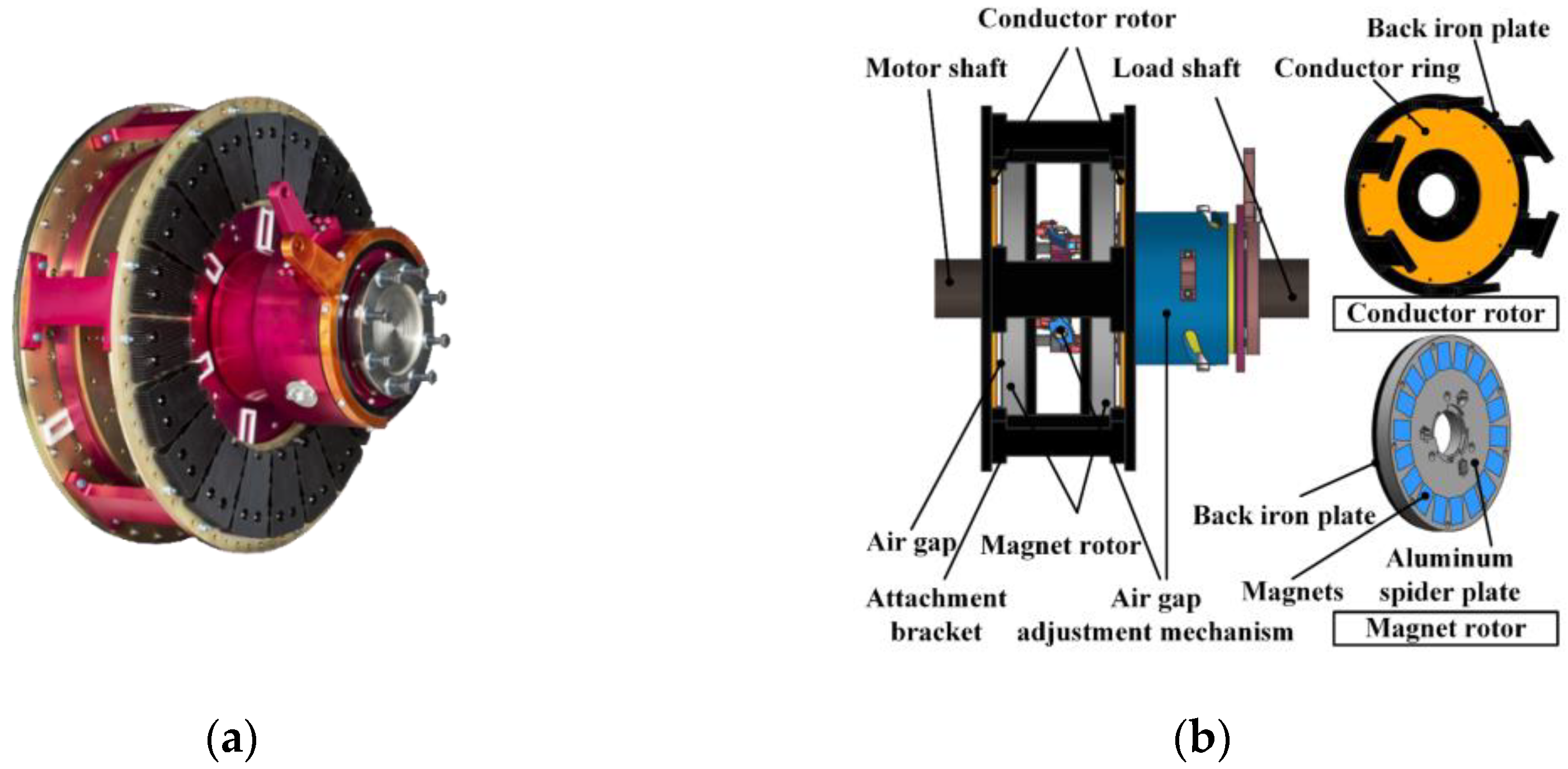
Figure 4.
Two types of axial-flux PMECC: (a) surface-mounted; (b) surface-inset.
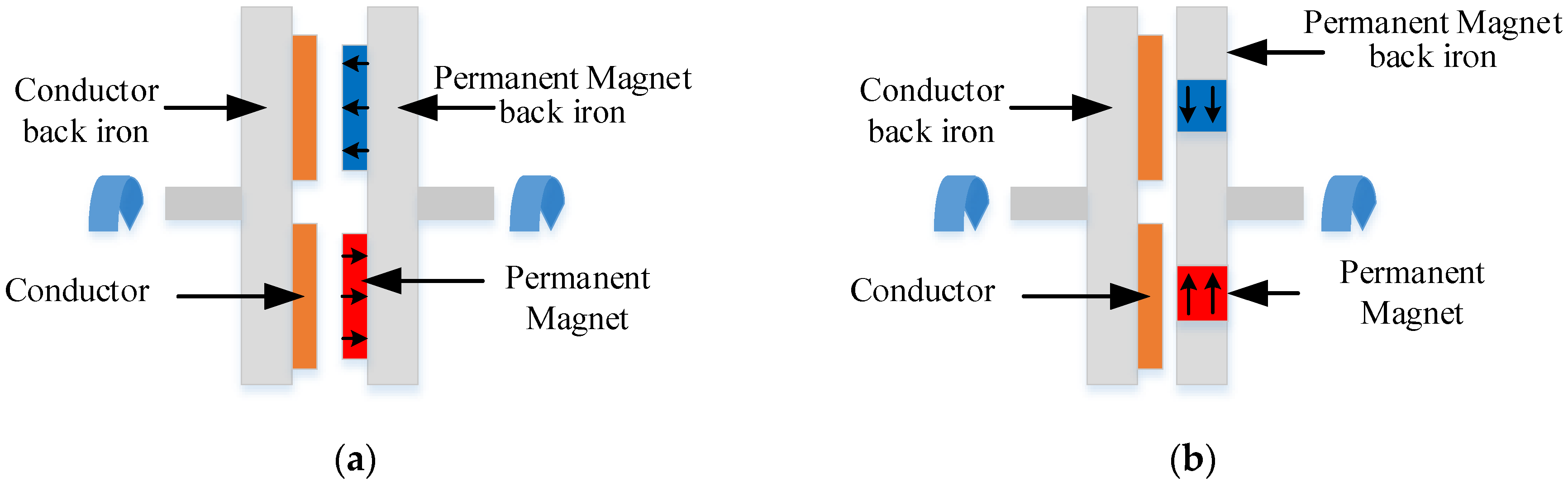
Figure 5.
Double-sided structure PMECC: (a) conductor disk in the middle [82]; (b) PMs in the middle [66].
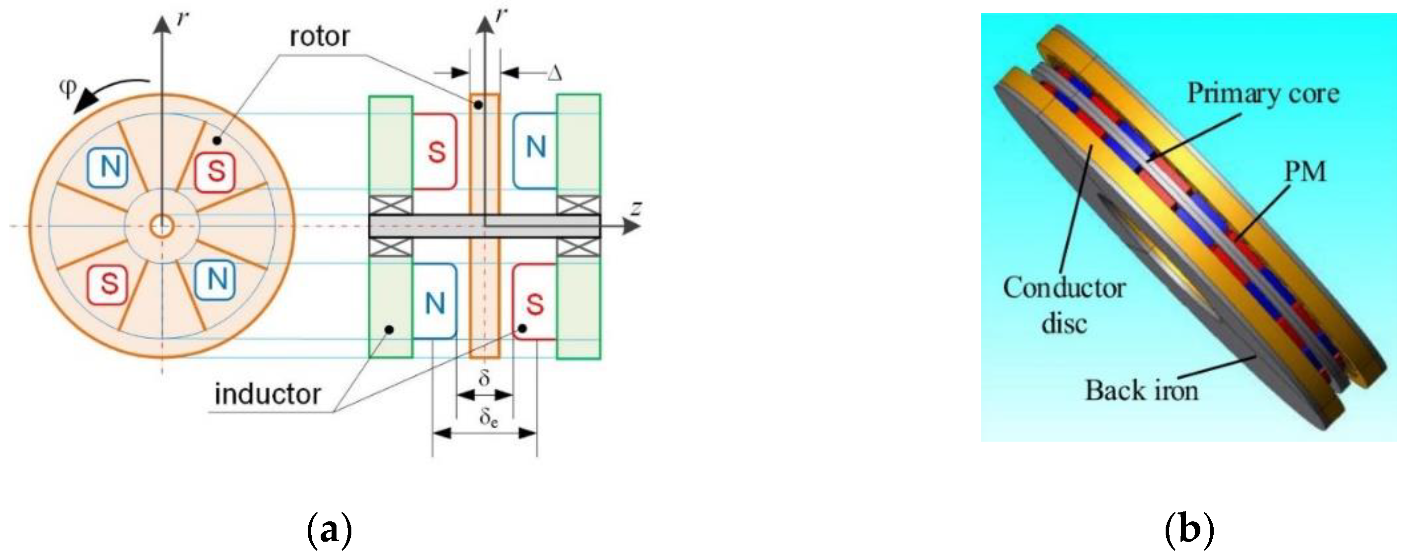
Figure 6.
Two types of surface-inset axial-flux PMECCs: (a) single-side structure [71]; (b) double-side structure [72].
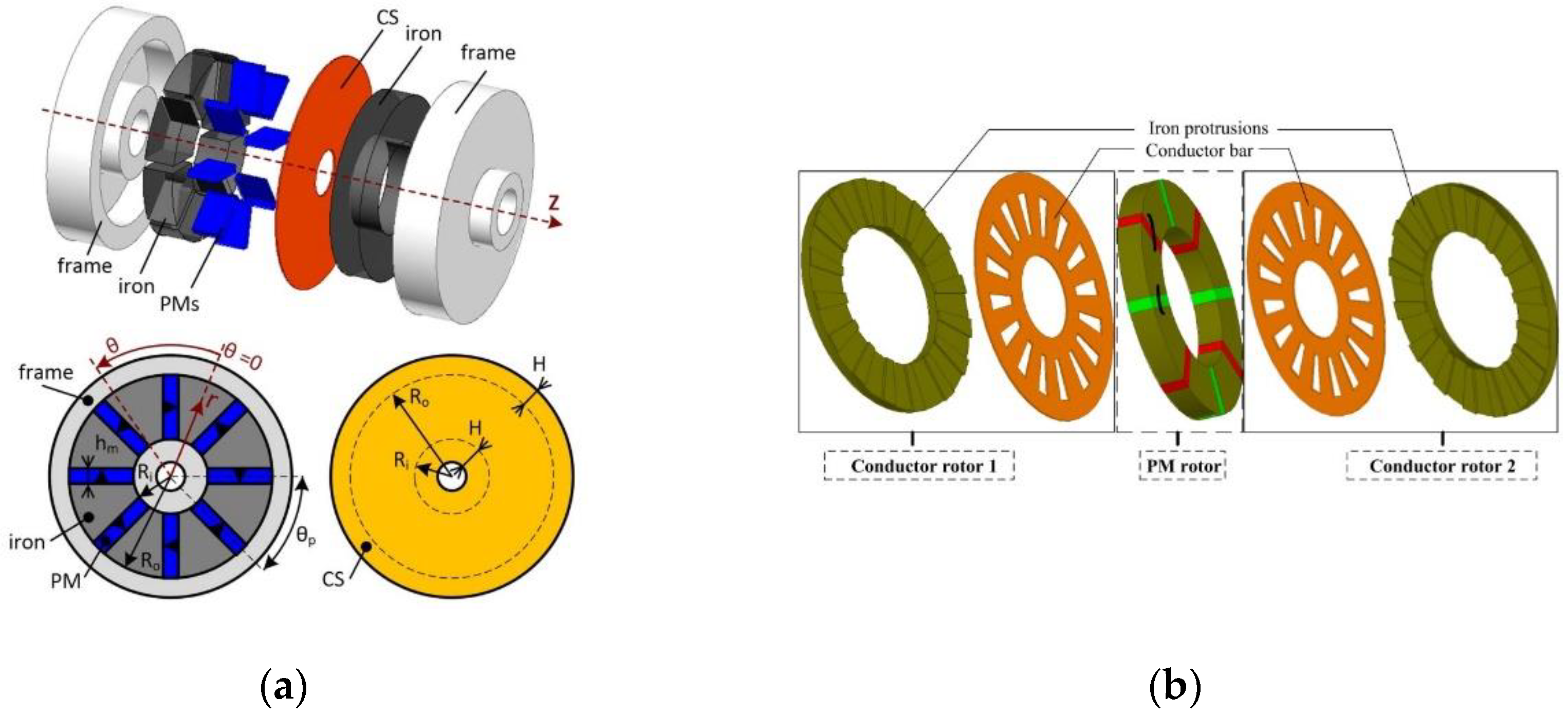
Figure 7.
Two types of radial-flux PMECC: (a) surface-mounted; (b) surface-inset.
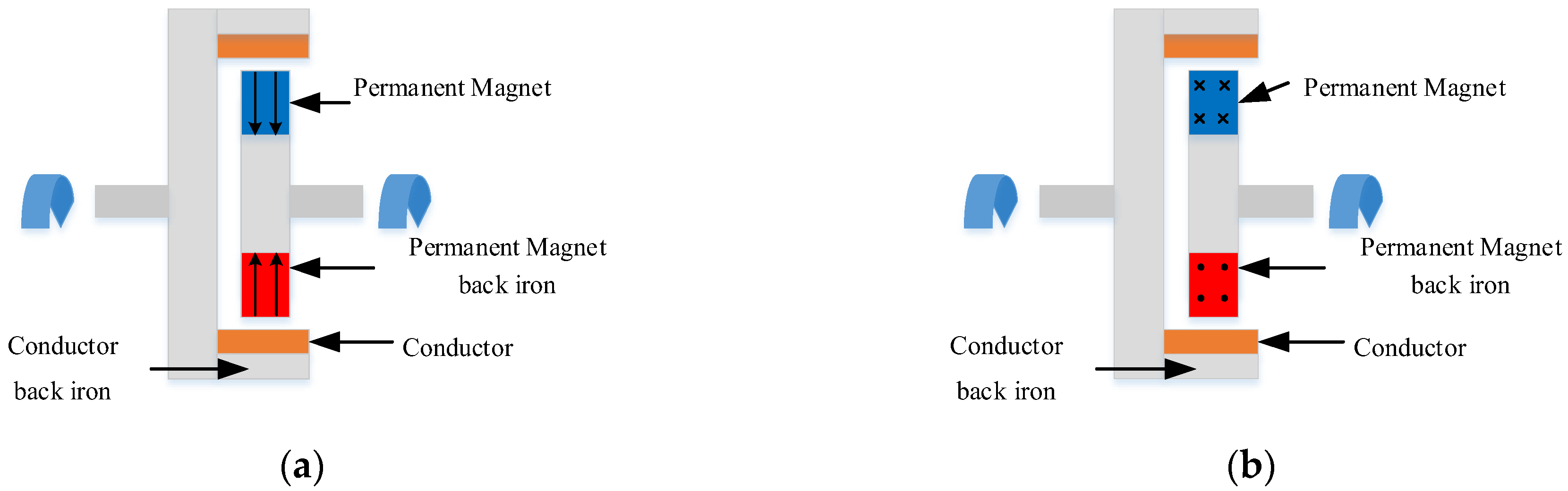
Figure 8.
Double PM-rotor radial-flux PMECC [11].
Figure 8.
Double PM-rotor radial-flux PMECC [11].
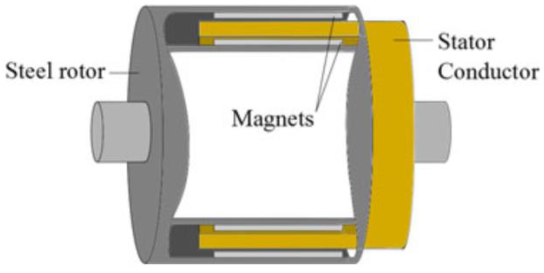
Figure 9.
Surface-inset radial-flux PMECC [105].
Figure 9.
Surface-inset radial-flux PMECC [105].
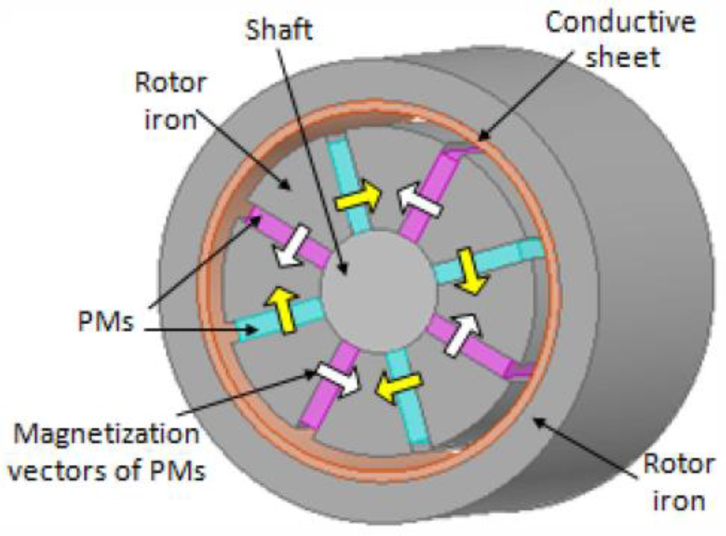
Figure 10.
Axial–radial combined PMECC: (a) non-adjustable axial–radial combined PMECC [34]; (b) adjustable axial–radial combined PMECC [109].
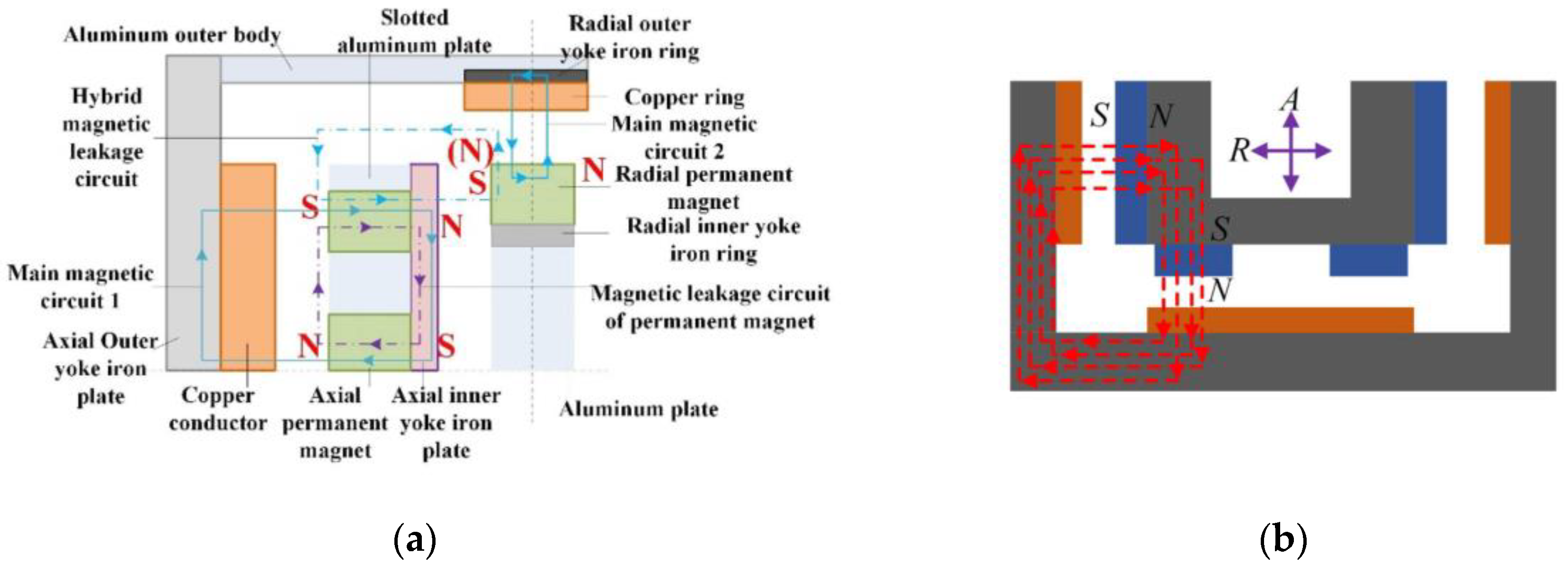
Figure 11.
Four-layer field model for a quasi-Halbach PMECC [111].
Figure 11.
Four-layer field model for a quasi-Halbach PMECC [111].

Figure 12.
Axial flux PMECC with slotted conductor rotor type [117].
Figure 12.
Axial flux PMECC with slotted conductor rotor type [117].

Figure 13.
A novel flux adjustable PMECC: (a) single-sided conductor [122]; (b) double-sided conductor [123].
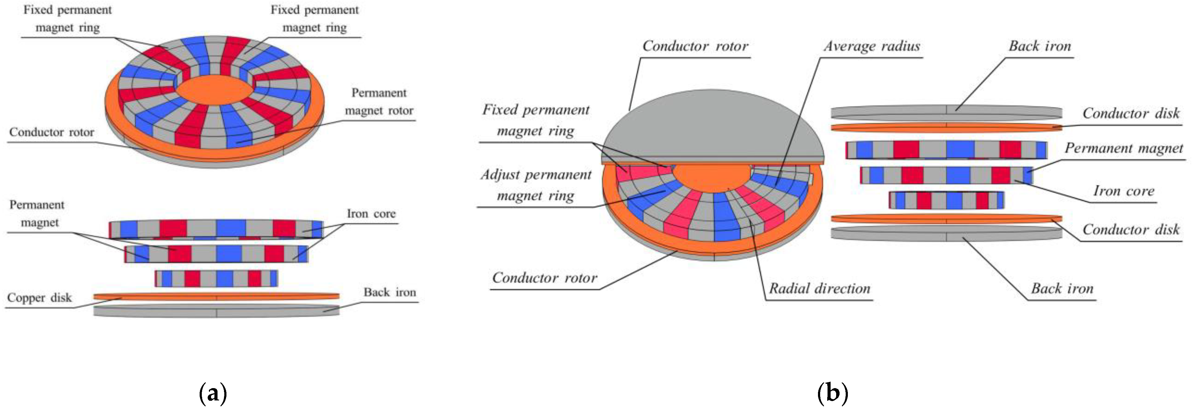
Figure 14.
Functional block diagram of the first-type MEC model [71].
Figure 14.
Functional block diagram of the first-type MEC model [71].

Figure 15.
Relation diagram of the influence of sensitive parameters on transmission performance [31].
Figure 15.
Relation diagram of the influence of sensitive parameters on transmission performance [31].

Figure 16.
Equivalent circuit of conductor volume element [68].
Figure 16.
Equivalent circuit of conductor volume element [68].

Figure 17.
Flow chart of semi-analytical model [30].
Figure 17.
Flow chart of semi-analytical model [30].
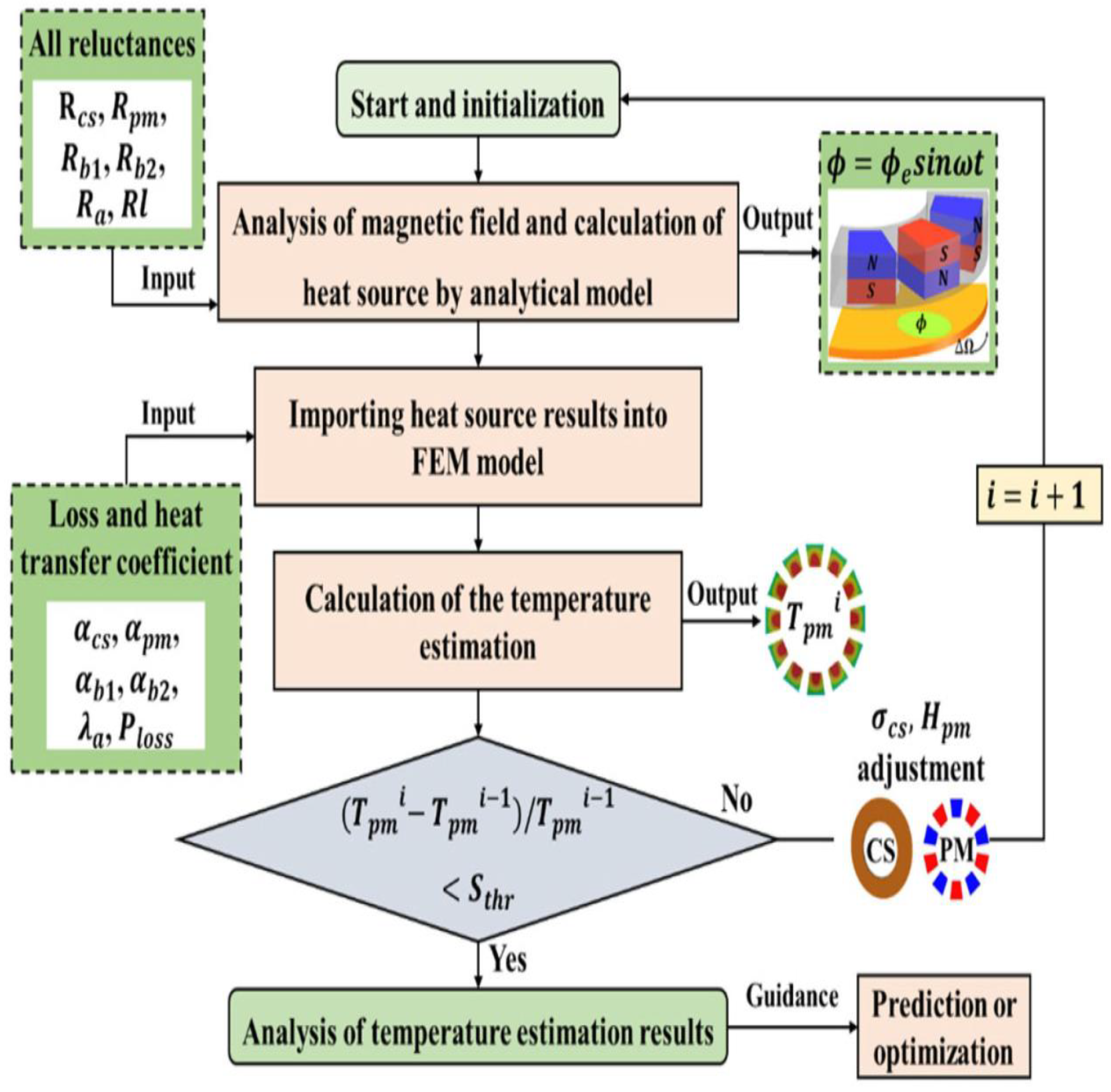
Figure 18.
Equivalent thermal network of the PMECC [31].
Figure 18.
Equivalent thermal network of the PMECC [31].
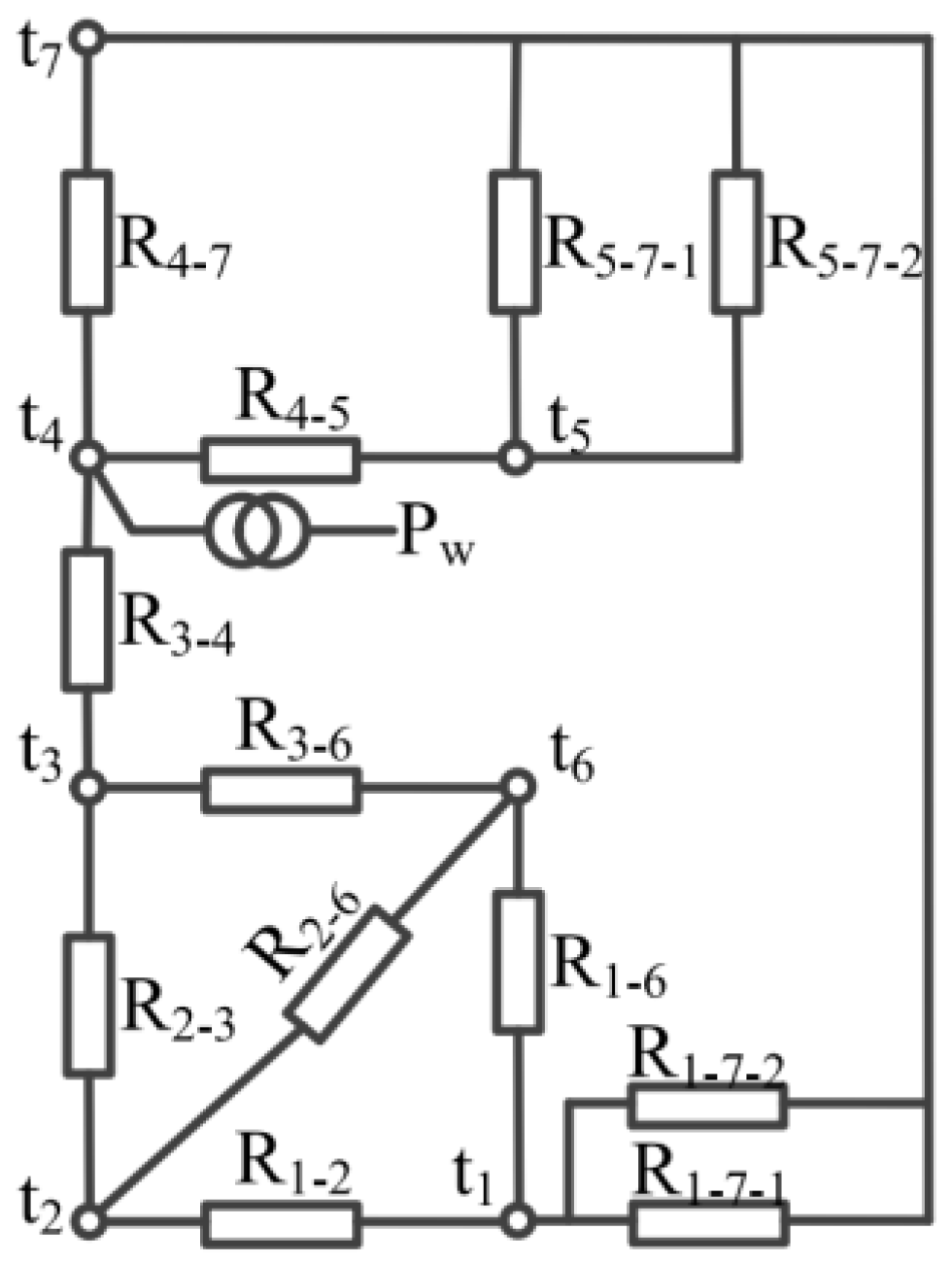
Figure 19.
B–H curve of PM under different temperatures [142].
Figure 19.
B–H curve of PM under different temperatures [142].
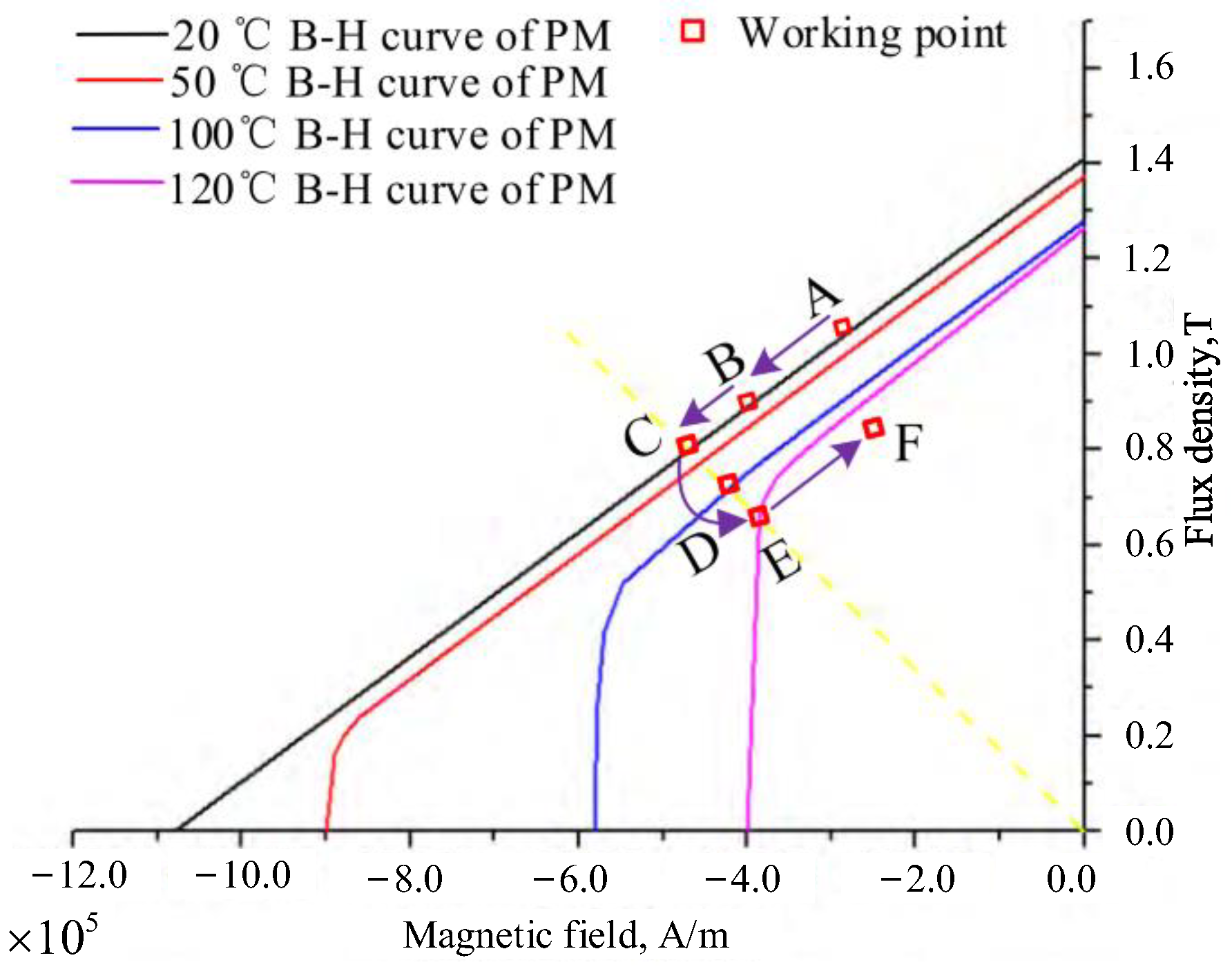
Figure 20.
Flow chart of two-way coupling calculation [142].
Figure 20.
Flow chart of two-way coupling calculation [142].
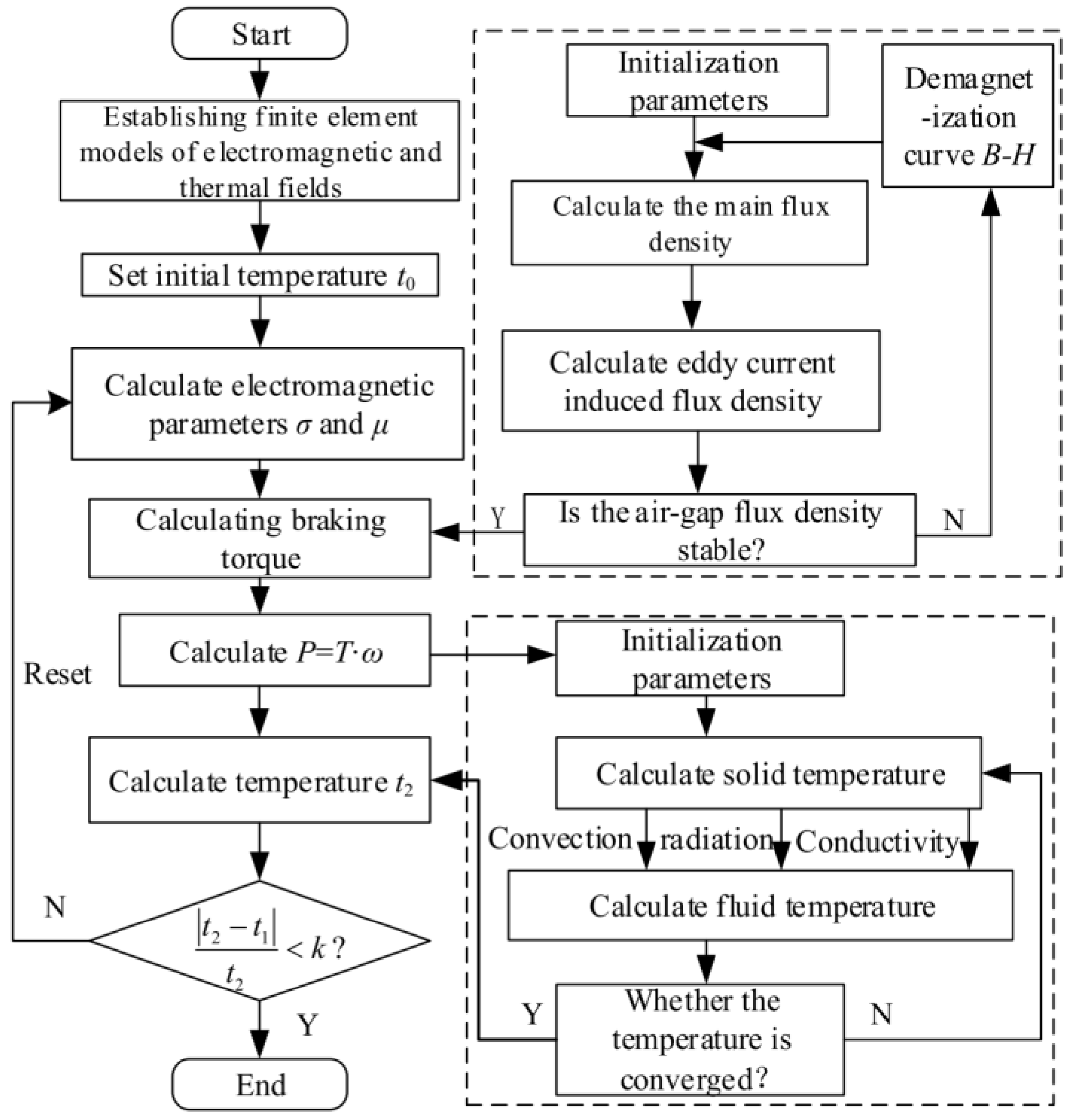
Figure 21.
Flow chart of basic GA [102].
Figure 21.
Flow chart of basic GA [102].
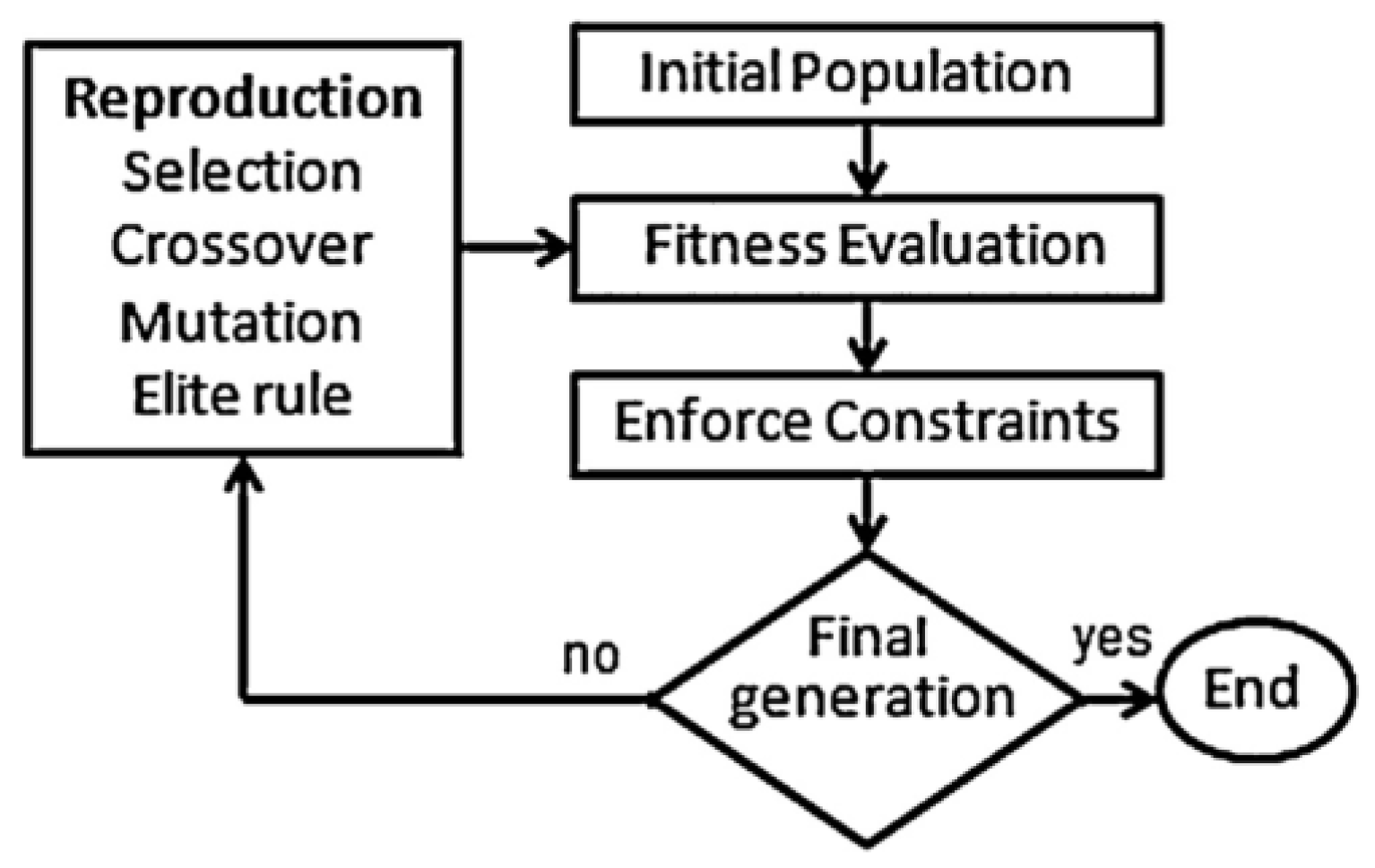
Figure 22.
Flow chart of particle swarm algorithm (PSO) [38].
Figure 22.
Flow chart of particle swarm algorithm (PSO) [38].
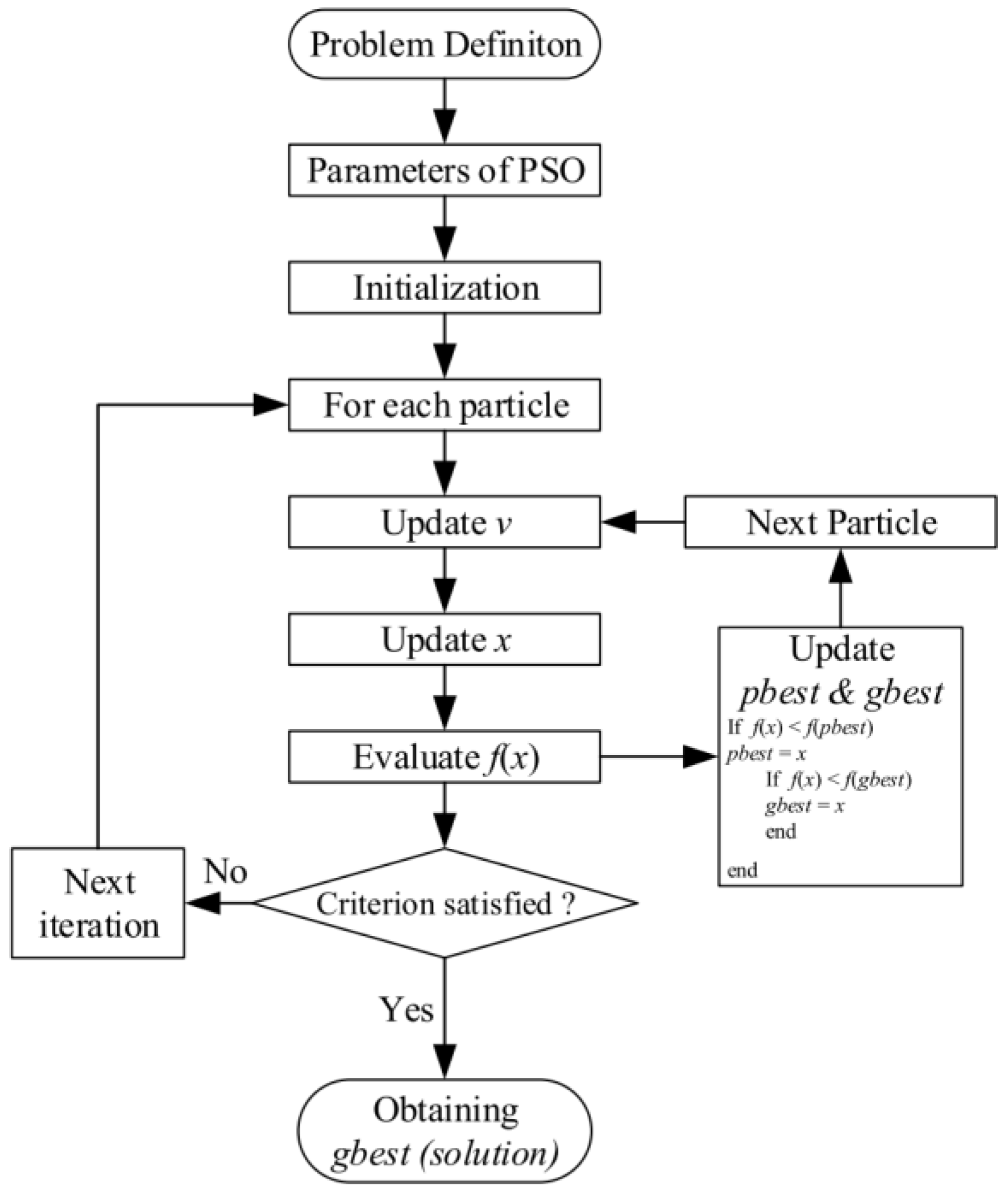

Table 1.
Summary and comparison of various analytic models based on Maxwell’s equations.
| Coordinate | Dimension | Reference System | Reference |
|---|---|---|---|
| Cartesian coordinate | 2-D | PM + Conductor Rotor | [77] |
| Cartesian coordinate | 2-D | PM Rotor | [67] |
| Cartesian coordinate | 2-D | Conductor Rotor | [72] |
| Cartesian coordinate | 2-D | Conductor Rotor | [117] |
| Cartesian coordinate | 2-D | Conductor Rotor | [104] |
| Cartesian coordinate | 3-D | PM Rotor | [79] |
| Cartesian coordinate | 3-D | Conductor Rotor | [58] |
| Cylindrical coordinate | 2-D | PM Rotor | [66] |
| Cylindrical coordinate | 2-D | Conductor Rotor | [72] |
| Cylindrical coordinate | 2-D | Conductor Rotor | [117] |
| Cylindrical coordinate | 2-D | Conductor Rotor | [104] |
| Cylindrical coordinate | 3-D | PM + Conductor Rotor | [79] |
| Cylindrical coordinate | 3-D | PM + Conductor Rotor | [58] |
| Cylindrical coordinate | 3-D | Conductor Rotor | [137] |
| Cylindrical coordinate | 3-D | Conductor Rotor | [138] |
| Cylindrical coordinate | 3-D | Conductor Rotor | [115] |
Disclaimer/Publisher’s Note: The statements, opinions and data contained in all publications are solely those of the individual author(s) and contributor(s) and not of MDPI and/or the editor(s). MDPI and/or the editor(s) disclaim responsibility for any injury to people or property resulting from any ideas, methods, instructions or products referred to in the content. |
© 2023 by the authors. Licensee MDPI, Basel, Switzerland. This article is an open access article distributed under the terms and conditions of the Creative Commons Attribution (CC BY) license (https://creativecommons.org/licenses/by/4.0/).
Share and Cite
MDPI and ACS Style
Wang, J.; Wang, D.; Wang, S.; Tong, T.; Sun, L.; Li, W.; Kong, D.; Hua, Z.; Sun, G. A Review of Recent Developments in Permanent Magnet Eddy Current Couplers Technology. Actuators 2023, 12, 277. https://doi.org/10.3390/act12070277
AMA Style
Wang J, Wang D, Wang S, Tong T, Sun L, Li W, Kong D, Hua Z, Sun G. A Review of Recent Developments in Permanent Magnet Eddy Current Couplers Technology. Actuators. 2023; 12(7):277. https://doi.org/10.3390/act12070277
Chicago/Turabian StyleWang, Jiaxing, Dazhi Wang, Sihan Wang, Tailai Tong, Lisong Sun, Wenhui Li, Deshan Kong, Zhong Hua, and Guofeng Sun. 2023. "A Review of Recent Developments in Permanent Magnet Eddy Current Couplers Technology" Actuators 12, no. 7: 277. https://doi.org/10.3390/act12070277
Note that from the first issue of 2016, this journal uses article numbers instead of page numbers. See further details here.