Review

Unlocking the Potential of Cable-Driven Continuum Robots: A Comprehensive Review and Future Directions

1
Nottingham Ningbo China Beacons of Excellence Research and Innovation Institute, School of Computer Science, University of Nottingham Ningbo China, Ningbo 315048, China
2
Ningbo Institute of Materials Technology and Engineering, Chinese Academy of Sciences, Ningbo 315201, China
3
Zhejiang Key Laboratory of Robotics and Intelligent Manufacturing Equipment Technology, Ningbo 315201, China
4
Department of Electrical and Electronic Engineering, University of Nottingham Ningbo China, Ningbo 315199, China
5
University of Chinese Academy of Sciences, Beijing 100049, China
6
Faculty of Mechanical Engineering & Mechanics, Ningbo University, Ningbo 315211, China
7
Department of Mechanical Engineering, City University of Hong Kong, Hong Kong 999077, China
*
Authors to whom correspondence should be addressed.
Actuators 2024, 13(2), 52; https://doi.org/10.3390/act13020052
Submission received: 31 December 2023 / Revised: 28 January 2024 / Accepted: 29 January 2024 / Published: 31 January 2024
(This article belongs to the Section Actuators for Robotics)

Abstract

:
Rigid robots have found wide-ranging applications in manufacturing automation, owing to their high loading capacity, high speed, and high precision. Nevertheless, these robots typically feature joint-based drive mechanisms, possessing limited degrees of freedom (DOF), bulky structures, and low manipulability in confined spaces. In contrast, continuum robots, drawing inspiration from biological structures, exhibit characteristics such as high compliance, lightweight designs, and high adaptability to various environments. Among them, cable-driven continuum robots (CDCRs) driven by multiple cables offer advantages like higher dynamic response compared to pneumatic systems and increased working space and higher loading capacity compared to shape memory alloy (SMA) drives. However, CDCRs also exhibit some shortcomings, including complex motion, drive redundancy, challenging modeling, and control difficulties. This study presents a comprehensive analysis and summary of CDCR research progress across four key dimensions: configuration design, kinematics and dynamics modeling, motion planning, and motion control. The objective of this study is to identify common challenges, propose solutions, and unlock the full potential of CDCRs for a broader range of applications.

1. Introduction

1.1. Origins of Continuum Robots

Rigid robots have found wide-ranging applications in manufacturing automation, owing to their high loading capacity, high speed, and high precision [1,2,3]. However, these robots typically feature joint-based drive mechanisms with limited degrees of freedom (DOF) and bulky structures, making it difficult for them to perform tasks in narrow and cluttered workspaces, such as gastroenteric operations and cave rescue missions [4]. To address such challenges, bio-inspired continuum robots, which have unique characteristics, such as high compliance, lightweight designs, and high adaptability to various environments, have received increasing attention in the robotics community [5,6,7].
The concept of continuum robots dates to the 1960s [4,8], but it was not formally introduced until 1999 [9]. Continuum robots are typically defined by their hyperflexible electromechanical structures with infinite degrees of freedom, which provide them with the ability to maneuver complex curvilinear pathways [10]. In comparison to rigid robots, continuum robots stand out for their continuous deformation capabilities, allowing them to adapt effectively to various environmental conditions and execute corresponding tasks [11]. For instance, the snake’s spine, capable of coiling and traveling, has inspired the creation of various continuum robots [12]. These robots are typically defined as having much more kinematically drivable DOF than the DOF of the robot’s workspace [13]. Additionally, nature’s examples, such as elephant trunks, octopus tentacles [14], frog tongues [15], and earthworms [5], exhibit continuous muscle tissue [16] and offer diverse functions, including expansion, coiling, grasping, and adsorption, despite the lack of rigid material support. Continuum robots, as a result, exhibit exceptional flexibility and freedom of motion. Notably, not all DOF are directly actuated [13]. However, they are often underactuated as researchers aim to achieve the desired manipulator positions with as few drives as possible to reduce the hardware cost. As results, despite their theoretical unlimited DOF [17], many continuum robots are often equipped with fewer drives than their DOF suggests, striving for optimal balance.
Recent advancements in materials science, sensing technologies, and control algorithms have led to an increased interest in and research on continuum robots. Today, these robots find applications in various fields [18], including medicine, rescue operations [19], manufacturing, aerospace, nuclear facilities [20,21], and more. In medicine, continuum robots enable minimally invasive surgery and endoscopy [22]. In manufacturing, they facilitate assembly and welding. In aerospace, they assist in space maintenance and satellite servicing. In ocean engineering, they are employed for seabed exploration and pipeline maintenance [23].

1.2. Classification of Continuum Robots

Common continuum robots can be categorized based on their driving methods into three main types: pneumatic, cable-driven, and SMA-driven.
  • Pneumatic continuum robots rely on air pressure as their driving force [24]. They are known for their high flexibility, simple structures, smooth movement, and lightweight construction [25]. Typically, these robots consist of multiple pneumatic chambers, with robot movement achieved by controlling changes in air pressure [26,27]. Nevertheless, pneumatic continuum robots have limitations, including restricted precision, noise generation, and high maintenance costs.
  • SMA-driven continuum robots use shape memory alloys, special metal alloys known for their memory shape and superelasticity [28], as their driving mechanism. They exploit the SMA’s memory shape and superelastic properties to enable bending and torsion of flexible segments, facilitating the robot’s movement and operations [29,30]. SMA-driven continuum robots offer advantages such as simple driving devices, fast response times, and low power consumption. However, they are also susceptible to drawbacks like high material costs, low load capacity, and sensitivity to temperature and stress.
  • Cable-driven continuum robots, sometimes referred to as tendon-driven or line-driven robots, rely on flexible supporting structures (backbones) and driving cables to achieve motion by adjusting cable lengths and tension [31,32,33]. These robots can change shapes and positions continuously, making them lightweight and intrinsically safe. They are particularly suited for more precise operations in confined spaces and exhibit smaller response lag compared to pneumatic robots [34,35,36]. They also offer a larger working space and higher load capacity compared to SMA-driven systems. However, CDCRs face challenges such as complex motion, modeling difficulty, low control accuracy, actuation redundancy, and relatively large drive mechanisms. Consequently, the design analysis, kinematics and dynamics modelling, motion planning, and control for CDCRs have become complex interdisciplinary fields that attract growing interest among researchers.
This study primarily focuses on CDCRs, aiming to provide a comprehensive review of their design, modeling, motion planning, and control. The paper’s structure is as follows: Section 2 discusses the considerations for configuring CDCRs, addressing aspects such as backbone selection, cable arrangement, moving platform positioning, and material selection for various components. In Section 3, the paper delves into the kinematics and dynamics of these robots, summarizing various modeling and optimization methods. Section 4 introduces existing motion planning algorithms for CDCRs, including the “follow-the-leader” method and other mainstream approaches. In Section 5, various motion control methods are categorized, analyzed, and compared. The final section offers a summary and outlook for the paper, emphasizing the potential applications of these robots in a wide range of fields.

2. CDCR Configurations and Cable Arrangements

The design of CDCRs involves a multi-faceted process, demanding a meticulous evaluation of several critical parameters. This mainly includes the robot’s length, diameter, bending radius, weight, and load capacity, as well as cable tension, diameter, material, layout, and adherence to force closure conditions [37]. CDCRs are usually composed of a backbone, moving platform, and drive mechanism, in which the design of the backbone plays a pivotal role. The overarching aim of this process is to equip the robot with the desired level of flexibility and controllability while upholding its stability and reliability.

2.1. CDCR Configurations with Different Backbone Stuctures

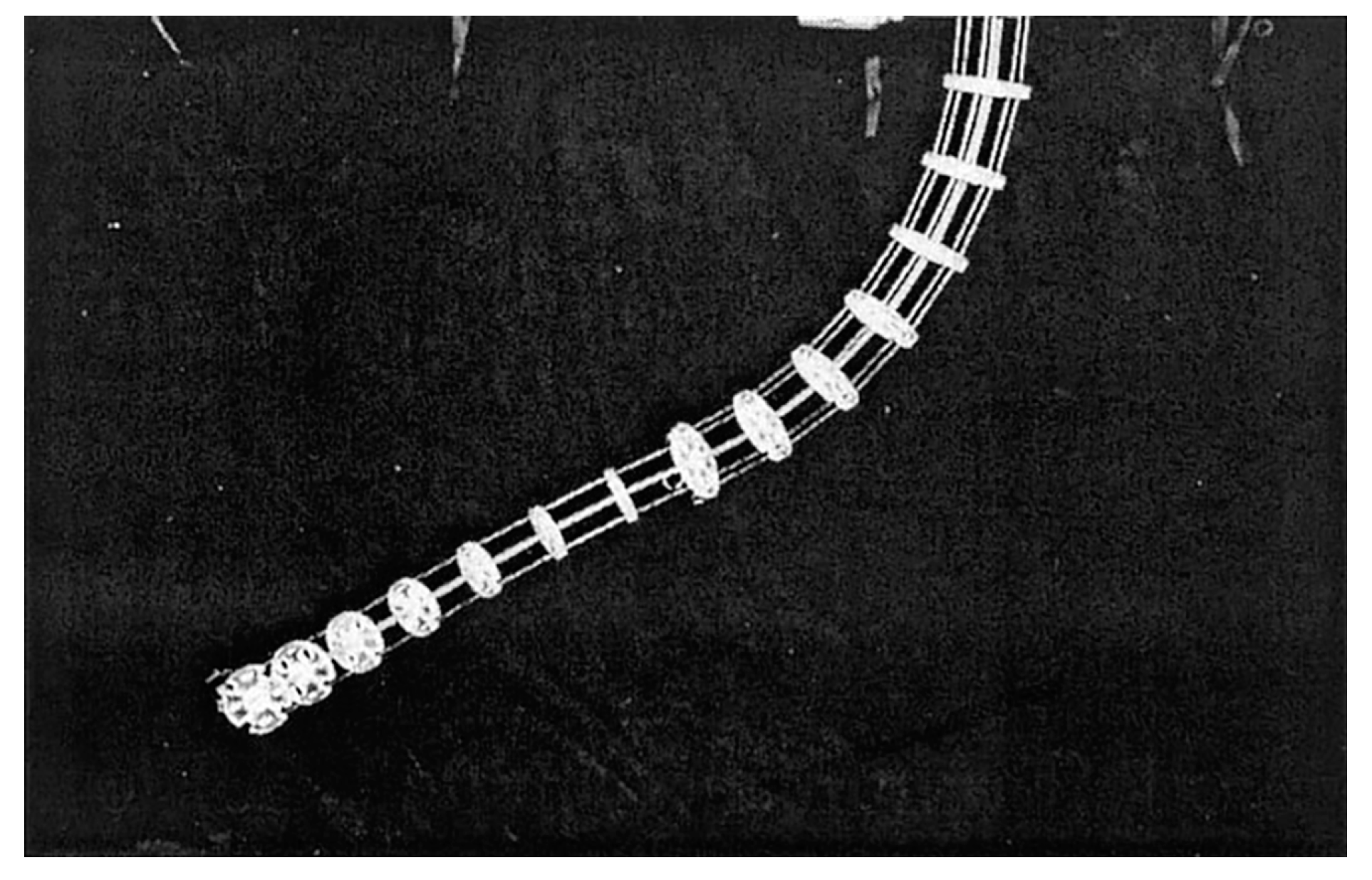
2.1.1. CDCR with Sheet Type Backbone

The earliest prototype of a CDCR, conceived by Walker et al. at Clemson University in 2000, serves as an exemplary illustration of a fundamental design (see Figure 1) [38,39]. Comprising 11 joints and propelled by just two cables, this robot featured a sheet spring steel backbone. Despite being constrained to a 1-DOF, empirical evidence demonstrated that the robot could maintain its end-effector orientation even in the presence of external forces near the base. Notably, the trajectory of the backbone was primarily governed by minimizing potential energy, while controlling end-effector orientation necessitated setting boundary conditions and adhering to system constraints. This configuration is well-suited for theoretical investigations and laid the groundwork for mathematical models relating cable length to backbone bending. It also introduced the challenge of optimizing the number of moving platforms to minimize cable friction while maintaining shape equilibrium.

2.1.2. CDCR with Rod Type Backbone

In 2001, the Clemson tentacle manipulator was enhanced [40], featuring two independent parts with 2-DOF each (see Figure 2). The flexible thin rod served as the backbone, and cable guides were periodically spaced along its length. Four pairs of cables traversed these guides, with two pairs terminating at the midpoint and two pairs at the end. Varying cable tension allowed torque to be applied orthogonally either at the midpoint or the end of the manipulator trunk. This classic configuration not only provided valuable foundational insights but also served as a source of inspiration for subsequent advancements in CDCRs.
In 2011, Webster et al. at Vanderbilt University pioneered a 2-DOF continuum robot dedicated to the study of robot statics and dynamics [41], showcased in Figure 3a. This configuration comprises 12 arm discs, with 10 serving as passive discs to guide the tendon. The tendons themselves consist of Teflon-coated fiberglass thread, while the frame is constructed from spring steel rods [41]. However, experimental results revealed that the robot’s weight alone induces significant deformation. Building upon this design, Pinhas et al. at George Washington University developed a similar configuration since 2012 to facilitate the comparison of the virtual power models they were investigating [42,43]. Similarly, their design (Figure 3b) features a spring steel backbone, equidistantly drawn with three glass fiber cables. Their main purpose is to study its dynamic properties. It is evident that the manipulator structure of both studies is relatively straightforward, providing only 2-DOF, making it particularly well-suited for theoretical research.

2.1.3. Modular CDCR with Rod Type Backbone

Beginning in the last decade, researchers began to focus on the development of CDCRs, with notable advancements. Between 2010 and 2014, Yang et al. at Nanyang Technological University introduced a cable-driven flexible snake-like robot prototype [36,44,45]. This design adopts a modular approach, comprising multiple identical rod-driven joint modules in series (Figure 4). Each module includes a base disk, three cables, an elastic backbone, and a mobile platform, resulting in a remarkable total of 8-DOF. These robots employ motors to drive the cable coils, offering exceptional versatility. However, increasing the number of active joints and the distance between arm disks introduced challenges, notably the formation of S-shaped deformations in the robot’s structure. Several factors contribute to this phenomenon, including the interaction of dead weight and external loads with cable torque and the risk of buckling deformations due to cable tension.

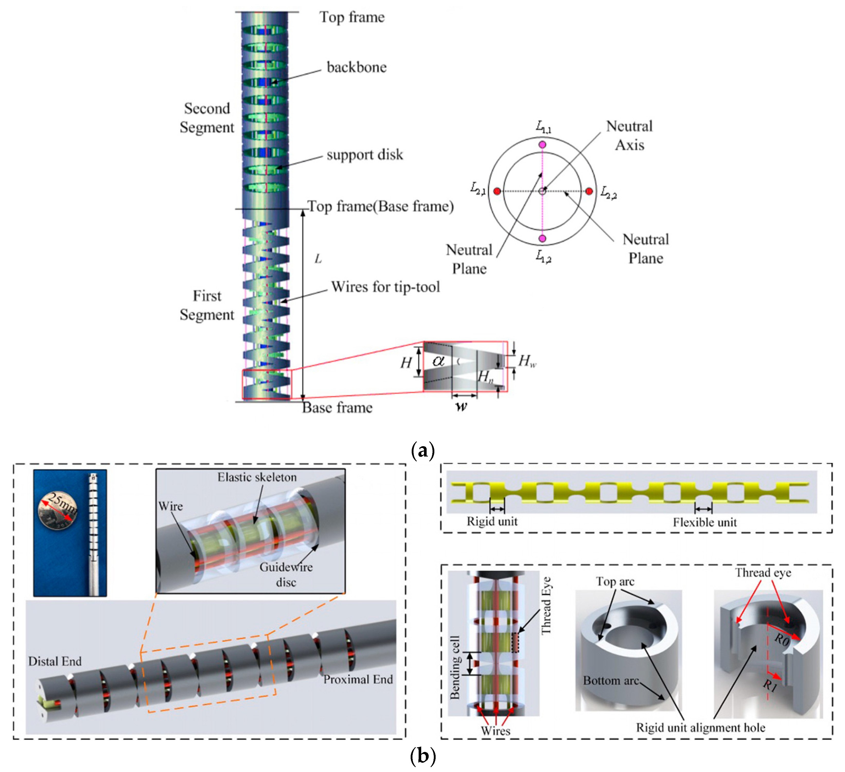
2.1.4. CDCR with Notch Elastic Backbone

In 2013, Du et al. at Harbin Institute of Technology introduced a continuum robot featuring a novel triangular notch design for the first time [46], depicted in Figure 5a. In this design, a cable is driven through a two-sided symmetrical channel within a nickel-titanium tube, enabling a 1-DOF bending movement within a plane. By employing joint superposition, a 2-DOF manipulator can be realized. Recognizing the initial design’s limitations in terms of DOF, the study introduced an updated configuration in 2020 [47] with alternating orthogonal incisions, as illustrated in Figure 5b. This revised continuum robot incorporates a notched elastic backbone (constructed from Nitinol) and a guide reel for decoupling purposes. Similar to an exoskeleton, this design conveniently reserves channels in the interior to accommodate signal lines for energy devices and vision units. Two opposing sets of cables provide 2-DOF actuation. This exoskeleton design enhances the manipulator’s load-bearing capacity. However, due to the freedom constraints, the degree of bending at each incision cannot be individually controlled, which may affect the manipulator’s attitude when transitioning between load-bearing modes or directions.
In 2021, Dong et al. from the University of Nottingham developed a continuum robot [48,49,50] designed for on-site maintenance of aero engine combustion chambers, as seen in Figure 6. This robot is divided into two main parts, with the end section comprised of three parts with 2-DOF each, while the body comprises ten 1-DOF segments. A linear platform is utilized to maneuver the entire robot in and out of the aero engine during navigation. Similar to Du et al.’s [46] manipulator, this design features arm discs assembled in a vertebrae-like structure, interconnected by Ni-Ti alloy rods acting as a backbone, with cables threaded through the arm discs. This configuration indeed addresses the S-shaped deformation issue to some extent and enhances the manipulator’s load-bearing capacity. However, the range of bending angles is constrained by the shape of the arm discs, which impacts the effective working space of the manipulator and introduces coupling between each group of arm discs.

2.1.5. CDCR with Extensible Backbone

In 2006, NASA developed the Tendril continuum robot [51] specifically designed for inspection operations in outer space, depicted in Figure 7a. This innovative robot utilizes tandem springs as its backbone to maintain a slender profile and lightweight construction. While gravity’s influence can be discounted in space, the choice of springs as the backbone introduces a pronounced coupling effect among the joints, often resulting in buckling phenomena, characterized by severe S-shaped deformation. However, in 2015, Walker et al. at Clemson University significantly improved its performance [52,53], as illustrated in Figure 7b. In this enhanced design, the manipulator is divided into three segments, each endowed with 3-DOF—two for bending and one for telescoping. The entire manipulator boasts 9-DOF in total. It employs concentric tubes with approximately constant curvature (CC) as its backbone, supplemented by springs to manage expansion and three cables per joint to govern bending motion. Multiple passive arm discs are incorporated within each joint to ensure that the cable follows a continuous, smooth bending trajectory, thus maintaining circular deformation. This continuum robot boasts a high aspect ratio and a streamlined design, ultimately enhancing the weight-power ratio and compactness. These features render it more reliable for operation in a gravity-free environment.
Another scalable continuum robot was developed in 2015 [54,55] by Jessica et al. at Leibniz Universitaet Hannover, depicted in Figure 8. The telescopic principle is realized by floating arm discs along the robot’s backbone. Within the manipulators, permanent magnets are embedded, aligned in the direction of alternating magnetic poles. The resulting magnetic repulsion ensures that the manipulators are evenly distributed along the main stem. The backbone adopts a concentric tubular structure, segmented into three sections, and is crafted from nickel–titanium alloy. This design employs three driving cables, affording a total of 9-DOF, comprising six degrees of bending and three degrees of telescopic freedom. The reduced distance between manipulators and the magnetic repulsion between the magnets contribute to the enhanced rigidity of the entire manipulator, mitigating buckling deformation issues. Additionally, scalable continuum robots offer distinct advantages in the domain of robot motion planning.

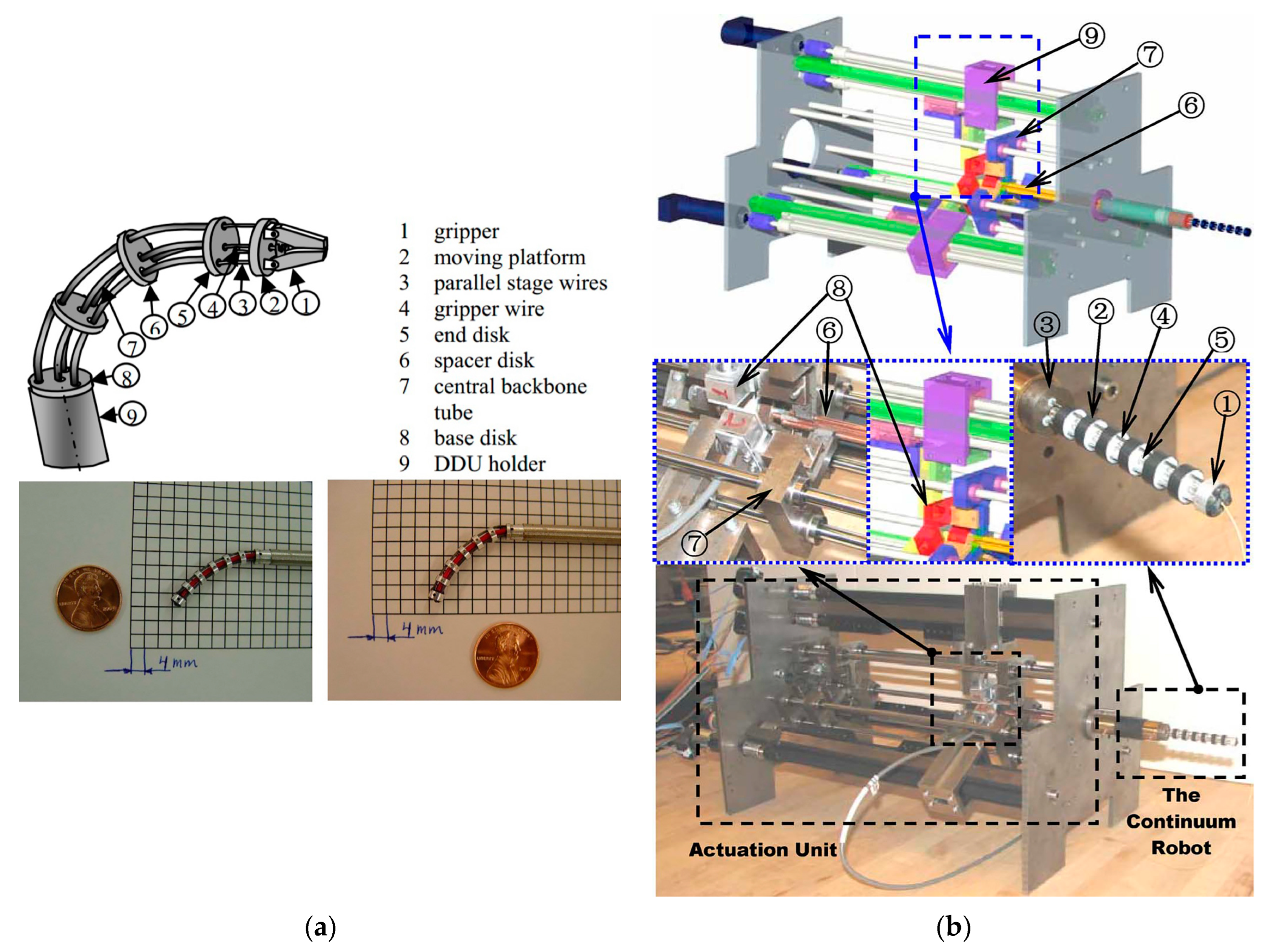
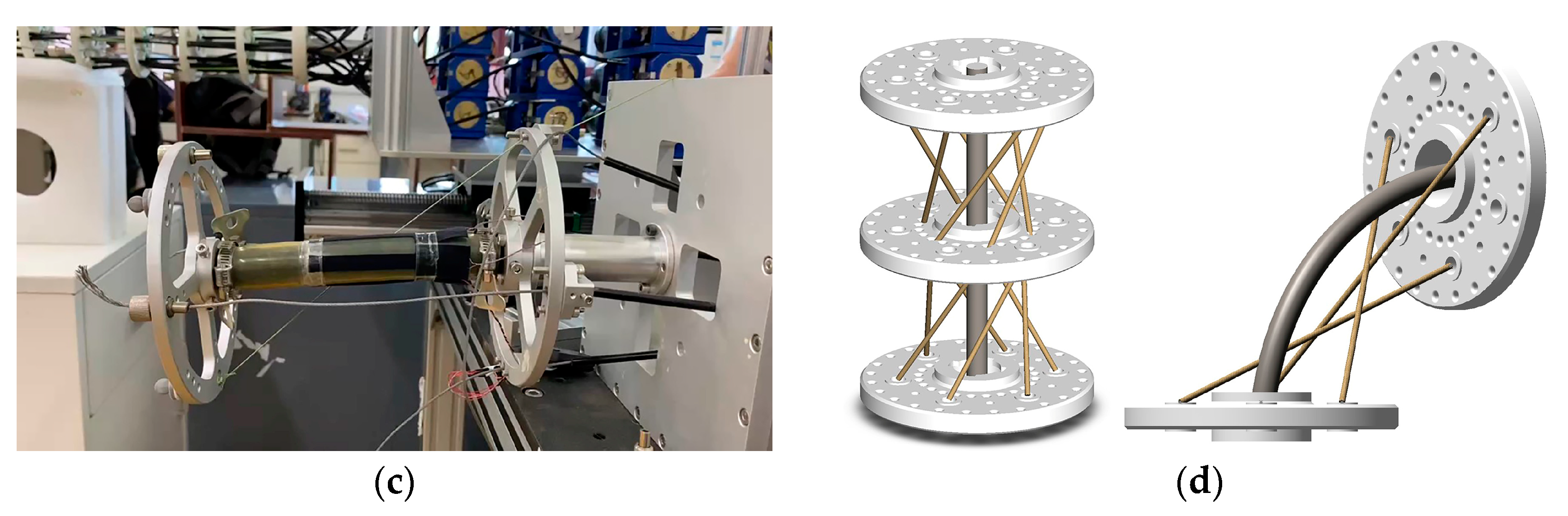
2.1.6. CDCR with Multi-Backbone

In 2004, Simaan et al. at Johns Hopkins University introduced a sophisticated system tailored for laryngeal surgery [56]. At its core are three distal dexterity units (DDU), essentially miniature continuum robots (Figure 9a). The DDU comprises a base disk, an end disk, a series of spacer disks, and four hyperelastic tubes, serving as the robot’s backbone. Among these tubes, one is the central main backbone, while the other three act as secondary backbones. Remarkably, these secondary backbones serve dual purposes: they provide support to prevent buckling deformations and act as driving mechanisms, eliminating the need for traditional cables. This innovative approach enables bidirectional motion through a push–pull mechanism. The robot’s primary and secondary frames are constructed from superelastic nickel–titanium tubes and offer 1-DOF. In 2008, Xu [57] from Columbia University enhanced this concept by achieving 2-DOF through the simultaneous actuation of three secondary backbones (Figure 9b). This improvement allowed for precise control while maintaining structural rigidity.
In the 2020s, the scientific community began to recognize the pressing issues confronting continuum robots. Researchers from Tianjin University introduced a variable stiffness continuum robot [58,59] aimed at mitigating the S-shaped deformation problem commonly associated with these robots. As depicted in Figure 10, this innovative design features a backbone crafted from a medium NiTi alloy. Instead of traditional cables, it employs three NiTi alloy drive rods distributed at 120-degree intervals to drive the robot. These drive rods facilitate bidirectional motion and share the load-bearing responsibility of the mechanical manipulator, effectively increasing its overall stiffness. Notably, this structure lends itself to achieving force closure conditions. In Figure 10, it can be observed that three sets of levers are assembled on pairs of adjacent arm discs. By controlling whether the SMA spring locks onto the drive rod, it plays a crucial role in fixing a specific joint angle. This mechanism enables variable stiffness control and alleviates the problem of S-shaped deformation in the backbone. The SMA springs exhibit a high power-to-weight ratio, offering flexibility and compactness that make them suitable for installation in slender, narrow continuum robots. However, it is important to note that using the drive rod occupies a certain amount of space within the manipulator, resulting in just two active joints throughout the robot, providing 4-DOF. Additionally, the SMA lock can achieve the ideal configuration when the manipulator is unloaded. However, if an initial load is applied, the manipulator may be unable to perform actions such as lifting the entire manipulator.

2.1.7. Discussions on Backbone Structures

The configurations of continuum robots throughout different eras are briefly summarized in Table 1. It is realized that traditional continuum robots have typically grappled with S-shaped deformation and uncontrollable translational DOF, thereby affecting manipulator accuracy and load-bearing capacity. Furthermore, these robots tend to have limited overall DOF, resulting in a relatively small reachable and dexterous workspace, one which does not fully exploit the flexibility and compliance advantages offered by continuum robots. Presently, most continuum robots employ a straight-pull cable arrangement, wherein each cable runs parallel to the backbone. This arrangement leads to a singular position when the manipulator is not bent, offering no means to constrain the translational freedom of the arm discs.
Consequently, optimizing cable arrangements to enhance reliability, reduce cable tension, or expand the workspace while maintaining load-bearing capacity is a pressing challenge for CDCRs. A potential source of inspiration comes from examining the distribution of muscles in the trunk of an elephant [60], as illustrated in Figure 11. The trunk’s size and tendon distribution, particularly the oblique muscle layers, are crucial for an elephant’s load-bearing and manipulation abilities. Thus, researching how to incorporate oblique driving or restraining cables to constrain uncontrollable DOF holds promise for future research.

2.2. CDCR Cable Arrangements

The traditional CDCR is controlled by the drive cable. For cable arrangement, if there is a large load bearing, the backbone will show obvious S-shape deformation. This section summarizes the existing arrangements of CDCR cables. The force analysis of different cable arrangements is conducted, and the cause of S-shape deformation is analyzed. In addition, some cable arrangement methods that are helpful to alleviate S-shape deformation of the backbone are also discussed.

2.2.1. Cable Arrangement in Existing CDCRs

In the context of the entire CDCRs, three distinct cable arrangement methods are presented: complete penetration method, partial penetration method, and modular method.
The full penetration method penetrates all the cables through all the moving platform, but the whole arm is only 2-DOF, which is difficult to bear large loads. The partial penetration method involves routing the drive cables through each moving platform, allowing each set of drive cables to influence not only their respective joints but also all the joints they traverse. This method increases the degree of freedom of the whole arm and offers significantly improved load-bearing capacity but introduces multi-joint coupling, which elevates control complexity.
On the other hand, the modular method entails that each set of drive cables independently controls a specific section of the joint, with Bowden cable control, ensuring a straightforward and non-interfering control mechanism. However, the drawbacks are evident, particularly in terms of load-bearing capacity, especially near the base end.

2.2.2. Force Analysis for Different Cable Arrangements

To determine the optimal method for active cable tensioning, a comparative analysis of three distinct cable arrangements was conducted: the parallel cable arrangement, slanted cable arrangement, and slanted cable arrangement with intermediary dick. Simultaneously, the factors contributing to initial manipulator drooping or singularity were also explored. The findings led to the conclusion that the slanted cable arrangement effectively mitigates the sagging of the backbone.
Initially, it is considered that the backbone and moving platform are rigid bodies, allowing us to temporarily ignore the torque’s influence on the interior of the system. The process begins by the analysis of the parallel cable arrangement. When the backbone is in a horizontal position, a force analysis on the rigid body is performed, as depicted in Figure 12a. In the vertical direction, the rigid body experiences both the downward gravitational force G and an upward supporting force F 1 from the base. Horizontally, it is pulled by the cable to the left F 2 and supported by the base to the right F 3 . Notably, G equals F 1 , and F 2 equals F 3 . Moreover, the torque M 1 generated by the forces ( F 1 a n d   G ) is equal and opposite to the torque M 2 generated by the forces ( F 2 and F 3 ). This configuration achieves balance and maintains a horizontal posture.
However, the S-shaped deformation in the horizontal position of the non-rigid backbone (as shown in Figure 12b) results from bending deformation. To analyze the reason for this, the force analysis needs to be repeated first. The positions and magnitudes of the forces remained consistent with those of the rigid body, except that the couple could not move freely within the non-rigid body. Consequently, the positions of the couples had to be marked. As shown in Figure 12a, M 1 acted at point A (located at the midpoint between forces F 1 and G ), while M 2 was located at point B (at the geometric center of the rectangle). Notably, A and B did not coincide, leading to a clockwise bending of M 1 near the base and a subsequent counterclockwise bending of M 2 near the platform. These combined effects resulted in the sagging observed in Figure 12b.
To address this issue and alleviate the manipulator droop caused by M 1 , two methods were contemplated: the oblique cable method and the slanted cable arrangement with intermediary dick. In both cases, the force analyses were conducted, as depicted in Figure 12c for the oblique cable method and Figure 12d for the slanted cable arrangement with intermediary dick. In the oblique cable method, F 2 was decomposed into vertical F 21 and horizontal F 22 components, while gravity G was decomposed into G 1   a n d   G 2 . Our analysis revealed that only M 1 created a clockwise (causing backbone droop) force couple. As G 1 was less than G , M 1 was smaller than M 1 , effectively alleviating the droop issue, thereby confirming the effectiveness of the slanted cable arrangement.
The analysis of slanted cable arrangement with intermediary dick was also completed, as shown in Figure 12d. The left half was considered to have the same effect as the slanted cable arrangement, focusing our analysis on the right half. Just like in the slanted cable arrangement, when decomposing F 2 into F 1 and F 21 , it was evident that M 1 equaled M 1 . While M 3 was also clockwise, it was concentric with M 2 and acted at the same position. When the diagonal tension angle was less than 45 ° , M 3 was smaller than M 2 , thus offsetting the effect of M 2 . A similar analysis was conducted for the lower part, where the horizontal component exceeded the vertical component, suggesting that cable tension in the lower part only generated a clockwise moment. So, this part of the cable was assumed to have no tension. Given that M 1 was equal to M 1 and greater than M 1 , it was evident that the slanted cable arrangement with intermediary dick did not effectively alleviate the sagging condition.

2.2.3. Discussions on Cable Arrangements

Restraining cables play a vital role in providing effective restraint. Their primary purpose is to maintain uniform motion between the two sections of the backbone within each set of joints, ensuring precise coordination across the entire manipulator’s movement. This allows for a reduction in the number of active drives while extending the manipulator’s overall length.
The first method employed is threading a non-extendable line, in our case, utilizm 12 strands of PE fishing line, between the three platforms, as illustrated in Figure 13a. When the manipulator bends, the line on the outer side elongates while the inner line shortens, maintaining a constant total length ( 2 d ) . This restraining arrangement limits the motion of the platforms, ensuring continuity of the backbone. Three sets of these lines were incorporated at each joint to guarantee their restraining effect in all bending directions.
The second method was inspired by the muscle structure of elephants, as described by Wilson et al. [16]. The cable arrangement is connected from the lower end of the joint to the upper end of the starting moving platform to mimic the structure of oblique muscles. To initiate, an overall force analysis was conducted, as depicted in Figure 13b. The tensile force was decomposed into components F 1 and F 2 . The backbone received a supporting force, denoted as F n , while the starting end of the motion platform was subjected to a cable-induced downward pressure, represented as F n . The forces F 1 and F n created a counterclockwise moment, while F 2 and F n generated a clockwise moment that, based on geometry, had half the magnitude of the counterclockwise moment. Consequently, if a load is generated at the end, the joint as a whole will be subjected to a counterclockwise moment, and the backbone will deform in an upward S-shape to counteract the downward S-shape induced by the load.
If one end of the cable is unfixed (becomes stretchable), as shown in Figure 13c, the right and left moving platforms always remain parallel (purely translational) during the motion due to following reasons: (1) the backbone and the motion platform are connected at a 90-degree angle; (2) the structure is always a centrosymmetric figure, so the angle between the cable and the moving platform is always equal. This explains how it resists the S-shaped deformation due to the translational degrees of freedom of the moving platform. To verify the correctness of this configuration, a separate force analysis on the backbone was conducted. Both moving platforms exerted pressure on the backbone, represented as forces F 3 and F 3 , thereby generating a counterclockwise moment. In order to maintain the right moving platform’s upright position, a clockwise moment was generated at the end of the backbone. As the backbone’s starting point remained the same, the sum of these two moments, coupled with the middle counterclockwise moment of equivalent magnitude, maintained the S-shaped configuration.
Simulated experiments with the oblique muscle cable configuration were conducted, which aligned with our expectations (Figure 13c). As a further step to restrict translation in all directions, this structure was incorporated across all six axes (Figure 13d). This design effectively limits translational DOF, making it challenging for the manipulator to undergo S-shaped deformation.

3. CDCR Kinematic and Dynamical Modelling

3.1. Backbone Curvature Model

To comprehensively investigate the position, velocity, and acceleration of continuum robots, particularly the relationship between the robot’s end position and orientation concerning the robot’s base, the analysis of forward and inverse kinematics is essential. In the field of robotics, the use of constant curvature (CC) [61] and variable curvature (VC) [55] models has been prevalent for describing the kinematic behavior of these robots. CC modeling is often favored as it simplifies the kinematic representation [61]. In the CC-based assumption, the continuum robot can be seen as being composed of a finite number of curved links, leading to the term “piecewise constant curvature assumption.” These links are defined by a finite set of arc parameters and can be converted into analytical frame transformations. CC modeling greatly facilitates additional analysis, such as differential kinematics and real-time control. The VC model, based on an elastic backbone, can be represented through integral functions [62]. Nevertheless, the CC model’s accuracy is suboptimal in the absence of external constraints, and it may lead to local singularities, especially when dealing with significant loads and external forces. This problem can be addressed by adopting a high-precision VC model that avoids kinematic singularities [63]. It is crucial to note that the VC model’s enhanced precision predominantly focuses on the backbone model, which might not represent the ideal pose that we aim for the continuum robot to achieve. Instead, it is influenced by factors such as the robot’s own weight and external loads. Therefore, the VC model may find its niche in dynamic modeling. Our current challenge is to enhance the structural precision of the continuum manipulator to improve the accuracy of our kinematic analysis based on the piecewise constant curvature model.
The advantage of the piecewise constant curvature assumption lies in the possibility of breaking down kinematics into two maps [64], as exemplified in Figure 14a [61]. One map relates the joint or actuator space q to the configuration space parameters describing CC arcs. The second map translates the configuration space into the task space, involving a spatial curve detailing position and orientation along the backbone. The actuator variable here primarily pertains to cable length. The configuration space comprises elements like curvature κ ( q ) ; the plane’s angle containing the arc ϕ ( q ) ; and the arc length ( l ( q ) , at times denoted as s [ 0   l ] ), as illustrated in Figure 14b. Alternatively, the relation θ = κ s permits parameterization based on the angle θ of the arc’s curvature [22].
The mapping function, denoted as f s p e c i f i c , that relates the actuator space q to the arc parameter configuration space ( κ , ϕ , l ) , is inherently specific to the robot being used, since the actuators in each unique robot design influence the arc parameters differently. In particular, when considering the forces and moments applied by the actuators, along with suitable approximations, this mapping transforms the actuator variables (e.g., pressure or length) into the circular cross-sectional characteristics described by the arc parameters within the structural space. On the other hand, the mapping function f i n d e p e n d e n t along the trunk to the attitude x , which remains unaffected by arc parameters, is considered robot independent. This mapping is universally applicable to all systems approximated as piecewise arcs with uniform curvature. This purely kinematic mapping converts the arc parameters into a space curve in the task space [61].

3.2. Kinematics Modelling

3.2.1. Forward Kinematics

Contemporary methods for forward kinematics analysis encompass the widely used Denavit–Hartenberg (D-H) parameter method [64]. This technique involves establishing a coordinate system for each connecting rod; describing the positional and orientational transformations within these coordinate systems; and subsequently constructing a comprehensive kinematic model, as shown in Figure 15.
An alternative approach is the application of the product of exponentials (PoE) [65,66,67,68,69] method. In PoE, the robot’s motion is conceptualized as a spiral motion around a fixed axis. Specifically, the 2-DOF bending motion of the CDCR joint is characterized by the rotation of the bending angle θ i around the instantaneous spiral axis ξ i [70]. The transformation matrix between coordinate systems { i 1 } and { i } is defined as
T i 1 , i α i , θ i = e ξ ^ i θ i T i 1 , i 0
where ξ ^ i = ω ^ i ν i 0 0 s e ( 3 ) represents the spinor of the i t h joint of the CDCR within the { i 1 } coordinate system. The spinor’s components correspond to the spiral axis ξ i = ( ν i , ω i ) R 6 × 1 , where ν i signifies the position vector of the spiral axis ξ i in terms of the { i 1 } coordinate system, and ω i denotes the unit direction vector of the spiral axis ξ i within the { i 1 } coordinate system [33]. One notable advantage of PoE is its clear geometric interpretation and the absence of singularities. Moreover, it is worth noting that various methods for deducing the forward kinematics of piecewise constant curvature robots, despite their seemingly diverse approaches, yield consistent results when they share a common coordinate system and adhere to consistent mathematical notations.

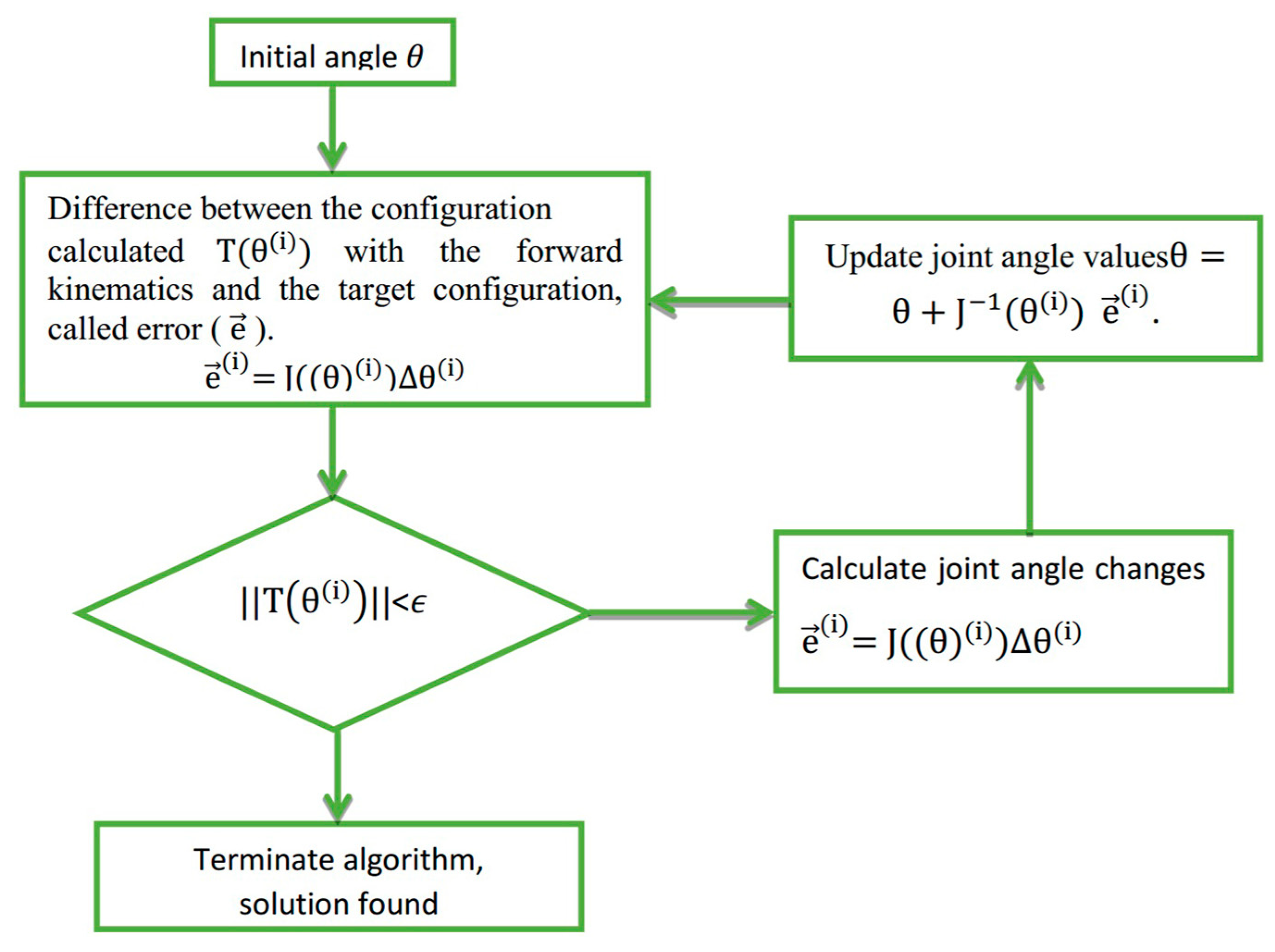
3.2.2. Inverse Kinematics

The process of solving inverse kinematics for continuum robots is inherently challenging. In the case of continuum robots with constant curvature (CC), the initial step typically involves establishing an inverse mapping, known as the robot-independent inverse mapping, between the task space and the configuration space. This mapping is aimed at determining the arc parameters that govern various segments of the robot, ultimately aligning them with the desired tip orientation [61]. However, when dealing with continuum robots featuring numerous cross-sections, obtaining all conceivable solutions can be a complex task. To address this, three commonly used methods have emerged.
The conventional approach to solving inverse kinematics for continuum robots involves the Jacobian matrix pseudo-inverse method [71,72,73,74,75]. Notably, the Jacobian matrix is a square matrix, rendering it suitable primarily for 6-DOF manipulators [76,77]. When applied to continuum robots characterized by non-square or less than full-row rank Jacobians, such as those with continuous deformations, the conventional Jacobian method becomes less applicable [78]. To address this challenge, a pseudo-inverse method is introduced, replacing the Jacobian inverse matrix with a pseudo-inverse Jacobian matrix. It should be noted that pseudo-inverse matrices are approximations to inverse matrices, not exact equivalents. The solution to inverse kinematics in the pseudo-inverse method is represented as
Δ θ = J Δ x
where Δ θ denotes the incremental joint angles, and Δ x signifies the incremental end-effector pose. The pseudo-inverse matrix, J , is derived as J = J T J J T 1 . This approach transforms the continuum robot into a rigid body model and utilizes an iterative process based on the Jacobian pseudo-inverse matrix [79]. Nonetheless, this method exhibits stability issues near singularities [80] and introduces iteration errors due to the approximative nature of the solutions.
In 2009, Srinivas Neppalli et al. [81] proposed a closed-form geometric approach that is applicable to both single and multiple cross-sections. This method relies on modeling each section using spherical joints and straight rigid linkages, subsequently applying an analytical procedure to solve the inverse kinematics for the model before converting the results back into arc parameters. While this approach provides access to the entire solution space of rigid link robots and can be easily adapted to n-link robots, it does not account for certain physical constraints, such as limited actuator length, force, or position.
The finite element method is another technique used for solving inverse kinematics. This method involves establishing a model based on geometric relationships, providing a set of initial solutions, and iteratively computing joint angles until the desired pose is achieved [79,82]. The classical iterative method often employed in this context is the Newton–Raphson method [83], known for its high iteration accuracy. However, it relies heavily on the initial selection of end-effector values, making it susceptible to instability [84]. A diagram of the Newton–Raphson algorithm is provided in Figure 16 [85]. Given the initial joint angle, the pose is calculated based on the forward kinematics. Compared with the target pose, the error between them is calculated. If the error is greater than the allowable error tolerance, the Jacobian matrix is used to calculate the joint angle change and update the joint angle. The iteration will be repeated until the error is less than the allowable tolerance.
In addition to the aforementioned methods, neural networks [86,87,88] have also been explored for solving inverse solutions of continuum robots. These networks find applications in the control and modeling of continuum robots. However, in cases where the robot possesses a high number of DOF, extensive computation may be required due to the size of the training dataset [79].

3.3. Dynamics Modelling

In general, the deformation of a continuum robot can be accurately described by kinematics under typical operating conditions. However, when external factors introduce interference, or when the robot operates at high speeds, the kinematic model may fall short of accurately representing the dynamic deformation process. In earlier studies dating back to 1994, dynamics models for continuum robots were approximated using principles from continuum mechanics [89]. Despite this method’s approximation, it produced expressions that could be efficiently computed in a highly parallel manner, irrespective of the number of DOF. The accuracy of this approach was confirmed through comparisons with the Lagrange formula for the dynamics of lumped mass manipulators.
In contrast to the advances in kinematic modeling, progress in dynamic modeling has been relatively slow. Since the 2010s, Cosserat rod models [90] have been widely applied for the dynamics analysis of single-segment manipulators [41] and multi-segment manipulators [91]. Geometrically accurate models based on Cosserat bar theory have demonstrated the ability to represent significant deformations, including bending, torsion, shear, and tensile deformations [90]. In the context of CDCRs, the Kirchhoff model, a subset of the Cosserat model, is commonly employed. It specifically addresses bending and torsional motions while excluding shear and extension in the Cosserat bar model [92,93]. The in-depth exploration of the classical Cosserat rod model is illustrated in Antman’s [90] comprehensive work on nonlinear elasticity, which employs symbols and mathematical terms familiar to roboticists [65]. Here, a brief introduction is provided: a bar with a cross-sectional area a , mass density ρ , and second bending moment area j is subjected to internal forces n and internal bending moments m , as well as distributed forces f ( σ ) and distributed bending moments l ( σ ) , and inertial forces p ¨ due to acceleration (all represented in the global frame). This is depicted in Figure 17 [94]. The equilibrium equation for the infinitesimal segment of the Cosserat rod, defined by σ [ c ,   s ] (with boundary points defined by the arc length coordinates c and s ), can be expressed as
n s + f s = ρ a p ¨
The moment balance is expressed as
m s + p s × n s + l s = j ω ˙
The above equations present a boundary value problem where the fundamental configuration and top loading conditions are known. Both dynamic and static solutions necessitate the use of numerical integration techniques and gradient-based solvers. Challenges arise from the presence of fast oscillation modes that require fine temporal integration steps and large deformation modes demanding fine spatial integration steps [95]. As a result, real-time implementation of Cosserat rod dynamics may not be suitable for tasks such as online simulation or controller design, being better suited for general continuum robot simulations in the presence of friction and external loads [96]. An alternative approach to tackle this issue is by implicitly discretizing the time derivative, effectively resolving it with each time step as an arc length s [92,97]. Incorporating the Cosserat rod method into the controller design framework is not a straightforward endeavor but can be achieved through the optimization of inverse system mechanics [41] or continuous system control theory.
Discrete and modal kinematics can simplify a continuous system into equivalent finite state rigid or flexible counterparts, such as multiple moving platform (arm disc) units, so as to achieve the approximation of geometrically accurate solutions of rod-driven continuum robots. The dynamic equation of the manipulator can be obtained by integrating multiple arm disks with the mass matrix and stiffness matrix of the arm disks. Early studies focused on spatial dynamics modeling for single-segment manipulators [98] and planar modeling for multi-segment manipulators [99,100]. For manipulators comprising multiple joint modules, recursive algorithms for spatial modeling [101], also known as inverse Newton–Euler algorithms, inverse dynamics models, or reduced integrals [102,103,104], were developed. The system’s equation of motion (EoM) is derived by understanding the kinematic relations and dynamic interactions between the components of the system. This process involves a step-by-step derivation method that generates a large number of modeled states, including internal forces. More recently, researchers have achieved dynamic models of segmented continuous manipulators with constant curvature (CC) through modal transformation and system Lagrange, based on kinetic and potential energy of elements [101,105,106], or the principle of virtual work (PVW) (Kane’s method), based on the virtual displacement of elements [43,107]. These methods offer the advantage of limiting the number of independent states (generalized coordinates), although they require extensive study for controller design. Their disadvantages include the complexity of the final equations, making interpretation challenging, and the need to address nonlinear elastic and damping elements [108]. In essence, these models are well-suited for simulation purposes but may not be ideal for model-based control design [96].
As a result, an additional step is typically necessary to consolidate the final EoM into a closed-form vector framework. The transformed mass matrix technique (TMT) method, named by Schwab et al. [109], is based on elements of Lagrange’s analytical mechanics. It involves generalized coordinates, virtual work, and inertial forces, ultimately projecting the system’s inertia matrix M into the state space T T M T (generalized coordinate space) using the spatial transformation Jacobian matrix T . This technique eliminates higher derivatives in the derivation process, directly deriving the EoM in a closed vector form. The derived terms are independent, making them suitable for parallel numerical evaluation, and the final EoM form is straightforward to interpret, facilitating controller design [108]. In comparison to the Lagrange method, it generates system dynamics in a PVW-based vector form with fewer derivation steps [108,110,111]. The finite-state system produced is computationally less complex than Cosserat bar dynamics and is compatible with nonlinear control design techniques for rigid bodies. However, the EoM’s accuracy may be reduced due to potential approximate kinematics, time-stepping issues, and complex derivations prone to numerical instability [95]. These challenges can be addressed through finite element summation fitting [108].
In summary, three key challenges are evident: Firstly, while kinematic modeling based on CC methods provides relatively high precision, the accuracy of the backbone model is often insufficient, making it challenging to realize a true CC model. Secondly, modeling based on variable curvature (VC) methods can be demanding. Even if high-precision modeling is achieved, it can be difficult to attain high-precision control for the pose required by researchers. Finally, there is a shortage of efficient dynamic modeling methods. Therefore, if the piecewise constant curvature assumption is adopted as the premise, the curvature consistency of the skeleton should be guaranteed. Hence, strengthening the load capacity of the skeleton and solving the S-shape deformation will be the focus of future modeling research. This approach promises to improve modeling accuracy and facilitate subsequent control, albeit potentially at the cost of some flexibility.

4. CDCR Motion Planning

Upon completing the kinematic and dynamic analysis of CDCRs, the next essential step is motion planning. This phase is critical for achieving safe, efficient, and reliable robot motion. Motion planning for continuum robots is built on the foundations of path planning and trajectory planning [112]. Path planning focuses on defining a sequence of path points connecting two locations, A and B, based solely on geometric parameters and independent of time considerations. In contrast, trajectory planning enhances path planning by incorporating time-related information. It is particularly concerned with aspects such as displacement, velocity, and acceleration of robotic motion, with the objective of ensuring smooth motion profiles and controlled motion speeds [113]. Generally, trajectory planning primarily focuses on the end of the manipulator.
Motion planning encompasses the determination of suitable trajectories and action sequences through algorithmic and strategic approaches. This process is essential for guiding the robot in achieving specific goals or tasks. It encompasses considerations such as the initial state, target state, motion constraints, environmental information, and the selection of an appropriate path and action sequence to accomplish the desired motion. Notably, in the context of CDCRs, motion planning is not limited to planning for the end effector alone; it also encompasses planning for the entire backbone.
In cases where obstacles are present within a continuum robot’s workspace, motion planning is crucial for charting collision-free paths that allow the robot to reach predefined poses and complete its tasks. Avoiding collisions with obstacles is the foundational requirement of motion planning for continuum robots. Additionally, in the process of transitioning between different attitudes, optimal paths and action sequences are selected to minimize specific criteria, such as time, energy consumption, or distance. This optimization enhances motion efficiency and robot performance, constituting the second requirement of motion planning. Furthermore, motion planning must account for dynamic constraints inherent to CDCRs. It involves selecting suitable paths or action sequences to ensure smooth and stable movement that adheres to the robot’s motion capabilities. Finally, the ultimate objective is to achieve broader mission goals, such as navigating pipelines, performing medical surgeries, engaging in exploration and rescue missions, and more.
During the execution of operational tasks, CDCRs face varying obstacle distributions within their environments. These scenarios can generally be classified into three categories based on the obstacle density:
  • Tunnel type: In this scenario, obstacles are densely distributed, and the feasible workspace for the manipulator resembles a pipeline. This configuration is particularly suitable for applications in fields such as pipeline cleaning, endoscopic surgery in the human large intestine, and internal maintenance of aerospace engines, all of which require minimal invasion.
  • Scattered obstacle type: Obstacles are dispersed throughout the workspace in the form of objects or surfaces. This situation is found in tasks involving narrow openings (e.g., firefighting through narrow doors and windows), automatic object retrieval from supermarket shelves (unmanned supermarkets), and similar contexts.
  • Barrier-free: This scenario involves no obstacles in the workspace, allowing the manipulator to reach its target position freely. It is encountered in settings like underwater environments (cleaning underwater cages), routine tasks (object manipulation, desktop writing, posture teaching), and more.
The distribution of obstacles in the environment, in combination with the manipulator’s specific configuration (e.g., fixed base on a straight slide rail or a manipulator fixed on a 6-DOF platform), results in different motion planning approaches. Researchers typically develop distinct motion planning schemes tailored to each of these situations.
In summary, overcoming the most challenging scenarios paves the way for solving simpler problems. For instance, if a CDCR can navigate a tunnel-type obstacle, it becomes more straightforward to address scenarios with scattered obstacles, and even cases with no obstacles. Indeed, most researchers choose to develop motion planning algorithms starting from situations with the highest obstacle density. Traversing tunnel-type obstacles poses the primary challenge of maintaining the body’s shape along the path while moving the robot’s tip to a new position [21].

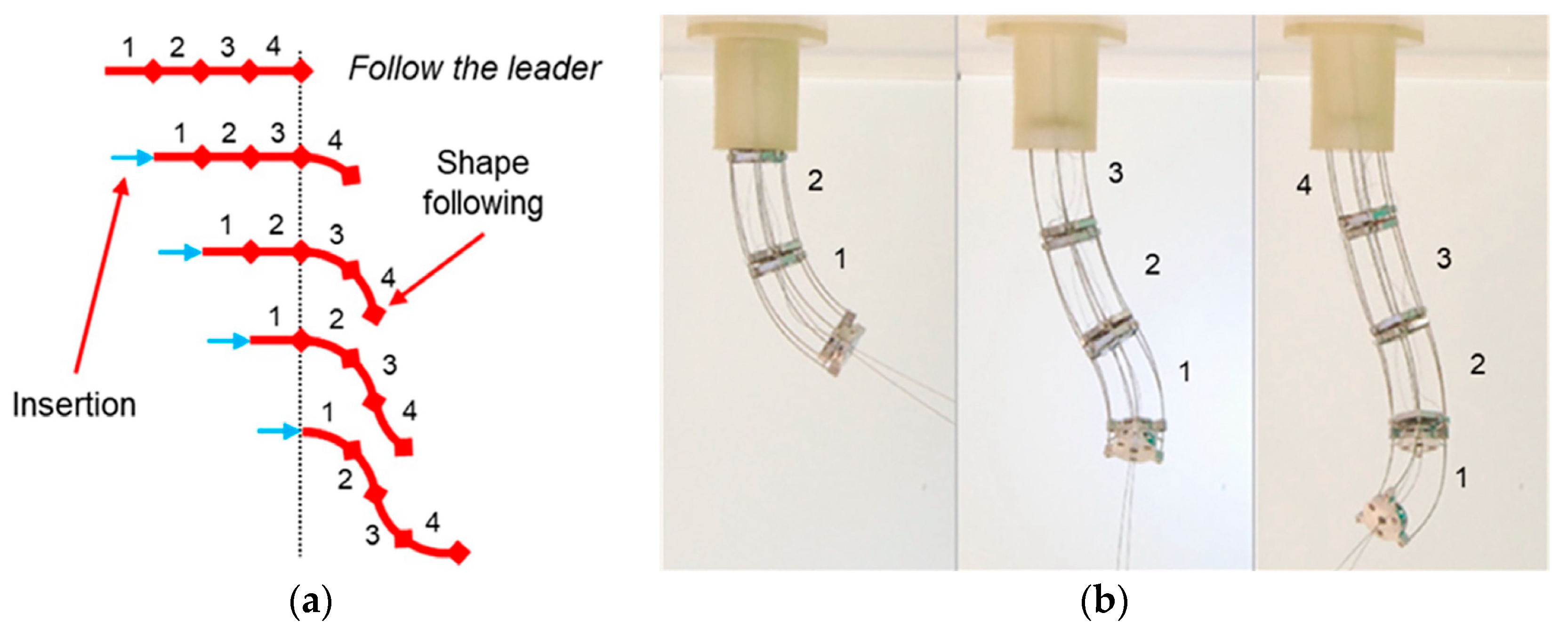
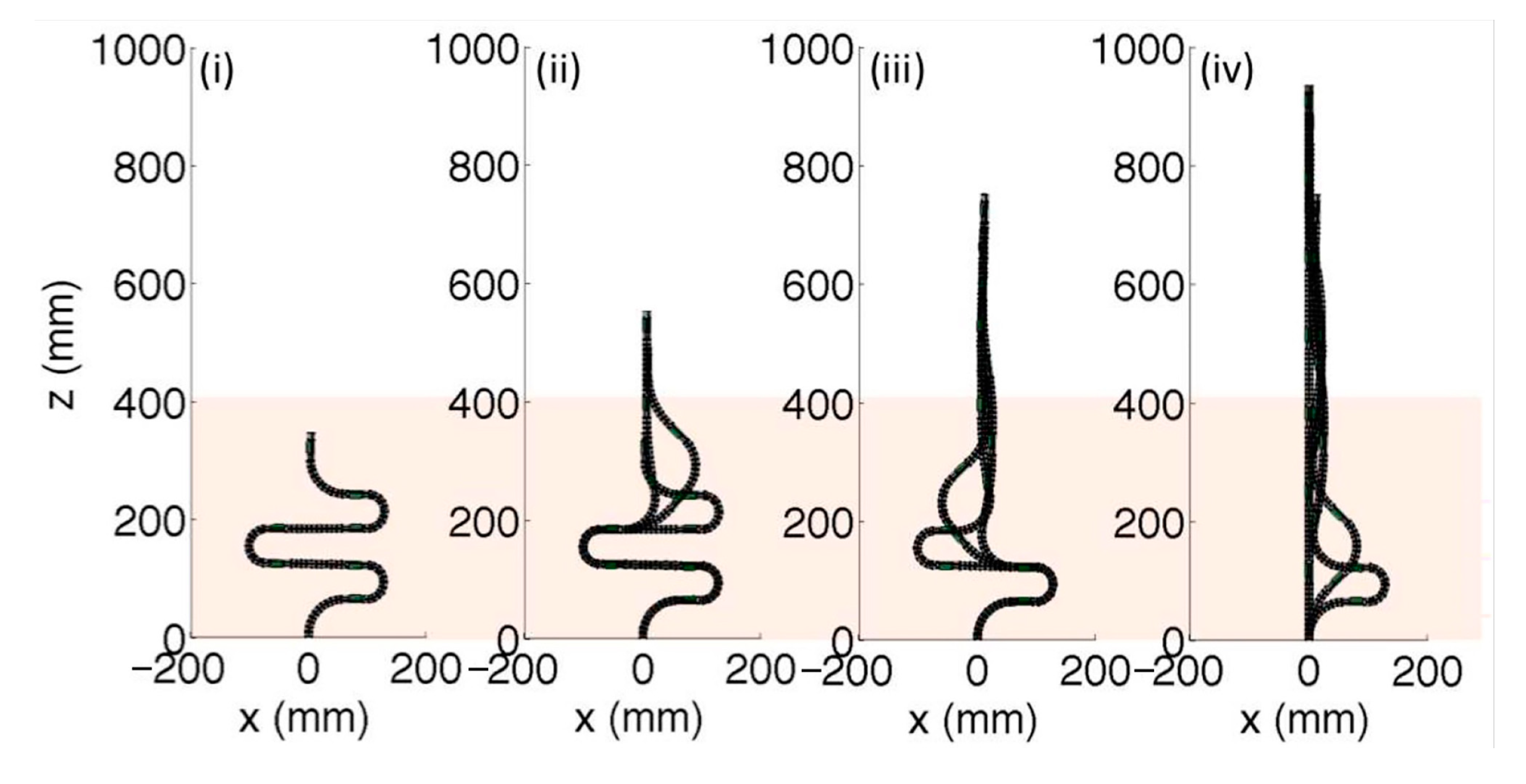
4.1. Follow-the-Leader (FTL) Method

The follow-the-leader (FTL) method has emerged as a prominent motion planning technique over the past few decades and is widely employed in various applications. It necessitates that the robot’s shape remains consistent with the path guided by its tip and is continually maintained (as depicted in Figure 18) [114,115]. Various incarnations of FTL methods exist, contingent upon the underlying assumptions related to the robotic backbone.
In the case of CDCRs based on a segmented variable curvature (VC) backbone, the section-wise FTL method is often employed. This technique propels the continuum robot in discrete steps, with the furthest part advancing to a new position while each subsequent arm disc joint module maintains the position of the previous module [114,116]. This strategy is reminiscent of the principles seen in the classic “snake game.” While simple and effective, this method is constrained by the length of movement, and it necessitates that the joint modules of the manipulator have identical lengths. It’s important to note that achieving “perfect” lead following is contingent on the current advancement length being an exact multiple of the joint module length, a condition that can be challenging to meet in most scenarios, necessitating careful planning for transitioning between configurations [21].
In contrast, the continuous FTL method is based on the Cosserat model, which describes the shape of the backbone using the time-varying arc length, denoted as g ( s , t ) S E ( 3 ) , representing the centerline position, p ( s , t ) R 3 , and the disk orientation, R ( s , t ) S O ( 3 ) , with respect to the arc length s [ 0 , l ( t ) ] along the centerline. The parameters s and t are considered independent of each other and assumed to be symmetric in mixed partial derivatives concerning s and t . The length function, l ( t ) , varies over time and signifies the exposed length of the robot, i.e., the length inserted into the workspace, as opposed to the full length of the robot. The evolution of the transformation g ( s , t ) can be described by the following motion differential equation:
g s , t = g s , t s = g s , t ξ ^ s , t
where ξ ^ ( s , t ) corresponds to the Lie algebra s e ( 3 ) , associated with the vector ξ R 6 , which resides in the twist coordinates ξ ( s , t ) = [ v ( s , t ) T u ( s , t ) T ] T of the body frame. The transformation component is defined as
R s , t = R s = R s , t u ^ s , t
p s , t = p s = R s , t v s , t
When the z-axis z ( s , t ) of R ( s , t ) aligns with the curve’s tangent, the expression can be further reduced to p ( s , t ) = z ( s , t ) . Additionally, it is assumed that at the insertion point of the robot, s = 0 , the rotation and position remain fixed at R ( 0 , t ) = R z ( φ 0 ( t ) ) and p ( 0 , t ) = 0 . In continuous FTL, the position of any point along the curve does not change with time [117], and this condition is expressed as
p ˙ ( s , t ) = p ( s , t ) s = 0
where the   p ˙ represents the partial derivative of the center line position with respect to time. Although this approach provides a geometrically precise solution for CDCRs, it does not account for the discrete nature of modular rigid arm disks. Moreover, challenges related to convergence and stability limit the practical applicability of this model [21].

4.2. Coiling Method

The FTL method has been proven effective in addressing the tunnel obstacle distribution problem. Therefore, the coiling method may be more suitable for the remaining two cases [95]. In nature, it has often been observed that certain plants’ vines [118] display a circular coiling pattern [119], as illustrated in Figure 19 [120]. This behavior offers several advantages, such as enhancing the likelihood of effective contact with support structures in an open environment through coiling [121] and facilitating upward growth [122]. It also improves the ability to withstand external interference and load capacity [123]. Multi-circle coiling, resembling a spring, effectively distributes external forces evenly across various segments, reducing the forces experienced by each segment compared to a straight backbone. This structural design enhances penetration [124]. Besides circular coiling, there is a preceding S-shaped coiling. This method enables rapid movement by simultaneously releasing energy through various curved segments. The realm of biology inspires many recent continuum robot designs and motion strategies [121]. Researchers have effectively applied coiling properties to the motion planning of CDCRs.
In scenarios where the robot’s base is fixed and it needs to grasp objects near the base, control over the distance between the robot’s ends is achieved by altering the number of coiling circles or the degree (radius) of coiling, as depicted in Figure 19 [120,123,125]. If the target object is located at a considerable distance, the robot can use coiling to support itself on obstacles along the path [126,127]. This ensures that the slender CDCRs do not unnecessarily bend or sag due to inadequate structural support, its weight, or external loads. In situations where the robot’s base is fixed and it needs to pass through openings near the end of the base, open-loop movement through segmented S-coiling, as displayed in Figure 20 [128], is an effective approach. The robot progressively unwinds the S-coiling to advance. This uncoiling effect, illustrated in Figure 19, allows the robot to unfold in narrow spaces and enhance its navigational capabilities [21]. Active uncoiling can be achieved by computing an optimal trajectory that minimizes displacement [129].

4.3. Sensing-Based Navigation

When CDCRs are employed to perform tasks in unstructured environments such as gastroenteric operations or cave rescue missions, sensing-based navigation is essential for a CDCR to move from starting position to goal position. Utilizing various sensors, a sensing-based navigation system provides the necessary environment information as well as the CDCR state for localization and mapping. For CDCRs, there exist two major categories of sensing techniques, i.e., self-sensing and environmental sensing.
The self-sensing techniques are mainly employed to measure the shape change of a CDCR, which can be classified into the following approaches: (1) vision-based motion capture system for an open and barrier-free environment [130,131]; (2) stretchable sensors arranged along the backbone of a CDCR for an indirect measurement through kinematic mapping [132]; (3) magnetic sensors integrated into a CDCR to estimate its shape changes [133,134]; (4) fiber Bragg grating (FBG) sensors to measure bending of a CDCR’s backbone [95,135,136,137,138,139]. In general, the existing self-sensing techniques only allow for imprecise measurement of the CDCRs shape due to the high flexibility and large deflection of the CDCR’s backbone as well as the unknown external loads and disturbances. It is still a challenging issue to develop precise and reliable self-sensing technique for CDCRs.
The environmental sensing techniques are mainly employed for mapping and object understanding, which can be classified into the following approaches: (1) visual sensing with high-resolution cameras for non-contact exploration and mapping of the CDCR’s workspaces [140,141]; (2) tactile sensing with capacitive and resistive sensors for a CDCR to “feel” and understand its surrounding objects during interaction [142,143,144,145,146]; (3) contact force sensing with an integrated force-torque sensor mounted onto the CDCR’s tip to measure the contact force [147]. Among the environmental sensing techniques, to develop high-fidelity, high-flexibility, and high-reliability electronic skins is promising for tactile sensing.
In actual application scenarios, CDCRs often encounter more complex environments. Hence, researchers must judiciously combine or sequentially employ various motion planning schemes. Presently, the foremost challenge in motion planning for rod-driven continuum robots is the delicate balance between the desired optimal pose and what the robot can realistically achieve, constrained by the robot joint lengths. One possible solution is to build a repulsive force field around the obstacle (which can be equivalent to a curve with no radius for the robot) while building a gravitational field at the target location [148]. According to the minimum superposition value of obstacle and target pose, the robot trajectory is selected. In addition, the skeleton of most rope-driven continuous robot has a large rebound ability in order to ensure the stiffness. To avoid excessive internal forces, it is necessary to follow the goal of minimizing the degree of curvature of each joint. In the future, following optimizations to the robot’s configuration and driving modes, the potential for true continuous motion may become attainable.

5. CDCR Motion Control

Robot control involves the study of determining the precise actuation required to achieve the desired state for executing a given task. The state of a CDCR encompasses various aspects, including the position and orientation of the end effector, the robot’s configuration, its stiffness, and related motion performance [18]. In contrast to rigid robots, the control of CDCRs presents additional challenges, such as dealing with redundant DOF, cable deformation due to tension, and S-shaped deformation of the robot’s backbone [149,150]. The essence of motion control lies in efficiently attaining the desired robot state under these unique conditions. Existing control methods can be classified into three categories based on robot modeling techniques: model-based control [151], model-free control, and hybrid control [152].

5.1. Model-Based Control

Model-based control necessitates the consideration of the mapping between the actuation space, joint space, and task space. To achieve effective control, enhancing the accuracy of the robot model is often required (specifically, improving the robot’s configuration accuracy within the piecewise constant curvature model). Taking the VC model as an example, drive feedback and attitude feedback are employed to mitigate model errors and enhance real-time control accuracy, including encoders, torque sensors, electromagnetic sensors [153,154], analytical calculation [155], visual feedback [156,157], flexible sensors, etc. Drive feedback assists in tracking and compensating for errors related to actuator joints (e.g., cable friction, coupling, hysteresis [95]). Attitude feedback allows the task space controller to directly influence the robot’s moving target, providing robustness against model uncertainty. It is noteworthy that, compared to low-level control systems in the actuation space, control systems in the joint space tend to be more stable, facilitating higher frequencies and better dynamic performance [158].
Reference control strategies include closed-loop control based on real-time Cosserat bar theory [159], the generalized force method [160], the extended Kalman filter method [41], and recursive linear estimation techniques [161]. In summary, model-based control methods offer relatively high control accuracy and stability during low-frequency motions and closed-loop feedback [162,163,164,165]. Nevertheless, unknown constraints and environmental obstacles (e.g., contact constraints) introduce uncertainty into the control of continuum robots [166,167]. In constrained environments, the model-based Jacobian determinants may become inaccurate due to the potential uncontrollable DOF arising from the CDCR’s backbone [166]. In addition, obtaining attitude feedback for small CDCRs can be challenging. Firstly, limitations arise due to size (integrating sensors can be problematic), and secondly, practical applications, such as endoscopic surgical robots, make it challenging to acquire external visual feedback [18,154,168]. It is evident that addressing the issue of model inaccuracies stemming from contact constraints or limited feedback poses a significant challenge in model-based control methods.

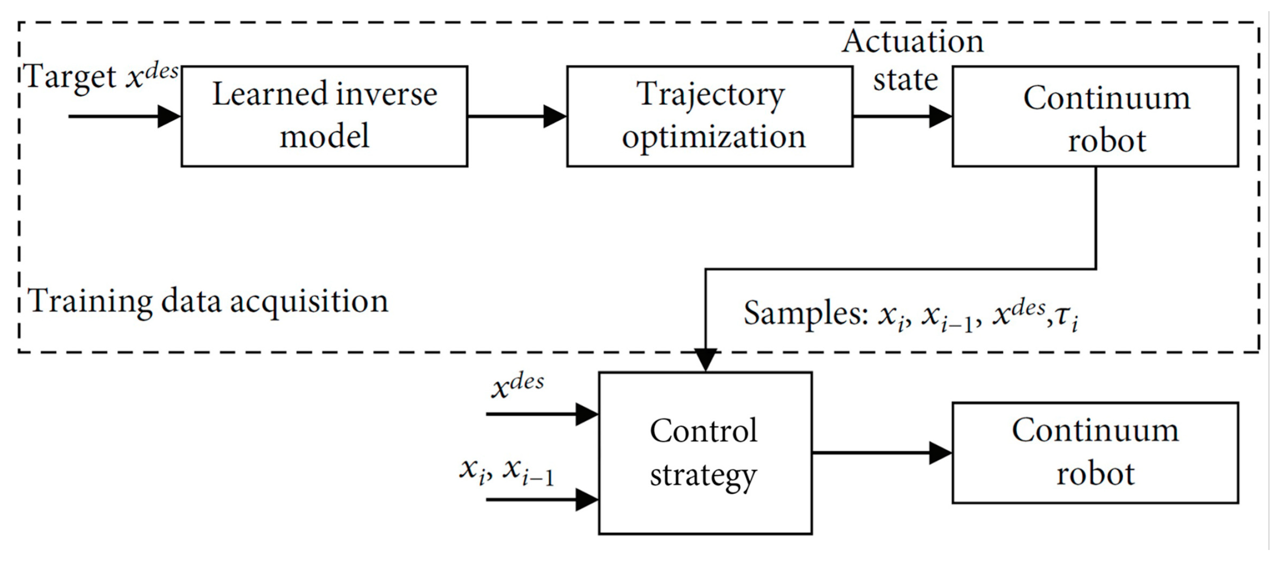
5.2. Model-Free Control

Model-free approaches (as depicted in Figure 21) offer a solution to circumvent the complexities of using intricate kinematic and dynamic models of manipulators, along with the need for precise calibration. These approaches rely on data-driven techniques, such as machine learning and empirical methods, making them an effective alternative. They operate independently of joint space and can provide robust and stable performance, particularly when model-based methods face challenges like highly nonlinear systems or unstructured environments [169].
Reference control strategies encompass Jacobian empirical estimates [166], as well as strategies based on learning techniques [170,171,172,173,174,175]. However, the data-driven approach is still relatively more abstract in its presentation of the problem because it is not as reliable as model-based control methods for operations that require precision and safety, such as surgery. Moreover, model-free methods often involve lengthy computation times, limited adaptability to changes in the environment, and complex learning processes [18].

5.3. Hybrid Control

Given the uniqueness of each robotic structure and the discrepancies between drive and model descriptions, the adaptability of different continuum robot structures poses added challenges for learning methods. Hybrid model control, illustrated in Figure 22, strikes a balance between the reliability of model-based control and the robustness of data-driven approaches [18]. This approach integrates model-based and model-free methods at different kinematic layers [158] or employs models to guide the learning process [151].
Reference control strategies include the hybrid adaptive control framework [176] and control methods based on the Koopman operator theory [177,178]. Experimental results indicate that the hybrid control method effectively compensates for uncertain factors, such as friction, driving tendon relaxation, and external loads during robot motion [18]. It also addresses the ambiguity in selecting discrete state sets for structures with infinite DOF [177].
The three aforementioned motion control methods underscore researchers’ commitment to enhancing the accuracy of continuum robot models and achieving precise target poses. However, they appear to overlook the potential limitations in realizing the desired high-precision model and full-arm attitude control from the base end. Contact constraints in the environment introduce uncertainty into the robot model, even with feedback control, leading to the likelihood that the robot’s configuration may not reach the expected shape. Hence, the primary challenge at present lies in the conflict between increasingly accurate models and severely limited driving DOF.
For CDCRs, two potential paths emerge. The first involves sacrificing some flexibility to address the S-shaped deformation issue, improving the accuracy of the backbone model based on the piecewise constant curvature assumption, and focusing on enhancing control accuracy. The second path involves maximizing the flexibility of CDCRs based on the VC model. In this approach, the robot’s arrival pose is sensed through a robust feedback system, and potential motion poses under various loads are predicted using a powerful learning system. However, this approach may sacrifice control precision and limit the robot’s ability to perform common tasks in human society. Achieving a balance between these two paths is essential, with variable stiffness control playing a pivotal role.

6. Conclusions

This study has provided a comprehensive review of the progress in the configuration design, kinematics and dynamics modeling, motion planning, and motion control of CDCRs, highlighting several notable achievements in the field. Our aim is to offer clarity and a more comprehensive understanding for researchers working in this domain. Despite the considerable research efforts dedicated to CDCRs, this technology is still in its nascent stages, with rare or nonexistent appearances at industry exhibitions. This underscores the fact that CDCRs have yet to find their way into industrial applications or everyday life.
Throughout this review, we have underscored the limitations and challenges faced by CDCRs across various aspects. In response, we have suggested reasonable solutions and directions for future development. In summary, the advancement of CDCRs is imperative for enhancing their performance and expanding their utility, thereby unlocking their tremendous potential for applications in emerging fields. Such progress would signify a significant leap forward, taking robots from mere precision and efficiency to a realm of intelligence and dexterity, heralding a promising future for the field of robotics.

Author Contributions

Conceptualization, H.B., B.G.L. and G.Y.; methodology, H.B.; validation, H.B., W.S. and H.Z.; formal analysis, H.B. and W.S.; investigation, H.B., S.Q. and J.Z.; resources, all; data curation, H.B. and B.Y.; writing—original draft preparation, H.B.; writing—review and editing, H.B., B.G.L. and G.Y.; visualization, H.B.; supervision, G.Y., B.G.L., S.Y. and L.H.; project administration, G.Y., B.G.L., Z.F. and T.Z.; funding acquisition, G.Y. All authors have read and agreed to the published version of the manuscript.

Funding

This research was funded by National Natural Science Foundation of China (U1909215, 92048201, 52127803, and U21A20121), the Zhejiang Provincial Key Research and Development Plan (2023C01176 and LD22E050007).

Data Availability Statement

Not applicable.

Acknowledgments

This work was supported by the Ningbo Institute of Materials Technology and Engineering, Chinese Academy of Sciences, China.

Conflicts of Interest

The authors declare no conflicts of interest.

References

  1. Villani, V.; Pini, F.; Leali, F.; Secchi, C. Survey on human–robot collaboration in industrial settings: Safety, intuitive interfaces and applications. Mechatronics 2018, 55, 248–266. [Google Scholar] [CrossRef]
  2. IFR International Federation of Robotics. Executive Summary World Robotics 2016 Industrial Robots; IFR International Federation of Robotics: Frankfurt, Germany, 2016. [Google Scholar]
  3. Matheson, E.; Minto, R.; Zampieri, E.G.G.; Faccio, M.; Rosati, G. Human–Robot Collaboration in Manufacturing Applications: A Review. Robotics 2019, 8, 100. [Google Scholar] [CrossRef]
  4. Walker, I.D. Continuous Backbone “Continuum” Robot Manipulators. ISRN Robot. 2013, 2013, 726506. [Google Scholar] [CrossRef]
  5. Liu, J.; Li, P.; Zuo, S. Actuation and design innovations in earthworm-inspired soft robots: A review. Front. Bioeng. Biotechnol. 2023, 11, 1088105. [Google Scholar] [CrossRef]
  6. Tavsan, F.; Sonmez, E. Biomimicry in Furniture Design. Procedia Soc. Behav. Sci. 2015, 197, 2285–2292. [Google Scholar] [CrossRef]
  7. Rus, D.; Tolley, M.T. Design, fabrication and control of soft robots. Nature 2015, 521, 467–475. [Google Scholar] [CrossRef]
  8. Anderson, V.C.; Horn, R.C. Tensor Arm Manipulator Design. Trans Asme. 1967, 67, 1–12. [Google Scholar]
  9. Robinson, G.; Davies, J.B.C. Continuum Robots: A State of the Art. In Proceedings of the IEEE International Conference on Robotics and Automation, Detroit, MI, USA, 10–15 May 1999. [Google Scholar]
  10. Kumar Singh, P.; Krishna, C.M. Continuum Arm Robotic Manipulator: A Review. Univers. J. Mech. Eng. 2014, 2, 193–198. [Google Scholar] [CrossRef]
  11. Hannan, M.W.; Walker, I.D. Analysis and experiments with an elephant’s trunk robot. Adv Robot 2001, 15, 847–858. [Google Scholar] [CrossRef] [PubMed]
  12. Chirikjian, G.S. Theory and Applications of Hyper-Redundant Robotic Manipulators; California Institute of Technology: Pasadena, CA, USA, 1992. [Google Scholar]
  13. Hannan, M.W.; Walker, I.D. Kinematics and the Implementation of an Elephant’s Trunk Manipulator and Other Continuum Style Robots. J. Robot. Syst. 2003, 20, 45–63. [Google Scholar] [CrossRef] [PubMed]
  14. Laschi, C.; Cianchetti, M.; Mazzolai, B.; Margheri, L.; Follador, M.; Dario, P. Soft Robot Arm Inspired by the Octopus. Adv. Robot. 2012, 26, 709–727. [Google Scholar] [CrossRef]
  15. Kier, W.M.; Smith, K.K. Tongues, tentacles and trunks: The biomechanics of movement in muscular-hydrostats. Zool. J. Linn. Soc. 1985, 83, 307–324. [Google Scholar] [CrossRef]
  16. Wilson, J.F.; Mahajan, U.; Wainwright, S.A.; Croner, L.J. A continuum model of elephant trunks. J. Biomech. Eng. 1991, 113, 79–84. [Google Scholar] [CrossRef] [PubMed]
  17. Chopin, R. What is a Continuum Robot. Available online: https://www.zhihu.com/question/452689468/answer/2623665287 (accessed on 12 August 2022).
  18. Zhang, J.; Fang, Q.; Xiang, P.; Sun, D.; Xue, Y.; Jin, R.; Qiu, K.; Xiong, R.; Wang, Y.; Lu, H. A Survey on Design, Actuation, Modeling, and Control of Continuum Robot. Cyborg Bionic Syst. 2022, 2022, 9754697. [Google Scholar] [CrossRef]
  19. Hirayama, A.; Ito, K. Development of rescue manipulator to search narrow space for victims. Artif. Life Robot. 2008, 13, 331–335. [Google Scholar] [CrossRef]
  20. Bishop, C.; Russo, M.; Dong, X.; Axinte, D.A. A Novel Underactuated Continuum Robot With Shape Memory Alloy Clutches. IEEE/ASME Trans. Mechatron. 2022, 27, 5339–5350. [Google Scholar] [CrossRef]
  21. Mohammad, A.; Russo, M.; Fang, Y.; Dong, X.; Axinte, D.A.; Kell, J. An Efficient Follow-the-Leader Strategy for Continuum Robot Navigation and Coiling. IEEE Robot. Autom. Lett. 2021, 6, 7493–7500. [Google Scholar] [CrossRef]
  22. Simaan, N.; Xu, K.; Kapoor, A.; Wei, W.; Kazanzides, P.; Flint, P.; Taylor, R. Design and Integration of a Telerobotic System for Minimally Invasive Surgery of the Throat. Int. J. Rob. Res. 2009, 28, 1134–1153. [Google Scholar] [CrossRef]
  23. Li, Z.; Du, R. Design and Analysis of a Bio-Inspired Wire-Driven Multi-Section Flexible Robot. Int. J. Adv. Robot. Syst. 2013, 10, 209. [Google Scholar] [CrossRef]
  24. Ahmed, F.; Waqas, M.; Jawed, B.; Soomro, A.M.; Kumar, S.; Hina, A.; Khan, U.; Kim, K.H.; Choi, K.H. Decade of bio-inspired soft robots: A review. Smart Mater. Struct. 2022, 31, 073002. [Google Scholar] [CrossRef]
  25. Greer, J.D.; Morimoto, T.K.; Okamura, A.M.; Hawkes, E.W. Series pneumatic artificial muscles (sPAMs) and application to a soft continuum robot. In Proceedings of the 2017 IEEE International Conference on Robotics and Automation (ICRA), Singapore, 29 May–3 June 2017; pp. 5503–5510. [Google Scholar]
  26. Farrow, N.; Correll, N. A soft pneumatic actuator that can sense grasp and touch. In Proceedings of the 2015 IEEE/RSJ International Conference on Intelligent Robots and Systems (IROS), Hamburg, Germany, 28 September–2 October 2015; pp. 2317–2323. [Google Scholar]
  27. McMahan, W.; Chitrakaran, V.K.; Csencsits, M.A.; Dawson, D.M.; Walker, I.D.; Jones, B.A.; Pritts, M.B.; Dienno, D.; Grissom, M.D.; Rahn, C.D. Field trials and testing of the OctArm continuum manipulator. In Proceedings of the 2006 IEEE International Conference on Robotics and Automation, 2006, ICRA 2006, Orlando, FL, USA, 15–19 May 2006; pp. 2336–2341. [Google Scholar]
  28. Mohd Jani, J.; Leary, M.; Subic, A.; Gibson, M.A. A review of shape memory alloy research, applications and opportunities. Mater. Des. 2014, 56, 1078–1113. [Google Scholar] [CrossRef]
  29. Zheng, T.; Yang, Y.; Branson, D.T.; Kang, R.; Guglielmino, E.; Cianchetti, M.; Caldwell, D.G.; Yang, G. Control design of shape memory alloy based multi-arm continuum robot inspired by octopus. In Proceedings of the 2014 9th IEEE Conference on Industrial Electronics and Applications, Hangzhou, China, 9–11 June 2014; pp. 1108–1113. [Google Scholar]
  30. Mandolino, M.A.; Goergen, Y.; Motzki, P.; Rizzello, G. Design and Characterization of a Fully Integrated Continuum Robot Actuated by Shape Memory Alloy Wires. In Proceedings of the 2022 IEEE 17th International Conference on Advanced Motion Control (AMC), Padova, Italy, 18–20 February 2022; pp. 6–11. [Google Scholar]
  31. Hu, H. Kinematic Analysis and Simulation for Cable-driven Continuum Robot. J. Mech. Eng. 2010, 46, 1–8. [Google Scholar] [CrossRef]
  32. Shen, W.; Yang, G.; Zheng, T.; Wang, Y.; Yang, K.; Fang, Z.; Zhang, C. An Integrated Accuracy Enhancement Method for Cable-driven Flexible Continuum Robot. In Proceedings of the 2019 IEEE/ASME International Conference on Advanced Intelligent Mechatronics (AIM), Hong Kong, China, 8–12 July 2019; pp. 1121–1126. [Google Scholar]
  33. Shen, W.; Yang, G.; Zheng, T.; Wang, Y.; Yang, K.; Fang, Z. An Accuracy Enhancement Method for a Cable-Driven Continuum Robot with a Flexible Backbone. IEEE Access 2020, 8, 37474–37481. [Google Scholar] [CrossRef]
  34. Walker, I.D.; Hannan, M.W. A novel ‘elephant’s trunk’ robot. In Proceedings of the 1999 IEEE/ASME International Conference on Advanced Intelligent Mechatronics (Cat. No.99TH8399), Atlanta, GA, USA, 19–23 September 1999; pp. 410–415. [Google Scholar]
  35. Simaan, N. Snake-Like Units Using Flexible Backbones and Actuation Redundancy for Enhanced Miniaturization. In Proceedings of the 2005 IEEE International Conference on Robotics and Automation, Barcelona, Spain, 18–22 April 2005; pp. 3012–3017. [Google Scholar]
  36. Zhang, Z.; Yang, G.; Yeo, S.H.; Lim, W.B.; Mustafa, S.K. Design optimization of a cable-driven two-DOF joint module with a flexible backbone. In Proceedings of the 2010 IEEE/ASME International Conference on Advanced Intelligent Mechatronics, Montreal, QC, Canada, 6–9 July 2010; pp. 385–390. [Google Scholar]
  37. Fang, Y.; Lin, H. Structural design and kinematics analysis of the continuum parallel grasping manipulator. J. Beijing Jiaotong Univ. 2019, 43, 9. [Google Scholar]
  38. Gravagne, I.A.; Walker, I.D. On the kinematics of remotely-actuated continuum robots. In Proceedings of the 2000 ICRA. Millennium Conference. IEEE International Conference on Robotics and Automation. Symposia Proceedings (Cat. No.00CH37065), San Francisco, CA, USA, 24–28 April 2000; Volume 3, pp. 2544–2550. [Google Scholar]
  39. Gravagne, I.A.; Walker, I.D. Kinematic transformations for remotely-actuated planar continuum robots. In Proceedings of the 2000 ICRA. Millennium Conference. IEEE International Conference on Robotics and Automation. Symposia Proceedings (Cat. No.00CH37065), San Francisco, CA, USA, 24–28 April 2000; Volume 1, pp. 19–26. [Google Scholar]
  40. Gravagne, I.A.; Rahn, C.D.; Walker, I.D. Large Deflection Dynamics and Control for Planar Continuum Robots. IEEE/ASME Trans. Mechatron. 2003, 8, 299–307. [Google Scholar] [CrossRef]
  41. Rucker, D.C.; Webster Iii, R.J. Statics and Dynamics of Continuum Robots With General Tendon Routing and External Loading. IEEE Trans. Robot. 2011, 27, 1033–1044. [Google Scholar] [CrossRef]
  42. Rone, W.S.; Ben-Tzvi, P. Continuum Manipulator Statics Based on the Principle of Virtual Work. In Proceedings of the ASME International Mechanical Engineering Congress and Exposition, Houston, TX, USA, 9–15 November 2012; pp. 321–328. [Google Scholar]
  43. Rone, W.S.; Ben-Tzvi, P. Continuum Robot Dynamics Utilizing the Principle of Virtual Power. IEEE Trans. Robot. 2014, 30, 275–287. [Google Scholar] [CrossRef]
  44. Zhang, Z.; Yang, G.; Yeo, S.H. Inverse kinematics of modular Cable-driven Snake-like Robots with flexible backbones. In Proceedings of the 2011 IEEE 5th International Conference on Robotics, Automation and Mechatronics (RAM), Qingdao, China, 17–19 September 2011; pp. 41–46. [Google Scholar]
  45. Zhang, Z. Design and Analysis of Cable-driven Snake-like Robot Arm with Flexible Backbone. Doctoral Dissertation, Nanyang Technological University, Singapore, 2014. [Google Scholar]
  46. Wenlong, Y.; Wei, D.; Zhijiang, D. Mechanics-Based Kinematic Modeling of a Continuum Manipulator. In Proceedings of the 2013 IEEE/RSJ International Conference on Intelligent Robots and Systems, Tokyo, Japan, 3–7 November 2013; pp. 5052–5058. [Google Scholar]
  47. Wang, H.; Wang, X.; Yang, W.; Du, Z. Design and Kinematic Modeling of a Notch Continuum Manipulator for Laryngeal Surgery. Int. J. Control Autom. Syst. 2020, 18, 2966–2973. [Google Scholar] [CrossRef]
  48. Ba, W.; Dong, X.; Mohammad, A.; Wang, M.; Axinte, D.; Norton, A. Design and Validation of a Novel Fuzzy-Logic-Based Static Feedback Controller for Tendon-Driven Continuum Robots. IEEE/ASME Trans. Mechatron. 2021, 26, 3010–3021. [Google Scholar] [CrossRef]
  49. Dong, X.; Raffles, M.; Cobos-Guzman, S.; Axinte, D.; Kell, J. A Novel Continuum Robot Using Twin-Pivot Compliant Joints: Design, Modeling, and Validation. J. Mech. Robot. 2016, 8, 021010. [Google Scholar] [CrossRef]
  50. Wang, M.; Palmer, D.; Dong, X.; Alatorre, D.; Axinte, D.A.; Norton, A. Design and Development of a Slender Dual-Structure Continuum Robot for In-Situ Aeroengine Repair. In Proceedings of the 2018 IEEE/RSJ International Conference on Intelligent Robots and Systems (IROS), Madrid, Spain, 1–5 October 2018; pp. 5648–5653. [Google Scholar]
  51. Mehling, J.S.; Diftler, M.A.; Chu, M.; Valvo, M.C. A Minimally Invasive Tendril Robot for In-Space Inspection. In Proceedings of the First IEEE/RAS-EMBS International Conference on Biomedical Robotics and Biomechatronics, BioRob 2006, Pisa, Italy, 20–22 February 2006; pp. 690–695. [Google Scholar]
  52. Tonapi, M.M.; Godage, I.S.; Vijaykumar, A.M.; Walker, I.D. A novel continuum robotic cable aimed at applications in space. Adv. Robot. 2015, 29, 861–875. [Google Scholar] [CrossRef]
  53. Tonapi, M.M.; Godage, I.; Walker, I.D. Design, modeling and performance evaluation of a long and slim continuum robotic cable. In Proceedings of the 2014 IEEE/RSJ International Conference on Intelligent Robots and Systems, Chicago, IL, USA, 14–18 September 2014; pp. 2852–2859. [Google Scholar]
  54. Nguyen, T.-D.; Burgner-Kahrs, J. A tendon-driven continuum robot with extensible sections. In Proceedings of the 2015 IEEE/RSJ International Conference on Intelligent Robots and Systems (IROS), Hamburg, Germany, 28 September–2 October 2015; pp. 2130–2135. [Google Scholar]
  55. Neumann, M.; Burgner-Kahrs, J. Considerations for follow-the-leader motion of extensible tendon-driven continuum robots. In Proceedings of the 2016 IEEE International Conference on Robotics and Automation (ICRA), Stockholm, Sweden, 16–21 May 2016; pp. 917–923. [Google Scholar]
  56. Simaan, N.; Taylor, R. A Dexterous System for Laryngeal Surgery Multi-Backbone Bending Snakelike Slaves for Teleoperated Dexterous Surgical Tool Manipulation. In Proceedings of the IEEE International Conference on Robotics & Automation, New Orleans, LA, USA, 26 April–1 May 2004. [Google Scholar]
  57. Xu, K.; Simaan, N. An Investigation of the Intrinsic Force Sensing Capabilities of Continuum Robots. IEEE Trans. Robot. 2008, 24, 576–587. [Google Scholar] [CrossRef]
  58. Yang, C.; Geng, S.; Walker, I.; Branson, D.T.; Liu, J.; Dai, J.S.; Kang, R. Geometric constraint-based modeling and analysis of a novel continuum robot with Shape Memory Alloy initiated variable stiffness. Int. J. Robot. Res. 2020, 39, 1620–1634. [Google Scholar] [CrossRef]
  59. Li, M.; Kang, R.; Geng, S.; Guglielmino, E. Design and control of a tendon-driven continuum robot. Trans. Inst. Meas. Control 2017, 40, 3263–3272. [Google Scholar] [CrossRef]
  60. Boas, J.E.V.; Paulli, S. The Elephant’s Head: Studies in the Comparative Anatomy of the Organs of the Head of the Indian Elephant and Other Mammals; Carlsberg-Fund: Copenhagen, Denmark, 1908. [Google Scholar] [CrossRef]
  61. Webster, R.J.; Jones, B.A. Design and Kinematic Modeling of Constant Curvature Continuum Robots: A Review. Int. J. Robot. Res. 2010, 29, 1661–1683. [Google Scholar] [CrossRef]
  62. Kim, J.S.; Chirikjian, G.S. Conformational Analysis of Stiff Chiral Polymers with End-Constraints. Mol. Simul. 2006, 32, 1139–1154. [Google Scholar] [CrossRef] [PubMed]
  63. Janabi-Sharifi, F.; Jalali, A.; Walker, I.D. Cosserat Rod-Based Dynamic Modeling of Tendon-Driven Continuum Robots: A Tutorial. IEEE Access 2021, 9, 68703–68719. [Google Scholar] [CrossRef]
  64. Jones, B.A.; Walker, I.D. Kinematics for multisection continuum robots. IEEE Trans. Robot. 2006, 22, 43–55. [Google Scholar] [CrossRef]
  65. Murray, R.M.; Li, Z.; Sastry, S.S. A Mathematical Introduction to Robotic Manipulation; CRC Press: Boca Raton, FL, USA, 1994. [Google Scholar]
  66. Sears, P.; Dupont, P.E. A Steerable Needle Technology Using Curved Concentric Tubes. In Proceedings of the 2006 IEEE/RSJ International Conference on Intelligent Robots and Systems, Beijing, China, 9–15 October 2006; pp. 2850–2856. [Google Scholar]
  67. Webster, R.J.; Kim, J.S.; Cowan, N.J.; Chirikjian, G.S.; Okamura, A.M. Nonholonomic Modeling of Needle Steering. Int. J. Robot. Res. 2006, 25, 509–525. [Google Scholar] [CrossRef]
  68. Webster, R.J.; Romano, J.M.; Cowan, N.J. Mechanics of Precurved-Tube Continuum Robots. IEEE Trans. Robot. 2009, 25, 67–78. [Google Scholar] [CrossRef]
  69. Jing, W.; Tao, P.Y.; Yang, G.; Shimada, K. Calibration of industry robots with consideration of loading effects using Product-Of-Exponential (POE) and Gaussian Process (GP). In Proceedings of the 2016 IEEE International Conference on Robotics and Automation (ICRA), Stockholm, Sweden, 16–21 May 2016; pp. 4380–4385. [Google Scholar]
  70. Shen, W.; Yang, G.; Wang, Y.; Fang, Z.; Li, F.; Wang, H. Design and Performance Analysis of a Cable-Driven Continuum Robotic Joint Module. In Proceedings of the 2021 3rd International Symposium on Robotics & Intelligent Manufacturing Technology (ISRIMT), Changzhou, China, 24–26 September 2021; pp. 427–433. [Google Scholar]
  71. Dulęba, I.; Opałka, M. A comparison of Jacobian-based methods of inverse kinematics for serial robot manipulators. Int. J. Appl. Math. Comput. Sci. 2013, 23, 373–382. [Google Scholar] [CrossRef]
  72. Jones, B.A.; Walker, I.D. A New Approach to Jacobian Formulation for a Class of Multi-Section Continuum Robots. In Proceedings of the 2005 IEEE International Conference on Robotics and Automation, Barcelona, Spain, 18–22 April 2005; pp. 3268–3273. [Google Scholar]
  73. Sears, P.; Dupont, P.E. Inverse Kinematics of Concentric Tube Steerable Needles. In Proceedings of the 2007 IEEE International Conference on Robotics and Automation, Rome, Italy, 10–14 April 2007; pp. 1887–1892. [Google Scholar]
  74. Webster, R.J.; Swensen, J.P.; Romano, J.M.; Cowan, N.J. Closed-Form Differential Kinematics for Concentric-Tube Continuum Robots with Application to Visual Servoing. In Proceedings of the International Symposium on Experimental Robotics, Athens, Greece, 13–16 July 2008. [Google Scholar]
  75. Nakamura, Y. Advanced Robotics: Redundancy and Optimization; Addison-Wesley Longman Publishing Co., Inc.: North York, ON, Canada, 1990. [Google Scholar]
  76. Zhao, J.; Xu, T.; Fang, Q.; Xie, Y.; Zhu, Y. A Synthetic Inverse Kinematic Algorithm for 7-DOF Redundant Manipulator. In Proceedings of the 2018 IEEE International Conference on Real-time Computing and Robotics (RCAR), Kandima, Maldives, 1–5 August 2018; pp. 112–117. [Google Scholar]
  77. Craig, J.J. Introduction to Robotics: Mechanics and Control. In Introduction to Robotics: Mechanics and Control; Pearson: Bloomington, MN, USA, 1986. [Google Scholar]
  78. Farzan, S.; DeSouza, G.N. From D-H to inverse kinematics: A fast numerical solution for general robotic manipulators using parallel processing. In Proceedings of the 2013 IEEE/RSJ International Conference on Intelligent Robots and Systems, Tokyo, Japan, 3–7 November 2013; pp. 2507–2513. [Google Scholar]
  79. Wu, H.; Yu, J.; Pan, J.; Pei, X. A New Approach for Solving the Inverse Kinematics of Continuum Robot Based on Piecewise Constant Curvature Model. Res. Sq. 2021. [Google Scholar] [CrossRef]
  80. Chiaverini, S.; Siciliano, B.; Egeland, O. Review of the damped least-squares inverse kinematics with experiments on an industrial robot manipulator. IEEE Trans. Control. Syst. Technol. 1994, 2, 123–134. [Google Scholar] [CrossRef]
  81. Neppalli, S.; Csencsits, M.A.; Jones, B.A.; Walker, I.D. Closed-Form Inverse Kinematics for Continuum Manipulators. Adv. Robot. 2009, 23, 2077–2091. [Google Scholar] [CrossRef]
  82. Bieze, T.M.; Largilliere, F.; Kruszewski, A.; Zhang, Z.; Merzouki, R.; Duriez, C. Finite Element Method-Based Kinematics and Closed-Loop Control of Soft, Continuum Manipulators. Soft Robot. 2018, 5, 348–364. [Google Scholar] [CrossRef] [PubMed]
  83. Puglisi, L.J.; Saltaren, R.; Garcia, C.; Cardenas, P.; Moreno, H. Implementation of a generic constraint function to solve the direct kinematics of parallel manipulators using Newton-Raphson approach. J. Control Eng. Appl. Inform. 2017, 19, 71–79. [Google Scholar]
  84. Zhang, Z.Y. The Research on the Quick Method for 6-DOF Parallel Robot Forward Kinematics. Adv. Mater. Res. 2012, 466–467, 849–853. [Google Scholar] [CrossRef]
  85. Jain, T.; Jain, J.; Roy, D. Joint space redundancy resolution of serial link manipulator: An inverse kinematics and continuum structure numerical approach. Mater. Today Proc. 2020, 38, 423–431. [Google Scholar] [CrossRef]
  86. Jiang, H.; Wang, Z.; Liu, X.; Chen, X.; Jin, Y.; You, X.; Chen, X. A two-level approach for solving the inverse kinematics of an extensible soft arm considering viscoelastic behavior. In Proceedings of the 2017 IEEE International Conference on Robotics and Automation (ICRA), Singapore, 29 May–3 June 2017; pp. 6127–6133. [Google Scholar]
  87. Melingui, A.; Merzouki, R.; Mbede, J.B.; Escande, C.; Benoudjit, N. Neural Networks based approach for inverse kinematic modeling of a Compact Bionic Handling Assistant trunk. In Proceedings of the 2014 IEEE 23rd International Symposium on Industrial Electronics (ISIE), Istanbul, Turkey, 1–4 June 2014; pp. 1239–1244. [Google Scholar]
  88. Thuruthel, T.G.; Shih, B.; Laschi, C.; Tolley, M.T. Soft robot perception using embedded soft sensors and recurrent neural networks. Sci. Robot. 2019, 4, eaav1488. [Google Scholar] [CrossRef]
  89. Chirikjian, G.S. Hyper-redundant manipulator dynamics: A continuum approximation. Adv. Robot. 2012, 9, 217–243. [Google Scholar] [CrossRef]
  90. Antman, S.S. Nonlinear Problems of Elasticity; Springer Science Business Media, LLC: Berlin/Heidelberg, Germany, 1994; Volume 107, p. 698. [Google Scholar]
  91. Renda, F.; Giorelli, M.; Calisti, M.; Cianchetti, M.; Laschi, C. Dynamic Model of a Multibending Soft Robot Arm Driven by Cables. IEEE Trans. Robot. 2014, 30, 1109–1122. [Google Scholar] [CrossRef]
  92. Till, J.; Aloi, V.; Rucker, C. Real-time dynamics of soft and continuum robots based on Cosserat rod models. Int. J. Robot. Res. 2019, 38, 723–746. [Google Scholar] [CrossRef]
  93. Doroudchi, A.; Berman, S. Configuration Tracking for Soft Continuum Robotic Arms Using Inverse Dynamic Control of a Cosserat Rod Model. In Proceedings of the 2021 IEEE 4th International Conference on Soft Robotics (RoboSoft), New Haven, CT, USA, 12–16 April 2021; pp. 207–214. [Google Scholar]
  94. Rucker, D.C.; Jones, B.A.; Webster, R.J. A model for concentric tube continuum robots under applied wrenches. In Proceedings of the 2010 IEEE International Conference on Robotics and Automation, Anchorage, AK, USA, 3–7 May 2010; pp. 1047–1052. [Google Scholar]
  95. Russo, M.; Sadati, S.M.H.; Dong, X.; Mohammad, A.; Walker, I.D.; Bergeles, C.; Xu, K.; Axinte, D.A. Continuum Robots: An Overview. Adv. Intell. Syst. 2023, 5, 2200367. [Google Scholar] [CrossRef]
  96. Falkenhahn, V.; Mahl, T.; Hildebrandt, A.; Neumann, R.; Sawodny, O. Dynamic Modeling of Bellows-Actuated Continuum Robots Using the Euler–Lagrange Formalism. IEEE Trans. Robot. 2015, 31, 1483–1496. [Google Scholar] [CrossRef]
  97. Till, J.; Aloi, V.A.; Riojas, K.E.; Anderson, P.L.; Webster III, R.J.; Rucker, C. A Dynamic Model for Concentric Tube Robots. IEEE Trans. Robot. 2020, 36, 1704–1718. [Google Scholar] [CrossRef] [PubMed]
  98. Mochiyama, H.; Suzuki, T. Dynamical modelling of a hyper-flexible manipulator. In Proceedings of the 41st SICE Annual Conference, SICE 2002, Osaka, Japan, 5–7 August 2002; Volume 3, pp. 1505–1510. [Google Scholar]
  99. Tatlicioglu, E.; Walker, I.D.; Dawson, D.M. Dynamic Modelling for Planar Extensible Continuum Robot Manipulators. In Proceedings of the 2007 IEEE International Conference on Robotics and Automation, Rome, Italy, 10–14 April 2007; pp. 1357–1362. [Google Scholar]
  100. Tatlicioglu, E.; Walker, I.D.; Dawson, D.M. New dynamic models for planar extensible continuum robot manipulators. In Proceedings of the 2007 IEEE/RSJ International Conference on Intelligent Robots and Systems, San Diego, CA, USA, 29 October–2 November 2007; pp. 1485–1490. [Google Scholar]
  101. Godage, I.; Medrano-Cerda, G.A.; Branson, D.T.; Guglielmino, E.; Caldwell, D.G. Dynamics for variable length multisection continuum arms. Int. J. Robot. Res. 2016, 35, 695–722. [Google Scholar] [CrossRef]
  102. Gallot, G.; Ibrahim, O.; Khalil, W. Dynamic Modeling and simulation of a 3-D Hybrid structure Eel-Like Robot. In Proceedings of the 2007 IEEE International Conference on Robotics and Automation, Rome, Italy, 10–14 April 2007; pp. 1486–1491. [Google Scholar]
  103. Boyer, F.; Lebastard, V.; Candelier, F.; Renda, F. Dynamics of Continuum and Soft Robots: A Strain Parameterization Based Approach. IEEE Trans. Robot. 2021, 37, 847–863. [Google Scholar] [CrossRef]
  104. Caasenbrood, B.; Pogromsky, A.; Nijmeijer, H. Control-Oriented Models for Hyperelastic Soft Robots Through Differential Geometry of Curves. Soft Robot. 2023, 10, 129–148. [Google Scholar] [CrossRef]
  105. Della Santina, C.; Katzschmann, R.K.; Bicchi, A.; Rus, D. Model-based dynamic feedback control of a planar soft robot: Trajectory tracking and interaction with the environment. Int. J. Robot. Res. 2020, 39, 490–513. [Google Scholar] [CrossRef]
  106. Godage, I.; Branson, D.T.; Guglielmino, E.; Medrano-Cerda, G.A.; Caldwell, D.G. Dynamics for biomimetic continuum arms: A modal approach. In Proceedings of the 2011 IEEE International Conference on Robotics and Biomimetics, Karon Beach, Thailand, 7–11 December 2011; pp. 104–109. [Google Scholar]
  107. Mustaza, S.M.; Elsayed, Y.; Lekakou, C.; Saaj, C.; Fras, J. Dynamic Modeling of Fiber-Reinforced Soft Manipulator: A Visco-Hyperelastic Material-Based Continuum Mechanics Approach. Soft Robot. 2019, 6, 305–317. [Google Scholar] [CrossRef]
  108. Sadati, S.; Naghibi, S.E.; Shiva, A.; Michael, B.; Renson, L.; Howard, M.J.; Rucker, C.; Althoefer, K.; Nanayakkara, T.; Zschaler, S.; et al. TMTDyn: A Matlab package for modeling and control of hybrid rigid–continuum robots based on discretized lumped systems and reduced-order models. Int. J. Robot. Res. 2020, 40, 296–347. [Google Scholar] [CrossRef]
  109. Wisse, M.; Van der Linde, R.Q. Delft pneumatic bipeds; Springer Science & Business Media: Berlin/Heidelberg, Germany, 2007; Volume 34. [Google Scholar]
  110. Sadati, S.M.H.; Naghibi, S.E.; Walker, I.D.; Althoefer, K.; Nanayakkara, T. Control Space Reduction and Real-Time Accurate Modeling of Continuum Manipulators Using Ritz and Ritz–Galerkin Methods. IEEE Robot. Autom. Lett. 2018, 3, 328–335. [Google Scholar] [CrossRef]
  111. Sadati, S.M.H.; Mitros, Z.; Henry, R.; Zeng, L.; Cruz, L.d.; Bergeles, C. Real-Time Dynamics of Concentric Tube Robots With Reduced-Order Kinematics Based on Shape Interpolation. IEEE Robot. Autom. Lett. 2022, 7, 5671–5678. [Google Scholar] [CrossRef]
  112. Lynch, K.M.; Park, F.C. Modern Robotics: Mechanics, Planning, and Control; Cambridge University Press: Cambridge, UK, 2017. [Google Scholar]
  113. Li, F. Research on Motion Planning of Continuous Robot Operation. Master’s Thesis, North China University of Technology, Beijing, China, 2020. [Google Scholar]
  114. Choset, H.; Henning, W. A Follow-the-Leader Approach to Serpentine Robot Motion Planning. J. Aerosp. Eng. 1999, 12, 65–73. [Google Scholar] [CrossRef]
  115. Kang, B.; Kojcev, R.; Sinibaldi, E. The First Interlaced Continuum Robot, Devised to Intrinsically Follow the Leader. PLoS ONE 2016, 11, e0150278. [Google Scholar] [CrossRef] [PubMed]
  116. Amanov, E.; Nguyen, T.-D.; Burgner-Kahrs, J. Tendon-driven continuum robots with extensible sections—A model-based evaluation of path-following motions. Int. J. Robot. Res. 2019, 40, 7–23. [Google Scholar] [CrossRef]
  117. Gilbert, H.B.; Neimat, J.; Webster, R.J., 3rd. Concentric Tube Robots as Steerable Needles: Achieving Follow-the-Leader Deployment. IEEE Trans. Robot. 2015, 31, 246–258. [Google Scholar] [CrossRef]
  118. Isnard, S.; Silk, W.K. Moving with climbing plants from Charles Darwin’s time into the 21st century. Am. J. Bot. 2009, 96, 1205–1221. [Google Scholar] [CrossRef]
  119. Dottore, E.D.; Mondini, A.; Sadeghi, A.; Mattoli, V.; Mazzolai, B. Circumnutations as a penetration strategy in a plant-root-inspired robot. In Proceedings of the 2016 IEEE International Conference on Robotics and Automation (ICRA), Stockholm, Sweden, 16–21 May 2016; pp. 4722–4728. [Google Scholar]
  120. Wooten, M.; Walker, I. Vine-Inspired Continuum Tendril Robots and Circumnutations. Robotics 2018, 7, 58. [Google Scholar] [CrossRef]
  121. Mazzolai, B.; Tramacere, F.; Fiorello, I.; Margheri, L. The Bio-Engineering Approach for Plant Investigations and Growing Robots. A Mini-Review. Front. Robot. AI 2020, 7, 573014. [Google Scholar] [CrossRef]
  122. Dottore, E.D.; Sadeghi, A.; Mondini, A.; Mazzolai, B. Continuous Growth in Plant-Inspired Robots Through 3D Additive Manufacturing. In Proceedings of the 2018 IEEE International Conference on Robotics and Automation (ICRA), Brisbane, QLD, Australia, 21–25 May 2018; pp. 1–7. [Google Scholar]
  123. Wooten, M.B.; Frazelle, C.G.; Walker, I.D.; Kapadia, A.D.; Lee, J.H. Exploration and Inspection with Vine-Inspired Continuum Robots. In Proceedings of the 2018 IEEE International Conference on Robotics and Automation (ICRA), Brisbane, QLD, Australia, 21–25 May 2018; pp. 1–5. [Google Scholar]
  124. Sadeghi, A.; Mondini, A.; Del Dottore, E.; Mattoli, V.; Beccai, L.; Taccola, S.; Lucarotti, C.; Totaro, M.; Mazzolai, B. A plant-inspired robot with soft differential bending capabilities. Bioinspir. Biomim. 2016, 12, 015001. [Google Scholar] [CrossRef]
  125. Gallentine, J.; Wooten, M.B.; Thielen, M.; Walker, I.D.; Speck, T.; Niklas, K. Searching and Intertwining: Climbing Plants and GrowBots. Front. Robot. AI 2020, 7, 118. [Google Scholar] [CrossRef]
  126. El-Hussieny, H.; Mehmood, U.; Mehdi, S.Z.; Jeong, S.-G.; Usman, M.; Hawkes, E.W.; Okarnura, A.M.; Ryu, J.-H. Development and Evaluation of an Intuitive Flexible Interface for Teleoperating Soft Growing Robots. In Proceedings of the 2018 IEEE/RSJ International Conference on Intelligent Robots and Systems (IROS), Madrid, Spain, 1–5 October 2018; pp. 4995–5002. [Google Scholar]
  127. Vidoni, R.; Mimmo, T.; Pandolfi, C. Tendril-Based Climbing Plants to Model, Simulate and Create Bio-Inspired Robotic Systems. J. Bionic Eng. 2015, 12, 250–262. [Google Scholar] [CrossRef]
  128. Chen, Y.; Liang, J.; Hunter, I.W. Modular continuum robotic endoscope design and path planning. In Proceedings of the 2014 IEEE International Conference on Robotics and Automation (ICRA), Hong Kong, China, 31 May–7 June 2014; pp. 5393–5400. [Google Scholar]
  129. Palmer, D.; Axinte, D. Active uncoiling and feeding of a continuum arm robot. Robot. Comput. -Integr. Manuf. 2019, 56, 107–116. [Google Scholar] [CrossRef]
  130. Moradi Dalvand, M.; Nahavandi, S.; Howe, R.D. Fast vision-based catheter 3D reconstruction. Phys. Med. Biol. 2016, 61, 5128–5148. [Google Scholar] [CrossRef]
  131. Mahl, T.; Hildebrandt, A.; Sawodny, O. A Variable Curvature Continuum Kinematics for Kinematic Control of the Bionic Handling Assistant. IEEE Trans. Robot. 2014, 30, 935–949. [Google Scholar] [CrossRef]
  132. Alatorre, D.; Axinte, D.; Rabani, A. Continuum Robot Proprioception: The Ionic Liquid Approach. IEEE Trans. Robot. 2022, 38, 526–535. [Google Scholar] [CrossRef]
  133. Ho, M.; Kim, Y.; Cheng, S.S.; Gullapalli, R.; Desai, J.P. Design, development, and evaluation of an MRI-guided SMA spring-actuated neurosurgical robot. Int. J. Rob. Res. 2015, 34, 1147–1163. [Google Scholar] [CrossRef]
  134. Guo, H.; Ju, F.; Cao, Y.; Qi, F.; Bai, D.; Wang, Y.; Chen, B. Continuum robot shape estimation using permanent magnets and magnetic sensors. Sens. Actuators A Phys. 2019, 285, 519–530. [Google Scholar] [CrossRef]
  135. Roesthuis, R.J.; Misra, S. Steering of Multisegment Continuum Manipulators Using Rigid-Link Modeling and FBG-Based Shape Sensing. IEEE Trans. Robot. 2016, 32, 372–382. [Google Scholar] [CrossRef]
  136. Rahman, N.; Deaton, N.; Sheng, J.; Cheng, S.S.; Desai, J.P. Modular FBG Bending Sensor for Continuum Neurosurgical Robot. IEEE Robot. Autom. Lett. 2019, 4, 1424–1430. [Google Scholar] [CrossRef] [PubMed]
  137. Alambeigi, F.; Pedram, S.A.; Speyer, J.L.; Rosen, J.; Iordachita, I.; Taylor, R.H.; Armand, M. SCADE: Simultaneous Sensor Calibration and Deformation Estimation of FBG-Equipped Unmodeled Continuum Manipulators. IEEE Trans. Robot. 2020, 36, 222–239. [Google Scholar] [CrossRef] [PubMed]
  138. Khan, F.; Denasi, A.; Barrera, D.; Madrigal, J.; Sales, S.; Misra, S. Multi-Core Optical Fibers with Bragg Gratings as Shape Sensor for Flexible Medical Instruments. IEEE Sens. J. 2019, 19, 5878–5884. [Google Scholar] [CrossRef]
  139. Bai, H.; Li, S.; Barreiros, J.A.; Tu, Y.; Pollock, C.R.; Shepherd, R.F. Stretchable distributed fiber-optic sensors. Science 2020, 370, 848–852. [Google Scholar] [CrossRef] [PubMed]
  140. Hofer, M.; Sferrazza, C.; D’Andrea, R. A Vision-Based Sensing Approach for a Spherical Soft Robotic Arm. Front. Robot. AI 2020, 8, 630935. [Google Scholar] [CrossRef] [PubMed]
  141. Poignonec, T.; Zanne, P.; Rosa, B.; Nageotte, F. Towards In Situ Backlash Estimation of Continuum Robots Using an Endoscopic Camera. IEEE Robot. Autom. Lett. 2020, 5, 4788–4795. [Google Scholar] [CrossRef]
  142. Yao, S.; Zhu, Y. Wearable multifunctional sensors using printed stretchable conductors made of silver nanowires. Nanoscale 2014, 6, 2345–2352. [Google Scholar] [CrossRef] [PubMed]
  143. Shintake, J.; Piskarev, Y.; Jeong, S.H.; Floreano, D. Ultrastretchable Strain Sensors Using Carbon Black-Filled Elastomer Composites and Comparison of Capacitive Versus Resistive Sensors. Adv. Mater. Technol. 2017, 3, 1700284. [Google Scholar] [CrossRef]
  144. Cheng, S.; Narang, Y.S.; Yang, C.; Suo, Z.; Howe, R.D. Stick-On Large-Strain Sensors for Soft Robots. Adv. Mater. Interfaces 2019, 6, 1900985. [Google Scholar] [CrossRef]
  145. Truby, R.L.; Santina, C.D.; Rus, D. Distributed Proprioception of 3D Configuration in Soft, Sensorized Robots via Deep Learning. IEEE Robot. Autom. Lett. 2020, 5, 3299–3306. [Google Scholar] [CrossRef]
  146. Scimeca, L.; Hughes, J.; Maiolino, P.; Iida, F. Model-Free Soft-Structure Reconstruction for Proprioception Using Tactile Arrays. IEEE Robot. Autom. Lett. 2019, 4, 2479–2484. [Google Scholar] [CrossRef]
  147. Rucker, D.C.; Webster, R.J. Deflection-based force sensing for continuum robots: A probabilistic approach. In Proceedings of the 2011 IEEE/RSJ International Conference on Intelligent Robots and Systems, San Francisco, CA, USA, 25–30 September 2011; pp. 3764–3769. [Google Scholar]
  148. Khatib, O. Real-Time Obstacle Avoidance for Manipulators and Mobile Robots. Int. J. Robot. Res. 1985, 5, 90–98. [Google Scholar] [CrossRef]
  149. Ha, J.; Dupont, P.E. Designing Stable Concentric Tube Robots Using Piecewise Straight Tubes. IEEE Robot. Autom. Lett. 2017, 2, 298–304. [Google Scholar] [CrossRef]
  150. Riojas, K.E.; Hendrick, R.J.; Webster, R.J., 3rd. Can Elastic Instability be Beneficial in Concentric Tube Robots? IEEE Robot. Autom. Lett. 2018, 3, 1624–1630. [Google Scholar] [CrossRef]
  151. Della Santina, C.; Duriez, C.; Rus, D. Model-Based Control of Soft Robots: A Survey of the State of the Art and Open Challenges. IEEE Control Syst. 2021, 43, 30–65. [Google Scholar] [CrossRef]
  152. Chikhaoui, M.T.; Burgner-Kahrs, J. Control of continuum robots for medical applications: State of the art. In Proceedings of the ACTUATOR 2018, 16th International Conference on New Actuators, Bremen, Germany, 25–27 June 2018; pp. 1–11. [Google Scholar]
  153. Penning, R.S.; Jung, J.; Borgstadt, J.A.; Ferrier, N.J.; Zinn, M.R. Towards closed loop control of a continuum robotic manipulator for medical applications. In Proceedings of the 2011 IEEE International Conference on Robotics and Automation, Shanghai, China, 9–13 May 2011; pp. 4822–4827. [Google Scholar]
  154. Chen, G.; Pham, M.T.; Redarce, T. Sensor-based guidance control of a continuum robot for a semi-autonomous colonoscopy. Robot. Auton. Syst. 2009, 57, 712–722. [Google Scholar] [CrossRef]
  155. Zhao, Q.; Lai, J.; Huang, K.; Hu, X.; Chu, H.K. Shape Estimation and Control of a Soft Continuum Robot Under External Payloads. IEEE/ASME Trans. Mechatron. 2022, 27, 2511–2522. [Google Scholar] [CrossRef]
  156. Croom, J.M.; Rucker, D.C.; Romano, J.M.; Webster, R.J. Visual sensing of continuum robot shape using self-organizing maps. In Proceedings of the 2010 IEEE International Conference on Robotics and Automation, Anchorage, AK, USA, 3–7 May 2010; pp. 4591–4596. [Google Scholar]
  157. Norouzi-Ghazbi, S.; Janabi-Sharifi, F. A Switching Image-Based Visual Servoing Method for Cooperative Continuum Robots. J. Intell. Robot. Syst. 2021, 103, 42. [Google Scholar] [CrossRef]
  158. George Thuruthel, T.; Ansari, Y.; Falotico, E.; Laschi, C. Control Strategies for Soft Robotic Manipulators: A Survey. Soft Robot. 2018, 5, 149–163. [Google Scholar] [CrossRef]
  159. Campisano, F.; Caló, S.; Remirez, A.A.; Chandler, J.H.; Obstein, K.L.; Webster, R.J.; Valdastri, P. Closed-loop control of soft continuum manipulators under tip follower actuation. Int. J. Robot. Res. 2021, 40, 923–938. [Google Scholar] [CrossRef]
  160. Goldman, R.E.; Bajo, A.; Simaan, N. Compliant motion control for continuum robots with intrinsic actuation sensing. In Proceedings of the 2011 IEEE International Conference on Robotics and Automation, Shanghai, China, 9–13 May 2011; pp. 1126–1132. [Google Scholar]
  161. Xu, K.; Simaan, N. Actuation compensation for flexible surgical snake-like robots with redundant remote actuation. In Proceedings of the 2006 IEEE International Conference on Robotics and Automation, 2006, ICRA 2006, Orlando, FL, USA, 15–19 May 2006; pp. 4148–4154. [Google Scholar]
  162. Dong, Z.; Wang, X.; Fang, G.; He, Z.; Ho, J.D.-L.; Cheung, C.-L.; Tang, W.L.; Xie, X.; Liang, L.; Chang, H.-C.; et al. Shape Tracking and Feedback Control of Cardiac Catheter Using MRI-Guided Robotic Platform—Validation with Pulmonary Vein Isolation Simulator in MRI. IEEE Trans. Robot. 2022, 38, 2781–2798. [Google Scholar] [CrossRef]
  163. Edelmann, J.; Petruska, A.J.; Nelson, B.J. Magnetic control of continuum devices. Int. J. Robot. Res. 2017, 36, 68–85. [Google Scholar] [CrossRef]
  164. Mbakop, S.; Tagne, G.; Frouin, M.-H.; Achille, M.; Merzouki, R. Inverse Dynamics Model-Based Shape Control of Soft Continuum Finger Robot Using Parametric Curve. IEEE Robot. Autom. Lett. 2021, 6, 8053–8060. [Google Scholar] [CrossRef]
  165. Xu, R.; Asadian, A.; Naidu, A.S.; Patel, R.V. Position control of concentric-tube continuum robots using a modified Jacobian-based approach. In Proceedings of the 2013 IEEE International Conference on Robotics and Automation, Karlsruhe, Germany, 6–10 May 2013; pp. 5813–5818. [Google Scholar]
  166. Yip, M.C.; Camarillo, D.B. Model-Less Feedback Control of Continuum Manipulators in Constrained Environments. IEEE Trans. Robot. 2014, 30, 880–889. [Google Scholar] [CrossRef]
  167. da Veiga, T.; Chandler, J.H.; Lloyd, P.; Pittiglio, G.; Wilkinson, N.J.; Hoshiar, A.K.; Harris, R.A.; Valdastri, P. Challenges of continuum robots in clinical context: A review. Prog. Biomed. Eng. 2020, 2, 032003. [Google Scholar] [CrossRef]
  168. Shi, C.; Luo, X.; Qi, P.; Li, T.; Song, S.; Najdovski, Z.; Fukuda, T.; Ren, H. Shape Sensing Techniques for Continuum Robots in Minimally Invasive Surgery: A Survey. IEEE Trans. Biomed. Eng. 2017, 64, 1665–1678. [Google Scholar] [CrossRef] [PubMed]
  169. Wang, X.; Li, Y.; Kwok, K.W. A Survey for Machine Learning-Based Control of Continuum Robots. Front. Robot. AI 2021, 8, 730330. [Google Scholar] [CrossRef]
  170. Thuruthel, T.G.; Falotico, E.; Renda, F.; Laschi, C. Model-Based Reinforcement Learning for Closed-Loop Dynamic Control of Soft Robotic Manipulators. IEEE Trans. Robot. 2019, 35, 124–134. [Google Scholar] [CrossRef]
  171. Peters, J.; Schaal, S. Reinforcement learning of motor skills with policy gradients. Neural. Netw. 2008, 21, 682–697. [Google Scholar] [CrossRef] [PubMed]
  172. Mordatch, I.; Todorov, E. Combining the benefits of function approximation and trajectory optimization. In Proceedings of the Robotics: Science and Systems, Berkeley, CA, USA, 12–16 July 2014. [Google Scholar]
  173. Levine, S.; Koltun, V. Guided Policy Search. In Proceedings of the International Conference on Machine Learning, Atlanta, GA, USA, 16–21 June 2013. [Google Scholar]
  174. Levine, S.; Abbeel, P. Learning Neural Network Policies with Guided Policy Search under Unknown Dynamics. In Proceedings of the Neural Information Processing Systems, Montreal, QC, Canada, 8–13 December 2014. [Google Scholar]
  175. Fang, G.; Wang, X.; Wang, K.; Lee, K.-H.; Ho, J.D.L.; Fu, H.-C.; Fu, D.K.C.; Kwok, K.-W. Vision-Based Online Learning Kinematic Control for Soft Robots Using Local Gaussian Process Regression. IEEE Robot. Autom. Lett. 2019, 4, 1194–1201. [Google Scholar] [CrossRef]
  176. Wang, Z.; Wang, T.; Zhao, B.; He, Y.; Hu, Y.; Li, B.; Zhang, P.; Meng, M.Q.H. Hybrid Adaptive Control Strategy for Continuum Surgical Robot Under External Load. IEEE Robot. Autom. Lett. 2021, 6, 1407–1414. [Google Scholar] [CrossRef]
  177. Bruder, D.; Fu, X.; Gillespie, R.B.; Remy, C.D.; Vasudevan, R. Data-Driven Control of Soft Robots Using Koopman Operator Theory. IEEE Trans. Robot. 2021, 37, 948–961. [Google Scholar] [CrossRef]
  178. Abraham, I.; Murphey, T.D. Active Learning of Dynamics for Data-Driven Control Using Koopman Operators. IEEE Trans. Robot. 2019, 35, 1071–1083. [Google Scholar] [CrossRef]
Figure 1. 1-DOF Clemson tentacle manipulator [40].
Actuators 13 00052 g001
Figure 2. 4-DOF Clemson tentacle manipulator [40].
Actuators 13 00052 g002
Figure 3. 2-DOF continuum robot: (a) 2-DOF continuum robot at Vanderbilt University [41] and (b) prototype used for experimental validation at George Washington University [43].
Actuators 13 00052 g003
Figure 4. Cable-driven flexible snake-like robot prototype [45].
Actuators 13 00052 g004
Figure 5. A continuum robot with a triangular notch: (a) solid continuum arm model of two segments and connecting frame [46]; (b) composed model of the continuum manipulator, working schematic diagram of the continuum manipulator, the Nitinol skeleton, and structure of the guidewire disc [47].
Actuators 13 00052 g005
Figure 6. An extra-slender robot system featuring an overall model of the continuum robot; motor module with linear encoder, screw shaft, and force cell; single body section; disk design for the continuum robot body; single tip section; and disk design for the continuum robot tip [48].
Actuators 13 00052 g006
Figure 7. Continuum robots designed for inspection operations in outer space: (a) NASA’s Tendril continuum manipulator with its compact actuation/housing unit and schematic of the design [52], and (b) actuation mechanism and actuation package of the robotic arm with robotic cable developed at Clemson University, USA, along with spacer design for the base, mid, and distal continuum sections. Note the offset of adjacent sections for guiding tendons without crowding [52]. The different colored circles represent the perforations of the different sets of cables on the arm disc.
Actuators 13 00052 g007
Figure 8. A scalable continuum robot with a retractable magnetic arm disc configuration [54,55].
Actuators 13 00052 g008
Figure 9. Distal dexterity units: (a) The DDU using a multi-backbone snake-like robot with detachable parallel tip and a DDU prototype [56], and (b) a 7.5 mm continuum robot composed of an end disk, spacer disk, base disk, secondary backbone, primary backbone, actuation rods, actuation cantilever with linear ball bearings, load cells, and double-supported actuation sliders [57].
Actuators 13 00052 g009
Figure 10. The variable stiffness continuum robot featuring a lever mechanism for adjusting stiffness [58].
Actuators 13 00052 g010
Figure 11. Cross-section of an elephant’s trunk displaying muscle distribution, based on sketches from Boas and Paulli (1908) and studies at Duke University (1985) (illustration by Brad Smith) [16].
Actuators 13 00052 g011
Figure 12. Schematic diagrams depicting force analysis of the backbone under different cable arrangements. (a) The parallel cable arrangement. (b) S-shaped deformation in the horizontal position. (c) Slanted cable arrangement. (d) Slanted cable arrangement with intermediary dick.
Actuators 13 00052 g012aActuators 13 00052 g012b
Figure 13. Restraining cable: (a) Schematic diagram of restrains. (Because the line is a straight line rather than an arc similar to the backbone, there is a certain error, but it can still guide the bending direction of the restraining disk well.) (b) Analysis of the overall force in the cable mode of mimicking oblique muscle. (c) Simulation experiment of oblique muscle cable. (d) Two states of new restraining constraint.
Actuators 13 00052 g013aActuators 13 00052 g013b
Figure 14. (a) Illustration of the three spaces and the interrelated mappings that define the kinematics of constant-curvature robots, and (b) the scenario when the angle θ is zero, resulting in the arc lying in the x-z plane. An increase in the angle θ rotates the arc out of the x-z plane. Notably, the figure highlights the “arc parameters” that describe a circular arc, specifically curvature (κ), plane (ϕ), and arc length (l). The coordinate axes shown in both sub-figures belong to the fixed spatial frame [61].
Actuators 13 00052 g014
Figure 15. A section of a continuum robot modeled as a robust, semi-transparent line, which is achieved through a coupled link and joint arrangement [64].
Actuators 13 00052 g015
Figure 16. Diagram illustrating the Newton–Raphson algorithm [85].
Actuators 13 00052 g016
Figure 17. Cosserat free-body diagram of a backbone segment from arc length c to s, subject to internal and distributed forces and moments [95].
Actuators 13 00052 g017
Figure 18. Motion strategies for continuum robots: an example of FTL motion for (a) a multi-segment continuum robot and (b) a prototype with intrinsic tip-following capabilities [95]. (The blue arrow indicates the robot’s direction of travel. Numbers indicate the position of each backbone at different times.)
Actuators 13 00052 g018
Figure 19. Motion strategies for continuum robots: (a) Circumnutation for load relief or additional structural support generation and (b) an example of shape-memory alloy (SMA)-based continuum robot. (c) Schematic representation of coiling, (d) with an example of a coiled and uncoiled continuum robot for nuclear applications [95]. (The blue arrow indicates the robot’s direction of travel.)
Actuators 13 00052 g019
Figure 20. Uncoiling algorithm for robotic endoscope insertion where the uncoiling order proceeds from left to right (from (i) to (iv)), with the highlighted area indicating the uncoiling region [128].
Actuators 13 00052 g020
Figure 21. Schematic diagram of learning-based control strategy [18].
Actuators 13 00052 g021
Figure 22. Schematic diagram of the hybrid control strategy [18]. ( q * is the calculated value and q is the actual value.)
Actuators 13 00052 g022
Table 1. Summary of CDCR configurations.
YearReferencesDOFNumber of DrivesDrive TypesBackbone
2000[38,39]12CableSheet-type spring steel
2001[40]44CableThin elastic rod
2004[56]23Ni-Ti tube4 Ni-Ti tubes
2006[51]42CableExtensible spring steel
2008[57]23Ni-Ti tube4 Ni-Ti tubes
2010[36,44,45]83CableElastic rod
2011[41]23FiberglassRod-type spring steel
2012[42,43]23FiberglassRod-type spring steel
2013[46]12CableNotch elastic Ni-Ti backbone
2015[52,53]93CableExtensible concentric tubes and springs
2015[54,55]93CableExtensible Ni-Ti concentric tubes
2020[47]24CableNotch elastic Ni-Ti backbone
2020[58,59]43Ni-Ti rod4 Ni-Ti rods
2021[48,49,50]162 and 3CableNotch elastic metal backbone
Disclaimer/Publisher’s Note: The statements, opinions and data contained in all publications are solely those of the individual author(s) and contributor(s) and not of MDPI and/or the editor(s). MDPI and/or the editor(s) disclaim responsibility for any injury to people or property resulting from any ideas, methods, instructions or products referred to in the content.

