
A Review of Mechanisms to Vary the Stiffness of Laminar Jamming Structures and Their Applications in Robotics


Robotics Institute (UTS:RI), University of Technology Sydney, Sydney, NSW 2007, Australia
*
Author to whom correspondence should be addressed.
Actuators 2024, 13(2), 64; https://doi.org/10.3390/act13020064
Submission received: 28 December 2023
/
Revised: 18 January 2024
/
Accepted: 29 January 2024
/
Published: 8 February 2024
(This article belongs to the Special Issue Advanced Technologies in Soft Actuators)
Abstract
:Laminar jamming (LJ) is a method to achieve variable stiffness in robotics that has attracted notable attention because of its simple working principle and potential high stiffness variation. This article reviews the lock/unlock mechanisms of LJ structures. The application of these mechanisms in robotics is discussed, including grippers, continuum robots, wearable robots, robot arms, and more. Furthermore, the performance and limitations of the mechanisms to vary the stiffness of LJ are qualitatively and quantitatively analyzed. This performance analysis focuses mainly on the potential of LJ mechanisms to be applied in robot arms with variable stiffness and their potential to attenuate the impact between human beings and robot arms. The modeling of LJ through analytical and finite element methods is described, and their evolution towards design methodologies is discussed. To conclude, the directions and recommendations that should be followed in research on LJ are discussed. These include the improvement of existing lock/unlock mechanisms, the development of new lock/unlock mechanisms, and the development of more control algorithms for robot arms that incorporate LJ structures.
1. Introduction
Robots with variable stiffness links are an emerging paradigm in robotics and have captured the interest of the scientific community in fields such as soft robotics and medical devices. The paradigm of variable stiffness considers that the structural links and joints of a robot should vary their stiffness in order to perform tasks that require different states of flexibility or rigidity, ideally combining the benefits of both rigid and soft robotics in a single system.
Laminar jamming (LJ) is a promising technology for facilitating variable stiffness in robotics [1]. The primary advantages of LJ are its potential for large stiffness variation, high speeds of stiffening and destiffening, and relatively simple operating principles. In addition, manufacturing some types of LJ structures (LJSs) may be simpler than other variable stiffness technologies.
This review covers the mechanisms that enable the variation in stiffness of LJSs and their applications in robotics, particularly in grippers, continuum robots, wearable robots, and robot arms, amongst others. This review also discusses the performance of LJ mechanisms in mitigating the impact between human beings and robot arms.
The review focuses mainly on articles that were published in peer-reviewed journals and conferences between 2001 and 2023. Some LJSs or similar concepts are excluded from this review, such as multi-layer beams applied in nanostructures and nanocomposites and multi-layer beams with controllable stiffness used to mitigate unwanted vibrations. This review also excludes other forms of jamming that have been applied to soft robotics, such as particle jamming and fiber jamming.
It is essential to note that the terms “laminar jamming structure” and “multi-layer beam” are equivalent in this review and refer to the same variable stiffness technology. However, before 2019, the term “laminar jamming” was more commonly used to designate devices that were activated by vacuum pressure. Nowadays, laminar jamming covers multiple methods of actuation, and it is the most widely used term. In contrast, the term “multi-layer beam” is rarely used in the context of soft robotics.
This review does not cover some aspects of LJ, such as the materials used for the layers, the frequency of performance metrics, the specific metrics to evaluate LJ applied in grippers, or the manufacturing methods, because they have recently been discussed in a review about jamming methods in soft robotics [2].
Figure 1 illustrates the publication trends of research articles related to LJ and its applications in robotics between the years 2001 and 2023. The spread of publications per year was obtained by searching in the Google Scholar database using the terms “Layer Jamming”, “Laminar Jamming”, and “Multi-Layer Beam”. This Figure shows how the topic of LJ in the robotics community has grown in interest over the last five years. In particular, the number of research articles during the years 2022 and 2023 has increased significantly.
The review is organized as follows: Section 2 covers the motivation for investigating LJ and its working principle. Section 3 discusses the lock/unlock mechanisms of LJ. Section 4 covers the applications of LJ in robotics. Section 5 analyses the performance of LJ lock/unlock mechanisms. Section 6 discusses the limitations of LJ lock/unlock mechanisms. Section 7 describes the state of modeling of LJSs. Future research and recommendations are discussed in Section 8, and conclusions are outlined in Section 9.
2. Motivation and Working Principle
Multiple technologies to vary the stiffness of robot links have been investigated [3]. LJ is one of these methods that has attracted the attention of the robotics community. A compelling argument for choosing LJ over other variable stiffness methods is the large change in stiffness possible. There are LJ technologies that can achieve a stiffness variation of at least ten, which means that the maximum stiffness is ten times larger than the minimum stiffness. In addition, the speeds of stiffening and destiffening of some LJ technologies are high. Other technologies, such as low melting point materials, have larger stiffness variation, but their speeds of stiffening or destiffening are low [4]. Some types of LJ also have the significant advantage of requiring traditional and simple manufacturing processes, such as machining or laser cutting, making them relatively easy to manufacture [5]. Additionally, it has been demonstrated that LJSs can be applied in various robotic fields, as described in Section 4. For a detailed comparison of LJ with other variable stiffness technologies, readers are directed to a review article that extensively discusses various methods to vary stiffnesses in soft robotics [3].
An LJS consists of a beam that is made of thin sheets and a mechanism to lock/unlock the sheets. When the mechanism locks the sheets, the bending stiffness is high, and the whole beam behaves similarly to a rigid member, as can be seen in Figure 2a,b. When the mechanism unlocks the sheets, they can slide between themselves, the bending stiffness is low, and the beam becomes flexible, as can be observed in Figure 2c,d. In this state, the layers are not coupled, and they are free to slip. This working principle is the same for all LJSs regardless of the lock/unlock mechanism utilized.
The stiffness ratio in an LJS depends on the number of layers raised to the second power [1,5]. This generates, at least in theory, the possibility of obtaining very high stiffness variation by only adding more layers to the beam [5]. However, this is a theoretical value because other factors, such as friction and the efficacy of the lock/unlock mechanism, would reduce the stiffness ratio that can be achieved.
3. Lock/Unlock Mechanisms
The LJ principle is relatively simple, consisting of a lock/unlock mechanism that couples or decouples the bending stiffness of the layers to render a bending stiffness change of the whole beam. However, this locking/unlocking is not trivial and requires the development of mechanisms to facilitate this action. Several mechanisms to lock/unlock LJSs have been proposed during the last 20 years. We categorize these mechanisms by the following operating principles: friction, mechanical interference, and miscellaneous principles that differ from the previous two categories.
3.1. Mechanisms Based on Friction
Friction-based mechanisms function by modifying factors determining the friction forces, such as a normal force. The following section explains these mechanisms.
3.1.1. LJ Wrapped by Shape Memory Alloy (SMA)
This locking mechanism consists of an array of SMA wires that are wrapped around the LJ, as shown in Figure 3a. When an electric current is passed through the wire, the increase in temperature causes the SMA wires to contract, which, in turn, tightens the stack of layers and increases the inter-layer friction, incrementing the bending stiffness. Experiments were carried out with this mechanism, and the results of the experiments showed that the stiffness changed by a factor of 60 [5], meaning the maximum stiffness was 60 times larger than the minimum stiffness.
3.1.2. Elecrostatic Force
Another method to increase the friction is through electrostatic force, as shown in Figure 3b. This mechanism consists of a stack of thin, flexible polyimide layers with patterned nickel electrodes [6]. These electrodes are connected to a high-voltage source in an alternating polarity. As a consequence, the electrostatic force between the layers generates a friction force. The final result is increment in the bending stiffness of the entire stack. The principle of using electrostatic force to lock/unlock the layers is currently known as electro-bonded lamination [10] or electrostatic layer jamming [11,12,13].
3.1.3. Vacuum Pressure
Jamming generated by vacuum pressure is the most developed technology based on friction to lock/unlock LJSs. A typical laminar jamming structure is illustrated in Figure 3c. It consists of a stack of compliant layers, an airtight chamber that envelops the layer stack, and a vacuum pump that applies negative pressure inside the chamber. When the vacuum is activated, atmospheric pressure compresses the chamber and the LJS that is inside. As a result, the friction between the layers increases, which leads to locking of the sheets and corresponding increase in the bending stiffness.
3.1.4. Discrete Laminar Jamming (DLJ)
Discrete laminar jamming (DLJ) is another mechanism to lock/unlock the LJS that has been utilized to build robot links with variable stiffness capabilities. DLJ does not have an elastic membrane that contains the layers. Instead, this mechanism has multiple variable pressure clamps placed discretely along the LJS, as illustrated in Figure 3d. The pressure in the clamps is set by bolts [8,34] or rubber bands [35]. Furthermore, piezoelectric actuators are being considered as a method to drive the pressure in the clamps [8]. There are potential advantages of this concept in comparison with laminar jamming based on vacuum pressure, such as faster actuation, better portability, no sealing issues due to a lack of vacuum pressure, and no use of an elastic membrane, which implies a lower probability of being damaged due to contact or impact against rough edges.
3.1.5. Mesh Sheath
This mechanism is illustrated in Figure 3e and consists of a spring backbone that is contained within a layer jamming structure that is formed by flaps that are sewn together. Jamming of the flaps is achieved by using a woven mesh sheath that encases the flaps. The sheath decreases and increases in radius when it is extended or contracted longitudinally by a cable coupled at its ends. When the mesh sheath decreases in radius, it tightens the flaps against a steel spring backbone and stiffens the structure [9].
3.2. Mechanisms Based on Mechanical Interference
The lock/unlock mechanism based on the principle of mechanical interference consists of an object that passes through the layer of the LJS, which prevents relative slip between the layers. Typically, there is an actuator that thrusts the object into the layers to increase the stiffness and pulls the object out of the layers to reduce the stiffness. The layers often have a cutout or slot to accommodate the object that goes through them.
Figure 4 shows an example of a mechanism based on mechanical interference. The mechanism consists of layers with teeth that are aligned and form gaps between them, as illustrated in Figure 4a. A mechanism driven by SMA wires [36], or a mechanism based on electroactive polymers [37], introduces teeth inside the gaps of the layers. This generates a mechanical interference that prevents slipping between the layers and, therefore, increases the bending stiffness, as Figure 4a shows. The same mechanism can remove the teeth that generate the interference, allowing slip between the layers, which, in turn, generates the minimum bending stiffness, as can be seen in Figure 4b. Intermediate values of the bending stiffness can be achieved by varying the number and location of the teeth that are introduced in the gaps along the LJS.
3.3. Mechanisms Based on Miscellaneous Principles
At the moment, multiple research projects on LJ are exploring different concepts and mechanisms to facilitate variation in stiffness. In addition, some of these ideas are presented with various names. Therefore, defining a strict classification method is challenging because some LJ concepts are unique in terms of their working principle. This section presents lock/unlock mechanisms that do not classify as mechanisms based on friction or based on mechanical interference.
3.3.1. LJ with Heating Blankets
This mechanism consists of aluminum sheets with polymer sub-layers between them, as illustrated in Figure 5a. The polymer sub-layers have ultra-thin electric heating blankets embedded in them. The aluminum cover sheets are coupled with the base aluminum sheet when the polymer layers are rigid, and the LJS bends as a whole unit. When the embedded ultra-thin heating blankets are activated by an electric current generated by a temperature controller (Figure 5b), the increment in the temperature provokes a reduction in the shear modulus of the polymer resulting in the decoupling of the aluminum cover layers and the base aluminum layer. The ultimate consequence is decrease in the bending stiffness of the beam [38].
3.3.2. Sliding-Layer Laminates (SLL)
Sliding-layer laminates (SLL) consist of a stack of layers that form a beam. Each layer is composed of sections of two different materials that are arranged periodically. One of the materials is soft and the other one is rigid. When the layers are aligned as shown in Figure 6a, the beam is flexible because the layers bend around their soft sections. When the layers are not aligned, each soft section is accompanied by a rigid section, causing the beam to become more rigid. It is possible to obtain intermediate values of bending stiffness by sliding the layers with an appropriate proportion of overlapping between the rigid and the soft sections, as can be seen in Figure 6b. The layers are slid manually before every test [39], or they are slid by the action of a linear motorized stage [40].
4. Application of Laminar Jamming in Robotics
LJSs have been applied to robotics in devices that require variation in stiffness to manipulate objects, interact with the human body, or mitigate impact due to collisions. These applications include grippers, continuum robots, wearable robots, and robotic arms.
The application of LJ to different robotics areas has driven the invention of new LJSs that combine some of the fundamental mechanisms described in Section 3. In other cases, the fundamental LJ mechanisms have been combined with other mechanisms to achieve new functions associated with each application. These combinations of mechanisms will also be described in the applications mentioned above.
LJSs have also been combined with well-known soft robot actuators in order to provide control of the stiffness of the actuator. This is the case of LJSs based on electrostatic force that have been combined with a pneu-net actuator, which is a type of soft robot actuator that has been extensively investigated. Pneu-net actuators are now part of a soft robotics toolkit that is widely used by researchers [41]. Another example is the combination of LJSs with McKibben actuators, which are a type of pneumatic artificial muscle that were invented in the 1950s and are also widely used in soft robotics [42]. These combinations of actuators will be described in Section 4.1.
4.1. Grippers and Fingers
LJSs have been applied in the development of grippers [7,18,19,43,44,45,46]. These applications aim to develop compliant grippers that can adapt their grasping postures according to object geometry without compromising the capacity to execute pinch grasps efficiently. For instance, LJSs based on vacuum pressure have been used as joints in grippers that have variable stiffness capabilities and acceptable pinch grasp forces [18]. However, use of this type of gripper has shown that variable stiffness joints have low repeatability and durability due to the materials used in the layers. Another example is the gripper presented by [7]. It consists of fingers composed of a silicone rubber substrate, a three-part LJS that is activated by vacuum pressure, and a cable routed through the substrate. This gripper is able to perform a stable grasp of large objects (ball of diameter 20 cm) and can also perform a stable pinch grasp on small objects (ball of diameter 2.5 cm), as can be observed in Figure 7a.
LJSs based on electrostatic force have also been implemented in robot fingers [41]. Figure 7b shows the design of a robot finger with an LJ clutch that modulates the bending stiffness. The finger consists of a pneu-net actuator that drives the bending motion and two films (blue and red) that form an electrostatic clutch that modulates the bending stiffness. When the finger is inflated to 30 KPa and the clutch is off, the finger bends easily because of its low bending stiffness. When the clutch is on, the films of the clutch are energized, and the electrostatic force between them increases the bending stiffness of the finger.
The stiffness variation capability of LJ has been combined with other mechanisms to implement different methods of grasping that are common in robotic grippers. For example, a gripper combined an LJS with suckers located in the fingertips is described in [27]. Figure 8 illustrates how the inner cavity of the sucker is connected to the vacuum chamber of the LJS, which allows both mechanisms to work synchronously.
LJ has also been combined with particle jamming to improve the stiffness variation function of a finger [47] or to achieve different bending shapes of a finger whilst simultaneously varying the stiffness [29]. Figure 9a illustrates the case of a finger that combines LJ and particle jamming by placing the layers and particles in the same chamber. In this particular case, the particles are placed at one end of the finger. This configuration generates values of stiffness that are 1.5 and 1.15 times higher than the equivalent particle jamming finger or the equivalent LJ finger, respectively. Figure 9b shows another type of finger, where LJ contributes to the control of stiffness as well as the control of the bending shape of the finger. It consists of discrete layer jamming chambers that are separated by particle jamming chambers [29]. Adjacent chambers have overlapping sections, and they are interlocked to ensure load transfer along the finger. In addition, all the vacuum chambers are controlled independently, which allows the finger to bend in different shapes. It is important to note that the top air chamber is a soft pneumatic actuator that works with positive pressure. The soft pneumatic actuator generates the continuous curved shape of the finger, but this shape can be modified by changing the stiffness of each LJ or particle jamming chamber.
LJSs based on vacuum pressure have frequently been combined with pneumatic actuators of positive pressure [29,30,31,32,42,48]. The LJSs control the stiffness while the positive pressure actuator controls the shape of the fingers, usually to conform with the shape of the object that will be grasped. The most common working method consists of setting up atmospheric pressure in the LJ chamber to generate the minimum stiffness, and then positive pressure is applied to the pneumatic actuator to achieve a specific shape of the finger. Subsequently, the vacuum pressure is applied to the LJS to increase the stiffness of the finger and lock the shape of the finger, which allows the gripper to hold the object. When the object must be released, the vacuum pressure in the LJS is suspended and the pneumatic actuator is depressurized to allow the finger to return to its original shape. A good example of this method is the combination of LJSs based on vacuum pressure with McKibben actuators [42].
4.2. Continuum Robots
Laminar jamming has been implemented in the design and construction of continuum robots. The LJSs that were implemented in this application are characterized by two main changes. First, the layers are flaps with diverse shapes rather than just rectangular sheets. Second, the flaps are arranged to form a cylinder rather than a rectangular beam.
Vacuum-pressure-activated LJ has been implemented as a method to change the stiffness of continuum robots. For instance, an LJ device has been developed to make a snake-like manipulator that is composed of Mylar films [15]. These films are cut to form flap patterns that are overlapped and assembled in a cylindrical shape, as can be seen in Figure 10a. Then an elastomeric membrane wraps around the inside and outside of the tube. When vacuum pressure is applied, and the air inside the membrane is removed, the membrane compresses the structure of the flaps that are inside, increasing the stiffness of the manipulator. The manipulator has three nitinol wires that are used as actuators placed every 120 degrees about its central axis. The concept of the manipulator is shown in Figure 10b. The scalability of the technology is not particularly substantial, but it allows the creation of a continuum robot with characteristics compatible with various minimally invasive surgery applications [4].
Figure 10c illustrates another example of a continuum robot formed by LJSs based on vacuum pressure. This continuum robot, named “OctRobot-I” [26], consists of a support spine that has multiple segments, an inner membrane, a jamming sheath, and an outer membrane. The jamming sheath consists of two tubular latex membranes that cover a double-side flap pattern that is similar to the flap structure described in [15]. When vacuum pressure is applied inside the jamming sheath, the whole robot increases its stiffness.
The mesh sheath mechanism, which was described in Section 3.1.5, was also implemented in the construction of a continuum robot shown in Figure 10d. This continuum manipulator was used as the tail of a kangaroo toy, demonstrating its capacity to provide support for the kangaroo toy to stand erect [9,49].
4.3. Wearable Robots
LJ has been applied in wearable robots for different parts of the human body, such as the wrists [20,50], lower limbs [51], back [20,25], and upper limbs [14,20,25]. A device known as a sliding linkage-based layer is a variation of a vacuum-pressure-activated LJ. It is used in wearable robots for rehabilitation or injury prevention [20]. The advantage of this mechanism is that it can provide variable stiffness in the axial direction of the layers as well as variation in stiffness in bending. As Figure 11 shows, this allows the LJSs to fulfill the requirement of wearable robots on body parts like the waist, wrists, and ankles.
LJSs based on electrostatic force have also been implemented in wearable robots [41] and haptic gloves [52]. Figure 11d illustrates an elbow wearable with an LJS that is activated by electrostatic force. The LJS consists of two films that are partially overlapped and connected to an electronic circuit. The overall device works as a clutch, and it is mounted on the elbow of a mannequin. When the LJS is activated at 125 V and the films are in contact, they lock, which increases the bending stiffness and reduces the angular displacement of the elbow when loaded under its own weight. When the clutch is not activated, the films slide past one another until they are no longer in contact and the elbow bends downward because the bending stiffness of the wearable elbow is minimal [41].
Another variation of a vacuum-pressure-activated LJ that has been used in wearable robots is known as a soft layer jamming brake (SLJB) [14,53]. Figure 12a illustrates the components and working principle of the SLJB. The SLJB consists of two end caps and a set of layers attached to each cap in such a way that both sets overlap, with everything fitting into an outer housing made from silicone material. A tube is connected to the housing and a vacuum pump. When there is air in the device, the layers are unlocked and the end caps can move freely in the axial direction. When there is vacuum pressure, the layers are locked and the end caps are constrained or partially constrained in the axial direction. Figure 12b and Figure 12c illustrate possible applications of SLJB in soft wearable robotics systems as a brake and clutch, respectively. This variation of LJS is also known as a double-link-based LJ mechanism [20] or interlocked layer configuration [16].
Other uses of LJSs working as brakes in wearable robots can be seen in Figure 12d,e, where the LJ device provides lower back support or arm support while a human being is lifting or holding payloads [25]. This type of device has significant potential for application in industrial environments or in the healthcare sector, where lifting parcels, parts, or patients may lead to repeated and significant strain on the back muscles, spine, or arms.
Vacuum-pressure-activated LJ has also been applied in exoskeleton gloves to achieve variable stiffness capabilities in the fingers, as can be seen in Figure 13a. Experiments conducted with this glove showed that LJSs can be used for the rehabilitation of impaired patients by regulating the force required to retain a desired grasp shape by increasing the resistance to hand opening or adjusting the force to bend the fingers [21]. Gloves with LJSs were also developed as haptic devices [24,52,54]. Figure 13b shows an example of this last application, which consists of jamming tubes mounted on a glove. The jamming tubes contain layers of paper. When vacuum pressure is applied to the device, the hand movement is blocked. This device can be used to change the perception of grasping soft or hard objects [24].
The development of haptic gloves has also driven the invention of a method to vary the stiffness that combines two fundamental LJ mechanisms that were described in Section 3. These methods are vacuum pressure and mechanical interference. This development is illustrated in Figure 13c. It can be seen that the glove consists of multi-material layers that are covered by a sealed shell. There are two micro-teeth clutching structure layers that are separated by a sliding film boundary layer. When the pressure in the sealed shell is the atmospheric pressure, the micro-teeth are disengaged, the two micro-teeth layers can bend independently, and the whole structure has low bending stiffness. When vacuum pressure (negative pressure) is applied to the sealed shell, the micro-teeth layers engage each other to form a unified beam and the whole structure has high stiffness [55]. The sliding film boundary layer is a smooth, soft, ultrathin plastic film. It has two functions: (1) it prevents the engagement of the micro-teeth layers when there is atmospheric pressure inside the sealed shell, and (2) it allows a smooth switch engagement and disengagement of the micro-teeth layers. This results in a smooth transition between the low-stiffness and high-stiffness states.
4.4. Robotic Arms
Changing the stiffness of robotic arms is another application of LJ. The purpose of this application is the development of robot arm links to achieve the load capabilities and precision of a traditional rigid robotic arm with the safety of a compliant soft robot. One strategy to introduce compliance capabilities in robot arms is the implementation of variable stiffness links (VSL). Figure 14 presents a novel VSL that has a dual parallel beam configuration [16,17,23]. The lateral beams are composed of a solid center support, layers on both sides, and a sealed enclosure. The solid center support is made of a rigid material, but it is compliant due to the thin sections along it. When there is vacuum pressure inside the bags, the lateral beams are in a rigid state and the link reaches high stiffness. When there is atmospheric pressure in the bags, the whole link becomes compliant since the solid center supports are not constrained to move due to the flexibility of the thin center sections. This idea of having a solid center or a backbone with adjacent LJSs has also been applied to build fingers of robotic grippers with variable stiffness [19]. The key role of the backbone is to increase the stiffness variation by increasing the distance between the LJSs on both sides and the neutral axis, which increases the opposing moment coming from friction forces in the LJSs.
Parallel guided beams composed of LJSs have also been implemented in robot arms to change the stiffness of the joints rather than change the stiffness of the links [22]. The construction of the joint consists of two sets of parallel guided beams that form a wrist that provides variable stiffness in two perpendicular axes of rotation, as can be seen in Figure 15. The LJSs are activated by vacuum pressure.
Some types of LJ mechanisms have been developed for the construction of robot arms with VSL. That is the case for the DLJ mechanism that was described in Section 3.1.4. The trapezoidal pin mechanism is another method to build a VSL for robot arms [56]. It is a combination of the DLJ mechanism and the mechanical interference principles that were described in Section 3. As can be seen in Figure 16a–c, the trapezoidal pin mechanism consists of a pneumatic actuator that drives a trapezoidal pin to interfere mechanically with the layers, which, in turn, changes the stiffness of the LJS. The trapezoidal pin applies normal force between the layers, which generates friction between them. The pin also generates mechanical interference between the layers. The stiffness of the LJS depends on the air pressure in the pneumatic cylinder. This mechanism is an evolution of the conical pin mechanism [57] illustrated in Figure 16d. Both mechanisms implement another novelty, which is the location of frames along the LJS. These frames do not apply normal pressure to the layers. They only avoid the separation or buckling of the layers. In addition, changing the number of frames modifies the stiffness range that can be achieved.
There are other methods to build VSLs that have been combined with LJSs. This is the case of the VSL illustrated in Figure 17, which combines three types of variable stiffness methods: airtight chamber, shape morphing, and LJ [58]. This VSL consists of a cloth cover that contains two spring steel plates and a TPU (thermoplastic polyurethane) air bladder. When the air bladder is not pressurized, the VSL has minimum stiffness. When the air bladder is pressurized, the link is inflated and the cross-section becomes circular, which increases the bending stiffness. When the VSL is not pressurized, the link has a rectangular cross-section and behaves as an LJS whose layers are unlocked.
4.5. Other Diverse Laminar Jamming Robots
A notable strength of LJ as a variable stiffness mechanism is the diverse potential for its fields of application. In this section, other applications not related to grippers, continuum robots, wearable robots, or robot arms are summarised.
Soft robotics researchers have conceptualized the application of LJSs to build the landing gear of unmanned aerial vehicles (UAV), as can be seen in Figure 18a. These LJSs are activated by air vacuum. The purpose of this application is to tune the stiffness of the landing gear to minimize peak forces, mitigate shock forces, and accelerate the decay of the oscillations. This application demonstrates how LJSs can be used to transform the dynamic response of rigid robotic structures [28].
The application of LJ in underwater robots has been investigated as well. An LJS based on an SLL mechanism was applied as the method of locomotion of a robot fish [40]. Figure 18b illustrates an underwater flapping tail system to allow robots to navigate in two scenarios: open water and through a confined channel. The SLL tail is attached to a stepper motor that generates the flapping motion, and the stiffness of the SLL mechanism is driven by the linear actuation of a solenoid. When the robot is moving in open waters, the tail is set up in its rigid state and moves at a large sweeping angle. When the robot is moving in a close channel, the tail is switched to its soft state, which allows the robot to navigate at low speed but steadily through the channel and with a sweeping amplitude that is smaller in comparison to the open water case.
5. Analysis of Performance of Laminar Jamming Mechanisms
The analysis of the performance of any variable stiffness technology depends on the intended applications. Each application often targets a particular capability or set of capabilities. For example, some applications focus on the enhancement of the dynamic capabilities of the structures, particularly in the fast change in stiffness to produce a fast dynamic response. This is the case of impact mitigation in human–robot interaction where robots with variable stiffness capabilities can be safer than rigid robots in the case of a collision against a human operator [59]. Another example is the application of haptic devices for the teleoperation of robots that require quick variable stiffness to change the perception of the human operator at the moment of grabbing soft or hard objects [24].
Furthermore, some applications implement variable stiffness techniques without focusing on a rapid dynamic response. For instance, the aerospace industry focuses on how to achieve efficient shape adaptability, high load-carrying capacity, reversible strain, and a broad range of rigidity levels, while prioritizing criteria like low weight, efficient use of energy, and manufacturability [60].
The performance of various lock/unlock mechanisms of the LJ is presented in Table 1 and is partially based on the evaluation presented in [4]. In this section, the lock/unlock mechanisms of LJ will be compared in terms of the performance in the application of impact mitigation between human beings and robots. Table 1 presents four criteria that were used in the comparison, they are speed of stiffening, speed of destiffening, stiffness variation, and stiffness range. These are considered the most relevant criteria to evaluate the performance of this application. Other criteria are not useful to evaluate the performance of LJ mechanisms in the mitigation of impacts between human beings and robot arms. For example, the criterion of scalability defines how well a variable stiffness mechanism can be adapted to applications in different scales. Since this discussion focuses on a particular application defined in the dimension range of current cobots or industrial robotic arms, scalability is not useful to compare the performance of lock/unlock mechanisms in this particular application.
Two observations should be taken into account regarding LJSs. First, it is important to note that the majority of LJSs have lengths that do not exceed 400 mm [8]. These LJS are suitable for research purposes; however, they would need to be scaled up to be applicable in fields where collaborative robots and industrial robots have been implemented, such as in the manufacturing industries. These applications need heavier and larger robot arm links than the LJSs that have been developed so far. Second, as mentioned in Section 3.1, SLJB was used to reduce the effects of impacts [14]. However, this LJ device was not used as a beam since it works by resisting axial tensile forces and not bending. Therefore, any comparison of the SLJB against other LJ technologies concerning their performance to mitigate impacts should take these aspects into account.
A performance comparison of the lock/unlock mechanisms of LJ mechanisms according to the criteria mentioned above is discussed below.
5.1. Speed of Stiffening and Destiffening
This criterion is crucial to generate a fast dynamic response. This is especially critical in active compliant robots where the change in stiffness must be faster than the duration of the collision to mitigate the effects of the impact on human beings. In this regard, it can be seen in Table 1 that lock/unlock mechanisms based on thermal effects as a working principle have low scores for stiffening and destiffening speeds. For instance, LJ based on SMA wires has a limitation in the maximum switching velocity between different stiffness states that is determined by the heating and cooling process of the SMA wire, which take 100 s and 200 s to reach thermal equilibrium, respectively [5].
LJ based on electrostatic force also exhibits a low speed of stiffening. The research presented by [62] does not measure the time of stiffening directly. However, the experiments include a 60 s period of voltage application to the layers before starting the application of force on the beam. This period is necessary to accumulate enough electric charge on the layers to achieve the increment in stiffness. The study report makes no mention of the destiffening time. However, a recent development has shown that LJSs based on electrostatic force have actuation and release times that are inferior to 5 and 15 ms, respectively, which makes this mechanism adequate for haptic gloves [52].
The best performance in terms of stiffening and destiffening speeds corresponds to LJSs that are activated by vacuum pressure, as can be seen in Table 1. The research on vacuum-pressure-activated LJ does not focus on these aspects and the information is scarce. With regard to the devices presented in [7,14,15], the authors do not mention any measure of the stiffening or destiffening speed. The only measure in this regard is presented in [24]. This investigation reports that the necessary time to completely change the stiffness of the haptic glove is characterized by a time constant of about 0.5 s. This time is much smaller than the typical time of stiffening and destiffening of the LJ wrapped by SMA wires (hundreds of seconds) [5]. However, it is still too large for collision applications considering that the damage due to impacts between industrial robotic arms and humans takes about 0.1 s [64]. Therefore, the current LJSs that are activated by vacuum pressure seem to be ineffective in mitigating the effects of an impact in an active compliant robot arm because their reaction times are too long. In addition, it should be noted that the transition of LJS from the rigid state to the flexible state may not be immediate nor complete, as was revealed in the experiments presented in [7]. In these experiments, after each test, the LJ sample was disconnected from the vacuum regulator and flexed multiple times to accelerate its return to ambient pressure. These limitations could be potentially overcome if the DLJ structures implement piezo-electric actuators to drive the pressure clamps located along the LJ, as has been considered in [8,34] for future research. The LJSs based on SLL also demonstrate a high speed of stiffening and destiffening since the change from maximum to minimum stiffness and vice versa is about 4 s, as can be observed in the supplementary videos presented in [40].
Despite vacuum-pressure-activated LJ seemingly being ineffective for active compliant robots, it may be used for implementation in passive compliant robot arms, as was proposed in [8,16,17,34]. Additionally, LJ based on vacuum pressure can be used to mitigate the effect of impacts in UAVs, seat belts, and robot arms, respectively [14,28,58]. In these applications, the LJSs do not change their stiffness in response to the impact. Instead, they work as passive elements whose stiffness is tuned before the operation of the devices where they are used.
5.2. Stiffness Variation and Stiffness Range
Table 1 presents two different columns for the stiffness variation and stiffness range. However, these two criteria are highly associated. The stiffness variation, also known as the stiffness ratio, is a relative quantity that can be calculated from the stiffness range since it is the ratio between the maximum stiffness and the minimum stiffness (maximum stiffness/minimum stiffness). Therefore, it can be considered that the stiffness variation is just a metric of the stiffness range.
A large stiffness variation means that the studied lock/unlock mechanism is very useful since it can take advantage of the characteristics of a high stiffness state (e.g., more load capacity) and of the characteristics of a low stiffness state (e.g., ability to be deformed by an external force or conform to object shapes).
A large stiffness variation is desirable in the mitigation of impacts between human beings and robots because it indicates that the robot can have an acceptable performance in normal tasks, such as carrying heavy weights and moving with accuracy, and can become flexible or soft enough to be effective in the mitigation of impact forces between a human being and a robot.
Table 1 shows that lock/unlock mechanisms based on friction have the largest stiffness variation. For example, the LJ wrapped by SMA wires reaches a stiffness variation of 60× [5], which means that its maximum stiffness is 60 times its minimum stiffness, while a gripper composed of vacuum-pressure-activated LJSs exhibits a variation of stiffness of 180× [19]. In contrast, LJ with heating blankets has the lowest stiffness variation that ranges from 2.25 to 4×. LJ with electrostatic force mechanisms and LJ with mechanical interference mechanisms have intermediate values of the stiffness ratio of 18× [61] and 14.6× [36], respectively. Although the mechanisms based on friction have the highest stiffness ratio, one of them also has the lowest stiffness ratio, which is the case of LJ with mesh sheath [9] that has a stiffness ratio of 1.5×.
The trapezoidal pin mechanism [56], which is a combination of the DLJ and mechanical interference, presents a low stiffness variation in comparison with the DLJ and the mechanical interference mechanisms. However, it must be taken into account that the trapezoidal pin mechanism only has one pneumatic actuator (one pin) placed at the end of the LJS; if more actuators are placed along the beam, the stiffness could increase significantly as happens with the DLJ. Table 1 also presents a mechanism that is a combination of the vacuum pressure mechanism and the mechanical interference mechanism [44]. This mechanism reaches a stiffness ratio of 26.3 and has a stiffness range that makes it useful in robotic arms. However, it must be noted that this mechanism was invented and tested in a wearable glove where a large proportion of the stiffness is generated by the hand of the operator. Therefore, its application in robot arms may need significant modifications, and the performance could be significantly different.
In addition to the stiffness ratio, the stiffness range of the LJ mechanisms should be considered to determine how a particular locking mechanism can satisfy diverse requirements associated with stiffness. Table 1 and Figure 19 show the stiffness range of the fundamental LJ mechanisms that were described in Section 3 as well as two combinations between these fundamental mechanisms. For example, LJ wrapped by SMA has a stiffness range between 0.03 N/mm and 1.8 N/mm [5]. The stiffness values of the lock/unlock mechanisms cover various orders of magnitude, as can be observed in Figure 19. A significant difference in the order of magnitude of stiffness between some mechanisms is observed. For instance, the minimum stiffness achieved by the heating blankets mechanism is two orders of magnitude larger than the maximum stiffness achieved by the SLL mechanism.
Table 1 and Figure 19 illustrate that LJ based on vacuum pressure has the best performance in terms of the stiffness range because it covers from low values of stiffness (0.008 N/mm) to high values of stiffness (1.522 N/mm). As was demonstrated in [23], a vacuum-pressure-activated LJ can generate stiffnesses low enough to be useful to mitigate impacts between a robot arm link and a human being whilst also being able to produce a stiffness state that is high enough to allow the manipulation of significant payloads. In contrast, LJ with heating blankets has the worst performance in terms of stiffness range since its minimum stiffness is too large to mitigate the impact between a robot link and a human being [38].
6. Limitations of Lock/Unlock Mechanisms
All lock/unlock mechanisms to activate stiffness changes in LJS have limitations. Some limitations are inherent in the working principle of each mechanism. Other limitations are determined by technical factors in the manufacture or the assembly. An example of the former is LJ based on vacuum pressure, which is not able to keep its high stiffness state at high loads because of the transition from the pre-slip regime to the full-slip regime. An example of the latter happens in LJ wrapped by SMA wires [5]. The wire is wrapped around the stack of layers manually, which results in small gaps between the stack and the wires, especially in the first loops. This manufacturing error and the relaxation of the wires after the first thermal cycle may cause the reduction in friction in certain parts of the LJS, thus reducing the stiffness and the variation of stiffness.
It should be noted that other limitations of the lock/unlock mechanisms are related to their applications in cobots. For instance, LJ based on electrostatic force might not be suitable for human–robot interaction because it requires voltages of the order of hundreds of volts [6] or thousands of volts [62] to generate changes in stiffness of the LJS. High voltages could be dangerous, considering that the links of the robots could contact a human being during the normal operation of the robot arm or during an impact. However, this problem may have been solved recently, since LJ based on electrostatic forces has been implemented in wearable robots [41] and haptic gloves [52]. The solution to this problem consists of limiting the maximum current that energizes the LJS. In a haptic glove with LJSs based on electrostatic forces, the current was limited to 1 mA [52] to increase the safety of the user.
The limitations of the lock/unlock mechanisms of LJ could also have some applicability. For instance, the transition from the pre-slip regime to the full-slip regime that happens in vacuum-pressure-activated LJ could have some utility in the case of impact between a robot and a human being. The stiffness in the pre-slip regime could be considerably larger than the stiffness of the full-slip regime. Therefore, if the impact force is larger than the transition force, the LJS will pass from a high-stiffness state to a low-stiffness state without deactivating the vacuum pressure. In this case, the destiffening process would be faster than the normal destiffening process that happens because of the deactivation of the vacuum pressure. However, if the full-slip stiffness is too low, the LJS will yield catastrophically upon collision if the external load is maintained [7].
The importance of the limitations of LJ mechanisms depends on the application. In the case of LJSs that are applied to wearable robots, such as haptic gloves, the LJS should be as thin as possible to ensure user comfort. LJSs based on vacuum pressure have been implemented in haptic gloves, but it remains a challenge to produce the required output force and stiffness ratio that this application requires while keeping a small thickness of the LJS. Researchers are trying to solve this problem by combining different locking mechanisms of LJ. For example, one of the haptic gloves that was described in Section 4.3 combines vacuum pressure and mechanical interference [55]. The mechanical interference mechanism generates a higher stiffness ratio in comparison with an equivalent LJS based only on vacuum pressure, while the glove remains thin enough to be comfortable.
7. Modeling of Laminar Jamming
Modeling of the LJ mechanism typically focuses on finding the relation between the applied force and the deflection of the LJS. Additionally, researchers are concerned with how this relationship can be modulated by the lock/unlock mechanism utilized.
The research on LJ based on friction has adopted two approaches to model the behavior of the LJS. The first approach consists of the use of the Coulomb model of friction [1,5,14]. The second approach is the energy method to calculate the relation between the force and the deflection of the LJS. This method formulates how the work done by the external force is transformed into deformation energy due to bending and the work done by the inter-layer friction. Examples of this method are the research presented in [5], which only calculates the deformation energy due to bending for a cantilever LJS, and the work presented in [6] that calculates the elasticity energy due to bending and work done by the inter-layer friction in an LJS in which both ends are fixed.
Finite element analysis (FEA) has been employed to study multiple lock/unlock mechanisms of LJ. This tool has proven to be a useful and accurate method to predict the performance of many LJ mechanisms. For instance, FEA simulations in 3D were carried out for LJ wrapped by SMA [5], for DLJ [8], and for LJ with trapezoidal pin [56,57]; FEA simulations in 2D were carried out for LJSs that are activated by vacuum pressure [7,65]; and LJ with heating blankets was simulated in 2D using FEA as well [63].
In the case of LJSs activated by vacuum and with multiple layers, FEA would be preferred over the analytical method because analytical methods are algebraically taxing [7]. Furthermore, at least one study has shown that the minimum coefficient of determination () between FEA and experimental data could be as high as 0.9879 [7], which demonstrates the remarkable accuracy of the FEA simulations. However, more recent analytical models of LJS with an arbitrary number of layers have been shown to be simpler and more computationally efficient compared with FE models [65,66,67], where increment in the number of layers significantly increases the computational time.
FEA has been carried out to study the effect of critical design inputs on the performance of LJSs. For instance, the effects of changing the number of layers, the vacuum pressure, and the coefficient of friction of the layers have been analyzed extensively in LJSs that are activated by vacuum pressure to extract the stiffness and damping values of the LJSs [7]. Another example is that of LJ with heating blankets, where FEA simulations allowed the exploration of possible improvement in performance through the appropriate combination of factors that characterize this type of LJ [63]. In addition, FEA has also been used for studying the behavior of LJ in particular robotics applications. For example, a VSL formed by vacuum-pressure-activated LJSs was simulated in FEA software to study how the dimensions of the robot link affect the torsional stiffness and the critical vertical buckling load [17].
In the case of LJ based on vacuum pressure, the combination of FEA simulations and analytical models allows for predicting the mechanical behavior of arbitrary jamming structures with accuracy and efficiency. These models can be used to define the relationship between performance metrics and design inputs. For instance, if the designer wants to reduce the stiffness by a factor of four in the full-slip stage (e.g., an orthosis that must reduce its stiffness at high loads for user safety), a model-based analysis indicates that the vacuum pressure or the number of layers has to be reduced by a factor of four [7].
The formulation of models of the LJ mechanisms is evolving due to the development of design methodologies that allow finding the LJ parameters that satisfy a desired performance. For instance, given the differential pressure acting in a vacuum-pressure-activated LJS and the desired load condition that the LJS must resist (axial force, transversal force, bending moment, or torsional moment), it would be possible to find the appropriate material for the layers or the dimension of the layers to satisfy the specifications [68]. In addition, this methodology has been implemented in a Matlab script that guides the user through the design process of the LJS. Another research study focuses on how to design a jamming system according to the intended application and performance. This methodology covers jamming systems for robotics, including LJ, particle jamming, and fiber jamming. The results of the proposed framework are used to formulate two design strategies. First, structural design to exploit jamming structures performance in specific loading conditions, and second, a combination of jamming methods to achieve solutions that integrate the advantages of different types of jamming [69].
8. Future Directions and Recommendations
This section discusses three areas of research that are potentially useful in the application of LJ in the mitigation of impacts between human beings and robots. Furthermore, some recommendations for future research are suggested.
8.1. Improvement of Existing Lock/Unlock Mechanisms
It is necessary to note that all the technologies mentioned in this review still have room for improvement regarding specific criteria. The space for improvement is generally given by the appropriate combination of factors. For example, FEA simulations demonstrate that LJ with heating blankets could reach a stiffness variation larger than 20 if the LJS has a low slenderness ratio, relatively thick polymer layers, and covers layers with high extensional stiffness [63]. Another example is the functional dependencies established in LJSs that are activated by vacuum pressure [7]. These functional dependencies show that the full-slip and pre-slip stiffness scale are N and , respectively, where N is the number of layers. Furthermore, the full-slip stiffness scales include (coefficient of friction) and P (pressure on the LJS). Therefore, changing N, , or P could improve the performance of the LJS significantly.
8.2. New Lock/Unlock Mechanisms
Section 5 demonstrates that LJ based on vacuum pressure is the dominant lock/unlock mechanism for applications in robotics, particularly in the application of robot arms. However, vacuum-pressure-activated LJSs have two problems that require to be addressed to be completely adequate for this application. First, LJSs lack the stiffening and destiffening speeds required to be useful in active compliant robots. Second, there are problems with the envelope, such as full sealing, damage that can easily be caused by contact with rough edges, and the necessity to manually return the device to ambient pressure after transition from the rigid state to the flexible state. To overcome these problems, new locking mechanisms have been developed or proposed in recent years, such as DLJ [8,34] and the trapezoidal pin mechanism [56,57]. These mechanisms seek to achieve rapid change in the stiffness of the LJS. For example, further development of DLJ will use piezoelectric actuators that could have a very fast action [8].
The development of new LJ mechanisms for the mitigation of impacts between robot arms and human beings should follow three strategies. The first one is the combination of fundamental LJ mechanisms. Some of these combinations have been investigated for this particular application, such as the case of trapezoidal pin mechanisms [56,57]. The second strategy is the combination of LJ with other variable stiffness methods for robot arms. Some investigations have already been undertaken, such as robot arms with variable stiffness joints formed by LJSs [22] and the VSL that combines an airtight chamber, shape morphing, and LJ [58]. The third strategy is the implementation of existing LJ mechanisms, different from the basic vacuum pressure mechanism, to modulate the stiffness of a robot arm. The research on LJ applied to other areas of robotics could serve as inspiration for the implementation of this strategy since some LJ mechanisms have shown significant improvements in relevant aspects, such as speed of stiffening/destiffening and stiffness variation. For instance, the application of LJ based on electrostatic force in haptic gloves has demonstrated very short actuation and release times (5 and 15 ms, respectively) [52], and wearable gloves that combine vacuum pressure mechanism with the mechanical interference mechanism have shown stiffness variations up to 26.3 [44]. These LJ mechanisms could be applied to robot arms and allow faster and more effective mitigation of impacts between human beings and robot arms.
8.3. Control of Robot Arms Composed of Laminar Jamming Structures
In recent years, robot links with a parallel guided beam architecture have been developed by implementing LJSs to change the stiffness of the links [16,17,23]. The mechanical behavior of these links has been characterized through experiments, FEM simulations, and pseudo-rigid-body models. This type of VSL is more suitable to support the mechanical load conditions of a robot arm than a single LJS. For example, a parallel guided beam link has higher vertical and torsional stability compared to a single beam setup, as was demonstrated in [17]. A parallel guided link that is composed of LJSs has been characterized to develop control algorithms of link motion and to carry out experiments to measure the force and acceleration during impacts against a human being [23]. Further developments in the control algorithms for this type of link are expected in the coming years since they represent the evolution of research from the mechanical characterization of LJSs to their application addressing impacts between humans and robots.
The investigation of robot arms with joints formed by LJSs has also progressed towards the control of the robot arm [22], showing that a robot arm can control the end effector impedance in orthogonal directions by tuning the stiffness of the LJSs in the joints. In addition, the same joint could be used to control the impact response of the robot by setting the yield force threshold in different directions and by providing a tunable damping response. More developments of control algorithms for this type of joint are expected as well, particularly because it has been demonstrated to be effective in attenuating the negative effects of impacts.
8.4. Recommendations
Future research on LJ applied to robot arms should quantitatively measure the speed of stiffening and destiffening. The measurement of these variables will provide valuable information to determine if a particular lock/unlock LJ mechanism is suitable for the development of active compliant robot manipulators or for use in dynamic applications. In this way, it would be possible to progress beyond the passive compliance robots that have dominated the implementation of LJSs in robotics.
Another recommendation is to test the LJSs directly on the particular application of interest. For the case of impacts between human beings and robots, there is scarce information on the performance of different lock/unlock mechanisms of LJSs.
The modeling of LJ mechanisms is progressing towards the formulation of methodologies to guide the design process of LJ applied to robotic applications. The development of these strategies has resulted in computational tools to design LJSs that satisfy a specific set of performance requirements. The research community should leverage these tools to speed up the implementation of LJ in various robotic fields. Unfortunately, these methodologies are focused only on LJ based on vacuum pressure. For other LJ mechanisms, FEA remains the most practical design tool.
The documentation for the manufacturing and the testing of some LJSs could also be improved. Some articles discussing the fundamental mechanisms of LJ have described the manufacturing process well [7,56,57]. However, some publications about the application of LJ in different fields of robotics do not provide enough details about the manufacturing process. These publications are not clear about how the final designs were decided [23]. For example, there is no indication of the manufacturing problems, the design alternatives that were tried in previous design iterations, or the materials that were tested. In addition, few publications present information about how the performance of a particular LJS degrades with time. For instance, the study presented in [18] explains that LJSs composed of paper or sandpaper present problems of repeatability and durability because these materials exhibit significant wear when they are bent. This type of observation could be very useful for future research to avoid the same mistakes and to improve the repeatability of the LJSs.
9. Conclusions
This review presented the working principle of LJ and the mechanisms to lock and unlock the LJS. The fundamental principle of the LJ consists of coupling or decoupling the bending stiffness of the layers to make the whole beam stiffer or less stiff. The various lock/unlock mechanisms reviewed are not understood as different LJ concepts but rather as different methods to execute the working principle of LJ.
The application of LJ in robotics was described, including robotic grippers, wearable robots, continuum robots, and the development of robot arms with variable stiffness capabilities for the mitigation of impacts between human beings and robots.
The lock/unlock mechanisms of LJ have been compared in terms of their performance in the mitigation of impacts between a robot and a human being. The relevant criteria to compare the lock/unlock mechanisms in this application were the speed of stiffening, speed of destiffening, stiffness variation, and the range of stiffness.
The comparison showed that lock/unlock mechanisms that are thermally activated have the lowest performance in terms of stiffening and destiffening speeds, which makes them inappropriate for applications involving impact. On the other hand, vacuum-pressure-activated LJ has the best performance in this aspect. However, its speeds of stiffening and destiffening are still too low for applications involving impact.
In terms of variation in stiffness and the stiffness range, the best performance corresponds to LJ activated by vacuum pressure, followed by LJ wrapped by SMA, while the lowest performance corresponds to LJ with heating blankets and LJ with mesh sheath.
The comparison indicates that a promising lock/unlock mechanism for the attenuation of impacts between robots and human operators is LJ based on vacuum pressure because of its overall strong performance against all evaluation criteria, despite the fact that it is not yet fast enough for this application.
Currently, all the lock/unlock mechanisms have limitations that arise from their basic working principle or technical difficulties in the manufacturing and assembly process. Nevertheless, improvement of the existing mechanisms and new lock/unlock mechanisms could overcome these limitations.
Review of the state of the art indicates that future research on LJ is moving in three directions. First, improvement in the existing lock/unlock mechanisms since there is still plenty of room to improve their performance with respect to the criteria that are relevant to the mitigation of impacts between human beings and robotic manipulators. Second, development of new lock/unlock mechanisms that have sufficient speeds of stiffening and destiffening to be applied in active compliance robot manipulators with the possibility of increasing the stiffness ratio. Third, implementation of control techniques of the robot arms that implement LJSs to tune the stiffness, allowing for the control of the robot stiffness in different directions and/or reducing the impact force when the robot manipulators collide against another object.
Author Contributions
All authors contributed to conceptualization, methodology, validation, formal analysis, investigation, and data curation. Writing—original draft preparation, F.C.; writing—review and edition, F.C. and M.G.C.; supervision, M.G.C.; project administration, F.C. and M.G.C.; funding acquisition, F.C. All authors have read and agreed to the published version of the manuscript.
Funding
This research received no external funding.
Acknowledgments
The authors wish to thank Lili Bykerk for her invaluable feedback. This work was supported by an Australian Government Research Training Program (RTP) Scholarship.
Conflicts of Interest
The authors declare no conflicts of interest.
Abbreviations
The following abbreviations are used in this manuscript:
| LJ | Laminar Jamming |
| LJS | Laminar Jamming Structure |
| SMA | Shape Memory Alloy |
| DLJ | Discrete Laminar Jamming |
| SSL | Sliding-Layer Laminate |
| SLJB | Soft-Layer Jamming Brake |
| VSL | Variable Stiffness Link |
| UAV | Unmanned Aerial Vehicle |
| FEA | Finite Element Analysis |
References
- Kawamura, S.; Yamamoto, T.; Ishida, D.; Ogata, T.; Nakayama, Y.; Tabata, O.; Sugiyama, S. Development of passive elements with variable mechanical impedance for wearable robots. In Proceedings of the 2002 IEEE International Conference on Robotics and Automation (Cat. No.02CH37292), Washington, DC, USA, 11–15 May 2002; Volume 1, pp. 248–253. [Google Scholar] [CrossRef]
- Fitzgerald, S.G.; Delaney, G.W.; Howard, D. A Review of Jamming Actuation in Soft Robotics. Actuators 2020, 9, 104. [Google Scholar] [CrossRef]
- Blanc, L.; Delchambre, A.; Lambert, P. Flexible Medical Devices: Review of Controllable Stiffness Solutions. Actuators 2017, 6, 23. [Google Scholar] [CrossRef]
- Manti, M.; Cacucciolo, V.; Cianchetti, M. Stiffening in Soft Robotics: A Review of the State of the Art. IEEE Robot. Autom. Mag. 2016, 23, 93–106. [Google Scholar] [CrossRef]
- Henke, M.; Gerlach, G. On a high-potential variable-stiffness device. Microsyst. Technol. 2014, 20, 599–606. [Google Scholar] [CrossRef]
- Tabata, O.; Konishi, S.; Cusin, P.; Ito, Y.; Kawai, F.; Hirai, S.; Kawamura, S. Micro fabricated tunable bending stiffness devices. Sens. Actuators A Phys. 2001, 89, 119–123. [Google Scholar] [CrossRef]
- Narang, Y.S.; Vlassak, J.J.; Howe, R.D. Mechanically Versatile Soft Machines through Laminar Jamming. Adv. Funct. Mater. 2018, 28, 1707136. [Google Scholar] [CrossRef]
- Zhou, Y.; Headings, L.M.; Dapino, M.J. Discrete Layer Jamming for Variable Stiffness Co-Robot Arms. J. Mech. Robot. 2019, 12, 015001. [Google Scholar] [CrossRef]
- Santiago, J.L.C.; Godage, I.S.; Gonthina, P.; Walker, I.D. Soft Robots and Kangaroo Tails: Modulating Compliance in Continuum Structures Through Mechanical Layer Jamming. Soft Robot. 2016, 3, 54–63. [Google Scholar] [CrossRef]
- Heath, C.J.; Bond, I.P.; Potter, K.D. Interlocking electro-bonded laminates. J. Intell. Mater. Syst. Struct. 2017, 28, 1524–1529. [Google Scholar] [CrossRef]
- Sun, Y.; Wu, X.; Lu, B.; Wang, M.; Ding, J.; Pu, H.; Jia, W.; Peng, Y.; Luo, J. Electrostatic Layer Jamming Variable Stiffness Enhanced by Giant Electrorheological Fluid. IEEE/ASME Trans. Mechatronics 2023, 1–11. [Google Scholar] [CrossRef]
- Wu, X.; Lu, B.; Liao, N.; Jia, W.; Wang, M.; Ding, J.; Pu, H.; Peng, Y.; Luo, J.; Sun, Y. Enhanced Elastricstatic Layer Jamming for Variable Stiffness Using AC Excitation. In Proceedings of the 2023 9th International Conference on Electrical Engineering, Control and Robotics (EECR), Wuhan, China, 24–26 February 2023; pp. 1–5. [Google Scholar] [CrossRef]
- Chen, C.; Fan, D.; Ren, H.; Wang, H. Comprehensive Model of Laminar Jamming Variable Stiffness Driven by Electrostatic Adhesion. IEEE/ASME Trans. Mechatronics 2023, 1–10. [Google Scholar] [CrossRef]
- Choi, I.; Corson, N.; Peiros, L.; Hawkes, E.W.; Keller, S.; Follmer, S. A Soft, Controllable, High Force Density Linear Brake Utilizing Layer Jamming. IEEE Robot. Autom. Lett. 2018, 3, 450–457. [Google Scholar] [CrossRef]
- Kim, Y.; Cheng, S.; Kim, S.; Iagnemma, K. Design of a tubular snake-like manipulator with stiffening capability by layer jamming. In Proceedings of the 2012 IEEE/RSJ International Conference on Intelligent Robots and Systems, Vilamoura-Algarve, Portugal, 7–12 October 2012; pp. 4251–4256. [Google Scholar] [CrossRef]
- Hurd, C. Variable Stiffness Robotic Arm for Safe Human-Robot Interaction Using Layer Jamming. Undergraduate. Honors Thesis, The Ohio State University, Columbus, OH, USA, 2017. [Google Scholar]
- Zeng, X.; Hurd, C.; Su, H.J.; Song, S.; Wang, J. A parallel-guided compliant mechanism with variable stiffness based on layer jamming. Mech. Mach. Theory 2020, 148, 103791. [Google Scholar] [CrossRef]
- Gerez, L.; Gao, G.; Liarokapis, M. Laminar Jamming Flexure Joints for the Development of Variable Stiffness Robot Grippers and Hands. In Proceedings of the 2020 IEEE/RSJ International Conference on Intelligent Robots and Systems (IROS), Las Vegas, NV, USA, 24 October 2020–24 January 2021. [Google Scholar]
- Gao, Y.; Huang, X.; Mann, I.S.; Su, H.J. A Novel Variable Stiffness Compliant Robotic Gripper Based on Layer Jamming. J. Mech. Robot. 2020, 12, 051013. [Google Scholar] [CrossRef]
- Won Ho, C.; Sunghwan, K.; Dongun, L.; Dongjun, S. Soft, Multi-DoF, Variable Stiffness Mechanism Using Layer Jamming for Wearable Robots. IEEE Robot. Autom. Lett. 2019, 4, 2539–2546. [Google Scholar] [CrossRef]
- Gerez, L.; Gao, G.; Dwivedi, A.; Liarokapis, M. A Hybrid, Wearable Exoskeleton Glove Equipped with Variable Stiffness Joints, Abduction Capabilities, and a Telescopic Thumb. IEEE Access 2020, 8, 173345–173358. [Google Scholar] [CrossRef]
- Aktaş, B.; Howe, R.D. Flexure Mechanisms with Variable Stiffness and Damping Using Layer Jamming. In Proceedings of the 2019 IEEE/RSJ International Conference on Intelligent Robots and Systems (IROS), Macau, China, 3–8 November 2019; pp. 7616–7621. [Google Scholar] [CrossRef]
- Song, S.; Zeng, X.; She, Y.; Wang, J.; Su, H.J. Modeling and control of inherently safe robots with variable stiffness links. Robot. Auton. Syst. 2019, 120, 103247. [Google Scholar] [CrossRef]
- Zubrycki, I.; Granosik, G. Novel Haptic Device Using Jamming Principle for Providing Kinaesthetic Feedback in Glove-Based Control Interface. J. Intell. Robot. Syst. 2016, 85, 413–429. [Google Scholar] [CrossRef]
- Jang, J.H.; Coutinho, A.; Park, Y.J.; Rodrigue, H. A Positive and Negative Pressure Soft Linear Brake for Wearable Applications. IEEE Trans. Ind. Electron. (1982) 2023, 70, 688–698. [Google Scholar] [CrossRef]
- Fan, Y.; Liu, D.; Ye, L. A Novel Continuum Robot with Stiffness Variation Capability Using Layer Jamming: Design, Modeling, and Validation. IEEE Access 2022, 10, 130253–130263. [Google Scholar] [CrossRef]
- Fang, B.; Sun, F.; Wu, L.; Liu, F.; Wang, X.; Huang, H.; Huang, W.; Liu, H.; Wen, L. Multimode Grasping Soft Gripper Achieved by Layer Jamming Structure and Tendon-Driven Mechanism. Soft Robot. 2022, 9, 233–249. [Google Scholar] [CrossRef] [PubMed]
- Narang, Y.S.; Degirmenci, A.; Vlassak, J.J.; Howe, R.D. Transforming the Dynamic Response of Robotic Structures and Systems Through Laminar Jamming. IEEE Robot. Autom. Lett. 2018, 3, 688–695. [Google Scholar] [CrossRef]
- Yang, Y.; Zhang, Y.; Kan, Z.; Zeng, J.; Wang, M.Y. Hybrid Jamming for Bioinspired Soft Robotic Fingers. Soft Robot. 2020, 7, 292–308. [Google Scholar] [CrossRef] [PubMed]
- Zhu, M.; Xie, M.; Mori, Y.; Dai, J.; Kawamura, S.; Yue, X. A Variable Stiffness Soft Gripper Based on Rotational Layer Jamming. Soft Robot. 2023. [Google Scholar] [CrossRef]
- Zeng, X.; Su, H.J. A High Performance Pneumatically Actuated Soft Gripper Based on Layer Jamming. J. Mech. Robot. 2023, 15, 014501. [Google Scholar] [CrossRef]
- Zhu, M.; Mori, Y.; Wakayama, T.; Wada, A.; Kawamura, S. A Fully Multi-Material Three-Dimensional Printed Soft Gripper with Variable Stiffness for Robust Grasping. Soft Robot. 2019, 6, 57–519. [Google Scholar] [CrossRef]
- Mitsuda, T.; Tanaka, H. Mesh Layer Jamming to Cover and Secure Curved Surfaces without Wrinkles. Adv. Eng. Mater. 2023, 25, 2300513. [Google Scholar] [CrossRef]
- Zhou, Y.; Headings, L.M.; Dapino, M.J. Discrete Layer Jamming for Safe Co-Robots. In Proceedings of the 2019 International Conference on Robotics and Automation (ICRA), Montreal, QC, Canada, 20–24 May 2019; pp. 6124–6129. [Google Scholar] [CrossRef]
- Singh, K.; Gupta, S. Discrete stiffness control of soft actuators using laminar jammers made of abrasive materials. Mater. Today Proc. 2023. [Google Scholar] [CrossRef]
- Henke, M.; Gerlach, G. A multi-layered variable stiffness device based on smart form closure actuators. J. Intell. Mater. Syst. Struct. 2016, 27, 375–383. [Google Scholar] [CrossRef]
- Henke, M.; Sorber, J.; Gerlach, G. Multi-layer beam with variable stiffness based on electroactive polymers. In SPIE Smart Structures and Materials + Nondestructive Evaluation and Health Monitoring; SPIE: San Diego, CA, USA, 2012; Volume 8340, p. 13. [Google Scholar]
- Gandhi, F.; Kang, S.G. Beams with controllable flexural stiffness. Smart Mater. Struct. 2007, 16, 1179–1184. [Google Scholar] [CrossRef]
- Jiang, M.; Gravish, N. Sliding-Layer Laminates: A Robotic Material Enabling Robust and Adaptable Undulatory Locomotion. In Proceedings of the 2018 IEEE/RSJ International Conference on Intelligent Robots and Systems (IROS), Madrid, Spain, 1–5 October 2018; pp. 5944–5951. [Google Scholar] [CrossRef]
- Jiang, M.; Gravish, N. Reconfigurable laminates enable multifunctional robotic building blocks. Smart Mater. Struct. 2021, 30, 035005. [Google Scholar] [CrossRef]
- Levine, D.J.; Iyer, G.M.; Roosa, R.D.; Turner, K.T.; Pikul, J.H. A mechanics-based approach to realize high–force capacity electroadhesives for robots. Sci. Robot. 2022, 7, eabo2179. [Google Scholar] [CrossRef]
- Mikol, C.; Su, H.J. An Actively Controlled Variable Stiffness Structure via Layer Jamming and Pneumatic Actuation. In Proceedings of the 2019 International Conference on Robotics and Automation (ICRA), Montreal, QC, Canada, 20–24 May 2019; pp. 7555–7561. [Google Scholar] [CrossRef]
- Bamotra, A.; Walia, P.; Prituja, A.V.; Ren, H. Layer-Jamming Suction Grippers with Variable Stiffness. J. Mech. Robot. 2019, 11, 035003. [Google Scholar] [CrossRef]
- Wang, X.; Wu, L.; Fang, B.; Xu, X.; Huang, H.; Sun, F. Layer jamming-based soft robotic hand with variable stiffness for compliant and effective grasping. Cogn. Comput. Syst. 2020, 2, 44–49. [Google Scholar] [CrossRef]
- Crowley, G.B.; Zeng, X.; Su, H.J. A 3D Printed Soft Robotic Gripper with a Variable Stiffness Enabled by a Novel Positive Pressure Layer Jamming Technology. IEEE Robot. Autom. Lett. 2022, 7, 5477–5482. [Google Scholar] [CrossRef]
- Liu, X.; Liang, Z. Soft actuator using sponge units with constrained film and layer jamming. Ind. Robot. Int. J. Robot. Res. Appl. 2022, 49, 616–624. [Google Scholar] [CrossRef]
- Wei, M.; Xu, F.; Xu, C.; Su, Y. Design and Experiment of Soft Grasping Robot with Variable Stiffness Based on Jamming Principles of Layer and Particle. In Proceedings of the 2023 42nd Chinese Control Conference (CCC), Tianjin, China, 24–26 July 2023; pp. 4524–4529. [Google Scholar] [CrossRef]
- Pagliarani, N.; Picardi, G.; Zehra Zaidi, S.S.; Cianchetti, M. Variable Kinematics enabled by Layer Jamming Transition in a Soft Bending Actuator. In Proceedings of the 2023 IEEE International Conference on Soft Robotics (RoboSoft), Singapore, 3–7 April 2023; pp. 1–7. [Google Scholar] [CrossRef]
- Santiago, J.L. C Continuum Robots for Space Applications Based on Layer-Jamming Scales with Stiffening Capability. Master’s Thesis, Clemson University, Clemson, SC, USA, 2015. [Google Scholar]
- Narang, Y.S.; Aktaş, B.; Ornellas, S.; Vlassak, J.J.; Howe, R.D. Lightweight Highly Tunable Jamming-Based Composites. Soft Robot. 2020, 7, 724–735. [Google Scholar] [CrossRef] [PubMed]
- Ibrahimi, M.; Paternò, L.; Ricotti, L.; Menciassi, A. A Layer Jamming Actuator for Tunable Stiffness and Shape-Changing Devices. Soft Robot. 2021, 8, 85–96. [Google Scholar] [CrossRef] [PubMed]
- Hinchet, R.; Shea, H. High Force Density Textile Electrostatic Clutch. Adv. Mater. Technol. 2020, 5, 1900895. [Google Scholar] [CrossRef]
- Do, B.H.; Choi, I.; Follmer, S. An All-Soft Variable Impedance Actuator Enabled by Embedded Layer Jamming. IEEE/ASME Trans. Mechatronics 2022, 27, 5529–5540. [Google Scholar] [CrossRef]
- Simon, T.M.; Smith, R.T.; Thomas, B.H. Wearable Jamming Mitten for Virtual Environment Haptics. In Proceedings of the 2014 ACM Conference on Ubiquitous Computing, Seattle, WA, USA, 13–17 September 2014; Association for Computing Machinery: New York, NY, USA, 2014. [Google Scholar] [CrossRef]
- Wang, Z.; Zhou, X.; Zhou, Z.; Zhang, Y.; Zhang, Y.; Wang, D. MateJam: Multi-Material Teeth-Clutching Layer Jamming Actuation for Soft Haptic Glove. IEEE Trans. Haptics 2023, 16, 276–286. [Google Scholar] [CrossRef]
- Caro, F.; Carmichael, M.G. Laminar Jamming with Trapezoidal Pin Mechanism for Variable Stiffness Robotic Arms. In Proceedings of the 2022 IEEE International Conference on Robotics and Biomimetics (ROBIO), Jinghong, China, 5–9 December 2022; pp. 1061–1066. [Google Scholar] [CrossRef]
- Caro, F.; Carmichael, M.G. A Novel Multi-Layer Beam Mechanism for Variable Stiffness Robotic Arms. In Proceedings of the Australasian Conference on Robotics and Automation, ACRA, Online, 6–8 December 2021. [Google Scholar]
- Zhou, Y.; Headings, L.M.; Dapino, M.J. Hybrid Jamming Variable-Stiffness Link for Safe Co-Robots. In Proceedings of the 2021 IEEE International Conference on Real-time Computing and Robotics (RCAR), Xining, China, 15–19 July 2021; pp. 1224–1229. [Google Scholar] [CrossRef]
- She, Y. Compliant Robotic Arms for Inherently Safe Physical Human-Robot Interaction. Ph.D. Thesis, The Ohio State University, Columbus, OH, USA, 2018. [Google Scholar]
- Kuder, I.K.; Arrieta, A.F.; Raither, W.E.; Ermanni, P. Variable stiffness material and structural concepts for morphing applications. Prog. Aerosp. Sci. 2013, 63, 33–55. [Google Scholar] [CrossRef]
- Bergamini, A.; Christen, R.; Maag, B.; Motavalli, M. A sandwich beam with electrostatically tunable bending stiffness. Smart Mater. Struct. 2006, 15, 678. [Google Scholar] [CrossRef]
- Di Lillo, L.; Raither, W.; Bergamini, A.; Zündel, M.; Ermanni, P. Tuning the mechanical behaviour of structural elements by electric fields. Appl. Phys. Lett. 2013, 102, 224106. [Google Scholar] [CrossRef]
- Murray, G.; Gandhi, F. Multi-layered controllable stiffness beams for morphing: Energy, actuation force, and material strain considerations. Smart Mater. Struct. 2010, 19, 045002. [Google Scholar] [CrossRef]
- Albu-Schaffer, A.; Eiberger, O.; Grebenstein, M.; Haddadin, S.; Ott, C.; Wimbock, T.; Wolf, S.; Hirzinger, G. Soft robotics. IEEE Robot. Autom. Mag. 2008, 15, 20–30. [Google Scholar] [CrossRef]
- Caruso, F.; Mantriota, G.; Afferrante, L.; Reina, G. A theoretical model for multi-layer jamming systems. Mech. Mach. Theory 2022, 172, 104788. [Google Scholar] [CrossRef]
- Caruso, F.; Mantriota, G.; Reina, G. An Analytical Model for Cantilever Layer-Jamming Structures. In Proceedings of the International Conference of IFToMM Italy, Naples, Italy, 7–9 September 2022; Springer: Berlin/Heidelberg, Germany, 2022; pp. 193–200. [Google Scholar]
- Caruso, F.; Mantriota, G.; Moramarco, V.; Reina, G. Layer jamming: Modeling and experimental validation. Int. J. Mech. Sci. 2023, 251, 108325. [Google Scholar] [CrossRef]
- Arleo, L.; Bondì, G.; Albini, S.; Maselli, M.; Cianchetti, M. Design methodology for the development of variable stiffness devices based on layer jamming transition. Eng. Res. Express 2021, 3, 35033. [Google Scholar] [CrossRef]
- Aktaş, B.; Narang, Y.S.; Vasios, N.; Bertoldi, K.; Howe, R.D. A Modeling Framework for Jamming Structures. Adv. Funct. Mater. 2021, 31, 2007554. [Google Scholar] [CrossRef]
Figure 1.
Spread of laminar LJ publications per year.

Figure 2.
Stiffness states of the LJS. (a) Side view of rigid state, Figure adapted from [5]. (b) Cross-section of the LJS in the rigid state, Figure adapted from [5]. (c) Side view of the LJS in a flexible state, Figure adapted from [5]. (d) Cross-section of the LJS in the flexible state, Figure adapted from [5].

Figure 3.
Lock/unlock mechanisms activated by friction. (a) LJS activated by SMA wires [5]. (b) LJS activated by electrostatic force [6]. (c) LJ based on vacuum pressure [7]. (d) Discrete laminar jamming (DLJ),Figure adapted from [8]. (e) Mesh sheath, Figure adapted from [9].

Figure 4.
LJ with mechanical interference. (a) LJS at high stiffness state (the black areas depict the teeth that generate the mechanical interference between layers), Figure adapted from [36]. (b) LJS at low stiffness state, Figure adapted from [36].

Figure 5.
LJS with heating blanket mechanisms. (a) Components of the LJS [38]. (b) Experimental setup [38].

Figure 6.
Sliding-layer laminates (SLL). (a) Minimum and maximum stiffness state, Figure adapted from [39]. (b) Intermediate stiffness states [40].

Figure 7.
LJ applied to grippers. (a) Two-fingers gripper that is formed by LJSs that are activated by vacuum pressure [7]. (b) Soft robot finger with an LJS that is activated by electrostatic force [41].

Figure 8.
Gripper that combines LJ and suckers. Detail of the finger tip, Figure adapted from [27].
Figure 8.
Gripper that combines LJ and suckers. Detail of the finger tip, Figure adapted from [27].

Figure 9.
(a) Finger with LJ and particle jamming in the same chamber, Figure adapted from [47]. (b) Finger with multiple LJ and particle jamming chambers, Figure adapted from [29].

Figure 10.
LJ continuum manipulators. (a) Assembled of flaps [15]. (b) Concept design [15]. (c) OctRobot-I manipulator ((a) photo of continuum robot, (b) a sectional view of the CAD Model, (c) photo of the support spine of the robot) [26]. (d) A continuum robot with a mesh sheath, Figure adapted from [49].

Figure 11.
(a–c) Sliding linkage-base layer applied in wearable robots [20]. (d) Application of LJ based on electrostatic force in wearable robots [41].

Figure 12.
Other uses of LJ in wearable robots. (a) Components of the SLJB [14]. (b) Application of SLJB as a brake. (c) Application of SLJB as a clutch [14]. (d) Use of LJ linear brakes to provide lower back support [25]. (e) Use of LJ linear brake to hold payload in the arms [25].

Figure 13.
Application of LJSs in gloves. (a) Exoskeleton glove for rehabilitation [21]. (b) Glove as a haptic device [24]. (c) Multi-material teeth-clutching LJ for a haptic glove [55].

Figure 14.
(a) LJ link for a robotic arm [16]. (b) Details of the parts of the VSL when it is loaded [23].

Figure 15.
(a) Design of a wrist with two parallel guided beams formed by LJSs. (b) Implementation of the wrist in a robot arm [22].
Figure 15.
(a) Design of a wrist with two parallel guided beams formed by LJSs. (b) Implementation of the wrist in a robot arm [22].

Figure 16.
(a) VSL composed of an LJS with a trapezoidal pin mechanism [56]. (b) Section of the trapezoidal pin mechanism [56]. (c) Trapezoidal pin when it is engaged with the layers [56]. (d) Laminar jamming with conical pin mechanism [57].

Figure 17.
VSL that combines airtight chamber, shape morphing, and LJ. (a) Overall view, Figure adapted from [58]. (b) Cross-section view when the VSL is depressurized, Figure adapted from [58]. (c) VSL cross-section when the VSL is pressurized, Figure adapted from [58].

Figure 18.
(a) UAV with landing gear formed by four LJSs [28]. (b) Application of an LJS to the tail of a robot fish [40].

Figure 19.
Comparison of stiffness ranges for the fundamental lock/unlock mechanisms of LJ, and some combinations between them.
Figure 19.
Comparison of stiffness ranges for the fundamental lock/unlock mechanisms of LJ, and some combinations between them.


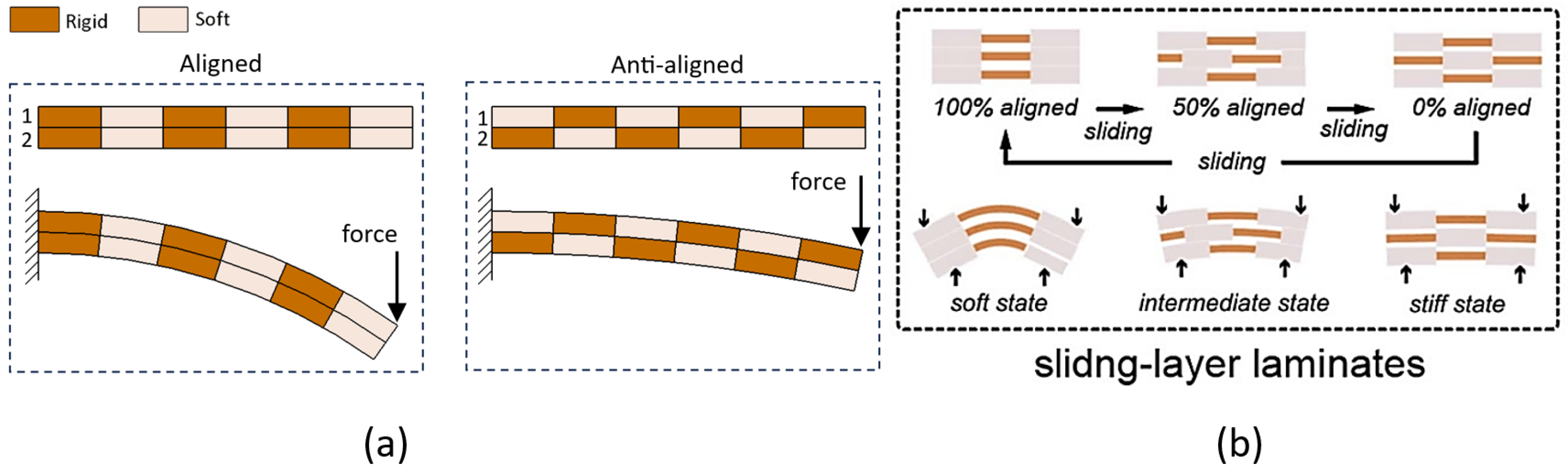
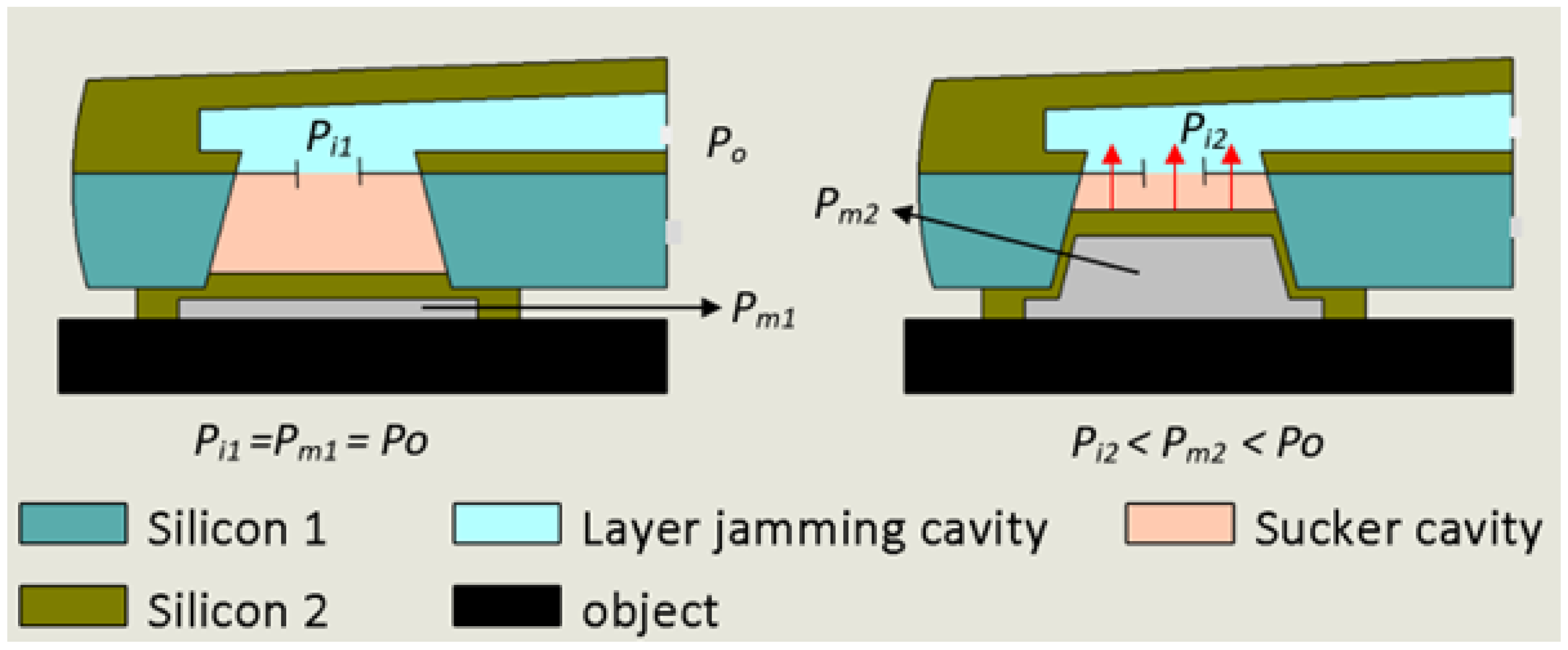
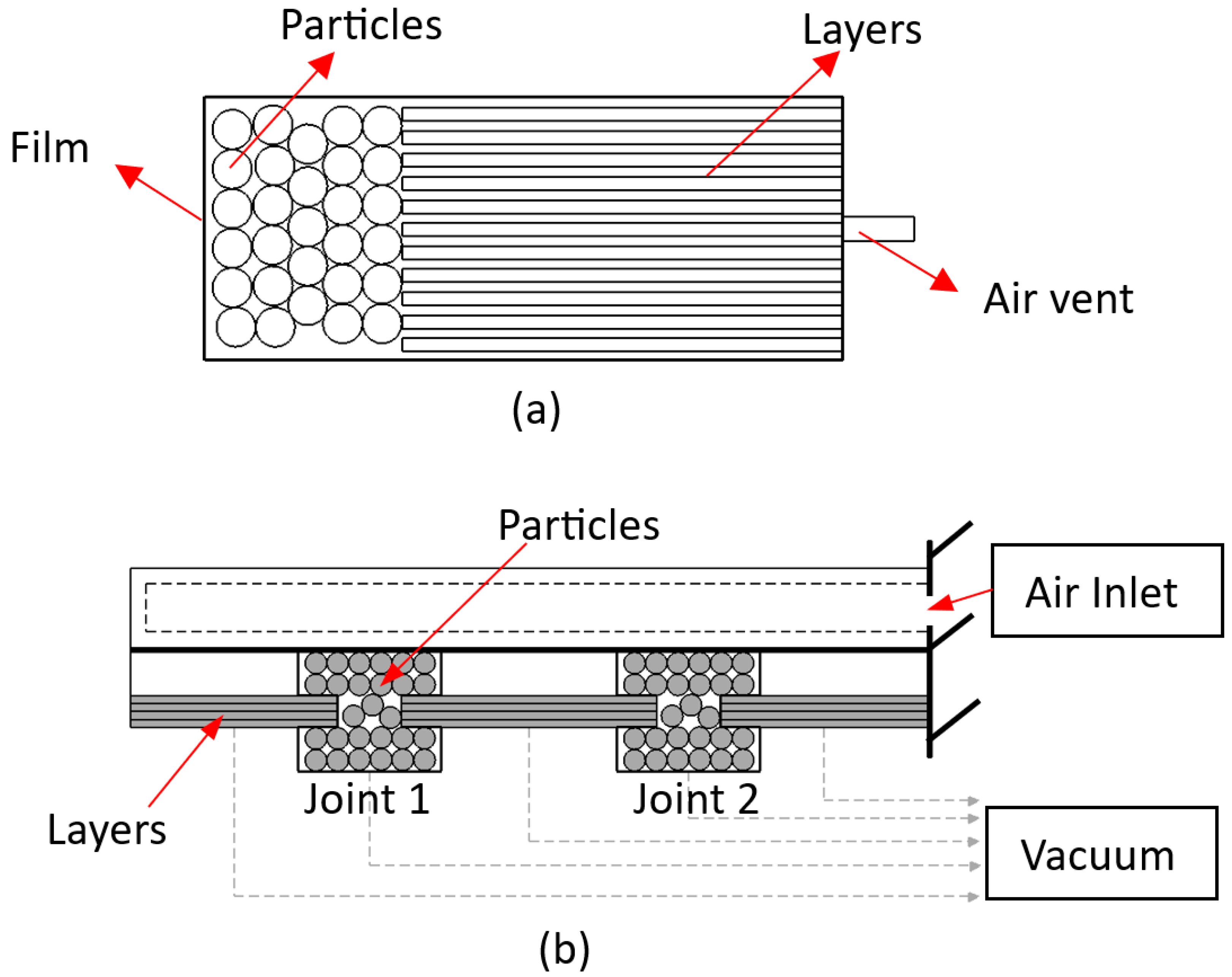
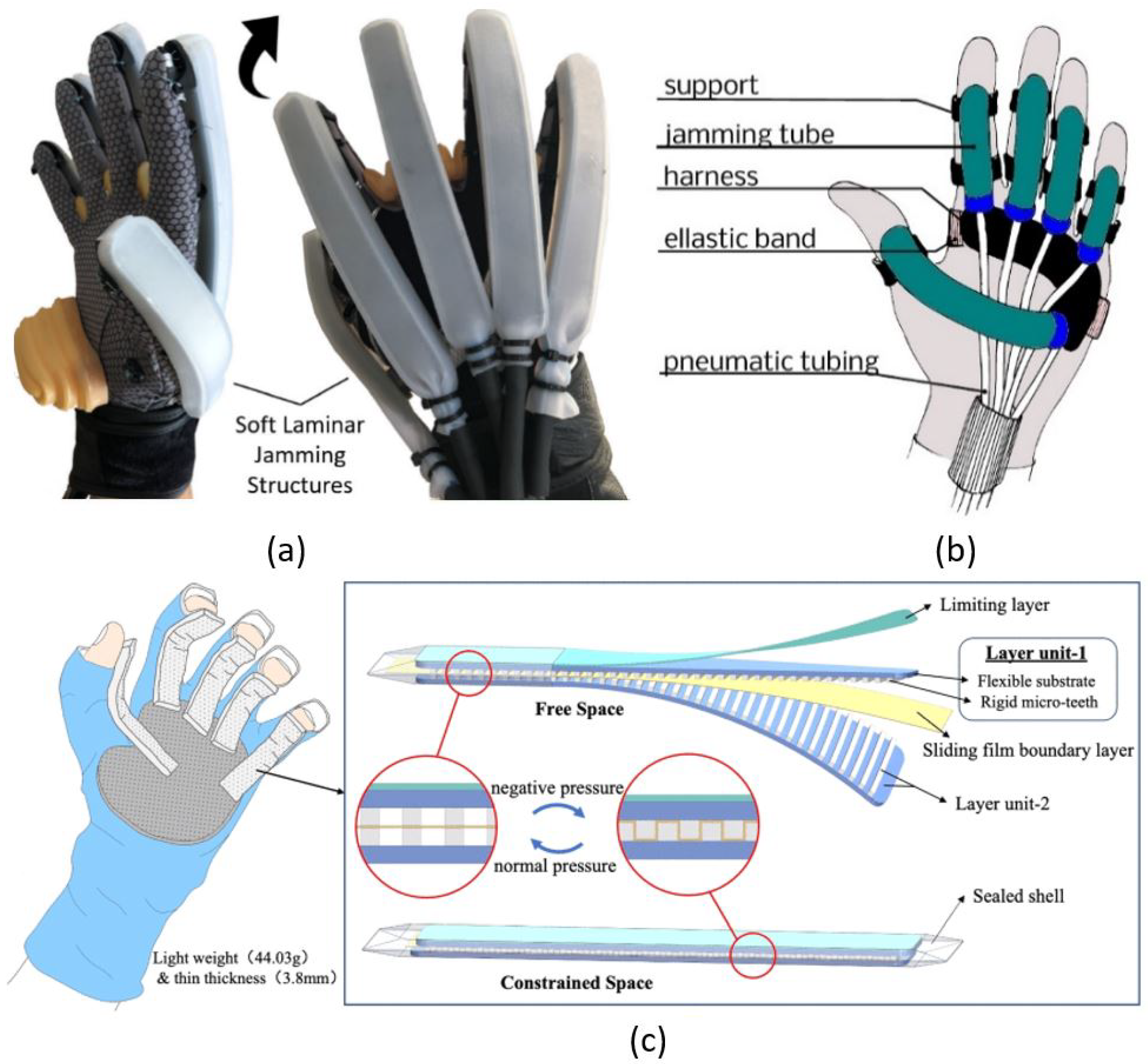
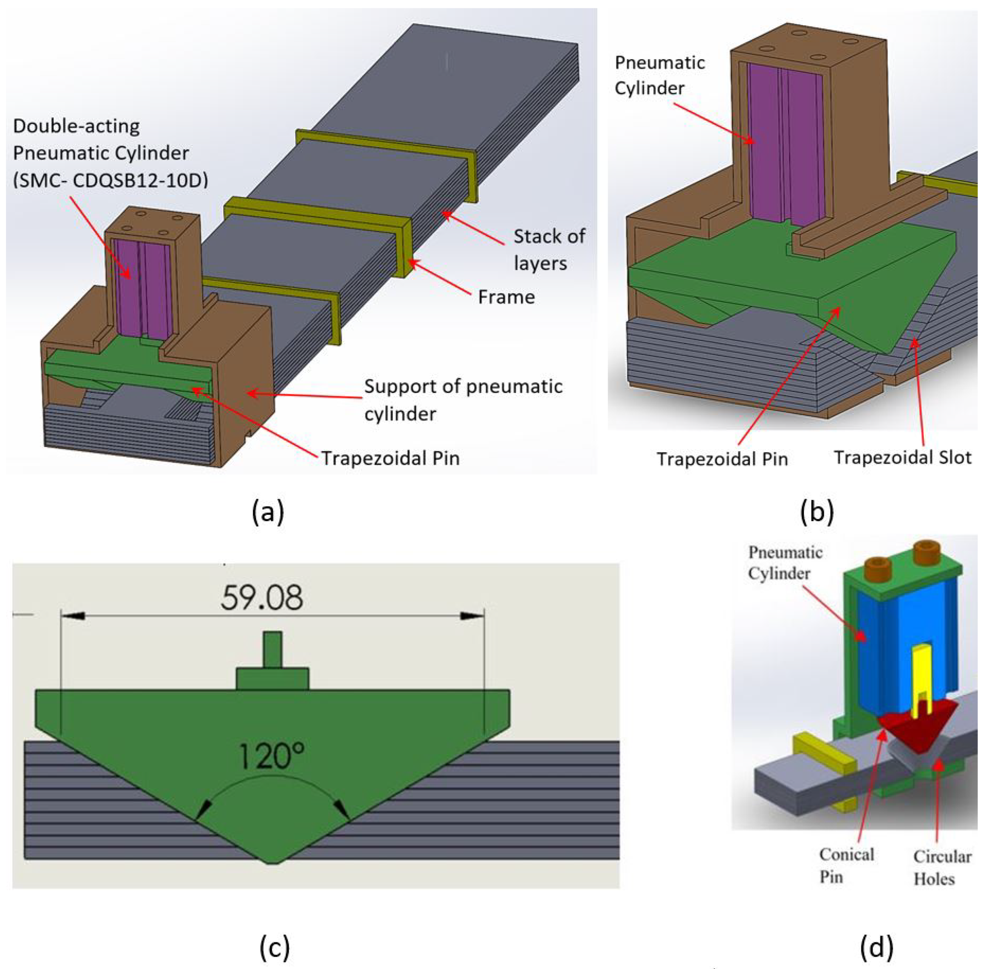
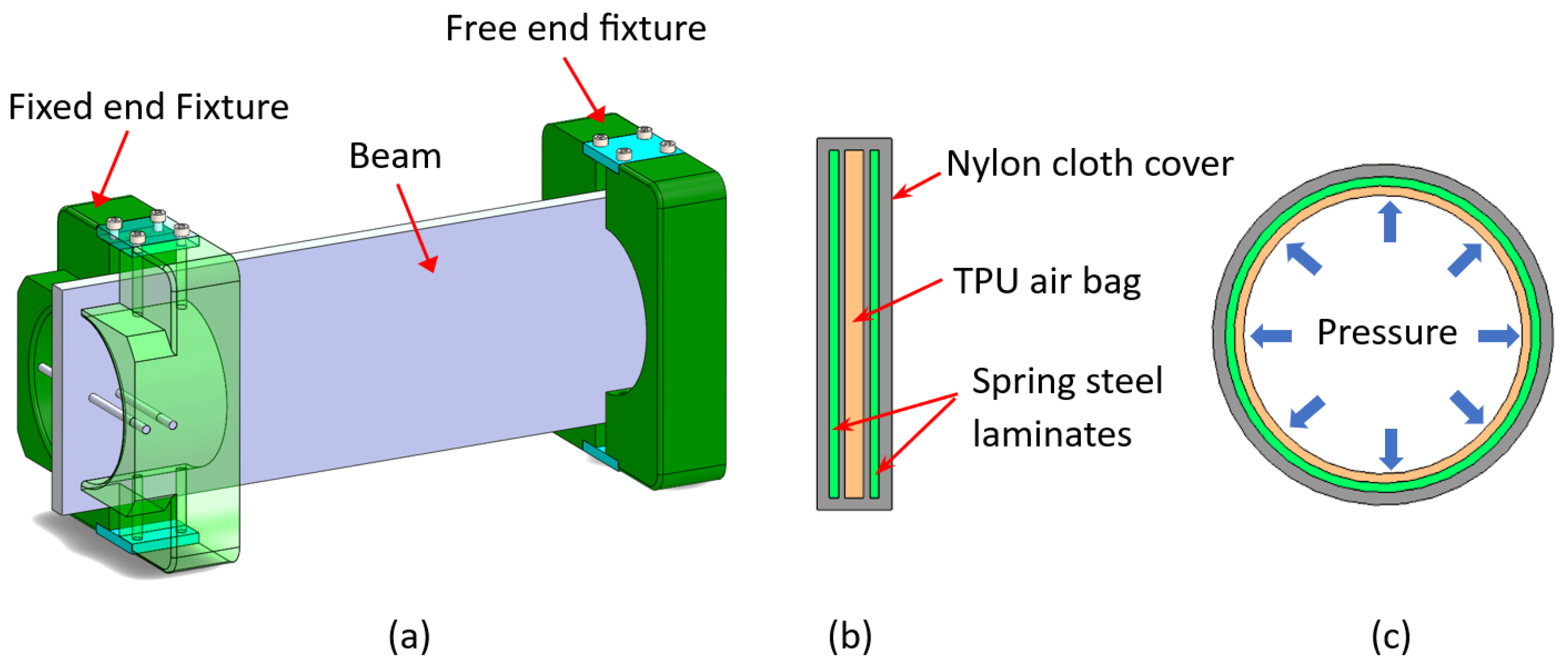
Table 1.
Performance of the fundamental lock/unlock mechanisms of LJ, and some combinations between them (qualitative evaluation scale: ++, +, −, −− from the highest to the lowest values).
Table 1.
Performance of the fundamental lock/unlock mechanisms of LJ, and some combinations between them (qualitative evaluation scale: ++, +, −, −− from the highest to the lowest values).
| Lock/Unlock Mechanism | Speed of Stiffening | Speed of Destiffening | Actuation/Power Source | Stiffness Variation | Example of Stiffness Range (N/mm) | Applications |
|---|---|---|---|---|---|---|
| LJ wrapped by SMA [5] | −− | −− | Electric Power/Thermal Conditions | 60× | 0.03–1.8 | No specific application |
| Electrostatic Force [6,11,12,13,41,52,61,62] | ++ | ++ | Electric Power | 18× | No dataavailable | -robotic fingers -continuum robots -wearable robots -haptic gloves |
| Vacuum Pressure [1,7,14,15,16,17,18,19,20,21,22,23,24,25,26,27,28,29,30,31,32,46,48,53] | + | + | Vacuum Pump | 10–180× | 0.008–1.522 [19] | -grippers and fingers -wearable robots -robot arms -landing gear of UAVs |
| Mechanical Interference [36,37] | − | − | Electric Power/Thermal Conditions | 14.6× | 0.11–1.72 [36] | No specific application |
| LJ with Heating Blankets [38,63] | −− | − | Heat Source/Thermal Conditions | 2.25–4× | 5–18 approx [38] | No specific application |
| Sliding Layer Laminate [39,40] | + | + | Linear Actuator | 3–7× | 0.005–0.035 [40] | Underwater robots |
| Mesh Sheath [9] | No data available | No data available | Mechanical Motion | No data available | Continuum robots | |
| DLJ [8,34,35] | Not applicable | Not applicable | Mechanical/Pressure Clamps | 17× | 0.024–0.4 [8] | Robot arms |
| Trapezoidal Pin [56,57] | + | + | Air Pressure/Pneumatic Cylinder | 3.65× | 0.0276–0.0886 [56] | Robot arms |
| Vacuum Pressure and Mechanical Interference [44] | Not applicable | Not applicable | Vacuum Pump | 26.3× | 0.0474–1.2484 | Haptic gloves |
Disclaimer/Publisher’s Note: The statements, opinions and data contained in all publications are solely those of the individual author(s) and contributor(s) and not of MDPI and/or the editor(s). MDPI and/or the editor(s) disclaim responsibility for any injury to people or property resulting from any ideas, methods, instructions or products referred to in the content. |
© 2024 by the authors. Licensee MDPI, Basel, Switzerland. This article is an open access article distributed under the terms and conditions of the Creative Commons Attribution (CC BY) license (https://creativecommons.org/licenses/by/4.0/).
Share and Cite
MDPI and ACS Style
Caro, F.; Carmichael, M.G. A Review of Mechanisms to Vary the Stiffness of Laminar Jamming Structures and Their Applications in Robotics. Actuators 2024, 13, 64. https://doi.org/10.3390/act13020064
AMA Style
Caro F, Carmichael MG. A Review of Mechanisms to Vary the Stiffness of Laminar Jamming Structures and Their Applications in Robotics. Actuators. 2024; 13(2):64. https://doi.org/10.3390/act13020064
Chicago/Turabian StyleCaro, Freddy, and Marc G. Carmichael. 2024. "A Review of Mechanisms to Vary the Stiffness of Laminar Jamming Structures and Their Applications in Robotics" Actuators 13, no. 2: 64. https://doi.org/10.3390/act13020064
Note that from the first issue of 2016, this journal uses article numbers instead of page numbers. See further details here.