Article

Concept of a Series-Parallel Elastic Actuator for a Powered Transtibial Prosthesis

Robotics & Multibody Mechanics research group, Vrije Universiteit Brussel, Pleinlaan 2, B-1050 Brussels, Belgium
*
Author to whom correspondence should be addressed.
Actuators 2013, 2(3), 59-73; https://doi.org/10.3390/act2030059
Submission received: 21 February 2013 / Revised: 24 June 2013 / Accepted: 25 June 2013 / Published: 3 July 2013
(This article belongs to the Special Issue Human Centered Actuators)

Abstract

:
The majority of the commercial transtibial prostheses are purely passive devices. They store energy in an elastic element during the beginning of a step and release it at the end. A 75 kg human, however, produces on average 26 J of energy during one stride at the ankle joint when walking at normal cadence and stores/releases 9 J of energy, contributing to energy efficient locomotion. According to Winter, a subject produces on average of 250 W peak power at a maximum joint torque of 125 Nm. As a result, powering a prosthesis with traditional servomotors leads to excessive motors and gearboxes at the outer extremities of the legs. Therefore, research prototypes use series elastic actuation (SEA) concepts to reduce the power requirements of the motor. In the paper, it will be shown that SEAs are able to reduce the power of the electric motor, but not the torque. To further decrease the motor size, a novel human-centered actuator concept is developed, which is inspired by the variable recruitment of muscle fibers of a human muscle. We call this concept series-parallel elastic actuation (SPEA), and the actuator consists of multiple parallel springs, each connected to an intermittent mechanism with internal locking and a single motor. As a result, the motor torque requirements can be lowered and the efficiency drastically increased. In the paper, the novel actuation concept is explained, and a comparative study between a stiff motor, an SEA and an SPEA, which all aim at mimicking human ankle behavior, is performed.

1. Introduction

The majority of the commercial transtibial prostheses are purely passive devices. They store energy in an elastic element during the beginning of a step and release it at the end in order to move the body forward. A 75 kg human produces on average 26 J of energy during one stride at the ankle joint when walking at a normal cadence of 105 steps min and stores/releases 9 J of energy, contributing to energy efficient locomotion [1]. According to Winter [1], a subject produces 250 W peak power at a maximum joint torque of 125 Nm. This energy deficit in passive prostheses attributes to greater energy consumption while walking (up to 35% [2]), which leads to early fatigue [3]. Moreover, amputees exhibit an asymmetrical gait pattern, resulting in medical pathologies in the long run [4]. Powering a prosthesis with traditional servomotors leads to too big and heavy motors at the outer extremities of the legs, as is presented in Section 2 of this paper.
Current state-of-the-art research prototypes use series elastic actuators (SEA) [5] to reduce the power requirements of the motor and to mimic the compliance in the lower limb muscle-tendon system [6]. For example, in the SPARKy project (Spring Ankle with Regenerative Kinetics) [7], the linear spring regenerates energy during the stance phase, while the actuator effectively decreases the equilibrium length of the spring after dorsiflexion of the stance phase to supplement the amount of potential energy it stores and releases. With the Robotic Tendon actuator (including a 150 W DC motor) [8], 100% of the push-off power can be provided. A major remaining problem is the high forces/torques that go through the motor and mechanical components, since they are not reduced by the SEA setup (as will be discussed in Section 2 of the paper). Testing indicated service life challenges of, for example, the lead screw assembly in the actuator [9]. To reduce the torques through the motor, Au and Herr placed a spring during the controlled dorsiflexion phase to activate a torque source (SEA with 150 W motor) in parallel when peak power is needed [10]. This prosthetic device has shown its effectiveness by improving, on average, by 14%, compared to evaluated conventional prostheses, the metabolic economy of walking individuals with transtibial amputation [11]. We also demonstrated the importance of the powered push-off by prosthesis with pleated pneumatic artificial muscles (PPAM) [12]. With the AMPfoot 2, the successor of the passive prosthesis AMPfoot 1 [13] with switchable stiffness, the power rating of the motor could even be reduced further by making it work over nearly the complete stride and storing the energy in a locked spring [14]. A second serial spring stores energy during the dorsiflexion phase. During push-off, the energy from both springs are combined to deliver the required energy. Successful walking experiments up to 5 km h (typical speed of a non-amputee) have been demonstrated by a 60 W motor. The second part of this paper studies the SEA and shows that an SEA is indeed able to reduce the power requirements of the motor, but the torque, which needs to be generated by the motor, remains equal.
As shown in [15], the mass of the motor, M, is linearly related to the maximum torque it can deliver: T max 55 M 0.999 . Moreover, for electromagnetic motors, the torque relates to the L by M L 5 (assuming constant efficiency) or M L 3.5 (assuming similar motor temperatures) with L being the characteristic length of reference [16]. As a result, large robots require large motors and gearboxes, which is often hardly possible. One solution is to implement a spring in parallel to reduce the motor torque. The first possibility is to implement a spring in parallel to a stiff actuator, often referred to as PEA [17,18]. The downside here is that the overall output is still a stiff actuator. A second approach is to place a spring in parallel to an SEA, as done by Hugh Herr in the powered ankle-foot prosthesis [10]. The disadvantage of passive springs in parallel to an actuator is that they limit movement dexterity [18]. As the parallel spring is always engaged, these actuators tend to recoil the stored energy and induce joint motions that counter desired ones. To resolve this problem, [19] designed the clutchable parallel elastic actuator concept (CPEA) to provide load cancellation when the clutch is on. When the clutch is off, however, the motor still needs to deliver the full required output torque.
To cope with the problem of the high torques through the motor and gearbox, a novel human-centered actuator concept is developed, which is inspired by the variable recruitment of muscle fibers in a human muscle. A muscle can be progressively activated by successive motor unit recruitment [20]. We call this concept series-parallel elastic actuation (SPEA), and it consists of multiple parallel springs, each connected to an intermittent mechanism with internal locking, which are mutually dephased and driven by a single motor [21,22]. The SPEA enables variable recruitment of parallel springs, due to the dephased intermittent mechanisms, and adaptive load cancellation, due to the internal locking of each intermittent mechanism. A proof of concept consisting of four parallel springs has been shown to lift an object and perform a cyclic motion; the motion can be performed with a motor torque, which is about 1 4 of the output torque, with 11% of the electrical energy compared to a stiff setup [21,22]. In this paper, we will study the potential of the SPEA on the motor requirements of a transtibial prosthesis and compare these results with those of the stiff set-up and the SEA. More information concerning the underlying working principle of the SPEA can be found in Section 4.1. We hope that this novel actuation concept is the start of new research towards more efficient actuators, which are needed for the next wave of technology [23].
Section 2 discusses the reference trajectories that are used for a powered transtibial ankle prosthesis driven by a stiff actuator. In Section 3, the performance of an SEA in the same application is studied. Section 4 starts with an elaboration on the underlying principles of the SPEA. After derivation of an SPEA model, which is equivalent to the SEA model, which will be derived in Section 3, the potential of an SPEA for driving a powered transtibial ankle prosthesis is studied. In Section 5, the results are compared, and the potential of the SPEA is further discussed. The conclusions are drawn in Section 6.

2. Stiff Set-Up or Servomotor

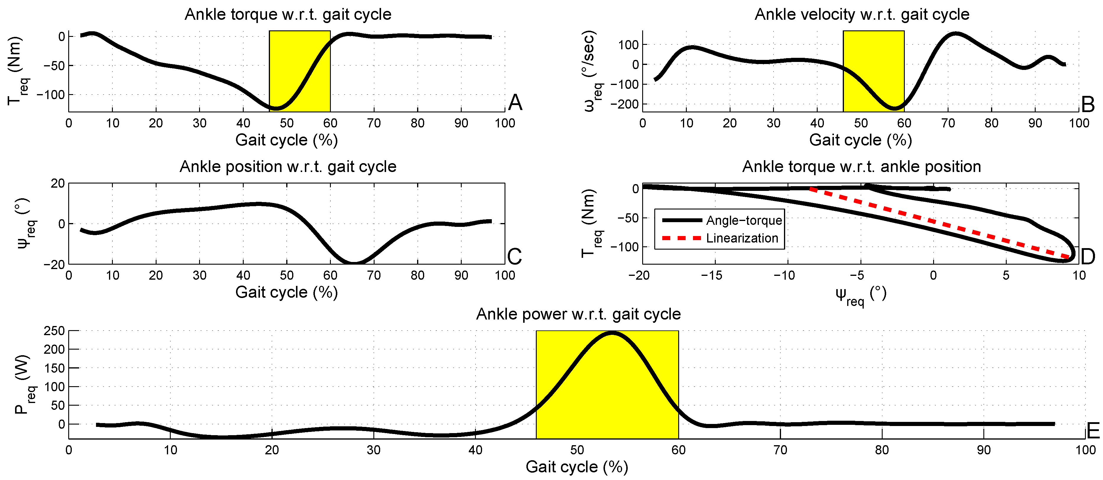
2.1. Reference Data of Winter

The biomechanics of human gait are studied in [1]. This work provides gait data of the human ankle, presented in Figure 1, for a 75 kg person as a function of the percentage of gait cycle. The cadence is 105 steps min . This is indicated by the shaded yellow areas in the torque, velocity and power profiles; the human ankle has to deliver a high peak halfway during the gait cycle in order to generate the push-off that moves the body forward. The solid curve in Figure 1(D) indicates the torque-angle characteristic of the human ankle profile and the dashed line the average linear fit; both will be further discussed in Section 3. In this paper, Winter’s data will be used as the required output profile for a stiff actuator, an SEA and an SPEA that all aim at mimicking human ankle behavior.
Figure 1. Torque, velocity, position, angle-torque and power graphs (respectively (A–E)) as a function of the gait cycle for an ankle of a 75 kg person, taken from Winter [1]. The yellow shaded areas correspond to the part of the gait cycle with the peak power during push-off. The dashed line in (D) is the linear fit of the solid torque-angle graph.
Actuators 02 00059 g001

2.2. Motor Selection in Stiff Set-Up
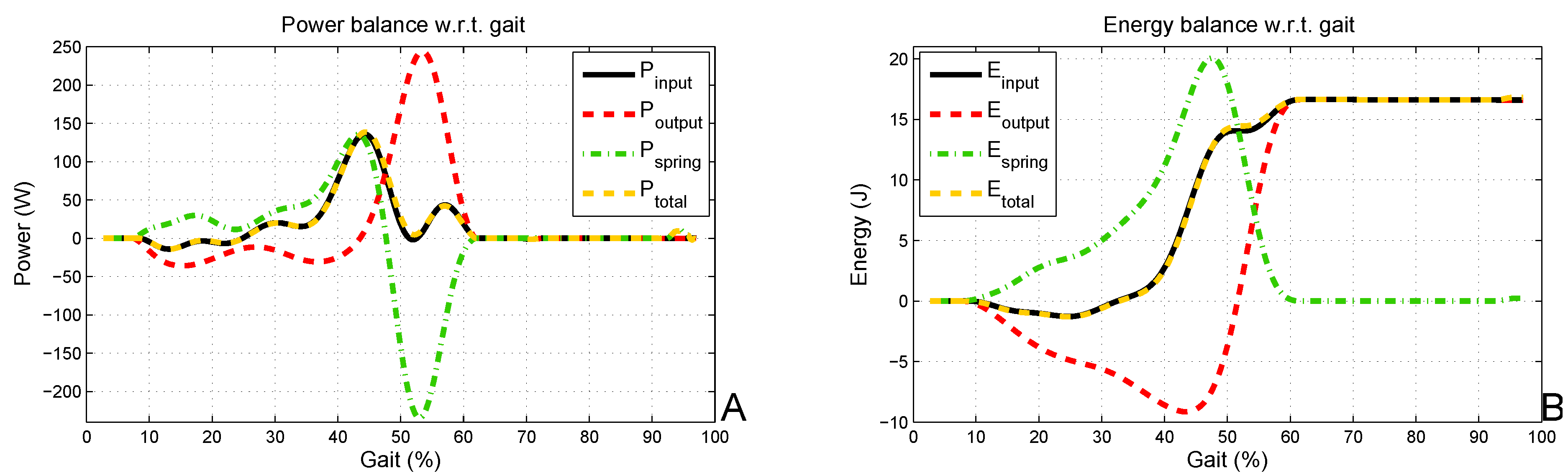
To mimic human ankle behavior with a stiff set-up, a DC motor and gearbox should be found that can deliver 250 W, 125 Nm and 4.5 rad s or 43 rpm.
This is a challenge, since the set-up should be light and compact, as well, in order to fit the ankle joint. To indicate this problem, a search in the Maxon Motor catalog is performed. The EC-4pole 45 motor is rated for 300 W, delivers a nominal torque of 0.635 Nm at 3,580 rpm and weighs 1.130 kg. Combined with a planetary gearhead GP 42C with a gearing ratio of 24:1, this is reduced to approximately 15 Nm at 150 rpm nominal and an additional weight of approximately 0.400 kg. An extra custom-made gearbox with a ratio of 4:1 in series then delivers 60 Nm at 37.5 rpm. This custom gearbox will be heavy, as it has to withstand 60 Nm. Furthermore, increasing the torque with gearboxes will decrease the motor speed, and the required 43 rpm cannot be reached anymore. The only solution is a combination of two EC-4pole 45 with planetary gearheads GP 42C and custom made gearboxes with a 4:1 ratio. The weight then increases over 3 kg plus twice the weight of the custom-made gearbox, which is unacceptable. Since a DC motor cannot store and release energy, the total energy requirement for one stride is equal to 35 J, which is the integral of the absolute value of Winter’s power curve.

3. SEA Set-Up

This section will discuss the features and drawbacks of an SEA for mimicking human ankle behavior by means of calculations for a general drum-drum SEA setup followed by an optimization of the spring constant, k SEA , and a motor selection according to the results of this optimization.

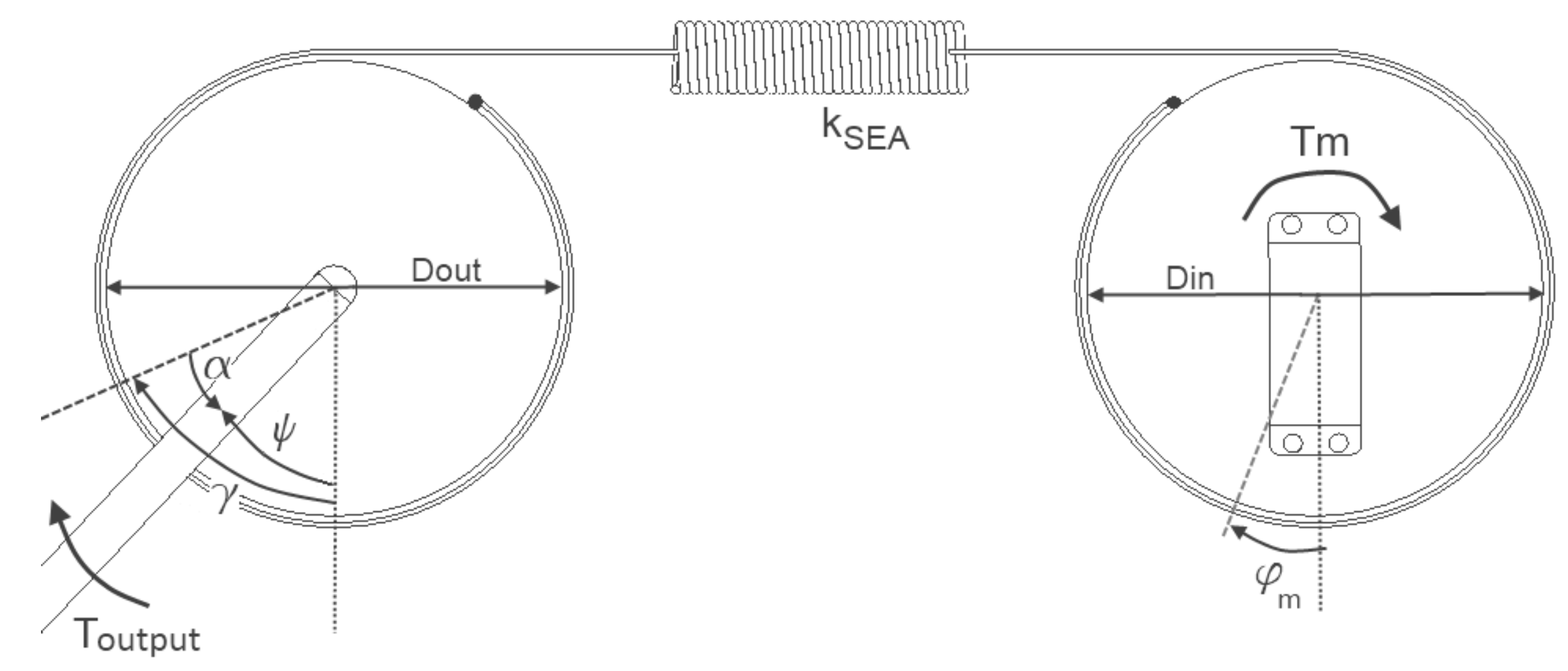
3.1. SEA Agonistic Drum-Drum Set-Up

Winter’s data shows that the ankle torque in Figure 1(A) is mostly negative, with a negative peak of −125 Nm and a positive peak of 5.5 Nm. For this paper, we will modify the ankle torque profile, so that all the positive torques are set to 0 Nm and an agonistic (or uni-directional) set-up is sufficient. In practice, a relatively small parallel return spring can constantly deliver 5.5 Nm, so that the torque curve is shifted vertically and only negative torques are required. Figure 2 presents the agonistic SEA drum-drum set-up and all the relevant parameters. The drum-drum set-up allows one to reduce the complexity of the equations to calculate the motor profile ( T m , ω m and φ m ) as a function of a certain required output profile ( T req , ω req and ψ req ). The following equations describe the set-up of Figure 2. At equilibrium position, the deviation angle, α, is equal to 0 rad when the torque, T output , applied by the SEA is equal to 0 Nm. The output torque of the SEA is directly related to the deviation angle, α. The relation between α and T output is:
α = T output k SEA 4 D out 2
The equilibrium angle of the output drum, γ, can now be found by the following relation:
γ = ψ output α
The relation between the equilibrium angle on the output side, γ, and on the input side, φ m , is: φ m = D out D in γ . The relation between T output and T m is similar, since the motor is in series with the output via the spring:
T m = T output D in D out
By means of the above equations, it is possible to express the motor angular velocity, ω m , and the motor torque, T m , as a function of a certain required output profile ( T req , ω req and ψ req ). The same is possible for the motor power, P m , since it is equal to the product of the motor angular velocity, ω m (the derivative d φ m d t ), and the motor torque, T m . By means of Equation (2) and Equation (3) and the derivative of Equation (1), one can find an expression for P m as a function of a certain required output profile ( T req , ω req and ψ req ):
P m = T req ω req + d T req d t 4 k SEA D out 2
The fraction in Equation (4) accounts for the power in the spring. This model is then used to optimize the spring constant, k SEA , for minimizing the motor peak power (PP) and the energy requirements (ER) of the motor. The results are shown in Figure 3. The PP can be lowered by lowering the motor speed, and the ER can be lowered by storing and recovering part of the negative energy in the spring. An SEA enables one to modify P m by modifying ω m . T m , however, cannot be changed, since the motor is always in series with the spring. This is clearly visualized in Figure 3(A,B).
Figure 2. All the relevant parameters of the SEA agonistic drum-drum set-up indicated on a scheme. On both the input drum (right) and the output drum (left), a wire is fixed, which are each connected to one of both sides of an extension spring.
Actuators 02 00059 g002
Figure 3. The motor requirements for both stiffnesses are plotted in (A,B,C). As indicated by (D,E), the optimization for energy requirements (ER) and peak power (PP) results in a different stiffness.
Actuators 02 00059 g003
Figure 3(D,E) clearly show that PP and ER can be lowered for an SEA set-up in comparison with a stiff set-up by selecting an appropriate stiffness, k SEA . For D i n = D out = 0.10 m, the minimum PP is 95 W for k SEA = 239,000 N m , and the minimum ER is 19.5 J for k SEA = 155,000 N m . For k SEA N m , the SEA set-up becomes a stiff setup, and PP and ER asymptotically approximate the stiff values: PP = 250 W and ER = 35 J. This can be understood, since for k SEA N m , it is clear that α 0 r a d in Equation (1) and, thus, φ m ψ req . For k SEA 0 N m , both PP and ER reach infinity, since motor speeds are reaching infinity. This can be understood, since for k SEA 0 N m , it is clear that if α r a d in Equation (1) and, thus, φ m r a d .
It is interesting to note that the optimal stiffness, k SEA , for minimum ER can be found by a short back-of-the-envelope calculation. The solid curve in Figure 1(D) is the angle-torque relation of the SEA and actually represents the torsional stiffness, K SEA , in Nm rad . Since Δ E x t e n s i o n = Δ A n g l e D out 2 , the relation between the linear stiffness, k SEA , and the torsional stiffness, K SEA , is:
K SEA = k SEA D out 2 4
The motor in an SEA should minimally deliver the inner surface of the angle-torque curve. A stiff set-up, however, needs to deliver the surface between the x-axis and the minimum of the angle-torque curve. By deploying a spring with linear stiffness, k SEA , that relates to the torsional stiffness, K SEA , of the dashed average line in Figure 1(D), the ER can be minimized. Since the dashed red line connects the points, (−8.5 ,0 Nm) and (9.6 ,−120 Nm), the slope results in the torsional stiffness, K SEA :
K SEA = a b s ( 0 Nm 120 Nm 9 . 6 ( 8 . 5 π rad 180 ) ) = 379 Nm rad
By means of Equation (5), the linear stiffness, k SEA = 151,940 N m , is found. This is indeed close to the optimal k SEA for the minimum ER, k SEA = 155,000 N m , found above. The energy and power curves in Figure 4 confirm the above described principles of the SEA. More information on finding the optimal stiffness for a given trajectory is provided in [24]. By means of two working principles, the SEA aims to avoid delivering a high power peak for a short period in a stiff set-up. Firstly, part of the kinetic energy that the motor should dissipate by braking in a stiff set-up can be stored in the spring. This is indicated by P spring in green in Figure 4, which is higher than P input in black in Figure 4 at about 15% of the gait cycle. Secondly, PP for an SEA is lower than for a stiff set-up, but P input for an SEA is more smeared, as shown in Figure 4. As a result, at the peak of P output , P input is relatively small, but P spring is high, so that the spring delivers most of the power. This principle is also used, for example, to increase the jumping height of a jumping robot [25] or to increase the throwing distance of a ball [26] by deploying compliant actuators.
Figure 4. The power balance in (A) shows that P total equals P input , with P total = P spring + P output . The same goes for the energy balance in (B). Both balances are for a stiffness of k SEA = 155,000 N m .
Actuators 02 00059 g004

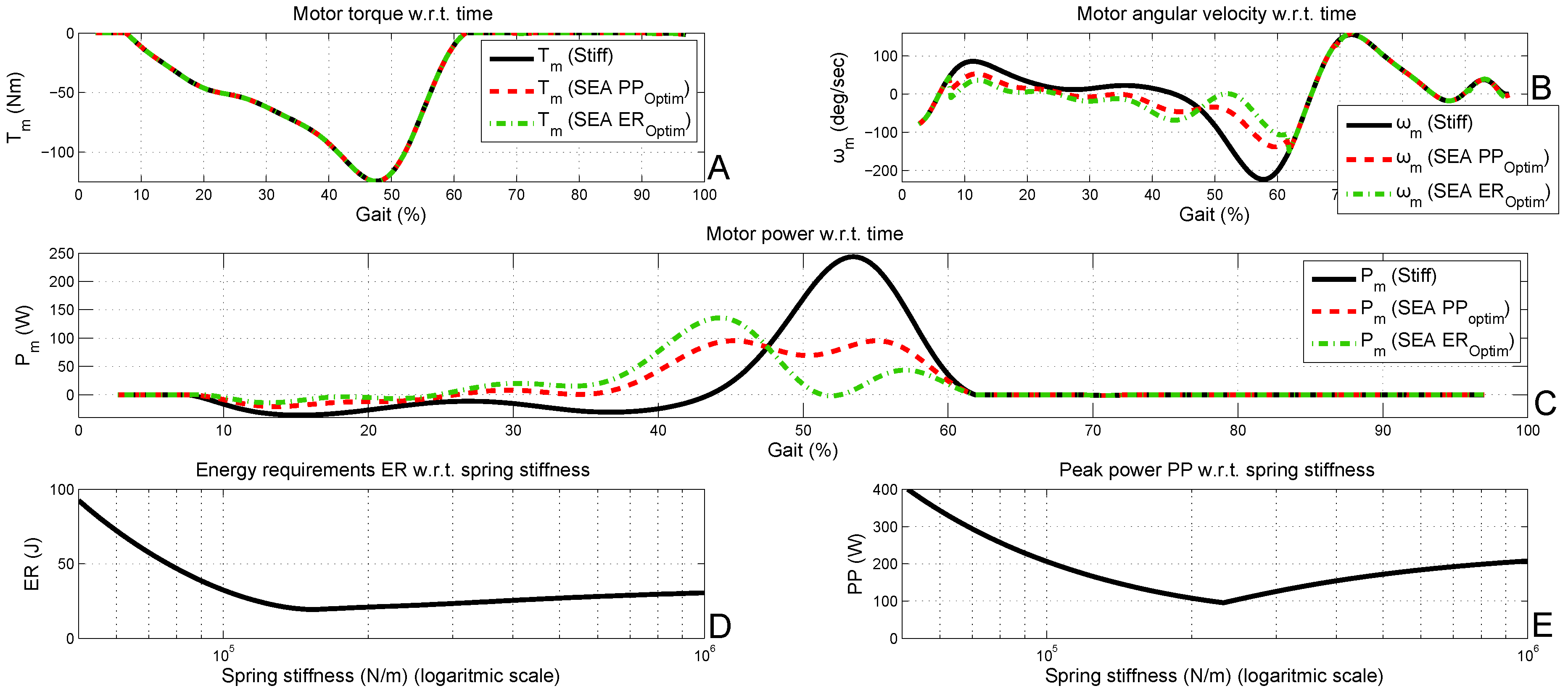
3.2. Motor Selection in SEA Setup
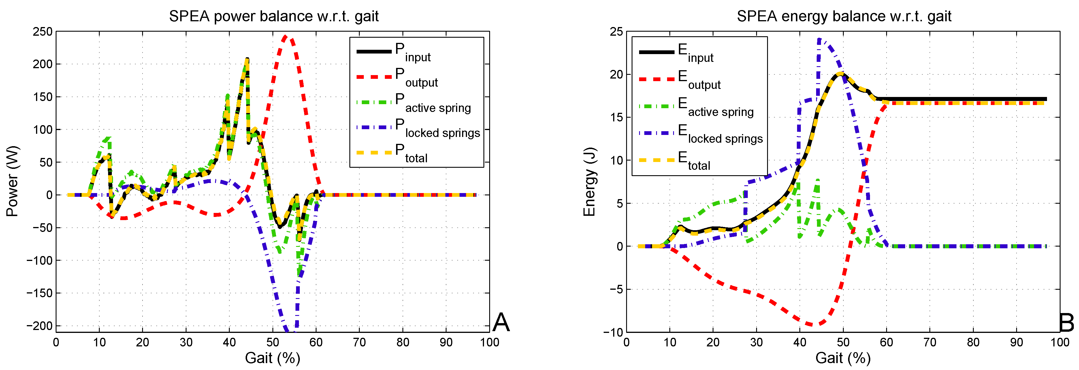
As can be seen from Figure 3, to mimic the human ankle behavior with an SEA, a DC motor and gearbox should be found that can deliver 95 W, 125 Nm and 2.4 rad s or 23 rpm. These requirements are indeed lower than for a stiff set-up: 250 W, 125 Nm and 4.5 rad s or 43 rpm.
The EC-4pole 30 motor, rated for 100 W, delivers a nominal torque of 0.0644 Nm at 16,700 rpm and weighs 0.210 kg. Combined with a planetary gearhead GP 42C with gearing ratio of 235:1, this is reduced to approximately 15 Nm at 71 rpm nominal and an additional weight of approximately 0.560 kg. An extra custom made gearbox with a ratio of 4:1 in series then delivers 60 Nm at 17.8 rpm. This custom gearbox will be heavy, as it has to withstand 60 Nm. Since the SEA is not able to lower T m , the SEA still needs to deliver 125 Nm. Further increasing the torque with gearboxes will decrease the motor speed, and the required 23 rpm cannot be reached anymore. The only solution is a combination of two EC-4pole 30s with planetary gearheads GP 42C and custom-made gearboxes with a 4:1 ratio. The total weight of the two motors and planetary gearheads is then over 1.5 kg, plus the custom made gearboxes, the spring and the drums. This is better than the stiff set-up, but still very high for a one DOFankle. The SPEA concept discussed in the following section aims to offer a solution for this problem.

4. SPEA Set-Up

This section discusses the novel SPEA concept and the possibilities this concept offers for mimicking human ankle behavior.

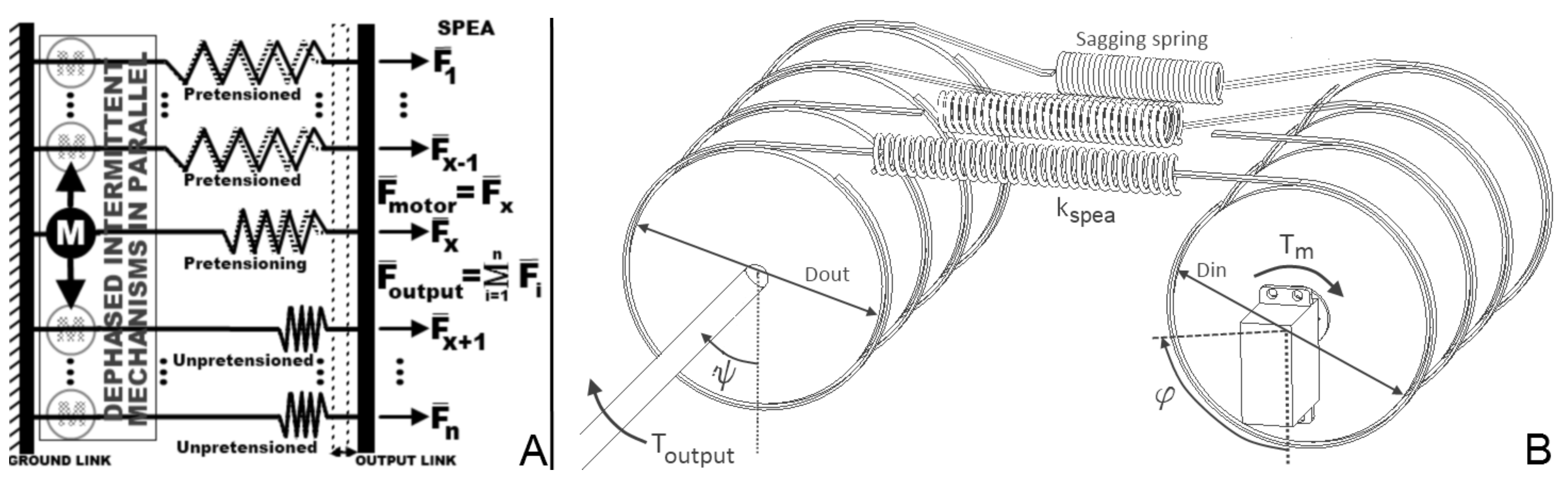
4.1. SPEA Agonistic Drum-Drum Set-Up

The above discussed stiff and SEA set-ups have one major drawback in common: the required torque profile, with a maximum of 125 Nm, has to be delivered in both configurations by the motor and the gearbox. As a result, two heavy gear trains and two heavy motors [15] are required, which makes the set-ups inappropriate to fit a human ankle. As introduced in Section 1, an SPEA consists of a bundle of parallel springs, for which every spring can be contracted and locked over the joint, one after the other, by an intermittent mechanism [21,22]. As depicted in Figure 5(A), each parallel spring of the SPEA can be in one of the following three phases:
  • The unpretensioned phase: the intermittent mechanism is locked, the spring is at its rest length and fixed to the ground link and the output link; all forces that are exerted will not pass through the motor, since it is not present in the force path (shaded motor);
  • The pretensioned phase: the intermittent mechanism is locked, the spring is fully extended and fixed to the ground link and the output link; all forces that are exerted will not pass through the motor, since it is not present in the force path (shaded motor);
  • The pretensioning phase: the intermittent mechanism is unlocked, the motor controls the length of the spring and brings it from the unpretensioned phase to the pretensioned phase or vice versa (solid black motor).
Since each spring can be locked in its pretensioned position, the motor will only feel a fraction of the total output torque. Figure 5(A) shows a scheme of an SPEA with n dephased intermittent mechanisms and springs in parallel. The motor (circle in solid black) can successively switch position (circles in dashed gray) by means of the intermittent mechanisms. When the motor is turned over φ s w i t c h , the spring in the pretensioning phase will go to the unpretensioned or pretensioned phase, and the next spring will enter the pretensioning phase. A scheme of the agonistic drum-drum SPEA, which will be modeled hereafter, is shown in Figure 5(B). The dephased intermittent mechanisms can be developed based on different mechanical principles [27], which are out of the scope of this paper. In [21,22], for example, we used so-called mutilated gears with a locking ring as an intermittent mechanism.
Figure 5. A general scheme of an series-parallel elastic actuation (SPEA) with dephased intermittent mechanisms in parallel in (A) and a scheme of the agonistic drum-drum SPEA with all the relevant parameters in (B). The agonistic drum-drum SPEA is based on the SEA set-up in Figure 2.
Actuators 02 00059 g005
When all the springs are in the unpretensioned phase (and thus, all the input drums at the equilibrium position), a positive ψ output will extend all the parallel springs and, as such, generate a negative T output . In contrast, for a positive ψ output , all the springs will sag and the T output is 0 Nm.
The motor angle, φ m , is 0 rad at the reference position and can be positive or negative. At multiples of φ s w i t c h , the SPEA switches to the next parallel spring. When φ m starts at 0 rad and decreases, the SPEA will tension the first spring until φ m = φ s w i t c h and, then, continue to tension the next springs and make the T output more negative. Since the setup is agonistic, T output can, of course, only be negative. The above reasoning makes us conclude that T output is determined by ψ output and φ m and equals:
T output = k SPEA i = 1 n E x t e n s i o n i D out 2
i = 1 n E x t e n s i o n i consists of three terms: one corresponds to the extension of the pretensioned spring(s), the second corresponds to the extension of the pretensioning spring and the third corresponds to the unpretensioned spring(s). i = 1 n E x t e n s i o n i can be determined by Equation (8). S p ( x ) = x a b s ( x ) 2 returns x when x is negative and returns zero when x is positive, to describe the effect of sagging springs. The number of pretensioned springs is equal to p 1 . Spring p is in the pretensioning phase. Sign(x) returns a zero when x is zero, a one when x is positive and negative one when x is negative. The total extension of the unpretensioned springs (from spring 1 to p–1), the pretensioning spring (spring p) and the pretensioned springs (from spring p + 1 to n) can be calculated, respectively, as follows:
i = 1 p 1 E x t e n s i o n i = S p φ s w i t c h D i n 2 ψ output D out 2 ( p 1 )
E x t e n s i o n p = S p φ m D i n 2 ( p 1 ) φ s w i t c h D i n 2 ψ output D out 2
i = p + 1 n E x t e n s i o n i = S p ( n p ) ψ output D out 2
Because of the intermittent character of the SPEA, the equations to calculate the motor profile ( T m , ω m and φ m ) as a function of a certain required output profile ( T req , ω req and ψ req ) are not analytical anymore. Instead, φ m can be found by iteration of Equation (7) until T output = T req . The torque produced by the motor, T m , the sum of torques generated by the locked springs, T locked (i.e., the unpretensioned springs and the pretensioned springs), and the torque produced by the active spring, T active (i.e., the pretensioning spring), are calculated as follows:
T m = E x t e n s i o n p k SPEA D i n 2
T l o c k e d = i = 1 p 1 E x t e n s i o n i + i = p + 1 n E x t e n s i o n i k SPEA D out 2
T a c t i v e = T m D out D in
By means of Equations (7–9), one can find T m and φ m and, thus, also, ω m by derivation and P m = T m ω m . In Figure 6, the calculated motor data of an SPEA with four springs that mimics the human ankle behavior is presented. To mimic the human ankle behavior with an SPEA with four springs, a DC motor and gearbox should be found that can deliver 208 W, 32 Nm and 6.4 rad s or 61 rpm. The motor needs an energy input of 24.6 J each stride. The stiffness, k SPEA , is the stiffness of one of the parallel springs, and k is chosen, so that T m is sufficiently lowered and ER and PP are still acceptable (24.6 J and 208 W). For the results presented in this section, k equals 118,100 N m . T m is clearly lowered by approximately 1 n of T req (with n = 4). In contrast, φ m increases. This is good, since this avoids the need for big reductions, since a DC motor typically has a high nominal speed and a low nominal torque. Around 50% of the gait cycle, T req , reaches its maximum; thus, three springs are pretensioned, and the last spring is in the pretensioning phase. Furthermore, at this point, the locked springs deliver most of the power for push-off, as indicated in Figure 7.
Figure 6. The SPEA simulation results. Figure (A) clearly illustrates that the motor torque at the input side, T input , is lower compared to the required output torque, T req . The number of pretensioned springs p-1 rises to 3 as indicated in (C). As a result, the maximum motor position, φ m , and speed, ω m , are increased compared to the output angle, ψ req , and speed, ω req , in (D) and (B).
Actuators 02 00059 g006
Figure 7. The power and energy equilibrium of the SPEA are shown in (A) and (B). The motor peak power, P input , has a short peak at 200 W and one at 150 W. Besides both peaks, the motor power is always lower than 100 W.
Actuators 02 00059 g007

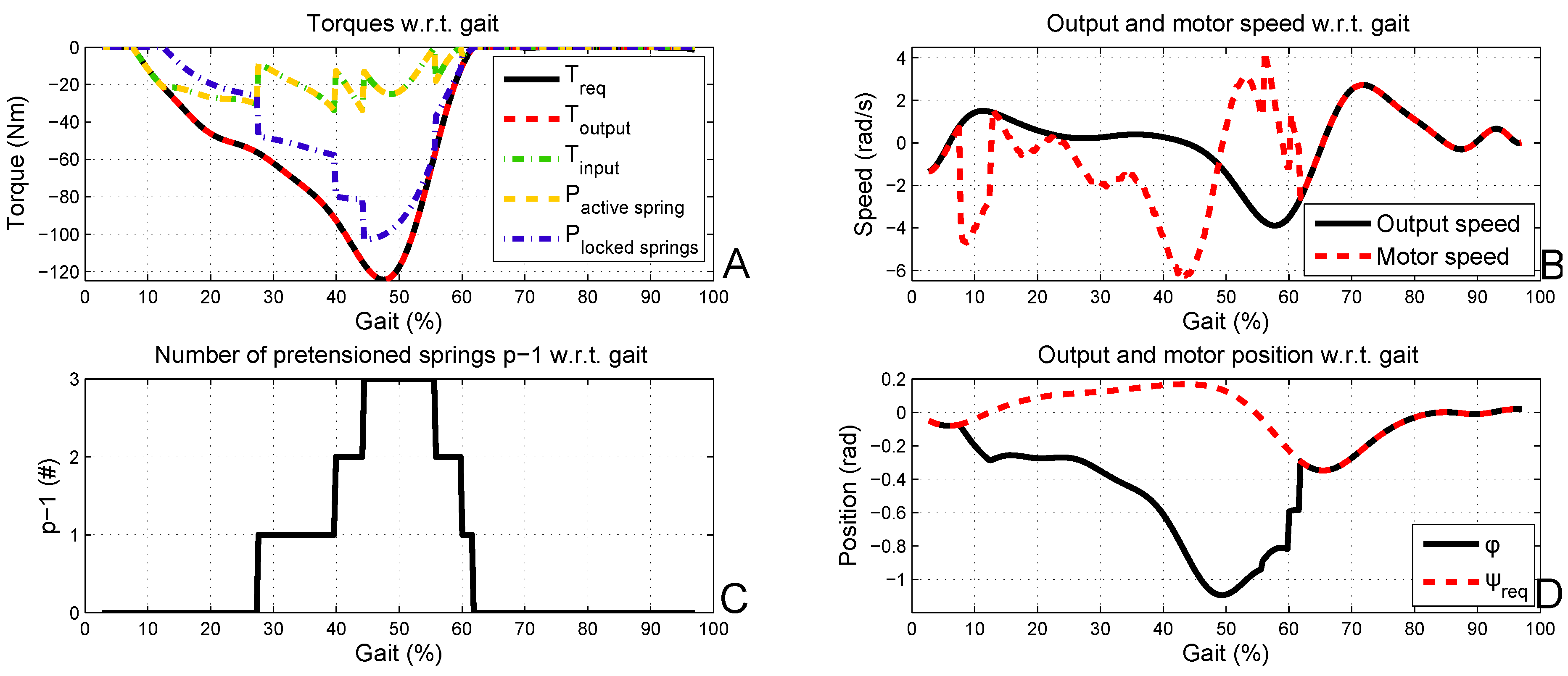
4.2. Motor Selection in SPEA Setup

As can be seen in Figure 6 and Figure 7, to mimic the human ankle behavior with an SPEA, a DC motor and gearbox should be found that can deliver 208 W, 32 Nm and 6.4 rad s or 61 rpm.
The EC-4pole 30 motor rated for 200 W delivers a nominal torque of 0.112 Nm at 16,200 rpm and weighs 0.300 kg. Combined with a planetary gearhead GP 42C with a gearing ratio of 142:1, this is reduced to approximately 15 Nm at 114 rpm nominal and an additional weight of approximately 0.460 kg. This solution requires only one motor and planetary gearhead, with a total weight of approximately 0.760 kg. An extra custom-made gearbox with a gearing ratio of 2:1 in series then delivers 30 Nm at 57 rpm, plus the weight of the four springs with stiffness, k SPEA , the drums and the intermittent mechanism. Because of the lowered motor torques, the weight of the motor can be lowered, as well as the weight of the gearheads.

5. Discussion

In this section, we will summarize the results regarding the motor selection for mimicking human ankle behavior with a stiff set-up, an SEA and the novel SPEA, in Table 1.
The question remains whether it is beneficial to implement an SEA with multiple dephased intermittent mechanisms and springs in parallel instead of a stiff set-up or SEA, especially regarding weight and complexity. It is clear that a stiff set-up can only deliver the required ankle profile with a combination of two excessively heavy motors and gearboxes in parallel. Both the peak power of 250 W and the peak torque of 125 Nm are challenging. The simulations for the SEA clearly show that the SEA enables one to lower the motor speeds and, as such, lower the power requirements of the motor to 95 W. As a result, the mass of the motor can be lowered. Haddadin et al. showed in [28] that the reduction in motor size for an SEA can indeed compensate for the extra required mechanism and spring in comparison to a stiff set-up. However, as shown in this paper, both set-ups require excessive motors and gearboxes when high output torques/forces are required. The torque peak of 125 Nm remains, and a combination of two motors, for the SEA, with excessive gearboxes is still required to mimic human ankle behavior. The novel SPEA concept enables one to lower the motor torque as a function of the number of springs in parallel. Like this, only one motor is required, and the gearing ratio and mass of the gearboxes can be reduced. This is indicated by the ‘total weight’ column in Table 1. On top of this ‘total weight’, the stiff set-up and the SEA require two custom-made gearboxes with a gearing ratio of 4:1 and a maximum torque of 60 Nm. The SPEA only requires one custom-made gearbox with a gearing ratio 2:1 and a maximum torque of only 30 Nm. Compared to the SEA, the SPEA requires n − 1 more parallel mechanisms and springs. These mechanisms can, however, be downscaled, since the forces/torques each parallel mechanism should endure are approximately n-times lower compared to the SEA mechanism. Furthermore, the springs in the SPEA will be lighter than the one in the SEA, since the stiffness is lower. Another important advantage, which is so far undiscussed, is the decrease in losses in the SPEA. Since the torques/forces in the gearbox are reduced, the losses will decrease, as well. This saves energy and, thus, battery weight. The complexity increases for the SPEA. We believe this is detrimental though feasible, since current production techniques, such as multi-material printers, are developing rapidly. In conclusion, it is clear that the design of an optimal SPEA for a specific application will be the result of an optimization. Developing a method for this optimization is part of our future work.
Table 1. Summary of the results for the stiff set-up, SEA and SPEA. It is clear that the stiff set-up and SEA will be heavier than the SPEA.
ReqMaxon MotorMaxon Gear#Total+Custom Gear+Extra
Stiff250 WEC-4pole 45GP42C 24:124:1
125 Nm300 W & 1.13 kg0.40 kg 3.0kg
43 rpmNom: 0.635 Nm15 Nm 60 Nm
Nom: 3580 rpm150 rpm 37.5 rpm
SEA95 WEC-4pole 30GP 42C 235:124:11 spring
125 Nm100 W & 0.21 kg0.56 kg 1.6kg k SEA = 155 , 000 N m
23 rpmNom: 0.064 Nm15 Nm 60 Nm
Nom: 16,700 rpm71 rpm 17.8 rpm
SPEA208 WEC-4pole 30GP 42C 142:112:14 springs
32 Nm200 W & 0.3 kg0.460 kg 0.8kg k SPEA = 29 , 525 N m
61 rpmNom: 0.112 Nm15 Nm 30 NmIntermittent
Nom: 16,200 rpm114 rpm 57 rpmmechanism

6. Conclusions

This paper showed the advantages of the use of an SPEA for the actuation of a transtibial prosthesis by reducing the motor torque as a function of the number of springs in parallel. From the output side, the SPEA has a stiffness, which is comparable to an SEA, since it is the sum of the stiffness of all the parallel springs. From the input side, however, the motor only drives one of the parallel springs of the SPEA. This spring has a stiffness, which is several times lower than the stiffness of the spring in the SEA, dependent on the number of springs in parallel. As a result, like is the case for the SEA, a joint driven by an SPEA will have a decoupled inertia over the springs and will be back-drivable because of the springs. However, since the required motor torques in the SPEA are lowered, the gearbox ratio can be lowered, as well, and as a result, the back-drivability of the gearbox is improved, as well as the reflected inertia. The control of the SPEA is part of our future work, as well. However, we believe that most of the published SEA controllers can be adapted to control the SPEA. This is because, from the output side, the SPEA has a stiffness, which is comparable to an SEA. We are currently also working on a novel intermittent mechanism that has minimum friction during the locked and unlocked phase, that is compact and that enables bi-directional output torques. The potential of variable stiffness, as was done for the SEA, will be studied in the future, as well. Future work consists of designing a compact intermittent mechanism that can be implemented in a prosthesis together with an adequate control strategy.

Acknowledgments

This work has been funded by the European Commission 7th Framework Program as part of the project, H 2 R (no.600698), and ERC-grant, SPEAR (no.337596).

Conflict of Interest

The authors declare no conflict of interest.

References

  1. Winter, D. Biomechanics of Human Movement; John Wiley & Sons: Toronto, Canada, 1979. [Google Scholar]
  2. Rao, S.; Boyd, L.; Mulroy, S.; Bontrager, E.; Gronley, J.; Perry, J. Segment velocities in normal and transtibial amputees: Prosthetic design implications. IEEE Trans. Rehabil. Eng. 1998, 6, 219–226. [Google Scholar] [CrossRef] [PubMed]
  3. Perry, J.; Boyd, L.; Rao, S.; Mulroy, S. Prosthetic weight acceptance mechanics in transtibial amputees wearing the single axis, seattle lite, and flex foot. IEEE Trans. Rehabil. Eng. 1997, 5, 283–289. [Google Scholar] [CrossRef] [PubMed]
  4. Snyder, R.D.; Powers, C.M.; Fountain, C.; Perry, J. The effect of five prosthetic feet on the gait and loading of the sound limb in dysvascular below-knee amputees. J. Rehabil. Res. Dev. 1995, 32, 309–315. [Google Scholar] [PubMed]
  5. Pratt, G.A.; Williamson, M.M. Series Elastic Actuators. In Proceedings of IEEE/RSJ International Conference on Intelligent Robots and Systems 95, Human Robot Interaction and Cooperative Robots, Pittsburgh, PA, USA, 5–9 August 1995; Volume 1, pp. 399–406.
  6. Everarts, C.; Dehez, B.; Ronsse, R. Variable Stiffness Actuator Applied to an Active Ankle Prosthesis: Principle, Energy-efficiency, and Control. In Proceedings of 2012 IEEE/RSJ International Conference on Intelligent Robots and Systems (IROS), Vilamoura, Portugal, 7–12 October 2012; pp. 323–328.
  7. Hitt, J.; Merlo, J.; Johnston, J.; Holgate, M.; Boehler, A.; Hollander, K.; Sugar, T. Bionic Running for Unilateral Transtibial Military Amputees. Technical report, DTIC Document. 2010. [Google Scholar]
  8. Hollander, K.W.; Ilg, R.; Sugar, T.G.; Herring, D. An efficient robotic tendon for gait assistance. J. Biomechan. Eng. 2006, 128, 788–791. [Google Scholar] [CrossRef] [PubMed]
  9. Hitt, J.K.; Sugar, T.G.; Holgate, M.; Bellman, R. An active foot-ankle prosthesis with biomechanical energy regeneration. J. Med. Devices 2010, 4, 011003:1–011003:9. [Google Scholar] [CrossRef]
  10. Au, S.; Herr, H. Powered ankle-foot prosthesis. IEEE Robot. Autom. Mag. 2008, 15, 52–59. [Google Scholar] [CrossRef]
  11. Au, S.K.; Weber, J.; Herr, H. Powered ankle–foot prosthesis improves walking metabolic economy. IEEE Trans. Robot. 2009, 25, 51–66. [Google Scholar] [CrossRef]
  12. Versluys, R.; Desomer, A.; Lenaerts, G.; Pareit, O.; Vanderborght, B.; Perre, G.; Peeraer, L.; Lefeber, D. A biomechatronical transtibial prosthesis powered by pleated pneumatic artificial muscles. Int. J. Modell. Identif. Control 2008, 4, 394–405. [Google Scholar] [CrossRef]
  13. Brackx, B.; van Damme, M.; Matthys, A.; Vanderborght, B.; Lefeber, D. Passive ankle-foot prosthesis prototype with extended push-off. Int. J. Adv. Robot. Syst. 2013. [Google Scholar] [CrossRef]
  14. Cherelle, P.; Grosu, V.; Matthys, A.; Vanderborght, B.; Lefeber, D. Design and validation of the ankle mimicking prosthetic (AMP-) foot 2.0. IEEE Trans. Neural Syst. Rehabil. Eng. 2013, in press. [Google Scholar] [CrossRef] [PubMed]
  15. Marden, J.H. Scaling of maximum net force output by motors used for locomotion. J. Exp. Biol. 2005, 208, 1653–1664. [Google Scholar] [CrossRef] [PubMed]
  16. Caprari, G.; Estier, T.; Siegwart, R. Fascination of down scaling alice the sugar cube robot. J. Micromechatron. 2001, 1, 177–189. [Google Scholar] [CrossRef]
  17. Grimmer, M.; Eslamy, M.; Gliech, S.; Seyfarth, A. A Comparison of Parallel-and Series Elastic Elements in an Actuator for Mimicking Human Ankle Joint in Walking and Running. In Proceedings of 2012 IEEE International Conference on Robotics and Automation (ICRA), Saint Paul, MN, USA, 14–18 May 2012; pp. 2463–2470.
  18. Mettin, U.; La Hera, P.X.; Freidovich, L.B.; Shiriaev, A.S. Parallel elastic actuators as a control tool for preplanned trajectories of underactuated mechanical systems. Int. J. Robot. Res. 2010, 29, 1186–1198. [Google Scholar] [CrossRef]
  19. Haeufle, D.F.B.; Taylor, M.D.; Schmitt, S.; Geyer, H. A Clutched Parallel Elastic Actuator Concept: Towards Energy Efficient Powered Legs in Prosthetics and Robotics. In Proceedings of the 2012 4th IEEE RAS and EMBS International Conference on Biomedical Robotics and Biomechatronics (BioRob), Rome, Italy, 24–27 June 2012; pp. 1614–1619.
  20. Henneman, E. Relation between size of neurons and their susceptibility to discharge. Science 1957, 126, 1345–1347. [Google Scholar] [CrossRef] [PubMed]
  21. Mathijssen, G.; Brackx, B.; van Damme, M.; van Ham, R.; Lefeber, D.; Vanderborght, B. Novel Design of a Series-Parallel Elastic Actuator. In Proceedings of the Workshop IEEE International Conference on Robotics and Automation (ICRA), Karlsruhe, Germany, 6–10 May 2013.
  22. Mathijssen, G.; Lefeber, D.; Vanderborght, B. A novel compliant actuation concept: Series-Parallel Elastic Actuators (SPEA). IEEE/ASME Trans. Mechatron. 2013. under review. [Google Scholar]
  23. Tesar, D. Overview of the long term objectives of the journal actuators. Actuators 2012, 1, 1–11. [Google Scholar] [CrossRef]
  24. Vanderborght, B.; Verrelst, B.; Van Ham, R.; van Damme, M.; Beyl, P.; Lefeber, D. Development of a compliance controller to reduce energy consumption for bipedal robots. Auton. Robot. 2008, 24, 419–434. [Google Scholar] [CrossRef]
  25. Vanderborght, B.; Tsagarakis, N.G.; van Ham, R.; Thorson, I.; Caldwell, D.G. MACCEPA 2.0: Compliant actuator used for energy efficient hopping robot Chobino1D. Auton. Robot. 2011, 31, 55–65. [Google Scholar] [CrossRef]
  26. Wolf, S.; Hirzinger, G. A New Variable Stiffness Design: Matching Requirements of the Next Robot Generation. In Proceedings of the IEEE International Conference on Robotics and Automation, Pasadena, CA, USA, 19–23 May 2008; pp. 1741–1746.
  27. Bickford, J. Mechanisms for Intermittent Motion; Industrial Press: New York, NY, USA, 1972. [Google Scholar]
  28. Haddadin, S.; Mansfeld, N.; Albu-Schaffer, A. Rigid vs. Elastic Actuation: Requirements & Performance. In Proceedings of the 2012 IEEE/RSJ International Conference on Intelligent Robots and Systems (IROS), Vilamoura, Portugal, 7–12 October 2012; pp. 5097–5104.

