Modeling of a Dielectric Elastomer Bender Actuator

University of Pennsylvania, 220 South 33rd Street, 107 Towne Building, Philadelphia, PA 19104,USA
*
Author to whom correspondence should be addressed.
Actuators 2014, 3(3), 245-269; https://doi.org/10.3390/act3030245
Submission received: 1 January 2014
/
Revised: 17 July 2014
/
Accepted: 21 July 2014
/
Published: 28 July 2014
Abstract
:The current smallest self-contained modular robot uses a shape memory alloy, which is inherently inefficient, slow and difficult to control. We present the design, fabrication and demonstration of a module based on dielectric elastomer actuation. The module uses a pair of bowtie dielectric elastomer actuators in an agonist-antagonist configuration and is seven times smaller than previously demonstrated. In addition, we present an intuitive model for the bowtie configuration that predicts the performance with experimental verification. Based on this model and the experimental analysis, we address the theoretical limitations and advantages of this antagonistic bender design relative to other dielectric elastomer actuators.
1. Introduction
Actuators play a role in many robotic systems; modular robotics in particular would benefit from a scalable actuator, especially with the recent push to miniaturize modules to achieve finer control and greater dexterity. This paper introduces a new model for a soft actuator presented in [1]. That paper developed a mesoscale dielectric elastomer agonist-antagonist bender module with the design goal of a miniaturized modular actuator with a high strength-to-weight ratio that utilizes active materials without requiring a special environment. This paper expands upon this work to include modeling of the dielectric bender actuator and a comparison to experimental results of an agonist-antagonist bender configuration.
A modular robot comprises many repeated units (or modules) that arrange to form a robot morphology that best suits the task such as the legged robot with manipulator shown in Figure 1. The size of a module determines the minimum feature size of a robot component that modules can form. The size of state-of-the-art modules is approximately 50 to 100 mm. Smaller modules would allow the robot to approximate a form with higher spatial resolution or form the linkages of a gripper. However, as module size decreases, so does the absolute amount of force that module can exert on its environment. A large modular robot comprising increasingly smaller modules requires that a module’s force outputs combine efficiently. In many state-of-the-art modular robots, many modules in the robotic structure contain actuators; however, the role of those modules is solely to provide structure. Increasing the number of modules in the robot that do work increases the system actuation efficiency. Collective actuation [2] is a method for increasing absolute force output through module cooperation.
Figure 1.
The concept of a chain style modular robot with dielectric elastomer bender modules.

Typical actuators in robotics are either electric motors with a transmission or hydraulic/pneumatic actuators with a high power-to-weight capability. Hydraulic and pneumatic actuators, while powerful and effective, require a fluid and pressure source; with the goal of miniaturization in mind, we choose to focus on electronic actuators. Electric motors require a gearbox to achieve the desired torque-to-weight ratios necessary on a small scale and do not scale down to the mesoscale very effectively. A comparison of actuator types is shown in Table 1.
There are two prominent methods for further miniaturization from the state-of-the-art: (1) active materials; and (2) external actuation (removing large internal actuators and using forces external to a module to move it). In several projects, external forces are applied to the module, either randomly [3,4,5] or deterministically [6,7,8]. In these cases, researchers utilize active materials for module mobility and/or bonding. Active materials include shape memory alloy (SMA) [8,9,10], electrostatics [6,7,11], magnetics [5,7,10,12], low melting point alloys [4] and thermorheological fluid [3,4].
In all of the cases surveyed above, modules exist in a special environment (e.g., fluid, powered substrate) or they utilize SMA actuators. This paper demonstrates that dielectric elastomer actuators (DEAs), a type of electroactive polymer (EAP), are promising for mesoscale modules for a modular robot that can perform outside of special environments. In contrast to SMAs, DEAs are more efficient, easier to position control and faster. Indeed, electroactive polymers have been proposed as a promising method for reducing the size of a module [13].
Figure 2.
First (a) and second (b) generation antagonistic bender modules and (c) top view of an active bowtie actuator.
Figure 2.
First (a) and second (b) generation antagonistic bender modules and (c) top view of an active bowtie actuator.

EAPs are promising for many reasons, including their ability to maintain force output despite a reduction in scale, among others [14]. They work by applying a large electric field across a deformable elastomer film that compresses in thickness in response to the electric field. Many configurations have been shown to work at scales ranging from 300 mm down to 10 mm [15]. Within the field of EAPs, there are two main classes of actuators: ionic and electronic. Electronic EAPs are driven by an electric field, whereas ionic EAPs utilize the movement of ions in a surrounding fluid environment to drive the actuator [14]. We desired an actuator that does not require a special fluidic environment in which to operate or restrictive packaging, so we did not consider ionic EAPs.
Electronic EAPs include both dielectric and ferroelectric materials. Magnetostrictive actuators have a high power-to-mass ratio, but require systems to generate large magnetic fields, adding mass and reducing the energy density [16]. Comparing both electronic EAP types in addition to piezoelectric actuators, dielectric elastomers are able to achieve larger strains, as shown in Table 1.
A dielectric elastomer actuator comprises a thin elastomer layer sandwiched between two compliant electrodes to form a capacitor. An applied voltage over the electrodes sets up charges on either side of the insulating elastomer. This electric field exerts a compressive stress on the elastomer [17] compressing its thickness and causing in-plane expansion. This paper presents the design, modeling and experimentation of an actuator with bending capability (shown in Figure 2), able to act as a rotary joint in a traditional robot or as a self-contained bending modular robot module. We realize the module by combining two DEAs in an antagonistic bender configuration, as presented by Lochmatter et al. [18]. This paper extends the work of Lochmatter et al., presenting methods for further miniaturization of the antagonistic bender to the mesoscale, defined as hundreds of micrometers to tens of millimeters.
2. Miniaturization Study
Module miniaturization is challenging. Module downscaling involves miniaturizing and integrating components into a small volume. Of the many types of module components, actuation is one of the most difficult to miniaturize [19]. This is due, in part, to the fact that meso-/micro-scale methods exist for structure, sensing, communication and processing. Indeed, novel actuation is a common theme of the miniaturization research presented in Section 1. Actuation in self-reconfigurable modular robots is necessary for two key components: bonding and mobility (i.e., for rearrangement of modules and robotic action). This paper focuses on the miniaturization of the mobility actuator.
There are two main performance metrics for the mobility actuator: stall torque and range of motion. Each of these relates to a specific actuator figure of merit. While mobility actuators can be prismatic or rotational, we consider rotational only.
2.1. Module Performance Metrics
Higher stall torque leads to a higher characteristic torque, a common modular robot performance metric [20] defined to be the largest number of identical modules that a particular module design can hold cantilevered under gravity. The maximum number of statically cantilevered modules is given by:
where τ is the stall torque of the mobility actuator and m and L are the mass and length of each module, respectively. Thus, the appropriate figure of merit is specific stall torque , which, for a given module size L, determines .
Since many active materials behave as linear actuators, we need a method for determining the equivalent stall torque of each. To compute the specific stall torque, we assume a desired angular displacement . For a given θ, the maximum actuation strain of the active material determines the transmission ratio , where l is the actuator length. This is shown schematically in Figure 3, where the bender structure is shown in black and the strained actuator is shown in grey. The stall torque is given by . is the blocked force of the actuator given its blocked actuation stress and cross-sectional area A. Thus, the equivalent specific stall torque is , where ρ is the actuator density.
Figure 3.
Schematic of a bender used to calculate . The dielectric elastomer actuator (DEA) material is shown in grey, constrained to wrap around a circle of radius r; the transmission ratio, as the actuator shrinks from a length l by to bend and angle θ.
Figure 3.
Schematic of a bender used to calculate . The dielectric elastomer actuator (DEA) material is shown in grey, constrained to wrap around a circle of radius r; the transmission ratio, as the actuator shrinks from a length l by to bend and angle θ.

Another metric is the range of motion. A higher range of motion typically results in reduced system complexity, since fewer modules are required to achieve a self-reconfiguration motion. For example, the actuators in an M-TRANmodule [21] can rotate ±90 enabling robust, lattice-style self-reconfiguration. In contrast, self-reconfiguration docking of a chain of Polypod modules with ±45 of maximum rotation requires more modules and is more complex [22].
2.2. Actuator Comparison
Table 1 compares figures of merit of several active materials and a mesoscale electromagnetic motor. At the mesoscale, the specific torque of electromagnetic motors drops significantly. The maximum observed merits of the acrylic-based dielectric elastomers [17] exceed those of all other actuators compared here. Note that dielectric elastomers have the potential to achieve large strains relative to other active materials. Thus, a dielectric elastomer-based module may not require a transmission, which can consume considerable module mass and volume to amplify its strain in order to achieve a desired range of motion. Thus, we choose to study acrylic-based dielectric elastomers as a technology for realizing mesoscale modules.

| Max Strain | |||
|---|---|---|---|
| Actuator | Ref. | (Nm/kg) | (%) |
| Shape Memory Alloy | [23] | 780 | 8 |
| Dielectric Elastomer (Acrylic) | [17,24] | 3,300 | 215 |
| Dielectric Elastomer (Silicone) | [17,24] | 320 | 63 |
| Relaxor Ferroelectric Polymer | [25] | 720 | 7 |
| Piezoelectric Stack (PZT) | [26,27] | 5 | 0.2 |
| Piezoelectric Bender (PZT) | [28] | 3.5 | 0.2 |
| Brushless DC Motor | [29] | 0.1 | ∞ |
2.3. Dielectric Elastomer Actuator
A dielectric elastomer actuator (DEA) [15] is a deformable capacitor formed from an elastomer sandwiched between compliant electrodes. Applying a voltage across the electrodes sets up charges that cause electrostatic forces to compress the elastomer, similar to an air gap electrostatic actuator. However, due to the incompressibility of the elastomer, this compression causes in-plane expansion of the elastomer. The compressive stress in the thickness direction [17] with the permittivity of free space ; elastomer dielectric constant ϵ; electric field E; applied voltage V ; and thickness t.
A DEA has several merits, as well as design challenges. Because it is a capacitive actuator, it can achieve high efficiency with proper electrical driving components. It can be used as a generator by converting mechanical work done on the actuator to stored electrical energy. Measuring the capacitance enables position sensing.
There are many design challenges for DEAs, including preventing failure modes, such as wrinkling [30], macro- and micro-scale instabilities [31,32,33], electrical (e.g., dielectric breakdown) and mechanical (e.g., rupture.) Acrylic-based elastomers have higher figures of merit compared with silicone-based DEAs. However, acrylic-based DEAs have significant damping, attenuating displacement with increasing frequency, whereas silicone-based DEAs can achieve resonance [34]. Thus, acrylic-based actuators may be better suited to low frequency applications (e.g., manipulation and self-reconfiguration).
Once the elastomer material is chosen, the next design step is to determine the DEA morphology. While many forms have been demonstrated [15], we desire a module with a single rotational degree of freedom (DOF). Possible rotational DEA morphologies include unimorph, bimorph, multi-DOF roll [35] and agonist-antagonist bender [18].
Of these morphologies, the agonist-antagonist configuration has several appealing characteristics. First, the pair of elastomers in tension and the rigid arm in compression are similar to muscles and bone, respectively. Thus, it is possible that modules containing both a soft actuator and a rigid arm can form a rigid, yet articulated robot, which has advantages in the modular robotic context [36]. The rigid arm also provides space for rigid components, such as electronics. The agonist-antagonist configuration packs well in a cube lattice cell. Such an agonist-antagonist module could form a chain-style modular robot. While bimorphs are capable of the rotation used by hybrid style modules, the lack of a rigid element weakens the structure under certain loading conditions. Specifically, we choose to study methods for miniaturizing and improving the basic agonist-antagonist configuration proposed by Lochmatter et al. [18].
In Section 1 and Section 2, we narrow down the desired actuator type for a mesoscale modular robot to an acrylic dielectric elastomer, specifically in the useful form of an agonist-antagonist bender. Section 2.4 below reviews the state-of-the-art in agonist-antagonist bender DEAs.
We seek to maximize the specific stall torque and range of motion, as discussed in Section 2. In Table 1, we compare these metrics for many types of EAPs to narrow down the actuator type. Predicting the specific stall torque requires modeling the actuated bender module. Section 2.5 below reviews prior work in modeling DEAs and compares theoretical results with experimental data.
2.4. Agonist-Antagonist Benders
Multiple groups have developed agonist-antagonist acrylic DEAs, although on scales orders of magnitude larger than the mesoscale. Lochmatter et al. [18] developed a 100 mm bender actuator in an agonist-antagonist configuration that was capable of achieving 0.3 N of blocked force at 4,000 V and compared the results to an analytical model. Jordi et al. [37] created a similar agonist-antagonist bender setup with an actuator length scale of 200 mm. They demonstrated a blocking moment on the order of 30 mNm with a 50 kV/mm applied electric field, with excellent fit from an analytical model based on work done by Arruda-Boyce [38]. More recently, Chouinard et al. developed both a 75–200 mm linear flip-flop and 130 mm rotational agonist-antagonist actuators and compared the results to an analytical 1D Bergström–Boyce [39] constitutive viscoelastic model, showing good agreement with the experimental results of diamond-shaped acrylic actuators undergoing large stretches at rates varying by three orders of magnitude [40]. Furthermore and tangentially related, instabilities in dielectric elastomer structures for actuation have been utilized [32,33,41,42].
2.5. Modeling
Electromechanical coupling theories have been around since the 1950s [43] and have been continuously improved since then, recently by Dorfmann and Ogden in 2005 [44] with the addition of Bustamante in 2009 [45]. Several groups have proposed finite element computational models that make geometric assumptions to reduce the electrical problem to one dimension [46], as seen in [47,48,49,50].
In terms of the experimental validation of the aforementioned models, several groups have created dielectric elastomer actuators that are able to apply a useful blocked force, which is desirable for actuators in a microrobotic system. Kofod [47] characterizes the in-plane actuation of a diamond-shaped silicone DEA and demonstrates FEM model accuracy between 15 and 37% [48]. O’Brien et al. [51] designed a triangular bender DEA with a side length of 52 mm capable of a 10-mN blocked force at 2,500 V and validated the results using an FEM model based on equations proposed in [48], achieving a good fit, but with an underestimation of the blocked force on the order of 15%. In [52], they refined the model to achieve negligible error, but the strain-energy derived model is for quasi-static states, not dynamic cycling. In [53], a large spring roll EAP actuator is demonstrated applying a maximum blocked force of 7.2 N.
3. Module: Materials and Methods
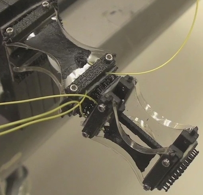
Figure 2a,b shows complete first and second generation bender modules, respectively, each weighing 3.2 g. A bender module requires two linear DEAs and a structure to maintain tension in the linear DEAs and transmit their actuation forces to external loads. Note that for testing purposes, each bender module shown has one active and one passive bowtie linear DEA. Conductive grease applied to only one bowtie linear DEA minimizes fabrication time and still enables proof of principle demonstrations.
As the focus of this paper is a new actuation method for modular robotics, modules consist of only the structure and DEAs. The development of a module with sensing, communication and processing capabilities is left for future work. The DEAs require a voltage on the order of 1000s of volts. Future systems may use a small DC-DC converters (e.g., the 1.7 cm AH60 by EMCO Corp.). For the experiments reported here, we use an off-board DC-DC converter (H101P, EMCO Corp.).
3.1. DEA Linear Actuator
We realize DEA linear actuators using the dielectric elastomer minimum energy structure (DEMES) method first proposed by Kofod et al. [54]. A DEMES consists of a prestrained elastomer attached to a compliant frame surrounding an active area that relaxes to a minimum energy shape upon release. When a voltage is applied across the active area, the elastomer expands in-plane and the structure moves to a new minimum energy shape.
It is known that prestrain acrylic elastomer improves performance by increasing the dielectric breakdown strength [17], reducing the voltage required to achieve a given electric field and increasing the stiffness of the elastomer (due to strain stiffening). We first biaxially prestrained an acrylic-based elastomer (VHB4905 or 4910, 3M Corp.) with a stretching device (similar to Plante’s [55]), shown in Figure 4. The biaxial prestrain is 400% in each direction. A DEA device consists of the prestrained elastomer sandwiched between 12.7 μm-thick and 51 μm-thick polyester frames. Compressing these frames to either side of the VHB attaches them, as the VHB is a double-sided adhesive elastomer. The devices remain under compression for at least 24 hours. The polyester frame starts out rectangular. Upon releasing the device and constraining it (Figure 2a or Figure 2b), the device takes the shape of a bowtie when viewed from above (Figure 2c).
Figure 4.
The biaxial stretching device with several device prototype shapes.

Carbon conductive grease (MG Chemicals) forms the compliant electrodes. We apply the grease to each side of the elastomer by painting it on with a fine brush. Solid-core 30 gauge wire connects each greased side to the output of the DC-DC converter.
3.2. Structure
We developed two module generations. The first generation module structure consists of a polypropylene arm with a living hinge [56] rotational joint. Experiments with this module generation showed a small amount of bending (5). The second generation uses a 0.79-mm diameter dowel pin for the joint, that resulted in over 10 of bending. Plastic components fastened with small screws clamp the DEA bowtie at either end of the bender module. Modules bond to others using Dual Lock Reversible Fasteners (3M Corp.)
3.3. Batch Fabrication
The majority of module components use batch fabrication methods. This enables rapid empirical exploration, as well as larger scale manufacture. Figure 4 shows laser cut polyester templates, one above and one below the prestrained elastomer. Cutting the thin polyester film on medium-density fiberboard minimized sticking from the polyester, which eases the release from the support material. The ABS structural components are also laser cut, and the polypropylene arms with living hinges are machined.
Table 2.
Performance of linear actuator prototypes. Abbreviations used: device length in actuation direction without applied voltage, L; actuation stroke, s; actuation strain, γ; load mass, ; and device mass, .
| Force to | Specific | ||||||
|---|---|---|---|---|---|---|---|
| L | s | γ | Weight | Work | |||
| Figure | (mm) | (mm) | (%) | (g) | (m) | (J/kg) | |
| 5(a) | 12 | 6 | 50 | 3.0 | 0.06 | 50 | 2.9 |
| 5(b) | 11 | 6 | 55 | 11.8 | 0.13 | 91 | 5.3 |
| 5(c) | 15 | 5 | 33 | 26.1 | 0.12 | 218 | 10.7 |
| 6(a) | 3 | 1 | 33 | 0.36 | 0.005 | 72 | 0.7 |
| 6(c) | 3 | 1 | 33 | 4.3 | 0.02 | 215 | 2.1 |
4. Experimental Results
This section presents an empirical comparison of DEMES linear actuators. For each device, we hang a mass, such that the device stretches approximately half way between its minimum energy state and its flat state. Applying a voltage causes the elastomer to expand in-plane and lower the mass; removing the voltage causes the elastomer to pull the mass up. In each experiment, we measured the mass and the stroke, the maximum distance the mass raises. The specific actuation work is the work the actuator does on the mass against gravity per device mass.
Table 2 reports the performance of the five linear actuators shown in Figure 5 and Figure 6. In the case of the diamonds (the first three rows in the table), the performance (force-to-weight ratio and specific work output) increases with increasing diamond width and, hence, cross-sectional actuation area. The performance increase is likely due to the corresponding increase in active actuation area and stored elastic energy, while device mass increases to a lesser degree. The device mass will also vary based on the amount of carbon grease applied.
Rows 4 and 5 in Table 2 show that the miniature bowtie-like (Figure 6c) actuator outperforms the miniature diamond (Figure 6a) actuator, though both have the same active area maximum length (10 mm). The bowtie performs better than the diamond, because both achieve the same strain while the bowtie is a factor of four heavier, yet can lift a factor of 12 heavier load. One explanation for the difference is that the bowtie has more active area, which contributes to increasing actuation to a larger degree than increasing the mass. Second, the bowtie is apparently stiffer per device mass while maintaining the same actuation stroke and, hence, can do more work. Thus, we choose to use bowties for the miniature agonist-antagonist bender.
Figure 5.
The dielectric elastomer minimum energy structure (DEMES) diamond actuators. (a)–(c) Devices with zero applied voltage; (d)–(f) devices at maximum voltage.
Figure 5.
The dielectric elastomer minimum energy structure (DEMES) diamond actuators. (a)–(c) Devices with zero applied voltage; (d)–(f) devices at maximum voltage.

Figure 6.
Miniature DEMES actuators. (a,b) The actuation from zero to maximum voltage of a diamond DEMES with a 12.5-mm maximum length. (c,d) The actuation from zero to maximum voltage of a bowtie with a maximum length of 23.5 mm.
Figure 6.
Miniature DEMES actuators. (a,b) The actuation from zero to maximum voltage of a diamond DEMES with a 12.5-mm maximum length. (c,d) The actuation from zero to maximum voltage of a bowtie with a maximum length of 23.5 mm.

The minimum feature size we can cut with the Universal Laser Systems X-660 laser cutter limits miniaturization of the linear DEA. We found that 1 mm is the minimum feature width that can be cut reliably; thin polyester film templates with thinner features tended to tear when removed from the cutting surface. Thus, the devices shown in Figure 6 represent approximately the smallest devices that we can achieve with this methodology. To ease fabrication complexity, we begin our study with a 20-mm length scale bowtie and leave further miniaturization to future work.
4.1. Agonist-Antagonist Bender
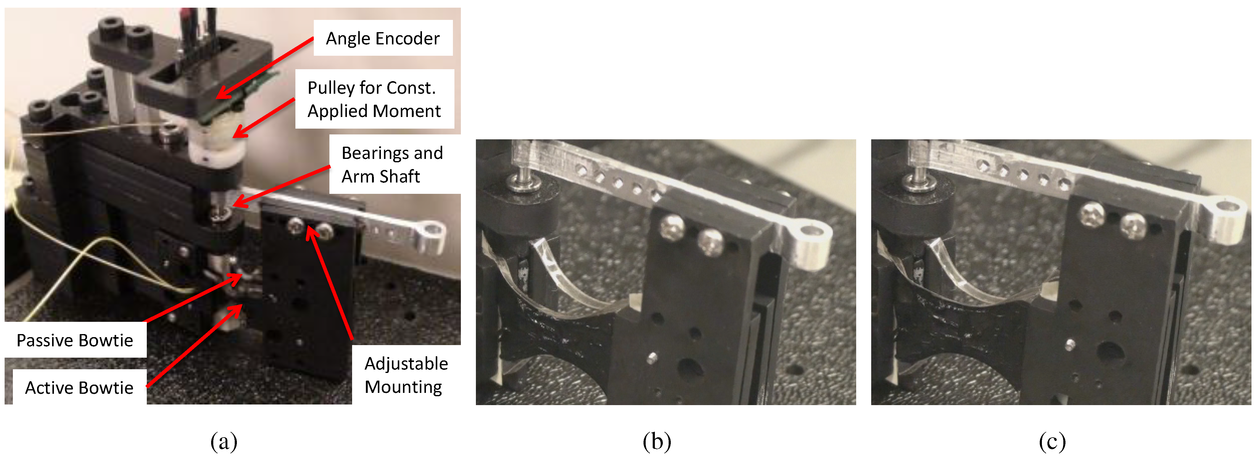
In order to verify that a 20-mm length scale bowtie-based agonist-antagonist bender can achieve sufficiently large bending angles, we built a test apparatus shown in Figure 7a. The apparatus allows us to apply a constant external moment at a given voltage and measure the angular displacement with 0.3 resolution angular encoder. The figure shows one active (greased) and one passive bowtie made with 0.5 mm-thick VHB 4905 elastomer.
Figure 7.
(a) The experimental apparatus for measuring angular displacement as a function of applied moment and voltage. (b,c) The active and passive agonist-antagonist pair of VHB 4905 bowties at 0 and 3 kV.
Figure 7.
(a) The experimental apparatus for measuring angular displacement as a function of applied moment and voltage. (b,c) The active and passive agonist-antagonist pair of VHB 4905 bowties at 0 and 3 kV.
The goal of the experiment is to characterize the applied moment versus displacement behavior of the bender at the maximum operating voltage in order to compare device performance. Figure 8 compares the performance of a VHB 4905 (0.5 mm thick) and a VHB 4910 (1.0 mm thick) benders.
The characterization begins by recording the initial angle of the bender; the angles reported in Figure 8 represent displacement from this initial angle. Next, we apply a maximum operating voltage to the active (greased) bowtie. The maximum operating voltage is set just below the voltage that causes wrinkling in the elastomer, which can lead to failure [30]. Applying this voltage causes the bender to move to its maximum, moment free displacement (e.g., 12 for VHB 4905). Next, we apply an incrementally increasing external moment and measure the angular displacement. The external moment is then decreased in the same increments in order to determine the level of hysteresis. The arrows in Figure 8 indicate the loading and unloading path.
The relative performance of VHB 4910 compared to VHB 4905 is consistent with theory. According to the agonist-antagonist bender model developed by Lochmatter et al. [18], the stall torque . Thus, we expect a two-fold increase in the stall torque by increasing both the voltage and the thickness two-fold in going from VHB 4905 to VHB 4910. Indeed, we observe approximately a two-fold increase in stall torque (measured at ): Nmm for VHB 4905 and Nmm for VHB 4910.
Figure 8.
The angle versus applied moment for the bender shown in Figure 7b,c.
Figure 8.
The angle versus applied moment for the bender shown in Figure 7b,c.

Note that the maximum moment free displacement for both actuators is approximately the same, which is also consistent with theory. For small strains significantly less than 30%, the actuation strain in the elastomer thickness direction z, [15] , where Y is the modulus of elasticity. This actuation strain, in turn, determines the angular displacement of the bender [18]. Because in both experiments plotted in Figure 8, the initial electric field remains constant, we expect and indeed observe no significant change in the maximum moment free angular displacement. For the regions with larger strains, non-linear effects apply and are one source of error for our model.
4.2. Demonstrations
In order to demonstrate the feasibility of DEAs for modular robotics, we performed two sets of experiments with a pair of bender modules. In the first experiment, we demonstrate actuation of two modular robot configurations. In the second experiment, we demonstrate that two modules acting in parallel can lift a larger load compared to one module. The three demonstrations shown here were performed with both module generations. We present configurations comprising second generation modules, which use VHB 4905 and achieve the largest angular displacements.
Figure 9a shows the first configuration. Each module has its rotation axis perpendicular to gravity. Each module is wired to the same DC-DC converter. For each bender module, increasing the voltage from 0 V to 3,500 V causes the active bowtie to expand, allowing the passive bowtie to relax. This combination causes each module to bend from the 0 V state (Figure 9a) to the 3,500 V state (Figure 9b).
To demonstrate the modular nature of the system, we manually reconfigured the 2 DOF modular robot arm in Figure 9 to the configuration in Figure 10. Again, we apply 3,500 V across the active bowtie of each bender, and the robot arm moves from the 0 V (Figure 10a) to the 3,500 V (Figure 10b) state.
Figure 9.
Two module configuration, each with the rotation axis perpendicular to gravity at 0 V (a) and 3,500 V (b).
Figure 9.
Two module configuration, each with the rotation axis perpendicular to gravity at 0 V (a) and 3,500 V (b).

Figure 10.
Two module configuration: one with the rotation axis perpendicular to gravity and the other with the rotation axis parallel to gravity at 0 V (a) and 3,500 V (b).
Figure 10.
Two module configuration: one with the rotation axis perpendicular to gravity and the other with the rotation axis parallel to gravity at 0 V (a) and 3,500 V (b).

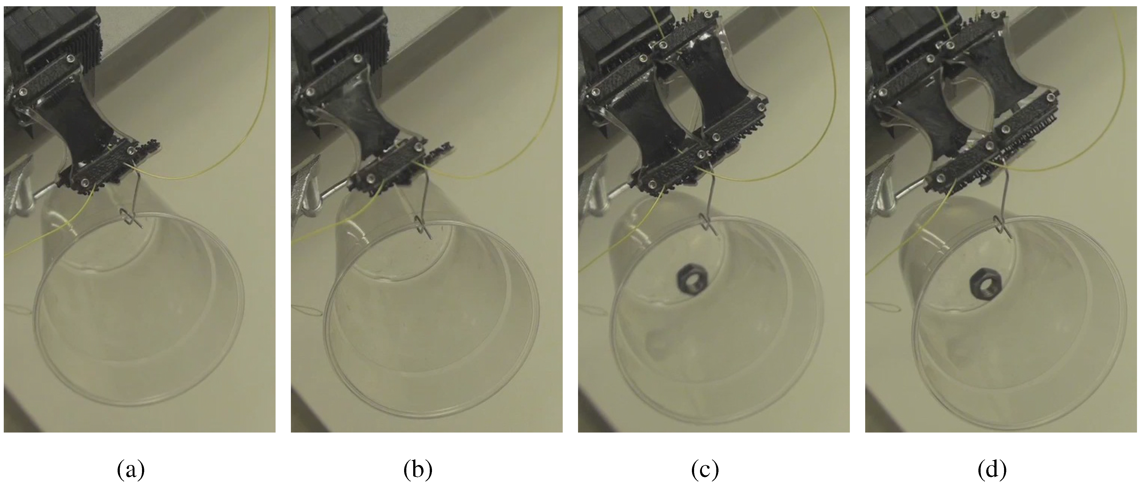
Next, we demonstrate parallel actuation by showing that two modules acting in parallel can lift a larger load than a single module. We perform two experiments depicted in Figure 11. In the first experiment, one module lifts 4.2 g from the 3,500 V state (Figure 11a) to the 0 V state (Figure 11b). In the second experiment, two modules acting in parallel lift 8.9 g from the 3,500 V state (Figure 11c) to the 0 V state (Figure 11d). In both cases, the module(s) move from the same starting angle to ending angle. It is important to note that the natural compliance of the bender modules (a property of most dielectric elastomer actuators) helps them cooperate to lift larger loads. Thus, doubling the number of modules doubles the load that the robot can lift through the same angular region.
Figure 11.
Alone, one module lifts a single nut from the 3,500 V state (a) to the 0 V state (b). Together, two modules lift two nuts from the 3,500 V state (c) to the 0 V state (d).
Figure 11.
Alone, one module lifts a single nut from the 3,500 V state (a) to the 0 V state (b). Together, two modules lift two nuts from the 3,500 V state (c) to the 0 V state (d).

4.3. Observations
Design parameters and failure modes limit the bender’s maximum angular displacement. In the case of design parameters, decreasing the ratio of the distance between the linear actuators and the length of the bender arm will increase the maximum angular displacement [18]. In addition, increasing the prestrain in the direction orthogonal to the bender arm length relative to the prestrain in the bender arm length direction may promote larger actuation strain along the bender arm length and, hence, a larger bending angle [18]. The degree of bending (proportional to actuation strain ) is also limited by the maximum electric field E (as ) before a failure mode occurs. Thus, we operate at the maximum electric field before one of two observed failure modes occurs: dielectric breakdown leading to elastomer tearing and arcing.
With early prototypes, the maximum electric field is limited by dielectric breakdown. In the case of dielectric breakdown, the electric field at some point on the elastomer exceeds the dielectric strength of the elastomer. At this point, a short occurs, causing a hole and typically subsequent tearing of the DEA. We observed this failure mode to occur near the clamped boundary and avoided it in later prototypes by not greasing that area.
Arcing through the air also limits the maximum electric field. Above a certain threshold voltage, arcing occurs between two grease points that are at sufficiently different potentials. We observe frequent arcing with VHB 4910 devices that require 6,000 V to maintain the same actuation strain as a VHB 4905 device (see Section 4.1). Thus, each module in a demonstration configuration uses VHB 4905 and actuates at 3,500 V, and we observe no arcing.
The specific stall torque of a module depends on the module mass and length and the dielectric elastomer actuator parameters. Both generations of modules (Figure 2a,b) have mass 3.2 g and length 30 mm. The first module generation uses VHB 4910, which has a maximum stall torque of 2.4 Nmm, yielding a maximum number of cantilevered modules, , of 1.8. The second generation uses VHB 4905, which has a maximum stall torque of 1.2 Nmm, yielding an of 1.1. Thus, we expect that the module can cantilever one other module. The specific module torques for the first and second generations are 0.75 Nm/kg and 0.38 Nm/kg, respectively.
5. Model
This section presents a model of an antagonistic bender that uses bowtie linear actuators. We refine the antagonistic bender model of Lochmatter et al. [18] to handle the complex deformation of the bowtie. This section comprises: a brief review of the antagonistic bender model (Section 5.1), a description of the refined model (Section 5.2) and the results of fitting the model to data (Section 5.3).
5.1. Model Review
Lochmatter et al. [18] present a model of an antagonistic bender, as shown in Figure 12. A pair of linear actuators denoted by dashed line segments and attach to a rigid ‘T’-shaped frame pinned to the ground at origin. Each linear actuator consists of a biaxially prestrained elastomer sandwiched between compliant electrodes. Applying a voltage across the thickness of the actuator causes an electrostatic force that compresses the elastomer, allowing it to expand in its in-plane directions. As the actuator expands, the unactuated actuator contracts, relaxing its prestrain and doing work against the applied torque load, .
Figure 12.
The model of the antagonistic bender comprises a pair of bowtie actuators (shown as dashed lines) attached to a “T”-shaped frame pinned to ground. The figure shows the bowtie actuated (thus extended) and the unactuated bowtie contracted. The represents the torque load on the actuator. Unit vectors and denote the direction of the bowtie elastic force.

We model the bowtie elastomer as an ideal dielectric elastomer in a state of biaxial stress whose in-plane stress components are given by [57]:
where is the Helmholtz free energy required to stretch the elastomer, and [58]. Equation (2) together with the incompressibility constraint and electric field with initial elastomer thickness define the equations of state for the elastomer.
Since the bowtie elastomer undergoes large strains, we use the non-linear Gent model [59] that accounts for strain stiffening:
where μ is the shear modulus and is the material constant limiting stretch. We use for VHB [58]. The shear modulus μ is set to 55 kPa, the mid-range of values reported in the literature [60].
The polyester frame of the bowtie also adds stiffness to the bowtie actuator. We analyze each of the two deformed edges of the bowtie as an initially curved beam in compression using the pseudo-rigid body method [61]. Analysis with this model shows that the stiffness contribution of the frame is negligible compared to the elastomer stiffness. Thus, the frame stiffness is not modeled as part of the bender model.
5.2. Model Refinement
The antagonistic bender model introduced by Lochmatter et al. [18] assumes that the stretch ratio in the y direction, , remains constant as the length of the actuator in the x direction changes. This assumption is valid, because of the large aspect ratio of the linear actuator where its length in y is much larger than its length in x. In this case, the modeling imperfections from assuming a straight boundary along the edges are negligible. Further, the constant assumption causes the strain field to be uniform in the x and z directions throughout the elastomer.
However, in the case of the bowtie actuator where the aspect ratio is near unity, the effect of deformation in the y direction is not negligible. Consequently, the strain field is not uniform, and the deformation in y contributes to the force balance in x. We refine the antagonistic bender model using the biaxial state of stress defined in Equation (2) with a refinement to account for the complex state of stress in the deformed bowtie.
We model the deformed curves of the edges of the bowtie (see Figure 13a) using piecewise cubic splines. The curve segment between points and is cubic with four boundary conditions to fit the four polynomial coefficients. In its undeformed state, the length of the line segment is , and as it deforms, the straight line distance between and is . The constraints on the cubic (of the form ) are: (1) , (2) , (3) , and (4) , where is the x coordinate of point . This models one quarter of the bowtie curve sections; the remaining curve sections are formed by mirroring the curve about and then mirroring those curves about . This model determines the distance between the two nearest points and of each curved segment of the bowtie shown in Figure 13a.
The complex deformation of the bowtie requires accounting for the varying states of stretch ratios throughout the deformed elastomer. Under the assumption of constant , the stretch ratio in z, . We relax this assumption and add a fitting factor, to account for the varying .
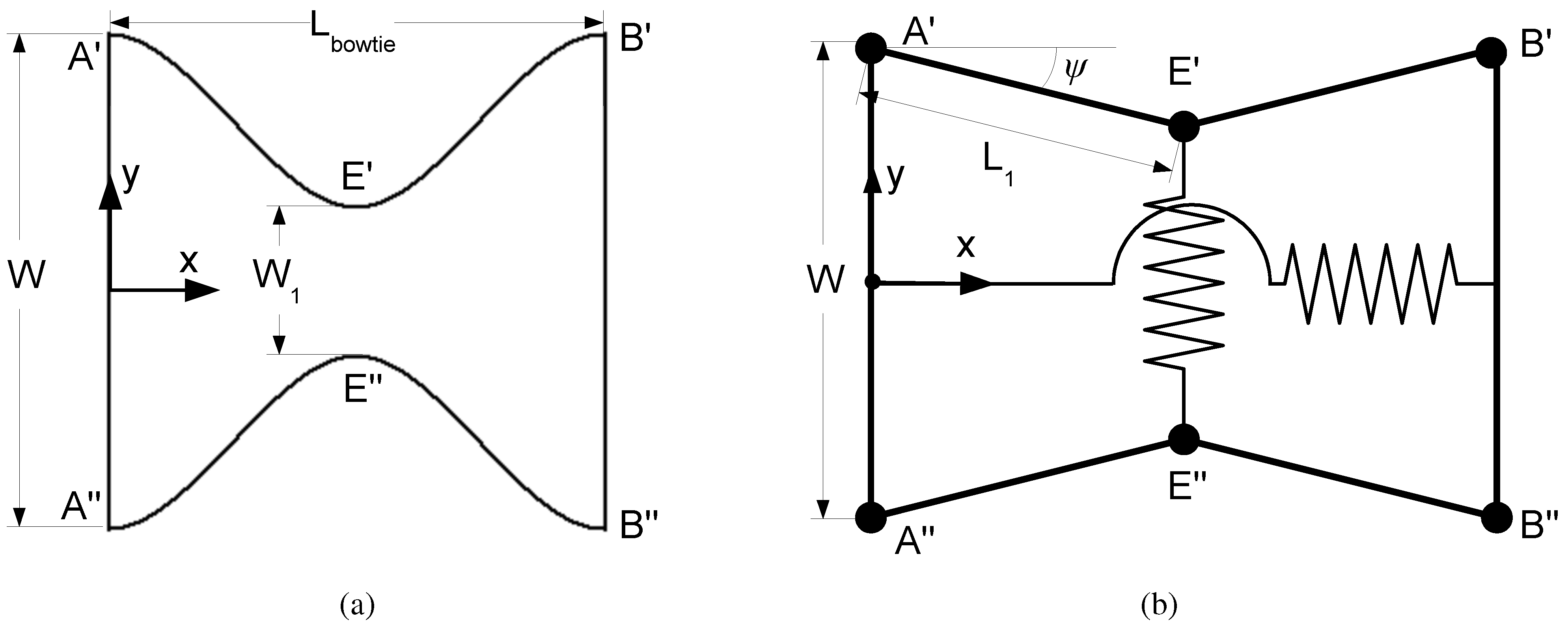
Figure 13.
Deformed bowtie linear actuator (a) when the bender angle . The model of the bowtie (b) is a six bar mechanism with one spring along the x (actuation) direction and one spring in the y direction. The y direction spring couples the deformation in y (change in ) with force in the actuation direction x.

Figure 14 depicts two cases for the bowtie deformation cases: prestrained state (Figure 14a) and an arbitrary linear displacement along x (Figure 14b). When the bowtie is undeformed, the stretch ratios are equivalent to the pre-stretch ratios . As the bowtie contracts in x, increases, but the increase is a function of x and y. The section view in the bottom of Figure 14b shows that as the bowtie contracts along x, the thickness is maximal at the midpoint and decreases in either direction toward the boundaries.
The range of thicknesses is due to the boundary conditions. At either end of the bowtie, the clamped boundary condition constrains . Figure 14 illustrates this effect, showing the gray element in Figure 14a deforms only in x as the bowtie contracts (Figure 14b). Similarly, an element at one of the four corners of the bowtie (, , , ) will remain nearly constant at the pre strain stretch ratios. In the deformed case (Figure 14b), the relaxation of the elastomer (and, hence, the thickness of the elastomer) is greatest at the midpoint where there is the shortest distance between either side of the deformed frame (points and ). At the corners, the relaxation is minimal, and hence, the thickness is minimal.
To account for the variation in elastomer thickness, we model an effective as a linear function of , which is, in turn, a function of the bender angle, θ. We define (as shown in Figure 14), so that at (Figure 14a), . Thus, the expression for the stretch ratio in z is given by:
Section 5.3 demonstrates that using this fitting factor is sufficient to fit the model to data accurately.
The cross-section areas normal to x and y ( and , respectively) used for computing actuator forces from the elastomer stresses ( and , respectively) use the fitted to account for the varying cross-section areas (i.e., and ). We evaluate the cross-section areas at the mid-planes of the bowtie ( and ).
Figure 14.
Undeformed bowtie (a) with the elastomer in the prestrained state with thickness . Deformed bowtie (b) where the elastomer thickness is greatest at the midpoint and lowest at boundaries . denotes displacement from prestrained state. Each top view of the bowtie actuator has accompanying section view .

Figure 13b depicts the simplified model of the bowtie deformation. The springs in the figure represent the elastic force of the elastomer on the six bar mechanism model. We assume the elastic force in y acts at a single point on each deformed edge of the bowtie (points and ). Considering the free body diagram on bowtie segment , the actuation force in the negative x direction balances with x spring force and the force at each joint ( and ). The force balance for the actuation force along in Figure 12 on the bowtie segment is given by:
where we evaluate the states of stress at the bowtie mid-planes using Equation (2).
In Equation (2), we evaluate the stretch states at the bowtie mid-planes:
where and are the original (before pre-stretch) lengths of the elastomer in the x and y directions, respectively.
Note that the second term in Equation (5) couples the deformation in y to the actuation force balance. Furthermore, the evaluation of the stresses and stretch ratios at the bowtie mid-planes and the assumption of a single global as a linear function are simplifications of the complex state of strain in the deformed elastomer. The expression for the actuation force along in Figure 12 follows the same method as the derivation using the geometry of the bowtie between C and D.
Finally, the moment balance between the applied torque load and moments due to the and bowties is given by:
where and are the positions with respect to origin of the points B and D, respectively. The bowtie actuation forces and act along unit vectors and , respectively.
5.3. Model Fit to Data
We use two data sets to fit the model parameter . We use a shear modulus kPa that is within the mid-range of reported values for VHB [60]. Using the constrained optimization package in MATLAB, we determine the the value of that minimizes the sum of squared errors normalized by the total sum of squares.
In the first data set (shown in Figure 15), the bender has a single bowtie between C and D. This enables characterization of the stiffness of the bowtie in a constrained configuration. Without the bender constraining either end of the bowtie ( and where C and D replace A and B in Figure 15), the bowtie tends to twist about about the x axis as it contracts.
Figure 15.
Model fit to data for a single bowtie bender.

In the experiment, we allow the single bowtie bender to come to equilibrium, which is at , as shown in Figure 15. We then apply a moment, , using the apparatus shown in Figure 7a, increasing it from 0 to Nmm and then decreasing it in the same increments. The observed hysteresis is negligible, and the error bar at each data point shown in Figure 15 represents the confidence interval for all measured angles at the corresponding applied moment. The figure plots the data versus the fitted model. In the single bowtie bender case, the actuation force , since that bowtie is not used. The coefficient of determination value indicates that the model fits the data well.
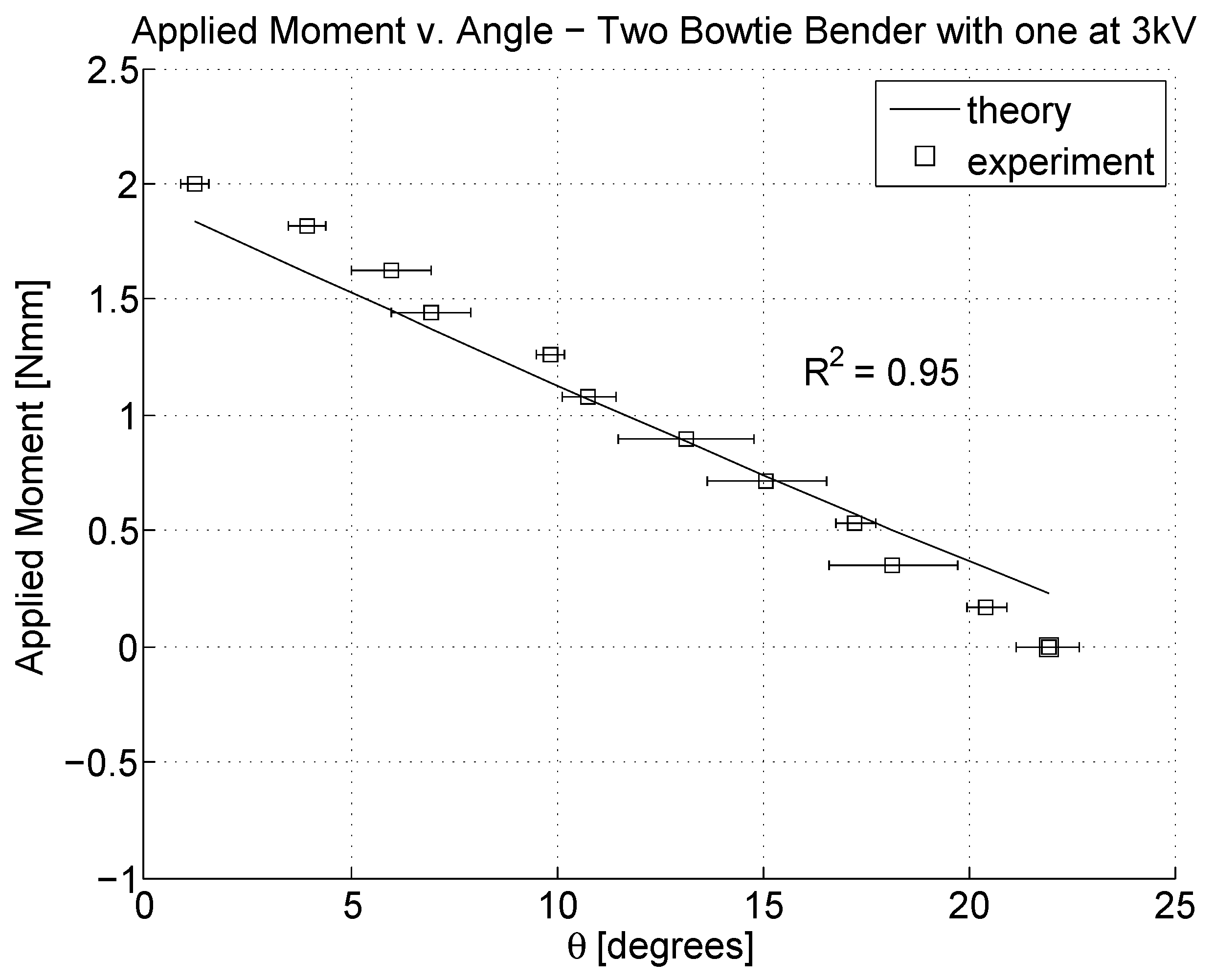
The second data set uses the VHB 4905 actuated data plotted in Figure 8. The experiment is similar to the single bowtie bender case, except that there are two bowties and one () is actuated at 3 kV. Section 4.1 describes the experiment in detail. Figure 16 plots the data versus the fitted model. As in the single bowtie bender case, each error bar indicates the confidence interval on all angle measurements at a given applied moment. Again, the high coefficient of determination indicates that the model fits the data.
Therefore, the comparison of data and the fitted model shows that, using only one fitting parameter, the model fits the data well. The fit value for these data is . The value for gives the slope of the curve that maps displacement from prestrained state to effective . The value is consistent in that indeed increases as increases. Furthermore, for all angular displacements of the bender tested, the value for yields a that is within the bounds of the maximum and minimum local over the entire bowtie.
Figure 16.
Model fit to data for a two bowtie bender.

6. Conclusions
This paper presents the design and implementation of a miniaturized module actuator based on a bowtie DEA bender along with a model that predicts performance. This demonstrates the feasibility of a DEA-based modular robot.
We show that DEAs are a promising actuation technology for a miniature module because of their high specific torque and potential for high strain compared to other actuation technologies. We experimentally investigate different linear actuator morphologies and demonstrate a bender that can achieve up to 15 of bending. The agonist-antagonist bender is 20 mm in length, which is one-seventh the scale of the device demonstrated by Lochmatter et al. [18] and achieves a ten-fold specific torque improvement.
Demonstrations with multiple modules show several actuating modular robot arm configurations, including one that uses two modules in parallel to lift a load double the amount of a single module.
Modeling results show the ability to fit a model to the data of the complex 3D deformation of a DEMES bowtie actuator. The novel bowtie model presented accounts for the deformation of the bowtie linear actuator perpendicular to the useful actuation direction. The model achieves this by assuming that the bowtie is a six bar mechanism with one spring in the actuation direction and one spring perpendicular to the actuation direction, coupling that deformation to the actuation direction. The model uses a parameter that accounts for the non-uniform stretch state throughout the deformed elastomer. Intuitively, the effect of the bowtie shape is to have the areas that are towards the outer ends contribute more force than the portions toward the inside that are more deformed, correlating with the thickness of the elastomer. Results show that this model fits both single-bowtie and actuated, two-bowtie bender data well. Given the accuracy of this model, it is possible that the methodology of using the varying thickness of the material as a modifier can accurately predict the performance of arbitrarily-shaped DEMES actuators, including diamond and other shapes.
Within DEAs, the ideal actuator form would be a joint that can both rotate and extend; this combination of rotational and prismatic DOF would reduce the number of total joints required to achieve desirable motion. Many groups have demonstrated DEAs of various forms that have either a prismatic degree of freedom that can extend [62] or compress [63]; others have demonstrated DEAs that have multiple DOF that can either both extend and expand radially, as in [64], or can both extend and bend [35]. Our previous work [1] shows 1D parallel actuation: a single row of modules can work in parallel to increase the total force output of the robot. However, achieving 2D parallel actuation requires modules with a translational degree of freedom. It is possible to modify the agonist-antagonist configuration with a flexible internal connection to allow for a prismatic DOF, but we leave this to future work.
Other future work includes finding optimal shapes by exploring the modeling methodology presented, improving the cycle time before failure of the actuator by using a different electrode material [65] or by adding multiple layers to the dielectric [66] to add robustness, as well as to do demonstrations of other robotic actions and self-reconfiguration.
References
- White, P.J.; Latscha, S.; Schlaefer, S.; Yim, M. Dielectric elastomer bender actuator applied to modular robotics. In Proceedings of the 2011 IEEE/RSJ International Conference on Intelligent Robots and Systems (IROS), San Francisco, CA, USA, 25–30 September 2011; pp. 408–413.
- Campbell, J.; Pillai, P. Collective actuation. Int. J. Robot. Res. 2008, 27, 299–314. [Google Scholar] [CrossRef]
- Krishnan, M.; Tolley, M.; Lipson, H.; Erickson, D. Hydrodynamically Tunable Affinities for Fluidic Assembly. Langmuir 2009, 25, 3769–3774. [Google Scholar] [CrossRef] [PubMed]
- Neubert, J.; Cantwell, A.; Constantin, S.; Kalontarov, M.; Erickson, D.; Lipson, H. A Robotic Module for Stochastic Fluidic Assembly of 3D Self-Reconfiguring Structures. In Proceedings of the IEEE/RSJ IEEE International Conference on Robotics and Automation, Anchorage, AK, USA, 3–7 May 2010; pp. 2479–2484.
- Gilpin, K.; Knaian, A.; Rus, D. Robot Pebbles: One Centimeter Modules for Programmable Matter through Self-Disassembly. In Proceedings of the IEEE International Conference on Robotics and Automation (ICRA), Anchorage, AK, USA, 3–7 May 2010.
- Donald, B.R.; Levey, C.G.; Paprotny, I. Planar Microassembly by Parallel Actuation of MEMS Microrobots. J. Microelectromechanical Syst. 2008, 17, 789–808. [Google Scholar] [CrossRef]
- Pawashe, C.; Floyd, S.; Sitti, M. Assembly and Disassembly of Magnetic Mobile Micro-Robots towards 2-D Reconfigurable Micro-Systems. In Proceedings of the International Symposium on Robotics Research, Lucerne, Switzerland, 31 August–3 September 2009.
- White, P.J.; Posner, M.L.; Yim, M. Strength Analysis of Miniature Folded Right Angle Tetrahedron Chain Programmable Matter. In Proceedings of the IEEE/RSJ International Conference on Robotics and Automation, Anchorage, AK, USA, 3–7 May 2010; pp. 2785–2790.
- Yoshida, E.; Murata, S.; Kokaji, S.; Kamimura, A.; Tomita, K.; Kurokawa, H. Get Back in Shape! A hardware prototype self-reconfigurable modular microrobot that uses shape memory alloy. IEEE Robot. Autom. Mag. 2002, 9, 54–61. [Google Scholar]
- Hawkes, E.; An, B.; Benbernou, N.; Tanaka, H.; Kim, S.; Demaine, E.; Rus, D.; Wood, R. Programmable matter by folding. Proc. Natl. Acad. Sci. USA 2010, 107, 12441. [Google Scholar] [CrossRef] [PubMed]
- Karagozler, M.E.; Goldstein, S.C.; Reid, J.R. Stress-Driven MEMS Assembly + Electrostatic Forces = 1 mm Diameter Robot. In Proceedings of the IEEE/RSJ International Conference on Intelligent Robots and Systems, Louis, MO, USA, 11–15 October 2009.
- Nagy, Z.; Flückiger, M.; Oung, R.; Kaliakatsos, I.; Hawkes, E.; Nelson, B.; Harada, K.; Susilo, E.; Menciassi, A.; Dario, P.; et al. Assembling reconfigurable endoluminal surgical systems: opportunities and challenges. Int. J. Biomechatronics Biomed. Robot. 2009, 1, 3–16. [Google Scholar] [CrossRef]
- Pfeifer, R.; Bongard, J.; Grand, S. How the Body Shapes the Way We Think: A New View of Intelligence; The MIT Press: Cambridge, MA, USA, 2007. [Google Scholar]
- OHalloran, A.; OMalley, F.; McHugh, P. A review on dielectric elastomer actuators, technology, applications, and challenges. J. Appl. Phys. 2008, 104, 071101–071101. [Google Scholar] [CrossRef]
- Carpi, F.; De Rossi, D.; Kornbluh, R.; Pelrine, R.; Sommer-Larsen, P. Dielectric Elastomers as Electromechanical Transducers; Elsevier Amsterdam: Oxford, UK, 2008. [Google Scholar]
- Pelrine, R.; Kornbluh, R.; Joseph, J.; Heydt, R.; Pei, Q.; Chiba, S. High-field deformation of elastomeric dielectrics for actuators. Mater. Sci. Eng. C 2000, 11, 89–100. [Google Scholar] [CrossRef]
- Pelrine, R.; Kornbluh, R.; Pei, Q.; Joseph, J. High-speed electrically actuated elastomers with strain greater than 100%. Science 2000, 287, 836. [Google Scholar] [CrossRef] [PubMed]
- Lochmatter, P.; Kovacs, G. Design and characterization of an active hinge segment based on soft dielectric EAPs. Sens. Actuators A Phys. 2008, 141, 577–587. [Google Scholar] [CrossRef]
- White, P.J.; Yim, M. Scalable Modular Self-reconfigurable Robots Using External Actuation. In Proceedings of the IEEE/RSJ International Conference on Intelligent Robots and Systems, San Diego, CA, USA, 29 October–2 November 2007; pp. 2773–2778.
- Støy, K.; Brandt, D.; Christensen, D.J. Self-Reconfigurable Robots—An Introduction; MIT Press: Cambridge, MA, USA, 2010. [Google Scholar]
- Murata, S.; Yoshida, E.; Tomita, K.; Kurokawa, H.; Kamimura, A.; Kokaji, S. Hardware design of modular robotic system. In Proceedings of the IEEE/RSJ International Conference on Intelligent Robots and Systems, Takamatsu, Japan, 31 October–5 November 2000; Volume 3, pp. 2210–2217.
- Yim, M. Locomotion with a Unit Modular Reconfigurable Robot. PhD Thesis, Stanford University, Stanford, CA, USA, 1994. [Google Scholar]
- Components, N.D. Nitinol SM495 Wire, 2011. Available online: http://www.nitinol.com/media/files/material-properties-pdfs/sm495_wire_data[Converted]_v2.pdf (accessed on 21 July 2014).
- Kornbluh, R.; Pelrine, R.; Joseph, J.; Pei, Q.; Chiba, S. Ultra-high strain response of elastomeric polymer dielectrics. In Proceedings of the Materials Research Society Symposium, Boston, MA, USA, 27 November–1 December 2000; Volume 600, pp. 119–130.
- Bar-Cohen, Y. Electroactive Polymer (EAP) Actuators as Artificial Muscles: Reality, Potential, and Challenges; SPIE Press: Bellingham, WA, USA, 2004. [Google Scholar]
- Cross, L.; Ma, W. Recent Progress in High Strain Electroactive Actuator Materials. In Proceedings of the Thirteenth International Conference on Adaptive Structures and Technologies, Potsdam, Berlin, Germany, 7–9 October 2003; p. 3.
- Instrumente, P. Miniature Multilayer Piezo Stack Actuators, 2011. Available online: http://www.physikinstrumente.com/en/pdf/PL022_Datasheet.pdf (accessed on 21 July 2014).
- Wood, R.; Steltz, E.; Fearing, R. Optimal energy density piezoelectric bending actuators. Sens. Actuators A Phys. 2005, 119, 476–488. [Google Scholar] [CrossRef]
- Faulhaber. Brushless DC-Micromotors Series 0206, 2011. Available online: http://www.micromo.com/uploadpk/0206_B_DFF.pdf (accessed on 28 March 2011).
- Plante, J.; Dubowsky, S. Large-scale failure modes of dielectric elastomer actuators. Int. J. Solids Struct. 2006, 43, 7727–7751. [Google Scholar] [CrossRef]
- Bertoldi, K.; Gei, M. Instabilities in multilayered soft dielectrics. J. Mech. Phys. Solids 2011, 59, 18–42. [Google Scholar] [CrossRef]
- Rudykh, S.; Bhattacharya, K.; deBotton, G. Multiscale instabilities in soft heterogeneous dielectric elastomers. Proc. R. Soc. A Math. Phys. Eng. Sci. 2014, 470, 20130618. [Google Scholar] [CrossRef] [PubMed]
- Rudykh, S.; Bhattacharya, K.; deBotton, G. Snap-through actuation of thick-wall electroactive balloons. Int. J. Linear Mech. 2012, 47, 206–209. [Google Scholar] [CrossRef]
- Kornbluh, R.; Pelrine, R. High-performance acrylic and silicone elastomers. In Dielectric Elastomers as Electromechanical Transducers: Fundamentals, Materials, Devices, Models and Applications of an Emerging Electroactive Polymer Technology; Publisher: Oxford, UK, 2008. [Google Scholar]
- Pei, Q.; Rosenthal, M.; Stanford, S.; Prahlad, H.; Pelrine, R. Multiple-degrees-of-freedom electroelastomer roll actuators. Smart Mater. Struct. 2004, 13, N86. [Google Scholar] [CrossRef]
- Christensen, D.; Campbell, J.; Støy, K. Anatomy-based organization of morphology and control in self-reconfigurable modular robots. Neural Comput. Appl. 2010, 19, 787–805. [Google Scholar] [CrossRef]
- Jordi, C.; Michel, S.; Kovacs, G.; Ermanni, P. Scaling of planar dielectric elastomer actuators in an agonist-antagonist configuration. Sens. Actuators A Phys. 2010, 161, 182–190. [Google Scholar] [CrossRef]
- Arruda, E.M.; Boyce, M.C. A three-dimensional constitutive model for the large stretch behavior of rubber elastic materials. J. Mech. Phys. Solids 1993, 41, 389–412. [Google Scholar] [CrossRef]
- Bergström, J.; Boyce, M. Constitutive modeling of the large strain time-dependent behavior of elastomers. J. Mech. Phys. Solids 1998, 46, 931–954. [Google Scholar] [CrossRef]
- Chouinard, P.; Plante, J. Bistable antagonistic dielectric elastomer actuators for binary robotics and mechatronics. Mechatron. IEEE ASME Trans. 2012, 17, 857–865. [Google Scholar] [CrossRef]
- Li, T.; Keplinger, C.; Baumgartner, R.; Bauer, S.; Yang, W.; Suo, Z. Giant voltage-induced deformation in dielectric elastomers near the verge of snap-through instability. J. Mech. Phys. Solids 2013, 61, 611–628. [Google Scholar] [CrossRef]
- Gei, M.; Springhetti, R.; Bortot, E. Performance of soft dielectric laminated composites. Smart Mater. Struct. 2013, 22, 104014. [Google Scholar] [CrossRef]
- Toupin, R.A. The elastic dielectric. J. Ration. Mech. Anal. 1956, 5, 849–915. [Google Scholar] [CrossRef]
- Dorfmann, A.; Ogden, R. Nonlinear electroelasticity. Acta Mech. 2005, 174, 167–183. [Google Scholar] [CrossRef]
- Bustamante, R.; Dorfmann, A.; Ogden, R. Nonlinear electroelastostatics: A variational framework. Z. Angew. Math. Phys. 2009, 60, 154–177. [Google Scholar] [CrossRef]
- Henann, D.L.; Chester, S.A.; Bertoldi, K. Modeling of dielectric elastomers: Design of actuators and energy harvesting devices. J. Mech. Phys. Solids 2013, 61, 2047–2066. [Google Scholar] [CrossRef]
- Kofod, G.; Sommer-Larsen, P. Silicone dielectric elastomer actuators: Finite-elasticity model of actuation. Sens. Actuators A Phys. 2005, 122, 273–283. [Google Scholar] [CrossRef]
- Wissler, M. Modeling Dielectric Elastomer Actuators. PhD Thesis, Swiss Federal Institute of Technology, Zurich, Switzerland, 2007. [Google Scholar]
- Zhao, X.; Suo, Z. Method to analyze programmable deformation of dielectric elastomer layers. Appl. Phys. Lett. 2008, 93, 251902. [Google Scholar] [CrossRef]
- Zhou, J.; Hong, W.; Zhao, X.; Zhang, Z.; Suo, Z. Propagation of instability in dielectric elastomers. Int. J. Solids Struct. 2008, 45, 3739–3750. [Google Scholar] [CrossRef]
- O’Brien, B.; Calius, E.; Xie, S.; Anderson, I. An experimentally validated model of a dielectric elastomer bending actuator. In Proceedings of the 15th International Symposium on: Smart Structures and Materials & Nondestructive Evaluation and Health Monitoring, International Society for Optics and Photonics, San Diego, CA, USA, 9 March 2008; pp. 69270T–69270T.
- O’Brien, B.; McKay, T.; Calius, E.; Xie, S.; Anderson, I. Finite element modelling of dielectric elastomer minimum energy structures. Appl. Phys. A Mater. Sci. Process. 2009, 94, 507–514. [Google Scholar] [CrossRef]
- Zhang, R.; Kunz, A.; Lochmatter, P.; Kovacs, G. Dielectric Elastomer Spring Roll Actuators for a Portable Force Feedback Device. In Proceedings of the 14th Symposium on Haptic Interfaces for Virtual Environment and Teleoperator Systems, Alexandria, VA, USA, 25–26 March 2006; pp. 347–353.
- Kofod, G.; Paajanen, M.; Bauer, S. New design concept for dielectric elastomer actuators. Proc. SPIE 2006, 6168. [Google Scholar] [CrossRef]
- Plante, J. Dielectric Elastomer Actuators for Binary Robotics and Mechatronics. PhD Thesis, Massachusetts Institute of Technology, Cambridge, MA, USA, 2006. [Google Scholar]
- Howell, L. Compliant Mechanisms; Wiley-Interscience: New York, NY, USA, 2001. [Google Scholar]
- Suo, Z. Theory of dielectric elastomers. Acta Mech. Solida Sin. 2010, 23, 549–578. [Google Scholar] [CrossRef]
- Kollosche, M.; Zhu, J.; Suo, Z.; Kofod, G. Complex interplay of nonlinear processes in dielectric elastomers. Phys. Rev. E 2012, 85, 051801. [Google Scholar] [CrossRef]
- Gent, A. A new constitutive relation for rubber. Rubber Chem. Technol. 1996, 69, 59–61. [Google Scholar] [CrossRef]
- Lu, T.; Huang, J.; Jordi, C.; Kovacs, G.; Huang, R.; Clarke, D.R.; Suo, Z. Dielectric elastomer actuators under equal-biaxial forces, uniaxial forces, and uniaxial constraint of stiff fibers. Soft Matter 2012, 8, 6167–6173. [Google Scholar] [CrossRef]
- Edwards, B.T.; Jensen, B.D.; Howell, L.L. A pseudo-rigid-body model for initially-curved pinned-pinned segments used in compliant mechanisms. J. Mech. Des. 2001, 123, 464–468. [Google Scholar] [CrossRef]
- Lacour, S.P.; Prahlad, H.; Pelrine, R.; Wagner, S. Mechatronic system of dielectric elastomer actuators addressed by thin film photoconductors on plastic. Sens. Actuators A Phys. 2004, 111, 288–292. [Google Scholar] [CrossRef]
- Carpi, F.; Salaris, C.; De Rossi, D. Folded dielectric elastomer actuators. Smart Mater. Struct. 2007, 16, S300. [Google Scholar] [CrossRef]
- Carpi, F.; Migliore, A.; Serra, G.; De Rossi, D. Helical dielectric elastomer actuators. Smart Mater. Struct. 2005, 14, 1210. [Google Scholar] [CrossRef]
- Yuan, W.; Brochu, P.; Zhang, H.; Jan, A.; Pei, Q. Long lifetime dielectric elastomer actuators under continuous high strain actuation. In Proceedings of the 16th International Symposium on: Smart Structures and Materials & Nondestructive Evaluation and Health Monitoring, International Society for Optics and Photonics, San Diego, CA, USA, 8 March 2009; pp. 72870O–72870O.
- Schlaak, H.; Jungmann, M.; Matysek, M.; Lotz, P. Novel multilayer electrostatic solid state actuators with elastic dielectric (Invited Paper). Proc. SPIE 2005, 5759, 121. [Google Scholar]
© 2014 by the authors; licensee MDPI, Basel, Switzerland. This article is an open access article distributed under the terms and conditions of the Creative Commons Attribution license (http://creativecommons.org/licenses/by/3.0/).
Share and Cite
MDPI and ACS Style
White, P.; Latscha, S.; Yim, M. Modeling of a Dielectric Elastomer Bender Actuator. Actuators 2014, 3, 245-269. https://doi.org/10.3390/act3030245
AMA Style
White P, Latscha S, Yim M. Modeling of a Dielectric Elastomer Bender Actuator. Actuators. 2014; 3(3):245-269. https://doi.org/10.3390/act3030245
Chicago/Turabian StyleWhite, Paul, Stella Latscha, and Mark Yim. 2014. "Modeling of a Dielectric Elastomer Bender Actuator" Actuators 3, no. 3: 245-269. https://doi.org/10.3390/act3030245