Development of a Paper Actuator with PEDOT:PSS Thin-Films as An Electrode

1
Nanosystem Research Institute (NRI), National Institute of Advanced Industrial Science and Technology (AIST), Central 5-2, 1-1-1 Higashi, Tsukuba 305-8565, Japan
2
Department of Applied Physics, Graduate School of Engineering, Osaka University, Yamadaoka, Suita-city, Osaka, 565-0871, Japan
*
Author to whom correspondence should be addressed.
Actuators 2014, 3(4), 285-292; https://doi.org/10.3390/act3040285
Submission received: 7 August 2014
/
Revised: 28 November 2014
/
Accepted: 1 December 2014
/
Published: 9 December 2014
Abstract
:A paper actuator was fabricated from poly(3,4-ethylenedioxythiophene) doped with poly(4-styrenesulfonate) (PEDOT:PSS) by a wet process without organic solvents. The paper actuator had a capacitor structure, with a cationic polymer as an insulating layer sandwiched between two PEDOT:PSS films as the electrodes. The thickness of the paper actuator was approximately 36 μm. We measured its displacement as a function of applied voltage and frequency; the maximum displacement was 2.2 mm at 1.5 V and 1 Hz.
1. Introduction
Electroactive polymers (EAPs) have been intensively investigated for many applications, including as acoustic transducers, medical devices, actuators, artificial muscles, sensors, and soft robots [1,2,3,4,5,6]. Under an applied external electric input, EAPs change shape or size. They are soft, flexible, lightweight, and can be easily shaped by trimming. Furthermore, EAPs are easily miniaturized, and have been applied as small actuators in microelectromechanical systems (MEMS) and micro total analysis systems (μTAS). EAPs are generally classified into either electronic or ionic types. The driving mechanism of the electronic EAP is the Coulomb force, including ferroelectric forces, dielectric, and electrostatic interactions [7,8]. In contrast, ionic EAPs change shape by the movement of ions between two electrodes [9,10]. The force of the electronic EAPs is stronger than that of ionic EAPs, and the driving frequency are higher as well. However, electronic EAPs require high driving voltages compared to ionic EAPs. In addition, ionic EAPs are more easily miniaturized owing to their structure and low voltage requirements. Therefore, the development of ionic EAPs is necessary, especially for use as small actuators in MEMS and μTAS applications.
Many types of ionic EAPs have been studied, for example, ionic polymer–metal composites (IPMCs), polymer gels, conductive polymers, and carbon nanotubes. The IPMC is a typical ionic EAP, which works as an actuator at low applied voltages (1–5 V) [11,12,13,14]. The IPMC comprises an ion-exchange polymer membrane that contains mobile ions, coated on either side by two Pt electrodes. The IPMC actuator bends to the anode side when a low voltage is applied, and returns to its original position as the voltage is removed. Generally, Nafion has been adopted as the ion-exchange membrane, and hydrated cations move toward the cathode side when a voltage is applied. As a result, the water content in the chathode side exceeds that in the anode side, and the IPMC bends owing to the differential water content between the two. Although IPMCs have attracted significant attention, their assembly is not without difficulty. The Pt electrode of the IPMC is constructed by chemical plating, but the plating operation must be repeated several times to form a sufficiently thick electrode. Therefore, the IPMC manufacturing process is both lengthy and complicated.
In this study, we propose a novel paper actuator that helps in the easier and safer fabrication of an ionic EAP. This EAP can be manufactured by a wet process without organic solvents. In addition, the novel actuator was significantly thinner than the IPMC. Poly(3,4-ethylenedioxythiophene):poly(styrene sulfonate) (PEDOT:PSS) was selected as the electrode material for the actuator. Films can be easily manufactured by the casting and evaporation of the commercially available PEDOT:PSS aqueous solution. In addition, a cationic polymer was selected as the insulating layer between the anionic PEDOT:PSS electrodes. When the polymer solution was cast on the PEDOT:PSS film, the cationic polymer chain functioned as a glue. The assembled paper actuator was assessed as a function of the applied voltage and frequency.
2. Experimental Section
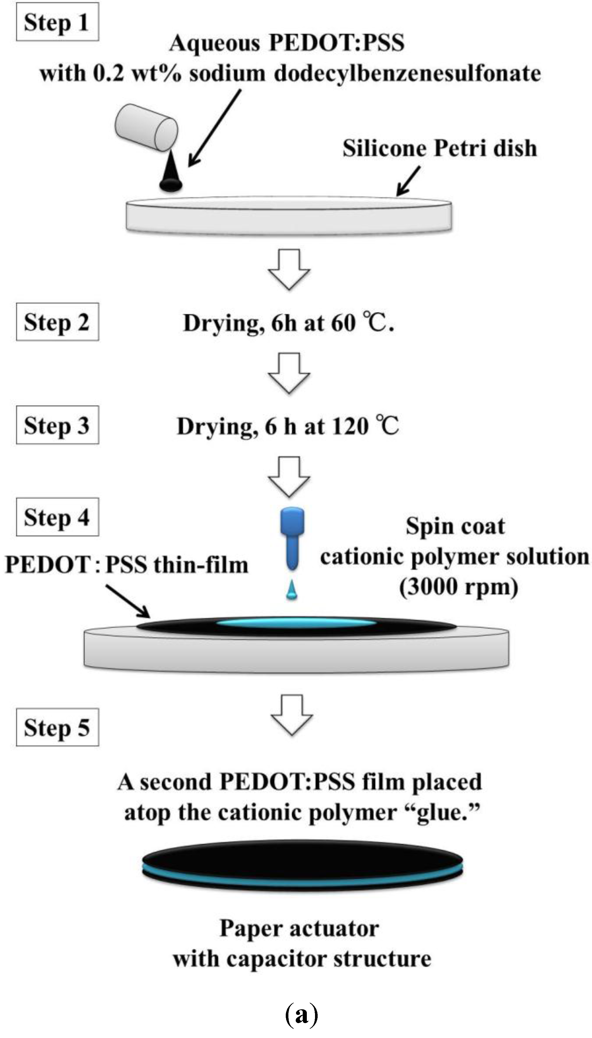
Figure 1 shows the fabrication process for our paper actuator. In Step 1, a PEDOT/PSS solution including dodecylbenzenesulfonate acid sodium salt (0.2 wt%) was cast in a silicone Petri dish. The surfactant was introduced to improve the wetting properties of the solution on the Petri dish. The coating was dried at 60 °C for 6 h and 120 °C for 6 h.
The cationic polymer solution was prepared from 3-(methacrylamido)propyl trimethylammonium chloride (MAPTAC, 80 g) and 2,2'-azobis(2-methylbutyronitrile) (V-59, 0.7 g) as an initiator in ethanol (320 g) for a total monomer concentration of 20 wt%. The polymerization was carried out at 83 °C for 5 h while purging with dry nitrogen gas. The cationic MAPTAC ethanol solution was evaporated, and the MAPTAC was diluted with water to approximately 50 wt%.
In Step 4 in Figure 1, the aqueous cationic polymer solution was cast on the PEDOT:PSS thin film using a spin coater (3000 rpm, 1H-D7, Mikasa Co., Ltd., Tokyo, Japan). In the final step, another PEDOT:PSS film was used to sandwich the cationic polymer solution. The paper actuator was cut into 20 × 3 mm2 strip.
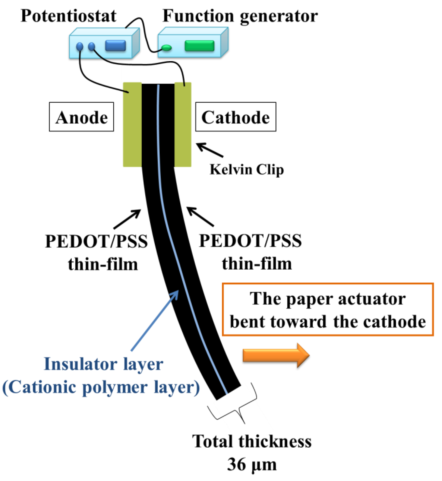
To apply the voltages, the actuator strip was clipped by a Kelvin clip that connected to the working and counter electrodes of a potentiostat (HAL-3001, Hokuto Denko Co. Ltd., Tokyo, Japan). The actuator strip was assessed by applying alternating square-wave voltages (±0.1, ±0.2, ±0.5, ±1, ±1.5, and ±3 V). The frequency of the square-wave voltage (1, 2, 5, and 10 Hz) was controlled by a function generator (HB-305, Co. Ltd., Tokyo, Japan).
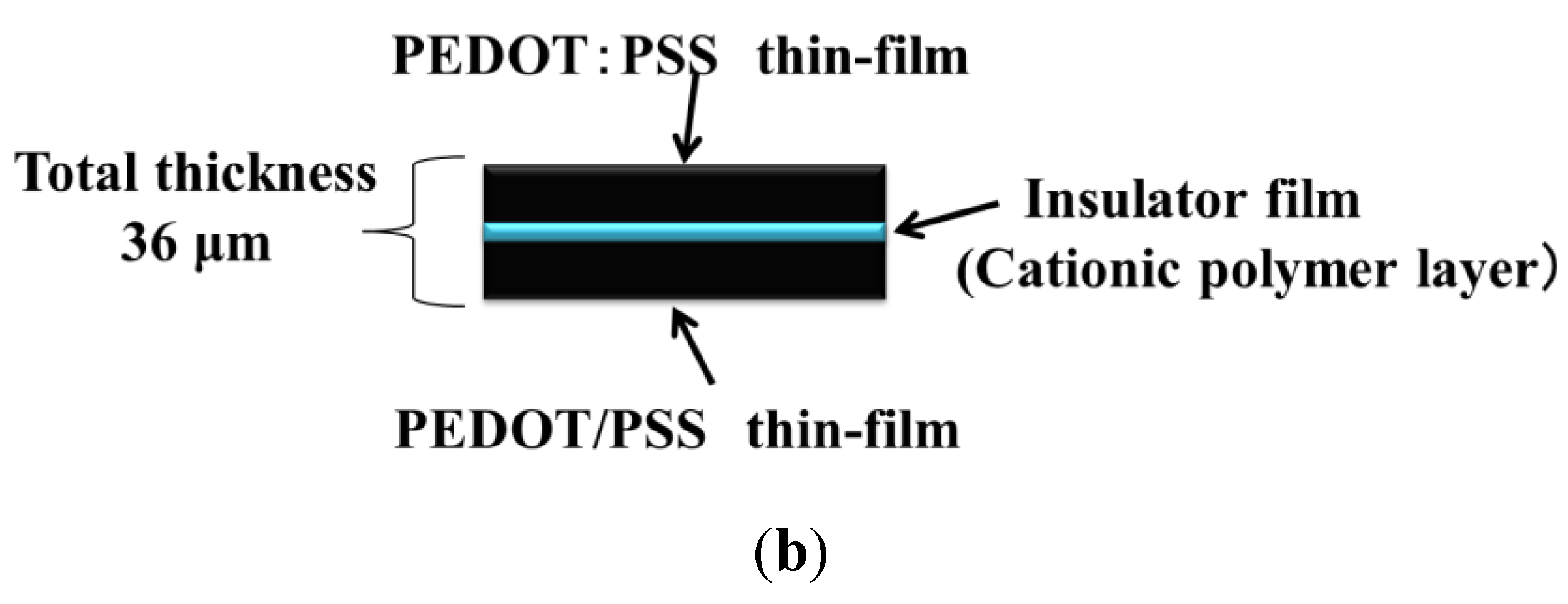
As shown in Figure 1b, the thickness of the paper actuator with the capacitor structure was approximately 36 μm. The PEDOT:PSS film was negatively charged because the PSS component of the conductive film bears sodium sulfonate groups. The two PEDOT:PSS electrodes were glued by the cationic MAPTAC polymer layer, with the adhesive strength originating from electrostatic interactions [15].
Figure 1.
(a) Process for the fabrication of the paper actuator with a capacitor structure, using only aqueous solutions. (b) Schematic illustration of the structure of the paper actuator.
Figure 1.
(a) Process for the fabrication of the paper actuator with a capacitor structure, using only aqueous solutions. (b) Schematic illustration of the structure of the paper actuator.


3. Results and Discussion
Before the paper actuator was assessed, it was soaked in water and the excess water was wiped away. Given the ionic nature of the EAP, water is indispensable for driving it because a solvent is needed to move the chloride ions in the insulation layer. Figure 2 shows the direction of the paper actuator movement under an applied voltage. The paper actuator bent toward the cathode. When the voltage was applied and the PEDOT:PSS electrode was charged, the chloride ions in the insulator film moved toward the anode. As they moved, the water content in the anode side increased. When the anode side swelled, owing to the movement of water and anions, the paper actuator bent to the cathode side. This driving mechanism is the same as found in well-characterized ionic EAPs, such as the IPMC [9].
Figure 2.
Schematic illustration of the motion of the paper actuator.

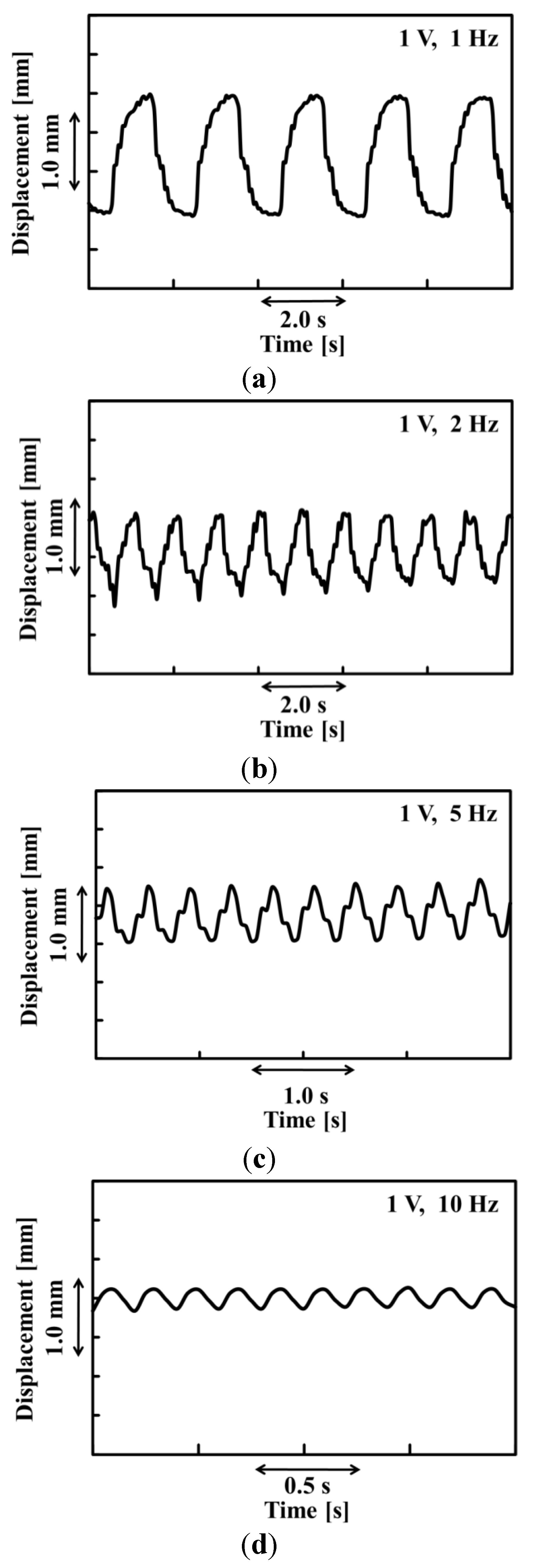
As the alternating square-wave voltages were applied to the paper actuator, it swung from side to side, synchronized with the change in the direction of the voltage. Figure 3a–d shows the time dependence of the displacement of the paper actuator. As shown in Figures, the displacement of the paper actuator decreased with an increase in the frequency. The displacement of the paper actuator was influenced by the deviation of the water content in the anode and cathode sides. We considered that the displacement of the paper actuator was affected by the frequency because the change of the water content in the electrode takes time. As shown in Figure 3, the waveform of the paper actuator exhibited nearly bilateral symmetry under all measurement conditions.
Figure 3.
Time dependence of the displacement of the PEDOT/PSS paper actuator at 1 V applied voltage and a frequency of (a) 1, (b) 2, (c) 5, and (d) 10 Hz.
Figure 3.
Time dependence of the displacement of the PEDOT/PSS paper actuator at 1 V applied voltage and a frequency of (a) 1, (b) 2, (c) 5, and (d) 10 Hz.

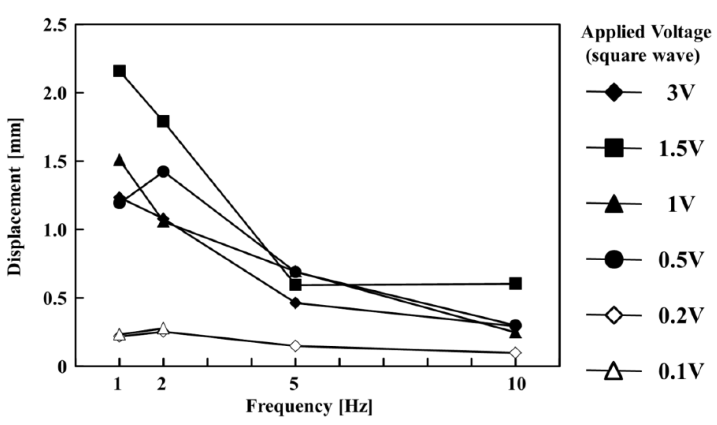
Figure 4 shows the relationship between the displacement of the paper actuator and the frequency of the alternating square-wave voltage. In the case of 1 Hz at 1.5 V, the maximum displacement was 2.2 mm. When the applied voltages were 0.1 and 0.2 V, the displacement dramatically decreased at all frequencies. When the applied voltage was 0.1 V, the actuator did not drive in 5 and 10 Hz. The applied voltage affected the charging rate in the PEDOT:PSS film. The degree of the charge deviation affected the concentration differential of the chloride ion on the anode side. The water content in the anode side was influenced by the concentration of the chloride ion because the osmotic pressure difference is determined by the concentration differential of the ion. Therefore, low voltage conditions (0.1 and 0.2 V) resulted in the decreased displacement of the paper actuator. In addition, when the applied voltage was 3 V, the displacement of the paper actuator was smaller than at 1.5 V at all frequencies. When 3 V was applied to the paper actuator, the Joule heating was higher than at lower applied-voltage conditions. The generated Joule heat at 3 V promoted the evaporation of the water, and the motion of the paper actuator was affected.
Figure 4.
Relationship between frequency and displacement of the paper actuator at different applied voltages (0.1, 0.2, 0.5, 1, 1.5, and 3 V).
Figure 4.
Relationship between frequency and displacement of the paper actuator at different applied voltages (0.1, 0.2, 0.5, 1, 1.5, and 3 V).

4. Conclusions
A novel 36-μm-thick paper actuator was constructed and its motion and displacement under applied voltages were assessed. The paper actuator bent to the cathode side when a voltage was applied because chloride ions in the insulator film and the water around them flowed to the anode side. The motion of the paper actuator exhibited bilateral symmetry, and the maximum displacement was 2.2 mm at 1.5 V.
Acknowledgments
This work was carried out under the auspices of the TEPCO Memorial Foundation. We also received support through a grant for Scientific Research in an Innovative Area, “Molecular Robotics” (24104003), from the Ministry of Education, Culture, Sports, Science, and Technology, Japan (MEXT).
Author Contributions
Yusuke Hara designed the research, and conducted experiments. Yusuke Hara and Yoshinori Yamaguchi analyzed data, and wrote the article.
Conflicts of Interest
The authors declare no conflict of interest.
References
- Bar-Cohen, Y. Electroactive Polymer (EAP) Actuators as Artificial Muscles: Reality, Potential, and Challenges, 2nd ed.; SPIE Press: Cardiff, UK, 2004. [Google Scholar]
- Jager, E.W.H.; Smela, E.; Ingana, O. Microfabricating conjugated polymer actuators. Science 2000, 290, 1540–1545. [Google Scholar] [CrossRef]
- Smela, E.; Inganas, O.; Lundstrom, I. Controlled folding of micrometer-size structures. Science 1995, 268, 1735–1738. [Google Scholar] [CrossRef]
- Smela, E. Conjugated polymer actuators for biomedical applications. Adv. Mater. 2003, 15, 481–494. [Google Scholar] [CrossRef]
- Shahinpoor, M.; Bar-Cohen, Y.; Simpson, J.O.; Smith, J. Ionic polymer-metal composites (IPMCs) as biomimetic sensors, actuators and artificial muscles—A review. Smart Mater. Struct. 1998. [Google Scholar] [CrossRef]
- Baughman, R.H. Conducting polymer artificial muscles. Synth. Met. 1996, 78, 339–353. [Google Scholar] [CrossRef]
- Pelrine, R.E.; Kornbluh, R.D.; Joseph, J.P. Electrostriction of polymer dielectrics with compliant electrodes as a means of actuation. Sens. Actuators A Phys. 1998, 64, 77–85. [Google Scholar] [CrossRef]
- Pelrine, R.E.; Kornbluh, R.D.; Pei, Q.; Joseph, J. High-speed electrically actuated elastomers with strain greater than 100%. Science 2000, 287, 836–839. [Google Scholar] [CrossRef]
- Oguro, K.; Kawami, Y.; Takenaka, H. Bending of an ion-conducting polymer film-electrode composite by an electric stimulus at low voltage. J. Micromach. Soc. 1992, 5, 27–30. [Google Scholar]
- Fukushima, T.; Asaka, K.; Kosaka, A.; Aida, T. Fully Plastic Actuator through Layer-by-Layer Casting with Ionic-Liquid-Based Bucky Gel. Angew. Chem. Int. Ed. 2005, 44, 2410–2413. [Google Scholar] [CrossRef]
- Sasaki, M.; Lin, W.; Tamagawa, H.; Ito, S.; Kikuchi, K. Self-Sensing Control of Nafion-Based Ionic Polymer-Metal. Actuator 2013, 2, 74–85. [Google Scholar] [CrossRef]
- Nakabo, Y.; Mukai, T.; Asaka, K. Biomimetic Soft Robots Using IPMC. In Electroactive Polymers for Robotic Applications; Kim, K.J., Tadokoro, S., Eds.; Springer: London, UK, 2007; pp. 165–198. [Google Scholar]
- Asaka, K.; Oguro, K.; Nishimura, Y.; Mizuhata, M.; Takanaka, H. Bending of Polyelectrolyte Membrane–Platinum Composites by Electric Stimuli I. Response Characteristics to Various Waveforms. Polym. J. 1995, 27, 436–440. [Google Scholar]
- Asaka, K.; Fujiwara, N.; Oguro, K.; Onishi, K.; Sewa, S. State of Water and Ionic Conductivity of Solid Polymer. Electrolyte Membranes in Relation to Polymer Actuators. J. Electroanal. Chem. 2001, 505, 24–32. [Google Scholar]
- Abe, H.; Hara, Y.; Maeda, S.; Hashimoto, S. Surface modification method for adhesion of gels. Chem. Lett. 2014, 43, 243–245. [Google Scholar] [CrossRef]
© 2014 by the authors; licensee MDPI, Basel, Switzerland. This article is an open access article distributed under the terms and conditions of the Creative Commons Attribution license (http://creativecommons.org/licenses/by/4.0/).
Share and Cite
MDPI and ACS Style
Hara, Y.; Yamaguchi, Y. Development of a Paper Actuator with PEDOT:PSS Thin-Films as An Electrode. Actuators 2014, 3, 285-292. https://doi.org/10.3390/act3040285
AMA Style
Hara Y, Yamaguchi Y. Development of a Paper Actuator with PEDOT:PSS Thin-Films as An Electrode. Actuators. 2014; 3(4):285-292. https://doi.org/10.3390/act3040285
Chicago/Turabian StyleHara, Yusuke, and Yoshinori Yamaguchi. 2014. "Development of a Paper Actuator with PEDOT:PSS Thin-Films as An Electrode" Actuators 3, no. 4: 285-292. https://doi.org/10.3390/act3040285