Article

Force-Sensing Actuator with a Compliant Flexure-Type Joint for a Robotic Manipulator

1
CEA, LIST, Interactive Robotics Laboratory, Gif-sur-Yvette F-91191, France
2
ARAID-EU, Centro Universitario de la Defensa, Ctra. de Huesca s/n, 50090 Zaragoza, Spain
3
LIAS-ENSIP, University of Poitiers, 86073 Poitiers, France
*
Author to whom correspondence should be addressed.
Actuators 2015, 4(4), 281-300; https://doi.org/10.3390/act4040281
Submission received: 28 August 2015 / Revised: 13 November 2015 / Accepted: 23 November 2015 / Published: 3 December 2015
(This article belongs to the Special Issue High-Resolution Actuators)

Abstract

:
This paper deals with the mechatronic design of a novel self-sensing motor-to-joint transmission to be used for the actuation of robotic dexterous manipulators. Backdrivability, mechanical simplicity and efficient flexure joint structures are key concepts that have guided the mechanical design rationale to provide the actuator with force sensing capabilities. Indeed, a self-sensing characteristic is achieved by the specific design of high-resolution cable-driven actuators based on a DC motor, a ball-screw and a monolithic compliant anti-rotation system together with a novel flexure pivot providing a frictionless mechanical structure. That novel compliant pivot with a large angular range and a small center shift has been conceived of to provide the inter-phalangeal rotational degree of freedom of the fingers’ joints to be used for integration in a multi-fingered robotic gripper. Simultaneously, it helps to remove friction at the joint level of the mechanism. Experimental tests carried out on a prototype show an accurate matching between the model and the real behavior. Overall, this mechatronic design contributes to the improvement of the manipulation skills of robotic grippers, thanks to the combination of high performance mechanics, high sensitivity to external forces and compliance control capability.

1. Introduction

In mechatronics design, appropriate methods are necessary to meet specific demands required for versatile gripping and dexterous robotic manipulation tasks. These approaches have allowed the elaboration of complex robotic grippers that are capable of surpassing, in their adaptability to the task, the performances of the first gripper mechanism with one single degree of freedom. The dexterous manipulation function is indeed one of the most complex functions to perform with a robotic system [1]. These aspects have become the object of numerous research activities [2,3,4,5], and an increasing number of robotic hands have been developed for research and industry [6,7,8,9,10,11].
Among the drawbacks of present-day human-like hands are the complex kinematic structure, the high number of actuators and the sophistication of sensing systems [12]. Indeed, the preferred approach to transmit the motion to the joints from the actuators consists of using a mechanical transmission system that is generally composed of a combination of bodies, tendons, gears, springs and pulleys. Tendons have the advantage of weight and flexibility of use [13], but they can complicate the mechanism of a part, on the one hand, and reduce the bandwidth of a system, on the other hand. The complexity of the fingers’ design, and generally that of the dexterous manipulator kinematics, reveals unwanted phenomena that are able to degrade or disrupt the fine manipulation tasks. Performing dexterous manipulation tasks assumes, as a pre-requisite, the use of reliable and precise mechanical systems, which are capable of overcoming some limitations associated with unwanted nonlinear phenomena, such as friction. Thus, the study of the actuation dimensioning and the mechanical transmissions between the actuators and the joints remains crucial. The friction, hysteresis and limited bandwidth (due to finite rigid transmissions and springs) phenomena may interfere with the manipulation abilities of the system if they are not taken into account at the initial design stage of the system.
When multi-fingered grippers are designed to meet restricted and practical requirements, they can be fulfilled with a minimalistic design rationale for practical applications, i.e., using the least number of actuators, the simplest set of sensors, etc., for a given task [12]. Cost effectiveness and reliability are objectives to be pursued in such a system design and make an integrated and efficient architecture an optimal solution for most manipulation tasks. An optimal design of the mechanical transmission allows one to overcome some of the limitations mentioned above: the use of the elastic deformation of materials to design minimalist compliant joints that substitute traditional contact-based joints [14], as well as the choice of the actuation architecture and technology [15] play a key role in the system performances. The present paper reports practical and useful elements for the mechatronic design of a robotic motor-to-joint transmission dedicated to manipulation tasks.
A central pillar of our design approach is the use of backdrivable actuators, together with backlash-free and frictionless compliant structures. This brings forward several advantages:
  • High-performance mechanics improve the level of dexterity related to the mechanical structure; control-wise and minimum friction leads to an enhanced stability and fine manipulation capability [16].
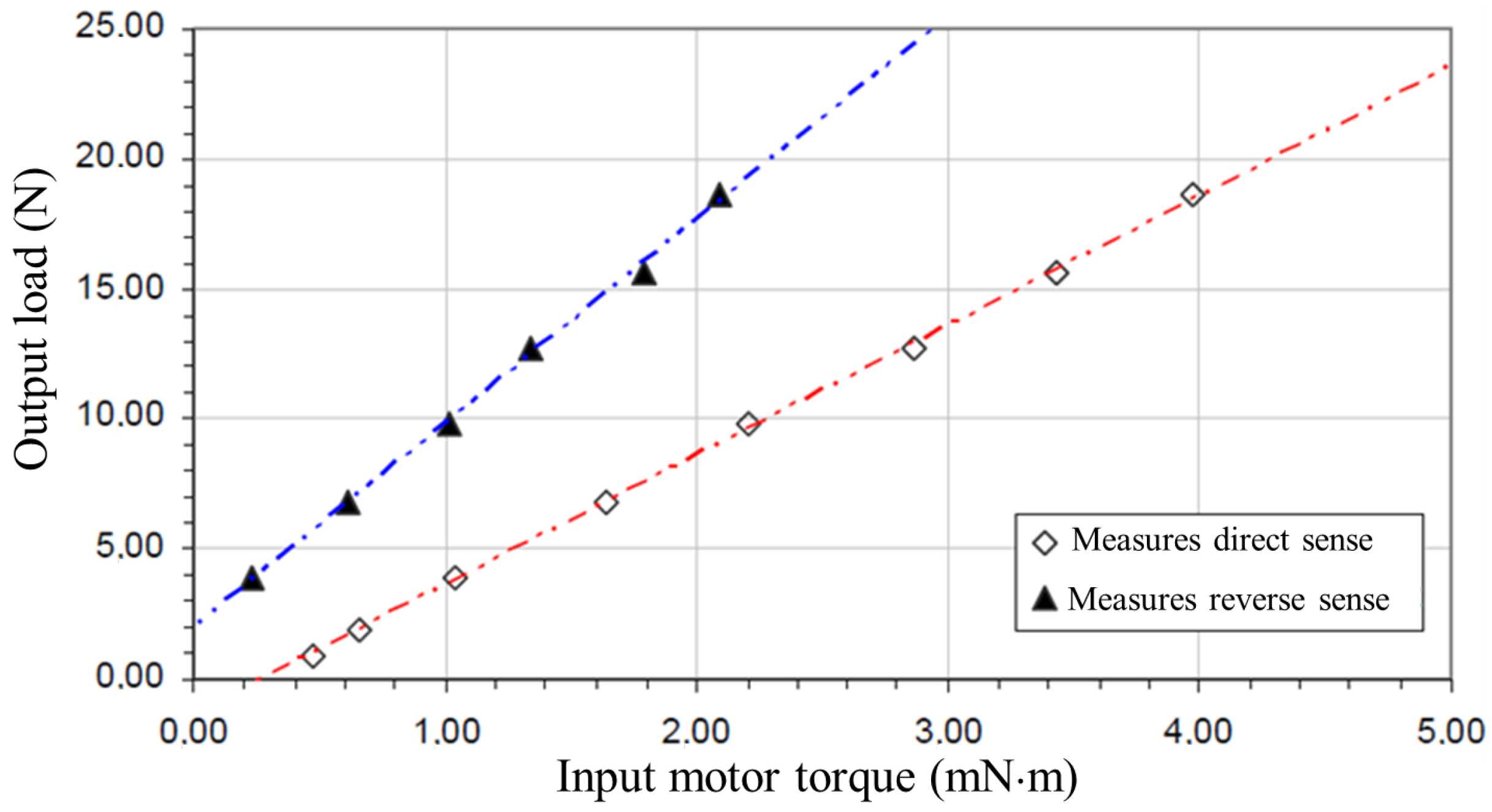
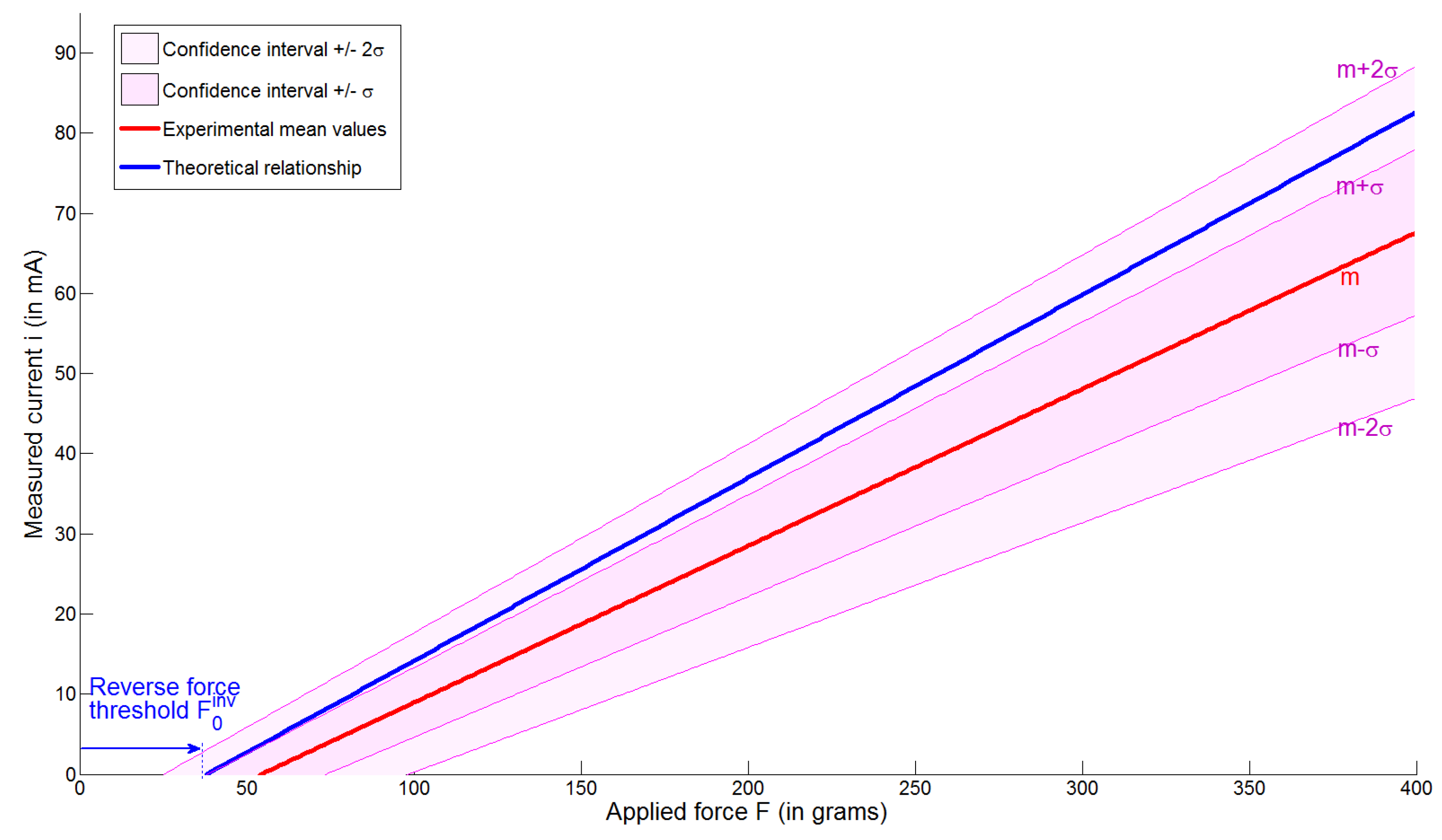
  • Joint torques are transmitted back as a resistive torque to the DC motor shaft, which can be measured by current sensing [17]. This permits one to estimate external forces exploiting the actuators as sensors, thus improving the dexterity related to the sensory apparatus.
  • The resulting mathematical model of the physical behavior of the finger enables alternative strategies to control the mechanical compliance of the finger.
  • As additional advantages of the self-sensing approach, the absence of force sensors means wiring simplification, avoidance of sensor drift and reduction of the number of components.
The two main components of the mechatronic design of our high-resolution actuator rely on a novel flexible pivot with large angular range and minimum axis drift to be implemented on the structure, together with an optimized linear actuator endowed with the self-sensing capability. To reach a high level of resolution, this work firstly focuses on the design of a joint, with the intent of replacing commonly-used contact-based joints with flexure-based joints [18]. This approach allows one to remove friction and wear, as the motion of joint actuation is obtained by means of flexures actuated with tendon-driven transmission. However, large displacements and small center shift are antagonistic requirements in terms of design objectives. In this context, a novel flexible pivot with a large angular range (90 ) and small center shift (<0.08 mm) has been conceived. Then, an optimized backdrivable actuator based on a DC motor, a ball-screw and a frictionless, backlash free anti-rotation system permits one to estimate contacts with the object directly at the actuator level, thus avoiding complicated sensing systems [19]. At the end, the specifically-developed architecture along with its mathematical model show that the proposed solution meets all design requirements for addressing dexterous and precise manipulation tasks with integrated and compact elements.
This paper is organized as follows: Firstly, the general design rationale and overview of the actuation unit is outlined. Secondly, the mechanical design of the motor-to-joint transmission is presented with a focus on the tendon-driven actuation principle and monolithic frictionless structure. Thirdly, the inter-phalangeal rotational joint is introduced and experimentally characterized. Then, the analytical model and self-sensing strategy are presented, and experimental tests on a prototype are discussed. Finally, conclusions and future lines of work are summarized.

2. Design Rationale

Improved grasp adaptability and protection against unexpected external impacts are important characteristics that bring robotic grippers closer to human hands. These features are particularly important for service robotics where the interaction with unknown environments is intended. Furthermore, when executing in-hand manipulation, a robotic hand should be able to accurately move and change the orientation of an object whilst maintaining a stable grasp. To perform such a complex manipulation task, the hand should not only be compliant, but also highly sensitive to external applied forces.
A highly backdrivable actuation system and frictionless flexible structure enable both a natural compliance and the self-sensing capability of the contact forces at the actuator level. Besides, this approach provides other additional advantages, such as wiring simplification, avoidance of sensors (and the associated sensor drift) and better controllability. To our knowledge, there are few existing anthropomorphic robotic hands that have used it so far, leaving room for improvement [11].
The actuation mechanism is composed of a DC mini-motor and an optimal miniaturized screw cable system actuator (Figure 1). More details on the motor-to-joint transmission will be given in the next sections. Forces generated by the actuation mechanism are transmitted to the finger by means of a force transmitting tendon; given that the actuation mechanism is mechanically backdrivable, forces applied to the tendon are directly translated as a resistive torque on the motor shaft. In turn, this torque can be estimated from the motor current sensing, and the contribution of the external forces applied to the finger can be calculated.
Figure 1. Finger prototype integrating the inter-phalangeal rotational pivot and the tendon-driven backdrivable transmission.
Actuators 04 00281 g001
In our present case, which considers only two tendons and a planar mechanism, the force-closure problem has been simplified to the computation, for each configuration of angular displacement of the joint driven by unidirectional actuating cables, of:
  • the set of directions along which a force applied to the finger can be balanced by the cables (working only under tensile strength and not compression);
  • plus, for each of those directions, the maximum value of external force that can be balanced taking into account the output of the actuators used to pull the cables.
The force-closure problem represents here a set of finger configurations where the cable tensions can balance an arbitrary external wrench applied on the fingertip, under the requirement of non-negative tension cable tensions, as well as maximum admissible tensions [20,21]. A computational optimization process of the geometric parameters of the transmission (pulleys’ radii and different topologies of the cable routing) has been carried out to maximize (i) the force output and (ii) the range of directions along which an external force applied to the fingertip can be balanced by positive tensions of the cables.
Regarding the mechanical efficiency of the actuation structure, the design approach of substituting commonly-used contact-based joints by compliant joints has been adopted. This removes friction and wear, as the motion of such joints is achieved by the elastic deformation of a solid material. The main drawbacks of compliant joints are their limited range of motion and the center drift (the axis of rotation moves as the piece deforms, affecting the kinematics). Indeed, according to gripper design specifications, a large angular range (90 ) is needed while maintaining a minimum and predictable center shift. In addition, from the standpoint of integration into a real prototype of the system assembly, the pivot must be compact in size (millimetric scale) and easy to manufacture. Even though different compliant pivots exist in the literature, none of them fulfill all of these requirements at the same time. The main reason for this is that large displacements and small center shift are antagonistic requirements in terms of design objectives. The proposed paper shows a new flexible pivot specifically designed to be implemented as the inter-phalangeal rotational joints of the fingers. A deeper insight will be given in Section 3.

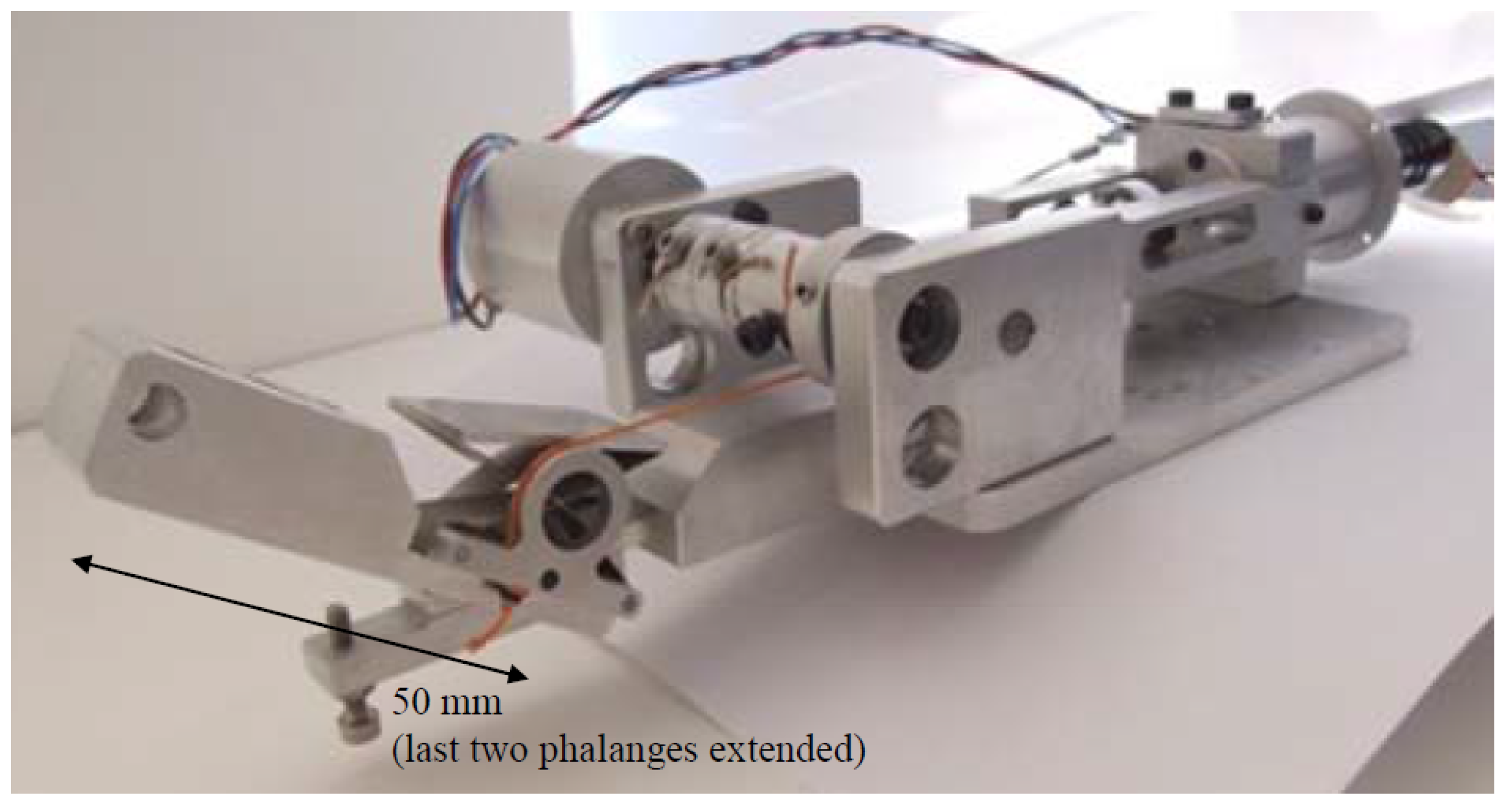
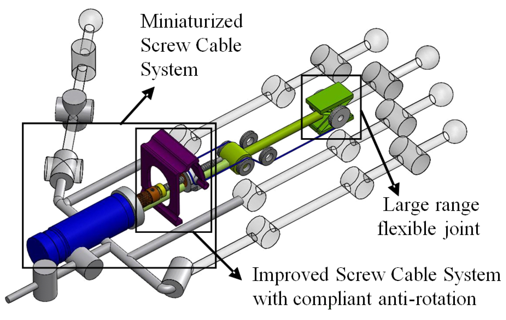
3. Motor-to-Joint Transmission

This section deals with the mechatronic design of the backdrivable motor-to-joint transmission. It can be divided into two parts: an optimized tendon-driven linear actuator and a frictionless anti-rotation system.

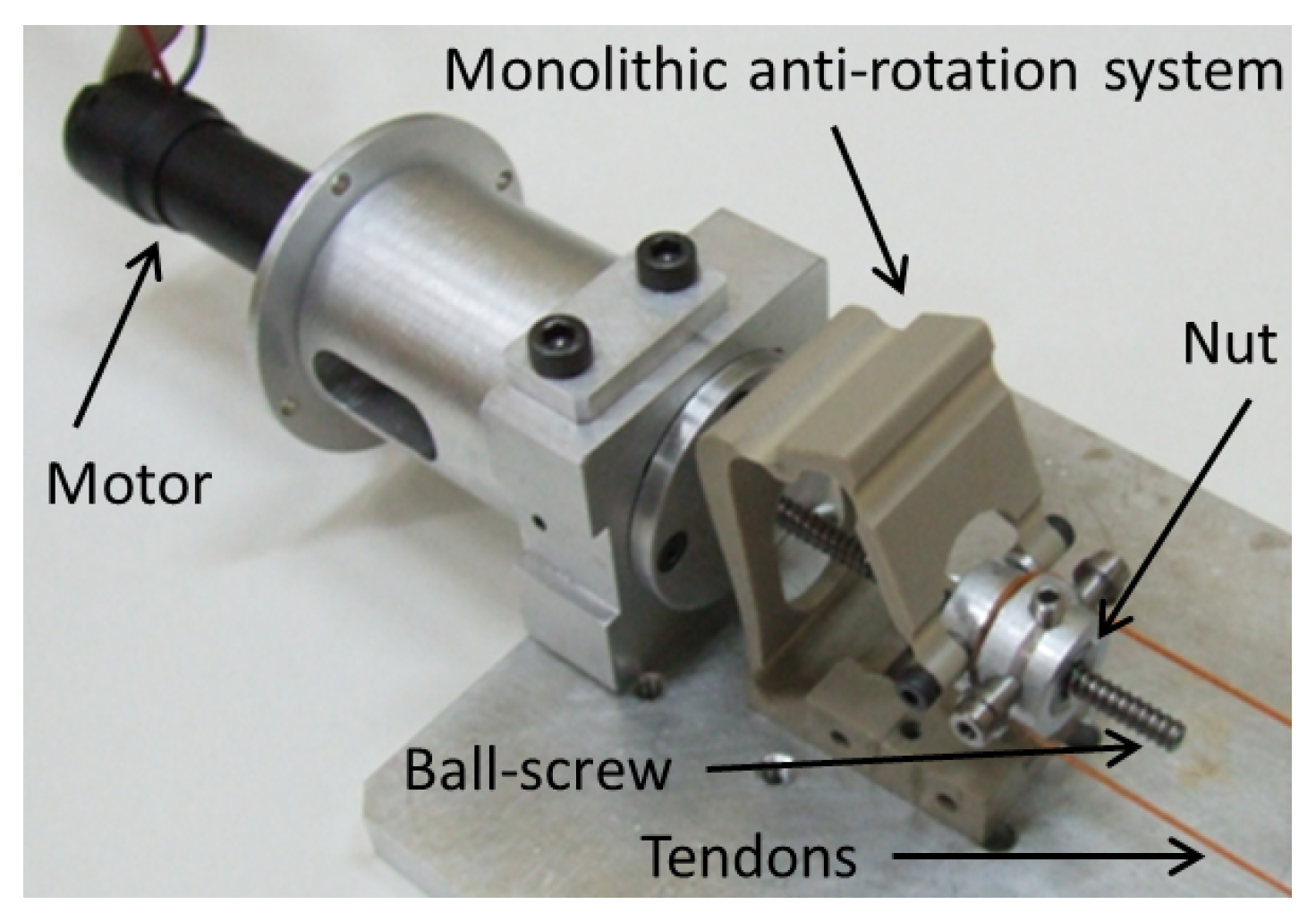
3.1. Tendon-Driven Actuation Principle

The operation can be briefly described as follows: Firstly, an electrical motor transmits a rotational movement to a ball-screw in which the nut has been locked in rotation, but left free to displace along its axis (by means of an anti-rotation mechanism) [19]. The induced displacement of the nut is then transmitted to a pair of cables, which finally drive a rotational joint. For high pitch-to-radius ratios, this actuator shows a good backdrivability. It also permits a single-acting actuation architecture with passive return [22], which greatly simplifies tendon routing and therefore reduces friction. Note that friction associated with force-transmitting tendons is by far the major source of friction in complex mechanical hands.
Friction-dependent backdrivability needs to be determined. For this purpose, experimental tests were performed on the Steinmeyer Type B (3 mm × 1 mm) ball-screw, which is the key element to the backdrivability of the actuators. Figure 2 shows experimental measures for both senses of transmission. The intersection with the horizontal axis gives the threshold of motor torque, which initiates the movement. This direct threshold is f 0 d i r = 0 . 273 mN·m. The intersection with the vertical axis gives the threshold of external load, which initiates the movement. This reverse threshold is f 0 i n v = 2 . 01 N. The low reverse threshold indicates that very small loads can be detected by current sensing in the motor. The high reverse efficiency indicates that the image of the load, seen from the motor, is not much perturbed by energy losses in the ball-screw transmission [23].
Figure 2. Experimental measures on the ball-screw backdrivability.
Actuators 04 00281 g002

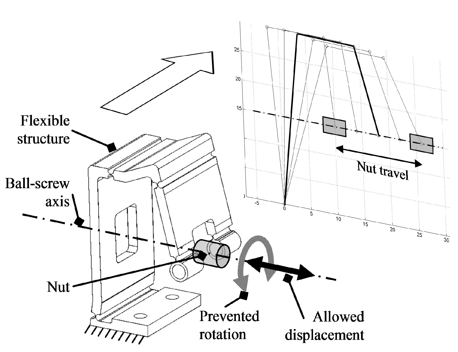
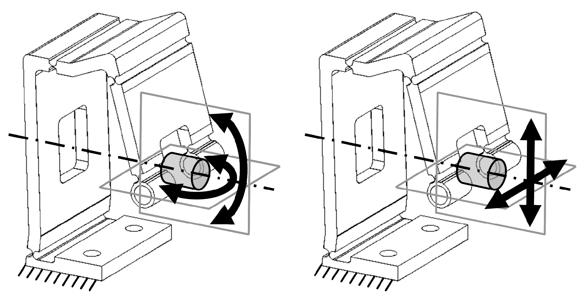
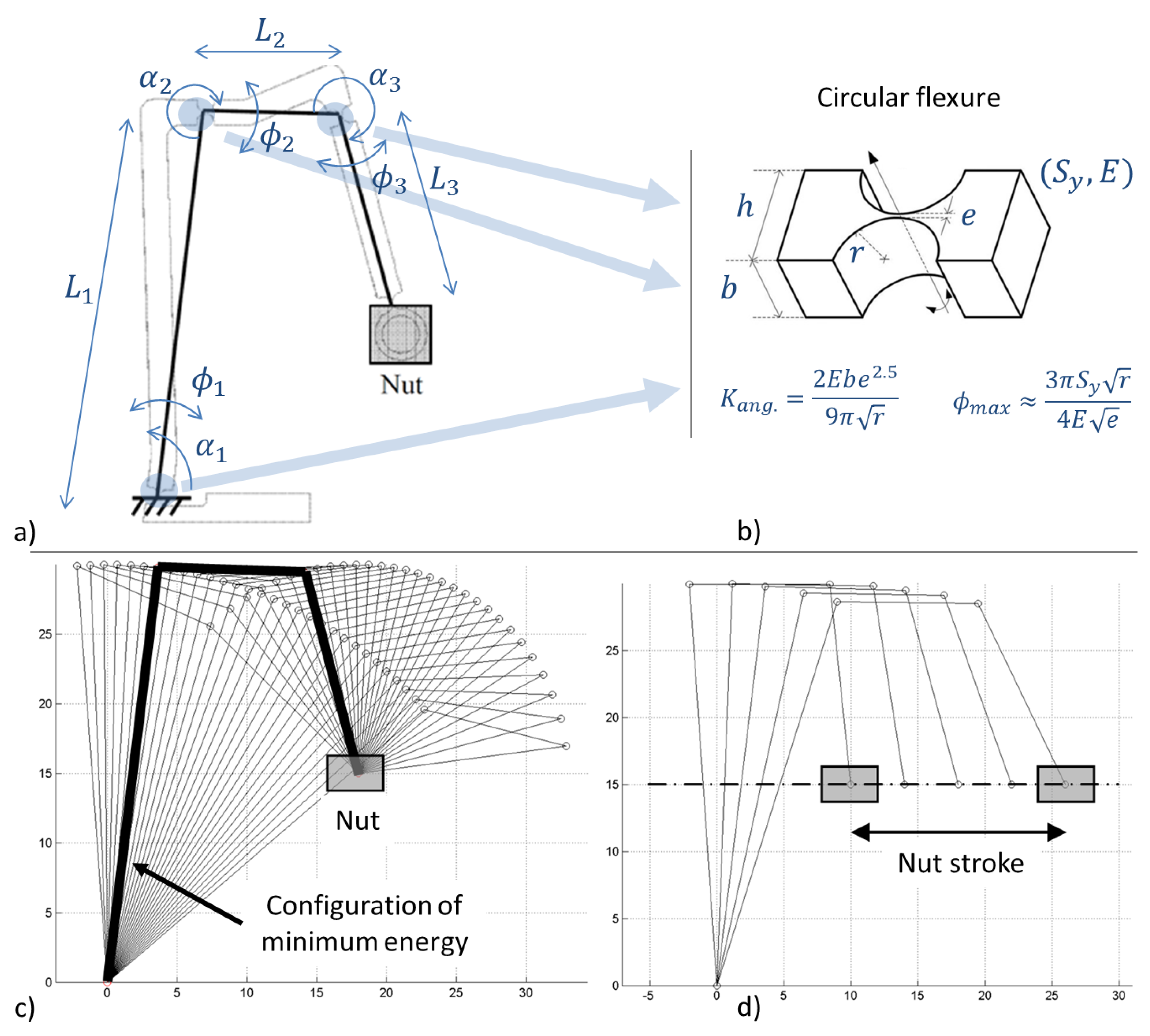
3.2. Monolithic Frictionless Anti-Rotation System

A flexible structure has been specifically designed to accomplish the anti-rotation function without introducing additional friction and backlash. As shown in Figure 3, it allows the linear displacement of the nut along the ball-screw axis by deformation of the flexible structure, while preventing the nut rotation around the ball-screw axis. As an additional advantage, the proposed anti-rotation system can be machined as a monolithic structure. This simplifies the assembly and minimizes the number of parts.
Figure 3. Monolithic frictionless anti-rotation system of the self-sensing linear actuator: prevented rotation and allowed displacement of the nut.
Actuators 04 00281 g003
Simultaneously, the anti-rotation device allows the nut to slightly displace and rotate along any transversal direction (Figure 4), which absorbs angular oscillations and avoids hyper-static constraints. Without this possibility, there would be a variable friction that would depend on the screw rotation angle and the nut travel. This would diminish the mechanical performance of the actuator and, therefore, the self-sensing characteristic.
Figure 4. Monolithic frictionless anti-rotation system of the self-sensing linear actuator: canceling of the effects caused by the angular oscillations and the hyper-static constraints.
Actuators 04 00281 g004
It is a protruded planar three-link serial mechanism, where each joint has been substituted by a compliant notch joint. The first link is connected to the ground, and the last link is attached to the nut. The shape of the structure is partially determined by the layout of the screw cable system components. Geometric parameters (i.e., relative orientation of the notch joints α i and link lengths L i for i = 1 , , 3 ) are optimized by the following procedure (Figure 5a):
  • For each position of the nut in the ball-screw axis, the theoretical configuration of minimum elastic energy of the structure is calculated (Figure 5c);
  • For the complete travel of the nut along the ball-screw axis, the previous step permits one to find the successive mechanism configurations, and the total angular displacement of each notch joint is calculated (Figure 5d);
  • Parameter values ( α i and L i for i = 1 , , 3 ) minimizing the largest angular displacement among the three joints ( m i n ϕ 1 m a x , ϕ 2 m a x , ϕ 3 m a x ) are chosen;
  • Once the angular displacements in the articulations are minimized and known, the parameters of the notch joint (Figure 5b) and the material selection (through its Young’s modulus E and its yield strength S y ) are specified, taking into account practical criteria regarding the integration of the actuator in a minimum package.
Figure 5. Basic principle of the compliant anti-rotation mechanism: (a) kinematics of the flexure-based three-bar linkage and its design parameters for optimization; (b) elementary circular flexure hinge joint; (c) configuration of minimum energy for a position of the nut; (d) successive mechanism configurations for the travel of the nut.
Actuators 04 00281 g005
In addition, the width of the structure plays an important role on the rotational stiffness of the anti-rotation system about the ball-screw axis. More precisely, the geometrical parameter of the notch joint width has been chosen as an optimal value of 20 mm. Width parameter b (see Figure 5b) is set to its maximum value in order to minimize the deformation of the mechanism when counteracting the torque transmitted by the nut. The mechanism has been studied using FEM software to simulate the loads that will result from the anti-rotation function. This analysis shows the maximum deformation of the structure is equivalent to a ± 0 . 1 rotation around the nut axis.
To sum up, the resulting compliant anti-rotation system has been optimized to provide a linear stroke of 16 mm and is able to absorb the maximum torque of the motor undergoing an equivalent elastic deformation of ± 0 . 1 . It has been machined in PEEK (Polyether ether ketone) polymer as a monolithic structure, because of its good S y / E ratio ( S y = 96 . 5 MPa, E = 3 . 6 GPa) and its excellent machinability. Figure 6 shows a prototype of the self-sensing linear actuator. The performance of the actuator, equipped with the anti-rotation device, the commercial ball-screw Steinmeyer Type B previously exposed and a commercial DC motor Maxon RE 16 coupled to a commercial encoder Maxon MR Type M are as follows: axial force of 29 . 86 N, no load max. linear velocity of 0 . 042 m/s and a linear position resolution of 0.002 mm.
Figure 6. Partial view of the prototype, including its monolithic anti-rotation system.
Actuators 04 00281 g006

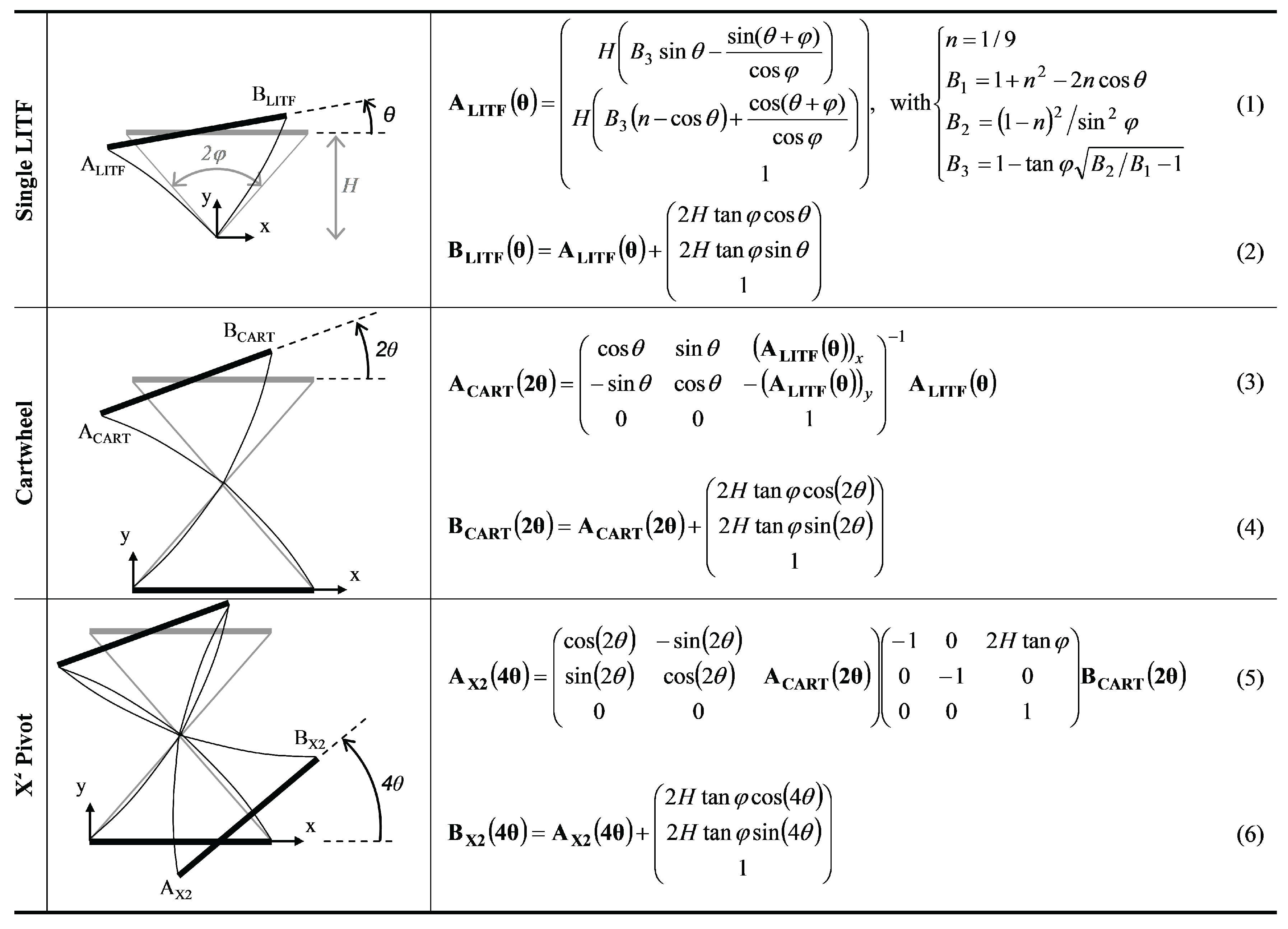
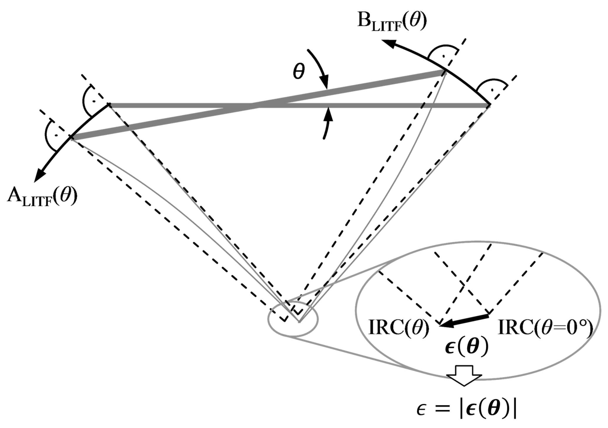
4. Inter-Phalangeal Rotational Joint
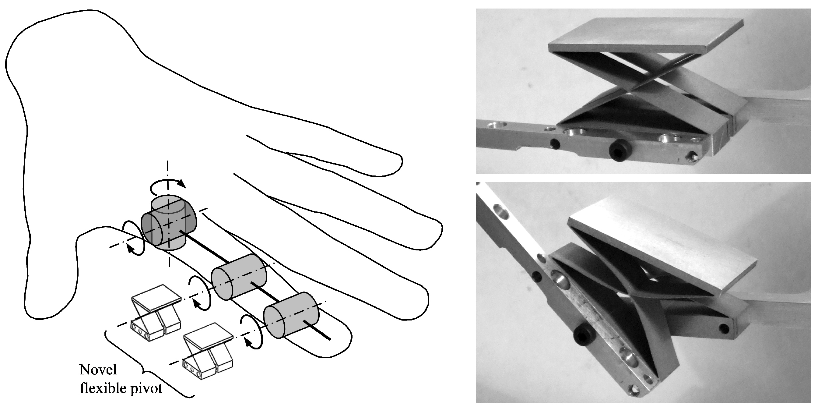
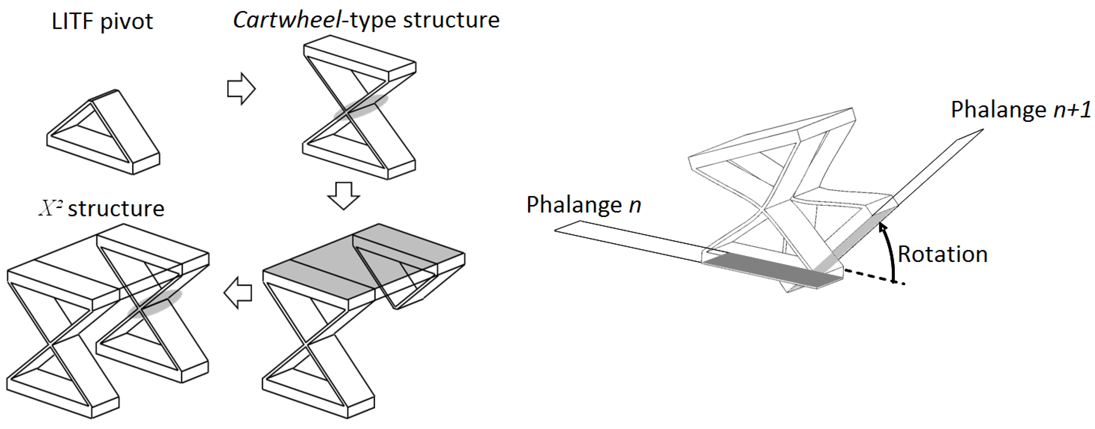
This section presents the analytical modeling of the novel pivot implemented as an inter-phalangeal rotational joint (Figure 7) and experimental tests on the first prototype.
Figure 7. On the left: flexible pivot X 2 as an interphalangeal pivot joint for the finger design with multiple degrees of freedom. On the right: monolithic structure prototype X 2 obtained by aluminum electrical discharge machining ( S y = 580 MPa, E = 73 GPa, 9 mm × 7 mm × 5 mm).
Actuators 04 00281 g007

4.1. Concept

The X 2 flexible pivot can be regarded as a simple cartwheel pivot, which is modified in a smart specific manner. In the first approach, such a modification consists on a cut, which sweeps the piece by a central plane perpendicular to the axis of rotation, affecting only the flexible leaves and one of the rigid volumes of the cartwheel (Figure 8). The new flexible pivot is then equivalent to two identical cartwheel pivots linked in series, which have their centers of rotation collocated.
Figure 8. Design and rotational motion produced by the X 2 pivot between two successive phalanges of a gripper finger.
Actuators 04 00281 g008

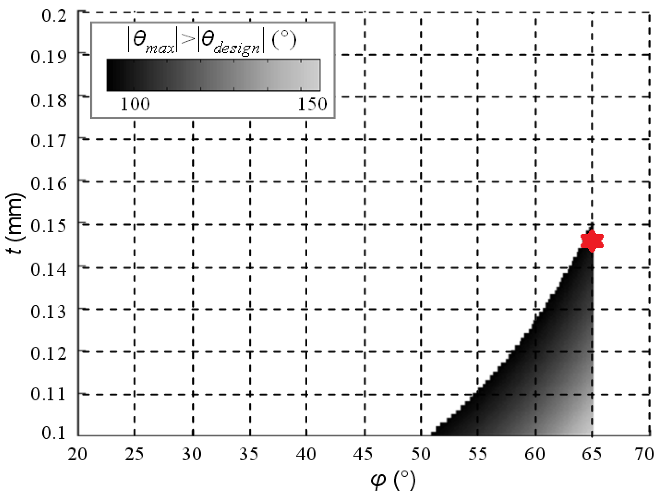
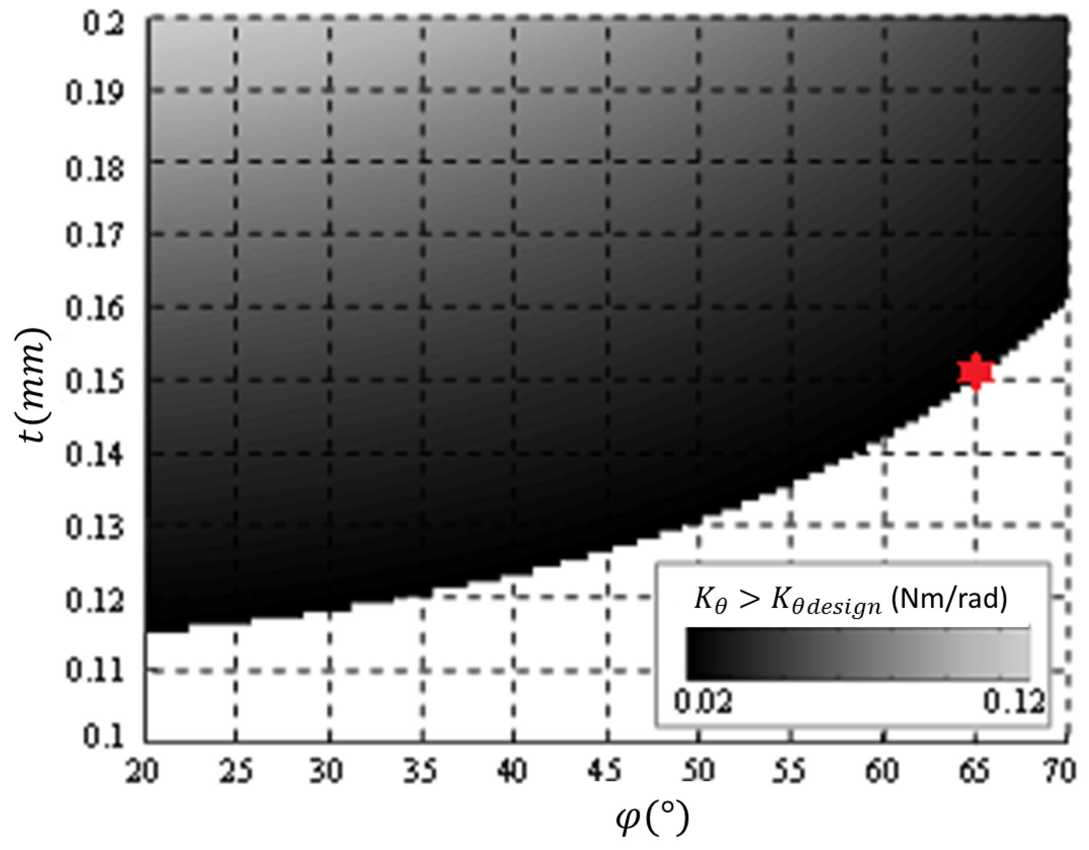
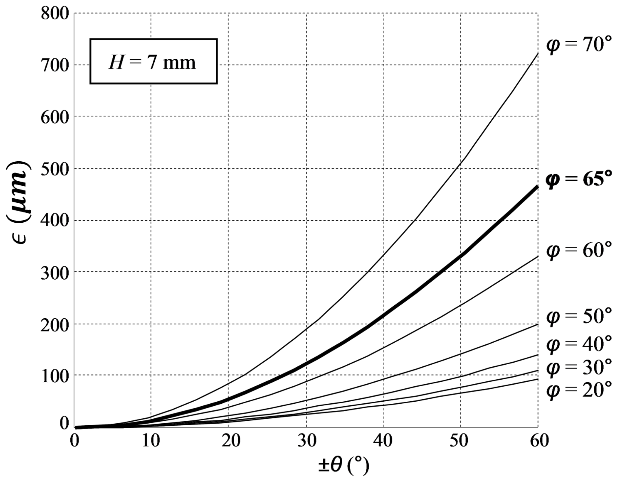
4.2. Design Optimization

The analytical modeling of the new pivot is based on the pseudo-rigid-body (PRB) model of the leaf-type isosceles-trapezoidal flexural (LITF) pivot, proposed by [24]. This model is especially interesting here, since a cartwheel is a particular serial connection of two LITF pivots, and consequently, the X 2 pivot is a specific serial connection of four LITF pivots. Equation (1) in Figure 9 is directly deduced from the results shown in [24], and then, Equation (2) is from geometrical reasoning. They represent the homogeneous coordinates of the trajectories of the vertices ( A L I T F , B L I T F ) of a single LITF pivot. Equations (1) and (2) can be used to establish the homogeneous transformation between the ground and a coordinate system attached to the moving rigid volume of the LITF. This, in turn, can be used to calculate the trajectories of the homologous vertices ( A C A R T , B C A R T ) of the cartwheel joint (Equations (3) and (4) in Figure 9). Likewise, Equations (3) and (4) permit one to establish the homogeneous transformation between the ground and a coordinate system attached to the moving rigid volume of the cartwheel. Analogously, this result permits one to calculate the trajectories of the vertices ( A X 2 , B X 2 ) of the X 2 pivot (Equations (5) and (6) in Figure 9). Figure 9 also shows the geometric parameters that take part in Equations (1) to (6): H is half the height of the X 2 pivot, and φ is half the angle between the two leaves that form the X 2 pivot.
Figure 9. Theoretical trajectories of the vertices for the leaf-type isosceles-trapezoidal flexural (LITF), cartwheel and X 2 pivots.
Actuators 04 00281 g009
Considering the X 2 pivot as the serial connection of two cartwheels and each cartwheel as a spring, the maximum deflection θ m a x is twice the maximum deflection of the cartwheel (given by [25]):
θ max = 2 H S y t cos φ E
where S y denotes the yield stress of the material, E is the Young modulus, t is the thickness of the leaves and φ is the half-angle between the leaves. It provides a practical design criterion: materials with a high S y / E ratio achieve larger values of the deflection θ max .
Following the same reasoning that led to the previous equation, the rotational stiffness value K θ of the X 2 pivot is half of the stiffness value of the cartwheel flexible pivot:
K θ = E w t 3 cos φ 6 H
where w is the width of the leaves that form the X 2 pivot.
Concerning the center shift ϵ, for an identical angular displacement of ± 10 , the value of ϵ of the X 2 joint is roughly 60-times smaller than the cartwheel one, regardless of the values of the geometric parameters. The center shift has been calculated as the distance between the instantaneous rotational center (IRC) calculated for θ = 0 and the IRC calculated for an angular displacement θ (Figure 10). Two main reasons explain the low parasitic center shift:
  • the two cartwheels that constitute the X 2 joint are arranged in a manner that makes their two respective center shift vectors ϵ ( θ ) compensate for one another;
  • for a flexible pivot, the value of ϵ increases rapidly with the angular displacement θ; therefore, as the overall displacement θ is distributed into smaller displacements over the two cartwheels, a large reduction of the center shift is achieved for each one.
Figure 10. Center shift ϵ calculated for a LITF joint.
Actuators 04 00281 g010
The flexible pivot has been designed to provide a large angular range of θ while maintaining a minimum center shift ϵ. Because of integration issues into the mechanical structure of the finger, the flexible pivot must fit into a section defined by H = 7 mm, w = 9 mm. For practical reasons regarding the electro-discharge machining process, the thickness of the leaves should not be smaller than t = 0 . 1 mm. Finally, due to the design of the finger actuation, the flexible pivot should display a rotational stiffness K θ 0 . 02 Nm/rad.
Equation (7) can then be used to find the set of feasible pairs ( φ , t ) that satisfy the design goal θ m a x θ d e s i g n , where θ d e s i g n has been chosen as 100 considering a safety factor less than two (Figure 11). Likewise, Equation (8) can be used to find the set of feasible pairs ( φ , t ) that satisfy the design goal K θ m a x K θ d e s i g n = 0 . 02 Nm/rad (Figure 12). The intersection of the two sets of feasible pairs ( φ , t ) shown in Figure 11 and Figure 12 is a set of geometries, which are solutions to the design problem, as they simultaneously satisfy the two constraints. In this case, there are a few solutions around (φ = 65 , t = 0.15 mm). Figure 13 provides a complete overview of the value of ϵ θ for different design values of φ. It can be observed that ϵ increases rapidly with φ; therefore, φ should be as small as possible to keep ϵ to a minimum. This is an important design criterion if multiple solutions appear as the intersection of the two sets of feasible pairs ( φ , t ) shown in Figure 11 and Figure 12. Table 1 resumes the obtained values of the geometry and performance parameters for the designed pivot, denoted with a red asterisk on Figure 11 and Figure 12.
Table 1. Final values of the X 2 pivot.
GeometryPerformances
H7 mm θ m a x ± 60
φ 65 ϵ ( θ = ± 10 ) 14 μ m
t0.15 mm ϵ ( θ m a x ) 467 μ m
w9 mm K θ 0.02 Nm/rad
Figure 11. Set of pairs φ , t satisfying the objective θ max θ d e s i g n = 100 (aluminum material, dimensions H = 7 mm, w = 9 mm).
Actuators 04 00281 g011
Figure 12. Set of pairs φ , t satisfying the objective K θ K θ d e s i g n = 0 . 02 Nm/rad (aluminum material, dimensions H = 7 mm, w = 9 mm).
Actuators 04 00281 g012
Figure 13. Center shift ϵ ( θ ) for different design values of φ.
Actuators 04 00281 g013

4.3. Experimental Performances

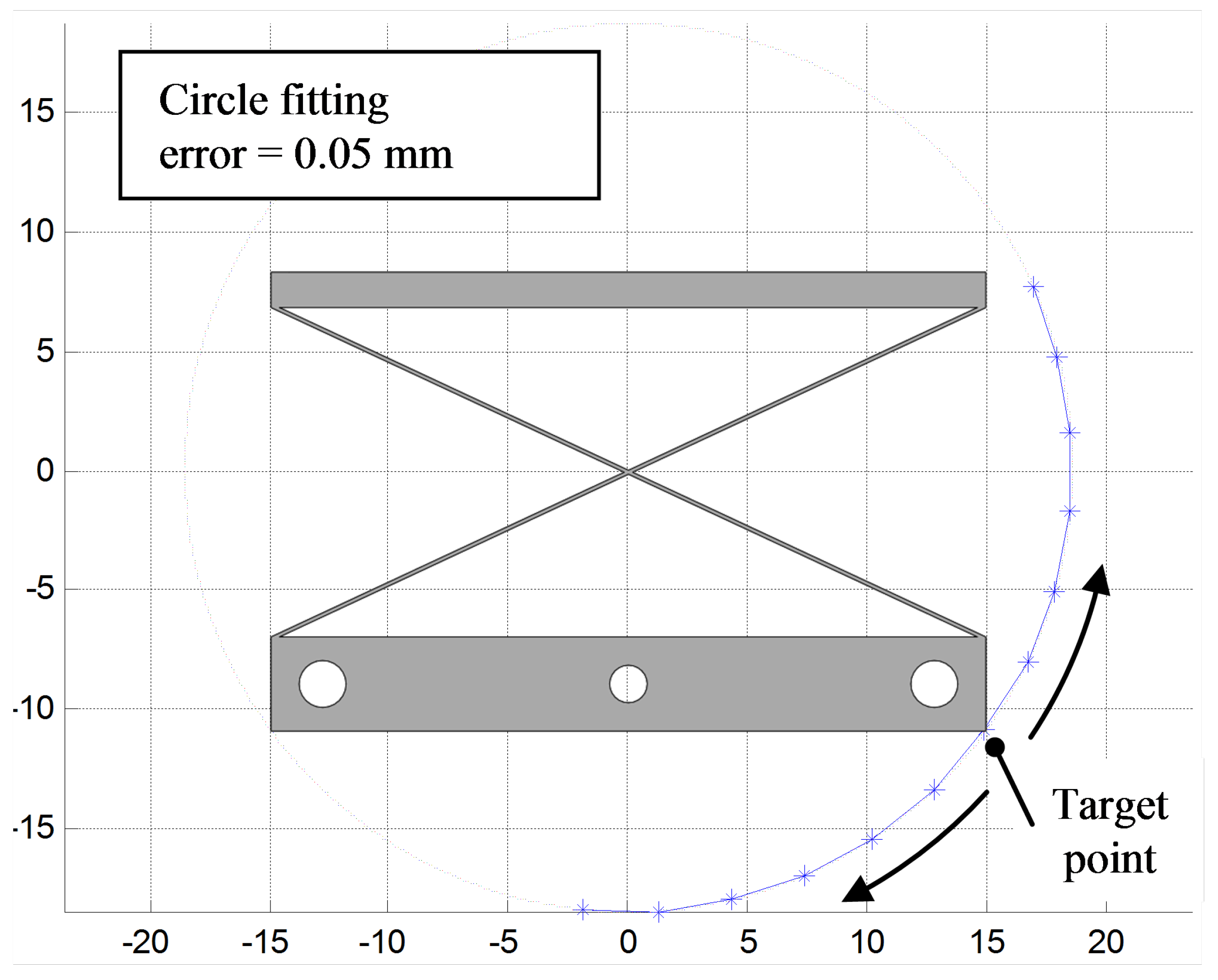
4.3.1. Accuracy of Motion

This test attempts to measure the accuracy with which the trajectory described by one point on the pivot fits a perfect circle. With zero parasitic center shift, such a trajectory should exactly fit the circle. In any other case, there is a fitting error between the trajectory and the circle, which increases with the center shift. The tests were carried out on the pivot isolated from the rest of the actuation unit. The trajectory of one target point has been measured using a profile projector (projection lens 10 × , resolution 0 . 01 mm). One end of the pivot was fixed on the ground, and the other end was moved to several reference angular displacements regularly spaced along the stroke using an extending cantilever acting as a phalanx. At each angular displacement, the ( x , y ) coordinates of the target point were measured and registered. Then, a circle was fitted to the collected data points. The fitting error is calculated as the maximum distance, measured along the radial direction, between any of the collected data points and the fitted circle.
From Figure 14, it can be seen that there is a good fit between the observed trajectory and a perfect circle, since the maximum absolute error norm is about 50 μm.
Figure 14. Observed trajectory of a target point on the tested X 2 pivot and circle fitted to the collected data points.
Actuators 04 00281 g014

4.3.2. Identification of Pivot Stiffness

Experimental tests have been performed to measure the rotational stiffness of the pivot. One end of the X 2 was fixed on the ground, while the other end was loaded with different known torques, using an extending cantilever acting as a phalanx. To produce the torque, a known force was applied in a direction perpendicular to both the cantilever and the pivot axis. The force was increased in order to increase the angle of rotation by steps of 10 degrees. As the pivot was isolated from the rest of the actuators, thus no lateral forces were applied on it. For each equilibrium state where applied torque was balanced by the stiffness of the pivot, the angular displacement was measured. The collected data along with the linear least squares fitting exhibit an experimental angular stiffness of the pivot, seen as the slope of the fitted curve, equal to K θ , e x p = 0 . 022 Nm/rad (Figure 15). This value matches the one predicted by Equation (8) for the geometry and material properties of the tested pivot, K θ = 0 . 022 Nm/rad. In addition, it puts forward a good linearity of the stiffness characteristic of the pivot, as well as an accurate model of its stiffness, which is a key factor for the success of any model-based control algorithm.
Figure 15. Experimental stiffness K θ , e x p of the tested X 2 pivot.
Actuators 04 00281 g015

5. Modeling and Self-Sensing Strategy

The mechatronic model of the self-sensing actuated joint and the strategy adopted to estimate external forces from the measured motor current are investigated in this section.

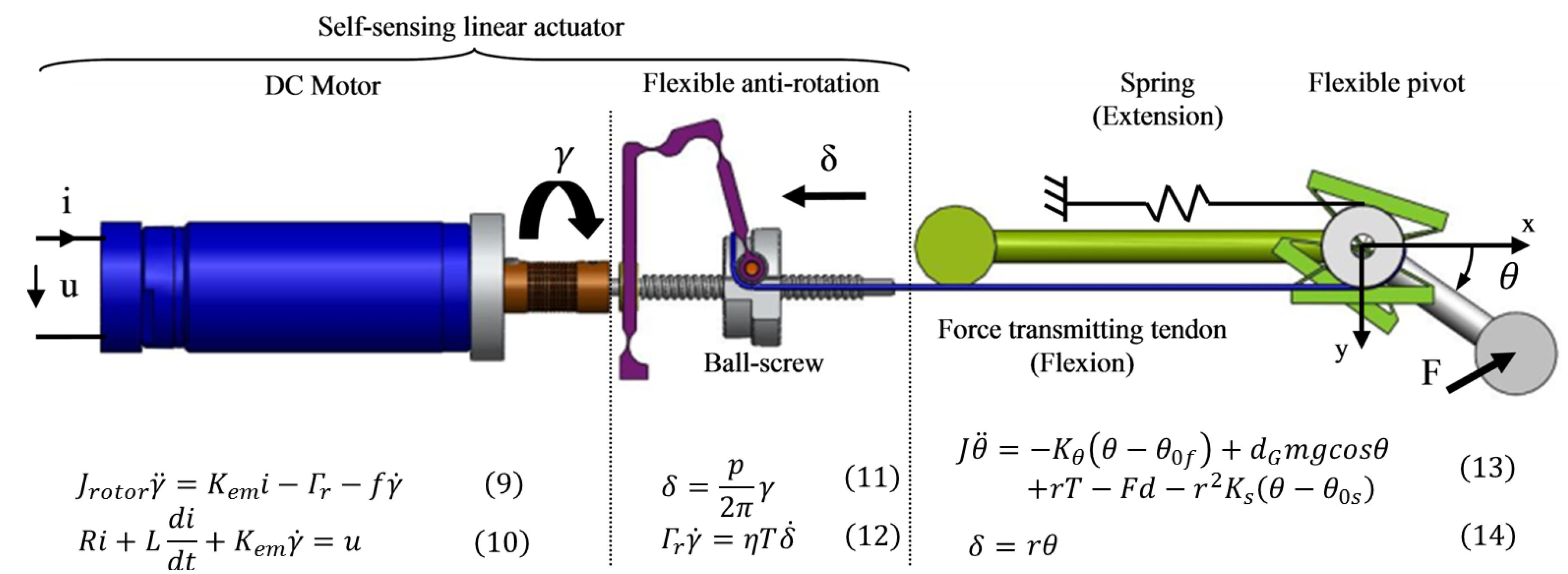
5.1. Modeling of the Tendon-Based Actuation Principle

The proposed system and its associated non-linear dynamic model are depicted in the equations provided in Figure 16. A brief description of the parameters used in these equations can be found in Table 2. On the left-hand side of Figure 16 is shown the actuation mechanism composed of a DC motor and the miniaturized screw cable system actuator, as described in Section 3. On the right-hand side is the representation of a simplified finger composed of the new pivot described in Section 4 and one rigid phalanx. Forces generated by the actuation mechanism are transmitted to the finger by means of a force-transmitting tendon to produce the flexion movement. Antagonist motion is driven by a spring. Based on experimental observations, the following assumptions have been considered in the model: the motor shaft rotation γ is directly transmitted to the ball-screw, and the whole joint is modeled by a rotational stiffness K θ , as checked previously. In addition, the model is simplified by neglecting the stiffness of the flexible anti-rotation structure along the direction of the ball-screw axis and the axis drift in the flexible joint.
Figure 16. Mechatronic model of the self-sensing actuated joint, including the anti-rotation system and the X 2 pivot.
Actuators 04 00281 g016
Table 2. Description of the model parameters.
ParametersDescription
θ 0 f Joint angle for relaxed flexible pivot
θ 0 s Joint angle for relaxed extension spring
JInertia of flexible pivot and finger
mMass of flexible pivot and finger
gGravitational acceleration
rNormal distance between tendon and pivot center
d G Distance between the gravity center and pivot center
dDistance between the effort application (F) and pivot center
K θ Flexible pivot stiffness
K s Antagonist spring stiffness
pScrew pitch
ηBall-screw efficiency
RDC motor resistance
LDC motor inductance
K e m DC motor constant
J r o t o r DC motor inertia
fDC motor viscous friction

5.2. Self-Sensing of External Forces Applied to the Finger

Given that the actuation mechanism is mechanically backdrivable, external forces F applied at the fingertip are directly translated into a resistive torque Γ r on the motor shaft through the force-transmitting tendon. This torque, in turn, can be calculated from the motor current i. Since the behaviors of the spring and the flexible joint are known, their contributions to Γ r can be estimated, as well as the contribution of the phalanx inertia and weight. Then, by subtraction of these terms from Γ r , the contribution of the external forces F applied to the finger can be calculated. This calculation gives to the actuator the capability of self-sensing the external forces applied to the finger, and this is possible by virtue of the actuation mechanism backdrivability and the overall mechanical efficiency.
The relationship between the current reference and rotation at the motor shaft can be expressed as the function of the position K p o s and speed K s p e controller’s gains as follows i = K p o s K s p e γ r - γ - K s p e γ ˙ , where the superscript * r stands for the reference value. That theoretical relationship comes from the closed-loop controller scheme of the DC motor, considering that the motor is controlled using cascaded loops of speed and position (current loop is assumed ideal, i.e., i r = i , so that the reference current is assumed equal to the measured one). Then, by combining Equations (13) and (14) with the previous equation, the incremental relationship in the steady state between the applied force at the finger tip and the current measured at the DC motor level can be deduced without the influence of gravity as follows:
Δ i = d K e m η N + N K θ + r 2 K s K p o s K s p e Δ F
where N = p / 2 π r is the reduction ratio of the mechanical transmission.
Experimental tests were carried out on the prototype of the self-sensing actuated joint to evaluate its force sensitivity. For each force, the DC motor current was measured in static conditions. In Figure 17, the lines (and the shaded areas) represent the interpolation of the experimental mean values (along with their confidence intervals) for all of the angles that we have tested for the experimentations. For each applied force at the fingertip (several amounts of calibrated forces ranging from 0 N to 4 N with a refinement around small values to detect the threshold), height angles of the joint position (ranging from almost 0 to 70 with an average step of 10 ) were tested. Data were recorded for post-treatment.
Figure 17. Experimental characterization of the self-sensing capability of the actuated joint (interpolated experimental mean values m along with its confidence intervals defined by its standard deviation σ for all of the angles ranging from 0 to 70 with an average step of 10 ).
Actuators 04 00281 g017
Forces above 45 g are detected by motor current measurement. This experimental value, which is deduced from the interpolated linear relationship based on all experimental data measured for the different angles, is fairly close to the theoretical value F 0 i n v = 33 g. The latter is estimated from the value of threshold at the ball-screw level in the reverse sense f 0 i n v (see Subsection 3.1) brought back to the fingertip using the overall transmission reduction ratio and the kinematics between the actuator and the fingertip. That real threshold at the fingertip, which is fully compatible with the requirements in terms of dexterity, seems really promising.
In addition, the trend of the experimental data is consistent with the theoretical prediction (theoretical curve): bigger applied forces produce bigger motor currents, and the force sensitivity (i.e., slope of the curves) between theoretical prediction and experimental data is very similar. The slope of the theoretical relationship has been deduced from Equation (15), from the identification of the ball-screw efficiency η in its reverse sense from Figure 2 ( η = 0 . 78 ) and from the known parameters depicted in Table 2.

6. Conclusions

This article presents the work performed for the development of a force-sensitive robotic finger articulation. It focuses on the mechatronic design of a finger prototype using highly efficient mechanics and advantageous flexible-based structures. It deals with issues, such as structure kinematics, precision, force output level and the sensitivity of the actuation principle.
Firstly, the backdrivability of this actuation system is a key aspect of the development of a versatile gripper, as it simultaneously enables the sensorless measurement of grasping forces and the control of the structural compliance of the hand. The motor-to-joint transmission integrates a flexure-based three-bar linkage for the anti-rotation mechanism, whose kinematics has been optimized. Secondly, a large range of motion flexible joint has been specifically designed to meet finger design requirements whilst minimizing friction and backlash. This flexible structure further contributes to the overall precision and controllability of the system.
Figure 18. Perspective of integration of the proposed transmission within the context of an anthropomorphic robot hand.
Actuators 04 00281 g018
These promising results open new perspectives for the design of robotic grippers, for which integration and force sensitivity issues are both required (Figure 18). Besides, from a mechanical point of view, the use of anisotropic composite materials could be studied to improve the off-axis stiffness of the pivot. Distributed compliance-based mechanisms could also bring interesting solutions to build one-piece fingers.
Dexterity, related to the control accuracy, might be improved when studying the effect of redundant actuation (probably that a double actuating architecture with a similar actuator instead of a passive return could be employed to that end) [26]. More generally, the impact of the mechanical design on the dexterity for multi-DOF robot hand with complex kinematics and tendon routing has also been studied by the authors in the following previous paper [11]. In the field of control, the synthesis of state observers would also permit the development of strategies that would refine and improve the estimation of the grasping force only based on proprioceptive information (such as current and position at the DC motor level).

Acknowledgments

This work was partially supported by the HANDLE project, which has received funding from the European Community Seventh Framework Programme (FP7/2007-2013) under Grant Agreement ICT 231640.

Author Contributions

Mathieu Grossard, Javier Martin and Benoît Huard designed the experiments together, analyzed the data and wrote the paper.

Conflicts of Interest

The authors declare no conflict of interest.

References

  1. Martin Amezaga, J.; Grossard, M. Mechanical flexibility and the design of versatile and dexterous grippers. In Flexible Robotics—Aplications to Multiscale Manipulations; Grossard, M., Regnier, S., Chaillet, N., Eds.; ISTE WILEY: London, UK, 2013; pp. 145–180. [Google Scholar]
  2. Salisbury, J.K.; Craig, J.J. Articulated Hands: Force Control and Kinematic Issues. Int. J. Robot. Res. 1982, 1, 4–17. [Google Scholar] [CrossRef]
  3. Hanafusa, H.; Asada, H. Stable Prehension by a Robot Hand with Elastic Fingers. In Proceedings of the 7th International Symposium on Industrial Robots, Tokyo, Japan, 19–21 October 1997; pp. 361–368.
  4. Soto Martell, J.W.; Gini, G. Robotic hands: Design review and proposal of new design process. Int. J. Appl. Math. Comput. Sci. 2007, 4, 587–592. [Google Scholar]
  5. Chalon, M.; Grebenstein, M.; Wimbock, T.; Hirzinger, G. The thumb: Guidelines for a robotic design. In Proceedings of the IEEE/RSJ International Conference on Intelligent Robots and Systems, Taipei, Taiwan, 18–22 October 2010; pp. 5886–5893.
  6. Ueda, J.; Kondo, M.; Ogasawara, T. The multi-fingered NAIST hand system for robot in-hand manipulation. Mech. Mach. Theory 2010, 45, 224–238. [Google Scholar] [CrossRef]
  7. Ambrose, R.O.; Aldridge, H.; Scott Askew, R.; Burridge, R.R.; Bluethmann, W.; Diftler, M.; Lovchik, C.; Magruder, D.; Rehnmark, F. Robonaut: NASA’s Space Humanoid. IEEE Intell. Syst. 2000, 15, 57–63. [Google Scholar] [CrossRef]
  8. Liu, H.; Wu, K.; Meusel, P.; Seitz, N.; Hirzinger, G.; Jin, M.H. Multisensory Five-Finger Dexterous Hand: The DLR/HIT Hand II. In Proceedings of the IEEE/RSJ International Conference on Intelligent Robots and Systems, Nice, France, 22–26 September 2008; pp. 3692–3697.
  9. Gazeau, J.P.; Zeghloul, S.; Arsicault, M.; Lallemand, J.P. The LMS Hand: Force and position controls in the aim of the fine manipulation of objects. In Proceedings of the IEEE/RSJ International Conference on Robotics and Automation, Shanghai, China, 9–13 May 2001; pp. 2642–2648.
  10. Dollar, A.M.; Howe, R.D. The Highly Adaptive SDM Hand: Design and Performance Evaluation. Int. J. Robot. Res. 2010, 29, 585–597. [Google Scholar] [CrossRef]
  11. Martin Amezaga, J.; Grossard, M. Design of a fully modular and backdrivable dexterous hand. Int. J. Robot. Res. 2014, 33, 783–798. [Google Scholar] [CrossRef]
  12. Bicchi, A. Hands for Dexterous Manipulation and Robust Grasping: A Difficult Road toward Simplicity. IEEE Trans. Robot. Autom. 2000, 16, 652–662. [Google Scholar] [CrossRef]
  13. Murray, R.M.; Sastry, S.S.; Zexiang, L. A Mathematical Introduction to Robotic Manipulation, 1st ed.; CRC Press Inc.: Boca Raton, FL, USA, 1994. [Google Scholar]
  14. Smith, S.T. Flexures: Elements of Elastic Mechanisms; Taylor & Francis: Abingdon, UK, 2000. [Google Scholar]
  15. Balasubramanian, R.; Santos, V.J. The Human Hand as an Inspiration for Robot Hand Development; Springer Publishing Company Inc.: Berlin, Germany, 2014. [Google Scholar]
  16. Cutkosky, M.R.; Kao, I. Computing and controlling the compliance of a robotic hand. IEEE Trans. Robot. Autom. 1989, 5, 151–165. [Google Scholar] [CrossRef]
  17. Jarrasse, N.; Robertson, J.; Garrec, P.; Paik, J.; Pasqui, V.; Perrot, Y.; Roby-Brami, A.; Wang, D.; Morel, G. Design and acceptability assessment of a new reversible orthosis. In Proceedings of the IEEE/RSJ International Conference on Intelligent Robots and Systems, Nice, France, 22–26 September 2008; pp. 1933–1939.
  18. Lotti, F.; Vassura, G. A Novel Approach to Mechanical Design of Articulated Fingers for Robotic Hands. In Proceedings of the IEEE/RSJ International Conference on Intelligent Robots and Systems, Lausanne, Switzerland, 30 September–5 October 2002; pp. 1687–1692.
  19. Garrec, P. Cable Transmission Using Ball-Screw. US Patent AD 479/INPI 03 50046, 2003. [Google Scholar]
  20. Ouyang, B.; Shang, W. A new computation method for the force-closure workspace of cable-driven parallel manipulators. Robotica 2015, 33, 537–547. [Google Scholar] [CrossRef]
  21. Gouttefarde, M.; Daney, D.; Merlet, J.P. Interval-analysis-based determination of the wrench-feasible workspace of parallel cable-driven robots. IEEE Trans. Robot. 2011, 27, 1–12. [Google Scholar] [CrossRef]
  22. Melchiorri, C.; Kaneko, M. Robot Hands. In Springer Handbook of Robotics; Siciliano, B., Khatib, O., Eds.; Springer-Verlag: Berlin, Germany, 2008; pp. 345–360. [Google Scholar]
  23. Kammerer, N.; Garrec, P. Dry friction modeling in dynamic identification for robot manipulators: Theory and experiments. In Proceedings of the IEEE International Conference on Mechatronics (ICM), Vicenza, Italy, 27 February–1 March 2013; pp. 422–429.
  24. Henein, S.; Spanoudakis, P.; Droz, S.; Myklebust, L.I.; Onillon, E. Flexure Pivot for Aerospace Mechanisms. In Proceedings of the 10th European Space Mechanisms and Tribology Symposium, San Sebastian, Spain, 24–26 September 2003.
  25. Pei, X.; Yu, J.; Zong, G.; Bi, S.; Yu, Z. Analysis of rotational precision for an isosceles-trapezoidal flexural pivot. ASME J. Mech. Des. 2008, 130. [Google Scholar] [CrossRef]
  26. Shang, W.W.; Cong, S. Dexterity and adaptive control of planar parallel manipulators with and without redundant actuation. ASME J. Comput. Nonlinear Dyn. 2015, 10. [Google Scholar] [CrossRef]

