
A New Type of Hydraulic Muscle

1
Faculty of Mechanical Engineering, Technion, Haifa 32000, Israel
2
Inertia Innovative Design, Haifa 35470, Israel
*
Author to whom correspondence should be addressed.
Actuators 2016, 5(1), 3; https://doi.org/10.3390/act5010003
Submission received: 9 August 2015
/
Revised: 25 December 2015
/
Accepted: 30 December 2015
/
Published: 4 January 2016
Abstract
:This paper presents the invention and development of a new fundamental type of hydraulic actuator, aimed at delivering better actuation efficiency. This actuator is a flexible tube, composed of two different materials, which deflects while applying inner pressure. This concept is simple to produce, and allows adaptation of the deflected shape by the design parameters (radius, wall thickness, geometry, etc.). Among other applications, it is mostly suitable for the activation of fins of nature-like marine robots. Theoretical formulation, production of prototypes and actuation experiments are presented, as well as material hysteresis research and an application example.
1. Introduction
Hydraulic and pneumatic actuators are developed for a wide range of applications, including soft robotics and marine propulsion. Hydraulic actuators provide smooth motion with a simple mechanism composed of a minimal amount of parts. Some hydraulic actuators are inspired by natural muscles that contract and expand, often actuating a kinematic structure which performs a desired motion. For example, [1] presents a pneumatic tubular actuator that shortens when internal pressure is applied, pulling on a flexible rib to create a flapping motion in a ray-inspired robotic swimmer.
The traditional fluidic muscle is the McKibben family of artificial muscles which are based on a soft tube that expands and shortens when pressure is applied. They have been studied extensively since the 1950s, with relations between tension, length, contraction velocity and activation pressure well established and tested [2]. They have seen applications in robotics, bio- engineering and artificial limb design. Zhang and Philen [3], as well as Daerden and Lefeber [4], give an expansive review on PAMs (pressurized artificial muscles) including the McKibben muscle. Many variants of PAMs are shown along with analysis of response and actuation force and, along with some applications in prosthetics and robotics. Newer pneumatic actuators such as the Double-Acting sleeve muscle [5] show improvements over traditional muscles such as greater force capacity, lower energy consumption and bi-directional force application.
Many methods are used to realize bending motion in fluidic actuators. For instance, [6] presents a pneumatic bellows having an asymmetric section. The bending moment is generated due to the offset between the center of pressure and the centroid of the section. Reference [7] presents a flexible actuator having two axial chambers along the length of the actuator. A pressure difference the two causes the actuator to bend and stretch axially, in effect yielding a 2-DOF actuator. This muscle was used to power a ray-inspired robot.
A different way to realize this motion is by limiting the elongation of a flexible shell or tube, in which pressure is applied. An example of this is the FPA [8], which consists of a flexible rubber tube and an internal spiraling steel wire which allows only for axial elongation of the actuator. The FPA can be used as a bending actuator by introducing a “restricting wire”, that is a steel wire running along the axis of the FPA. Bending occurs to the side of the actuator in which the wire is embedded. A similar approach is used in [9]: a flexible Silicone tube has both a circumferential fiber wound around it to restrict radial expansion, and a longitudinal reinforcing fiber about which the actuator deforms when pressure is applied. This allows the tube to deform to an arbitrary shape, determined by the layout of the longitudinal fiber.
The creation of more complex motion is sometimes achieved by grouping a few flexible actuators together. For instance, reference [10] describes the usage of three parallel bellows to realize a continuum actuator as an undersea gripper. Differences in pressure between the bellows bend the actuator in the required direction in 3D space. Parallel bellows actuators (PBAs) have been used for underwater propulsion; [11] describes a series of PBAs connected with a flexible membrane. This setup allows the formation of a propulsive wave in order to provide thrust. Such implementation can control different patterns of membrane motion. Grouping a few stages of simple single-motion actuators can yield bending, twisting, and translation when controlled properly. Such a concept is assessed in [12].
While many designs exist, actuation efficiency and energy losses in operation are not usually addressed; these issues are of interest when dealing with marine propulsion which requires preforming many repetitive “flapping” or rotational propulsive motions.
This paper presents the development of a new fundamental type of hydraulic actuator and demonstrates its application. We name it HELM—Hydraulic Equal-strain Linear Muscle, indicating its features. We describe the idea and principles of the HELM, the structural theory, the creation of a few prototypes and verification of the theory. One possible application is an assembly of few HELMs to activate a fishlike fin, at a desired motion to obtain thrust. The last section illustrates such an assembly. The following section presents the ideas and principles of the HELM and clarifies its advantages.
2. Idea and Principles
HELM has a tubular shape made of two membrane materials: a flexible material of low tensional rigidity and a relatively “stiff” material with greater rigidity. The flexible material fills cutouts in the stiff material, named hinges. Each hinge has a triangular shape in a profile view of the HELM (Figure 1). Internal pressure causes the flexible membrane to stretch and rotate the hinge about the head of the triangle. Let R denote the radius of the tube, 2α the head angle of the hinge, τ the thickness of the hinge membrane and E its modulus of elasticity. By increasing the inner pressure, the hinge is rotated, while uniform strain exists in the whole membrane material. This is since the length of the flexible fiber L(y) linearly increases with the distance from the rotation point (the head of the triangle). Thus, the active material is evenly utilized.
The design parameters: diameter, number and distribution of hinges, head angle of each hinge, hinge material and wall thickness, input pressure versus time; control the kinematics and power of the HELM.
Figure 1.
Schematic representation of the HELM hinge and relevant parameters.

3. Motion Analysis
We assume transverse cross sections remain planes (beam theory), and the tube material between hinges exhibits zero strain as it is selected to be significantly stiffer compared with the hinge membrane. A pressure P of the hydraulic fluid rotates the hinge by an angle βp. External loads may apply a moment M about the hinge, which rotates the hinge to an angle βM. The combined rotation of the hinge is therefore:
We set the x axis along the centerline of the tube, and y to be aligned with the head of the hinge. The fiber length (along the x axis) of the hinge material at distance y off the head is:
Under a longitudinal strain of magnitude ε the elongation of this fiber is:
Assuming the bending angle of the hinge is small, the angle of rotation may be approximated as:
yielding
Thus the strain does not depend on y; for a given angle of rotation the entire hinge membrane exhibits uniform strain. This is a key aspect of the HELM.
The tension stress in the x direction is composed of a stress σM by the external moment and a stress σp by the internal pressure. Assuming linear elastic material:
The stress due to pressure at zero bending moment can be found by equilibrium of longitudinal force (assuming a thin walled tube):
Using Equations (4) and (5), the rotation angle due to internal pressure is:
The tension force applied to a segment Rdθ of the membrane is related with the rotation angle by:
while the bending moment about the head of the hinge is:
Consequently, by Equations (1) and (7), under the combination of internal pressure and external moment:
Section 5.4 includes a more precise nonlinear computation of the rotation using experimental stress-strain relations, instead of the linear relation, assumed by Equation (6).
Elastomers, which are used in different types of hydraulic muscles ([1,2,3,4,5]) as well as the HELM, typically exhibit loss of energy in a cycle of tension and release, in a phenomenon named hysteresis. When the hydraulic muscle is designed to do work efficiently, it is essential to minimize the energy losses. For a given elastomer, it is possible to select an optimal strain range exhibited by the active material that will minimize energy loss by hysteresis. Unlike other types of bellows and beams, the bending of which applies a linear strain distribution, the HELM is bended at uniform strain so the selected optimal range of strain exists in the entire flexible material.
4. Prototypes
Three prototypes of HELM were produced of three different hinge materials: EPDM (ethylene propylene diene monomer) natural rubber and nitrile rubber. In the first two, the hinges were glued to the outer tube made of Hypalon (the stiff material). The third prototype utilizes 0.8 mm thick membrane of fabric absorbed with non-vulcanized nitrile rubber as the stiff tube material, and a 3.5 mm thick membrane of non-vulcanized nitrile rubber with no fabric as the hinge material (see Figure 2). The cutouts were made in the fabric sheets in advance. A thin coating of liquefied nitrile rubber primer was applied between the layers. After setting all the layers, a vulcanization process took place at 140 °C, resulting in a unified vulcanized connection with embedded fabric on the inner and outer diameters. Kevlar wire was wrapped around each hinge to minimize hoop strain and prevent circumferential expansion. This manufacturing process has proven to be very durable.
Figure 2.
Clockwise from top: Layout of the third HELM prototype, HELM before and during bending, and the vulcanized hinge.
Figure 2.
Clockwise from top: Layout of the third HELM prototype, HELM before and during bending, and the vulcanized hinge.

5. Verification Tests
5.1. Tensile Testing of the Hinge Materials
Application of the theory requires knowing the mechanical properties of the hinge material. This section presents the tensile tests performed and the acquired mechanical properties.
By reducing the circumferential expansion of the hinge membrane using the Kevlar wires, plane strain is assumed. The effective elastic modulus for the longitudinal elongation is therefore:
In the tensile tests, the specimen is free to contract perpendicular to the direction of tension so is at a state of plane stress, the stress to strain ratio provides the modulus of elasticity, while Poisson’s ratio ν is obtained by recording the width and thickness of the specimen at each load step.
Tensile tests were also performed for a full loading cycle in order to determine energy loss through hysteresis. The material was pre-stretched and went through a few load cycles before recording stress and strain during loading and relaxation. A few load cycles were conducted in a series of strain ranges. This is necessary since the relaxation curve and resulting energy losses depend on the strain range exhibited by the material. Figure 3 presents a few load-release curves for nitrile rubber and for natural rubber.
Figure 3.
Experimental load cycle curves for natural rubber (right) and nitrile rubber. Leftmost is a 40% elongation range and center is for 80%.
Figure 3.
Experimental load cycle curves for natural rubber (right) and nitrile rubber. Leftmost is a 40% elongation range and center is for 80%.

For a given load cycle, the average value of energy loss per unit volume can be obtained by the area inside the hysteresis loop. Figure 4 compares relative energy loss versus starting elongation for the curves in Figure 3. Averaging all the measured load cycles (including those not presented in Figure 3) the nitrile rubber exhibited 23.8% relative energy loss, while the natural rubber exhibited about 1.9% relative energy loss.
The parabolic fits are 0.0000ΔL2 + 0.001L + 1.99 for natural rubber, 0.0007ΔL2 − 0.2409ΔL + 27.5939 for nitrile rubber at 40% elongation range and 0.0010ΔL2 − 0.3469ΔL + 39.5437 for nitrile rubber at 80% elongation range.
Figure 4.
Relative hysteresis versus mean elongation exhibited in a load cycle. Asterisks mark natural rubber load cycles. Red circles present nitrile rubber at elongation range 80%. Blue circles present nitrile rubber at elongation range 40%. Lines are parabolic fits.
Figure 4.
Relative hysteresis versus mean elongation exhibited in a load cycle. Asterisks mark natural rubber load cycles. Red circles present nitrile rubber at elongation range 80%. Blue circles present nitrile rubber at elongation range 40%. Lines are parabolic fits.

5.2. Parameters and Response of HELM Prototype 1
The first prototype has ten hinges of head angles 2α = 8°, 10°, 12°,…26°. The tube radius is R = 35 mm, and the thickness of the hinge membrane is τ = 1 mm. The hinge is made of EPDM while HYPOLON is used for the inflexible tube.
Pressure was slowly applied to the HELM, and the rotation angle β was measured at each hinge. These measurements were compared with theory, Equation (7), assuming an effective elastic modulus of E = 2.279 MPa based on the tensile tests of the EPDM. Figure 5 presents the static pressure response of the prototype 1.
From Figure 5, the linear analysis is applicable for HYPOLON hinges with relatively small head angles at low pressures. This is most likely due to the small angle nature of our formulation, as well as material nonlinearity and effects of deformations occurring outside of the hinge (which we have neglected in our formulation).
Figure 5.
Static pressure response of prototype 1. Each color corresponds to each hinge (of a specified head angle). Squares mark the experiment, while lines represent the theoretical linear response.
Figure 5.
Static pressure response of prototype 1. Each color corresponds to each hinge (of a specified head angle). Squares mark the experiment, while lines represent the theoretical linear response.

5.3. Parameters and Response of HELM Prototype 2
The second prototype of the HELM has eight hinges of natural rubber with 2α = 12°, τ = 2.3 mm and R = 25 mm and an effective elastic modulus of E = 1.098 MPa was assumed based on the tensile tests. Figure 6 presents the angle at the tip of the HELM, accumulated by all 8 hinges (dubbed B).
Figure 6.
Static pressure response of prototype 2. Black squares mark the experiment, while red line represents the linear theory.
Figure 6.
Static pressure response of prototype 2. Black squares mark the experiment, while red line represents the linear theory.

5.4. Parameters and Response of HELM Prototype 3
The third prototype has six hinges made of nitrile rubber with 2α = 12°, τ = 3.5 mm and R = 25 mm. In order to test our theoretical formulation for external loading; a test was conducted where the HELM was loaded by an external force at its tip, while simultaneously increasing internal pressure.
Let us define the relative angle of each joint to the x-axis as:
The angle at the tip of the HELM B6 (accumulated by the six equal hinges) was recorded along with the external load F, its angle of application γF and internal pressure (See Figure 7 for a schematic representation).
Figure 7.
Schematic representation of the kinematics of the external loading experiment.

Applying a pressure and moment, we can express the total stress in each hinge (which is uniform in the whole membrane of the hinge), from Equations (5), (7), and (10):
Then, we can find the strain by the experimental stress-strain curve, and, from Equation (5), obtain the angle of bending of each hinge along the HELM.
In order to retroactively compute the moment applied about each hinge by the external load, we must furnish the location of each joint relative to the tip. Let ln denote the distance between adjacent joints. Assuming the HELM is rigid between hinges, the location (x, y) of each hinge is:
Experimental angles were compared with nonlinear theory, using the experimental stress-strain curve of the hinge material. Knowing the external moment about each joint, the stress applied to the hinge membrane can be found using the tension–moment relation in Equation (10) and pressure stress at Equation (7). The corresponding strain was interpolated from the experimental stress-stain curve (Figure 3) and finally the rotation angle was calculated by Equation (5). Figure 8 presents the static response for HELM prototype 3, with and without external load. For the case with no external load, comparison with linear theory by Equation (11) is also presented.
Figure 8.
Static response for HELM prototype 3, with and without external loading. The red line presents linear theory with E = 1.709 MPa. The black curve presents nonlinear analysis, while blue squares mark the experiment.
Figure 8.
Static response for HELM prototype 3, with and without external loading. The red line presents linear theory with E = 1.709 MPa. The black curve presents nonlinear analysis, while blue squares mark the experiment.

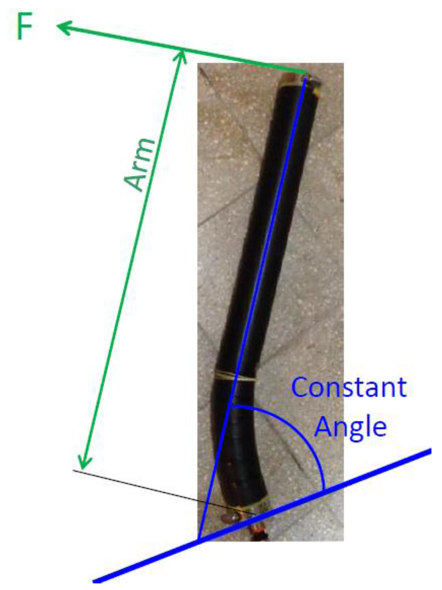
For more complete characterization of this prototype, a series of blocked moment experiments were conducted. In each experiment, the angle of the HELM was held constant using a cable with a force gage connected to the tip of the actuator. The cable was perpendicular to the last long section of the HELM. For each constant angle, the pressure was applied in steps and the force and arm where measured to yield the moment about the root of the HELM (see Figure 9). This process was repeated for a few angles.
Figure 9.
Blocked moment Experiment.

Figure 10 presents the measurements compared with theory.
Figure 10.
Blocked moment versus pressure, for prototype 3 of the HELM at different angles. Circles present experimental measurements, while lines present theoretical results.
Figure 10.
Blocked moment versus pressure, for prototype 3 of the HELM at different angles. Circles present experimental measurements, while lines present theoretical results.

6. Optimization of Use
This section considers a simple test case to study the effects of the design parameters on the efficiency. Suppose a HELM of length l with a single hinge at the base lifts a weight w located at its tip. The moment load by gravity about the hinge is M = −wl cos(B). Equation (11) can be numerically solved to yield the deflection angle for the supplied pressure, and by calculating the strains in the active membrane, the energy loss is interpolated from the approximation given in Figure 4. Yong’s modulus is taken as approx. E = 1.709 MPa for nitrile rubber; Other parameres of the HELM are α = 15°, τ = 2 mm and R = 30 mm.
Figure 11 presents the results of this test case. The efficiency was computed for two cases: when pressure is raised continously from 0 to 3 bar, and when it is raised from 1.5 to 3 bar. For nitrile rubber, in the former case, the best efficiency is at the highest load (10 N), and, in the latter, it occures at the lowest load (1 N) due to changes in mean elongation and elongation range. Little differences occur with natural rubber as the lines coincide. This demonstrates the importance of the selection of proper parameters to optimize a specific oparation of the HELM.
Figure 11.
(Left)—Response Angle of the HELM under different loading weights, W = 1, 2…10 N marked by red to violet lines, respectively. Solid lines are for natural rubber and dashed lines for nitrile rubber. (Center)—Bending moment at base, for each corresponding case. (Right)—actuation efficiency vs. weight load, for nitrile (dashed line) and natural (solid line) rubber. Red marks a pressure range of 1.5–3 Bar and blue 0–3 Bar.

The above efficiency assessment does not include losses in the pressure supply unit. We have aimed at computing energy losses in the HELM actuator itself, which stem from hysteresis. In principle, the energy supplied to the actuator (the integration of pressure by volume ∫PdV) may be recycled as the HELM releases pressure. The overall efficiency is the mechanical efficiency of the actuator multiplied by the hydraulic efficiency of the activation pressure device.
7. Conclusions and Future Work
HELM is a new type of hydraulic actuator that may be used for soft robotics and marine propulsion. Through the range of design parameters (head angle, radius, material, etc.), its motion characteristics can be controlled to yield various bending shapes at different sizes and input pressures.
The linear theoretical formulation of the HELM hinge was found to be reasonably applicable for small rotation angles. Nonlinear formulation, based on experimental material curves is found to be more suitable for larger deflections and nonlinear materials such as nitrile rubber. Further experimentation with different radii and head angles, exhibiting various strain ranges, is necessary. The next step would be dynamic analysis and experimentation, aiming at minimizing energy losses during cyclic bending and relaxation.
As previously stated, one of the key benefits of the HELM design is the ability to choose the strain range exhibited by the active material in order to minimize hysteresis, contributing to better actuation efficiency.
For example, based on the material characterization preformed, a HELM made of nitrile rubber with a required motion that corresponds to an elongation range of 40% would use a starting elongation of 160%. Similarly, at an elongation range of 80%, a starting elongation of 120% would be selected to minimize losses (see Figure 4).
Preferably, the HELM would have been made of natural rubber and integrated by a vulcanization process. The natural rubber presents small hysteresis (about 1%) and better elastic linearity, while vulcanization provides stronger connection of the hinges.
One possible application is an assembly of few HELMs to activate a fishlike fin at a desired kinematics to obtain thrust. Figure 12 illustrates three HELMs embedded into a silicone fin construction. This prototype has been fabricated and evaluated by towing tank experiments. Currently, we are developing a hydro-elastic mathematical model to predict the performance of the propulsion fin. The aim of this paper is to present the HELM, while a future publication will present the mathematical model and experiments on the propulsion fin.
Figure 12.
Prototype for underwater propulsion mechanism powered by three HELMs embedded in a silicon fin.
Figure 12.
Prototype for underwater propulsion mechanism powered by three HELMs embedded in a silicon fin.

Acknowledgments
This research was supported by the Technion Autonomous Systems Program (TASP) Land & Sea Research Centers.
Author Contributions
N. Drimer conceived the HELM concept and guided J. Mendelson (MSc. Thesis) and A. Peleg (System Engineer); J. Mendelson performed mathematical formulation and modeling, experiments, data processing and documentation; A. Peleg conducted the detailed design, fabrication and testing of the prototypes.
Conflicts of Interest
The authors declare no conflict of interest.
References
- Cai, Y.; Bi, S.; Zheng, L. Design and Experiments of a Robotic Fish Imitating Cow-Nosed Ray. J. Bionic Eng. 2010, 7, 120–126. [Google Scholar] [CrossRef]
- Chou, C.-P.; Hannaford, B. Static and Dynamic Characteristic of McKibben Pneumatic Artificial Muscles. Robot. Autom. 1994, 1, 281–286. [Google Scholar]
- Zhang, Z.; Philen, M. Pressurized artificial muscles. J. Intell. Mater. Syst. Struct. 2011, 23, 255–268. [Google Scholar] [CrossRef]
- Daerden, F.; Lefeber, D. Pneumatic artificial muscles: Actuators for robotics and automation. Eur. J. Mech. Environ. Eng. 2002, 47, 11–21. [Google Scholar]
- Zheng, H.; Shen, X. Double Acting Muscle Actuator for Bio-Robotic Systems. Actuators 2013, 2, 129–144. [Google Scholar] [CrossRef] [PubMed]
- Shapiro, Y.; Wolf, A.; Gabor, K. Bi-bellows: Pneumatic bending actuator. Sens. Actuators A Phys. 2011, 167, 484–494. [Google Scholar] [CrossRef]
- Suzumori, K.; Endo, S.; Kanda, T.; Kato, N.; Suzuki, H. A Bending Pneumatic Rubber Actuator. In Proceedings of the IEEE International Conference on Robotics & Automation, Roma, Italy, 10–14 April 2007.
- Yang, Q.; Zhang, L.; Bao, G.; Xu, S.; Ruan, J. Research on Novel Flexible Pneumatic Actuator FPA. In Proceedings of the 2004 IEEE Conference on Robotics, Automation and Mechatronics, Singapore, 1–3 December 2004.
- Tanaka, Y. Study of Artificial Rubber Muscle. Mechatronics 1993, 3, 59–75. [Google Scholar] [CrossRef]
- O’Brien, D.J.; Lane, D.M. 3D Force Control System Design for A Hydraulic Parallel Bellows Continuum Actuator. In Proceedings of the 2001 IEEE International Conference on Robotics & Automation, Seoul, Korea, 21–26 May 2001.
- Sfakoitakis, M.; Lane, D.M.; Davies, B.C. An experimental undulating-fin device using the Parallel Bellows Actuator. In Proceedings of the 2001 IEEE International Conference on Robotics & Automation, Seoul, Korea, 21–26 May 2001.
- Hirai, S.; Masui, T.; Kawamura, S. Prototyping Pneumatic Group Actuators Composed of Multiple Single-motion Elastic Tubes. In Proceedings of the 2001 IEEE International Conference on Robotics & Automation, Seoul, Korea, 21–26 May 2001.
© 2016 by the authors; licensee MDPI, Basel, Switzerland. This article is an open access article distributed under the terms and conditions of the Creative Commons by Attribution (CC-BY) license (http://creativecommons.org/licenses/by/4.0/).
Share and Cite
MDPI and ACS Style
Drimer, N.; Mendelson, J.; Peleg, A. A New Type of Hydraulic Muscle. Actuators 2016, 5, 3. https://doi.org/10.3390/act5010003
AMA Style
Drimer N, Mendelson J, Peleg A. A New Type of Hydraulic Muscle. Actuators. 2016; 5(1):3. https://doi.org/10.3390/act5010003
Chicago/Turabian StyleDrimer, Nitai, Jonathan Mendelson, and Amitai Peleg. 2016. "A New Type of Hydraulic Muscle" Actuators 5, no. 1: 3. https://doi.org/10.3390/act5010003
Note that from the first issue of 2016, this journal uses article numbers instead of page numbers. See further details here.